
John Deere Tractors 5215, 5315, 5415, 5515 High Crop Diagnosis & Tests Service Manual (TM4856)
Complete All Inclusive Technical Manual with Electrical Wiring Diagrams for John Deere Tractors 5215, 5315, 5415, 5515 and 5515 High Crop, with all the shop information to maintain, diagnose, repair, and rebuild like professional mechanics (Diagnosis, Operation, Tests, Repair, Service, Troubleshooting).
John Deere Tractors 5215, 5315, 5415, 5515 High Crop workshop technical service manual includes:
* Numbered table of contents easy to use so that you can find the information you need fast.
* Detailed sub-steps expand on repair procedure information
* Numbered instructions guide you through every repair procedure step by step.
* Troubleshooting and electrical service procedures are combined with detailed wiring diagrams for ease of use.
* Notes, cautions and warnings throughout each chapter pinpoint critical information.
* Bold figure number help you quickly match illustrations with instructions.
* Detailed illustrations, drawings and photos guide you through every procedure.
* Enlarged inset helps you identify and examine parts in detail.
tm4856 - 5215, 5315, 5415, 5515 and 5515 High Crop Tractors Technical Manual.pdf
tm4856 - 5215, 5315, 5415, 5515 and 5515 High Crop Tractors Technical Manual.epub
Total Pages: 3,014 pages
File Format: PDF/EPUB/MOBI/AZW (PC/Mac/Android/Kindle/iPhone/iPad; bookmarked, ToC, Searchable, Printable)
Language: English
MAIN SECTIONS
Foreword
Edition
Safety
Safety Measures
General Information
Specifications
Tune-Up
Predelivery Inspection
Engine - Repair
Removal and Installation of Engine Components
Fuel and Air Intake Systems - Repair
Speed Control Linkage
Fuel System
Air Intake System
Electrical System - Repair
Battery, Starting Motor and Alternator
Switches and Sensors
Transmission - Repair
Removal and Installation of Power Train Components
Clutch
Hi-Lo Clutch (24/24-Speed Transmission)
Transmission
24/12-Speed Transmission - Repair
Removal and Installation of 24/12-Speed Transmission Components
Clutch - 24/12-Speed Transmission
El.-Hydr. High/Low/Reverse Clutch (24/12-Speed Transmission)
Drive Systems - Repair
Component Removal and Installation
Front-Wheel Drive Clutch - Transmission
Differential
Final Drives
Power Take-Off
Transmission Housing Sensors
Steering and Brake Systems - Repair
Steering System
Brake System
Hydraulic System - Repair
Hydraulic Pump and Filter
Hitch
Three-Point Hitch
Selective Control Valves
Miscellaneous - Repair
Removal and Installation of Components
Front Axle
Front and Rear Wheels
Trailer Mounting and Swinging Drawbar
Fenders
Operator's Cab and Open Operator's Station - Repair
Removing and Installing Operator's Cab/Open Operator's Station
Controls and Instruments
Air Conditioning System
Heating System
Operator's Cab
Open Operator's Station
Operator's Seat
Diagnostic Trouble Codes
Electro-Hydraulic Management
Electronic Hitch Sensing
Observable Symptoms
Fuel and Air Intake System
Electrical System
Power Train
PowrReverser Transmission
Steering and Brakes
Front-Wheel Drive
Engine - Operation and Tests
Operational Check-Out
Tests and Adjustments
Fuel, Air Intake and Cooling Systems
Tests and Adjustments
Theory of Operation
Electrical System - Operation and Tests
SE01 - Motor Starting and Charging System
SE02 - Instrument Panel
SE03 - Horn
SE06 - Lighting System
SE07 - Work Lights
SE09 - Radio, Dome and Console Light
SE10 - Fan and Air-Conditioning System
SE11 - Wiper and Washer System
SE13 - Beacon Light
SE14 - Power Outlet
SE15A - Electronic Hitch Sensing (EHS)
SE15B - Electronic Hitch Sensing (EHS II)
SE16A - Hazard Warning and Turn Signal Lights
SE16B - PTO System
SE16C - Front-Wheel Drive, Differential Lock and Braking System
SE21 - Flow Divider Valve
SE26A - Electro-Hydraulic Management (EHM)
SE26B - Electro-Hydraulic Management (EHM II)
SE27 - Electro-Hydraulic Hi-Lo
Component Information - Connectors
Component Information - Wiring Harnesses
Component Information - Electrical Parts
Component Information - Ground Connection
Wiring Diagrams
Electronic Control Units
Operation and General Information on Diagnostics
Electro-Hydraulic Management
EHS - Electronic Hitch Sensing
Power Train - Operation and Tests
Component Location
Theory of Operation
Diagnosis, Tests and Adjustments
24/12-Speed Transmission - Operation and Tests
Component Location
Theory of Operation
Diagnosis, Tests and Adjustments
Steering and Brake Systems - Operation and Tests
Component Location
Theory of Operation
Diagnosis, Tests and Adjustments
Hydraulic System - Operation and Tests
Component Location
Theory of Operation
Diagnosis
Tests
Adjustments
Hydraulic System Schematics
Miscellaneous
Operational Checks
Air-Conditioning System - Operation and Tests
Component Location
Theory of Operation
Diagnosis, Tests and Adjustments
Special Tools
Special Tools (Dealer-Fabricated)
Special Tools and Test Equipment
TABLE OF CONTENTS............1
Section 05: Safety............1288
Group 05: Safety Measures............49
Recognize Safety Information............51
Understand Signal Words............52
Section 10: General Information............2937
Group 05: Specifications............2884
Summary of References — Specifications............2884
Engine............90
Transmission............92
Front-Wheel Drive Clutch............93
Hydraulic System............94
Electrical System............95
Capacities............96
Sound Level............98
Fuel System............99
Brakes............100
Three-Point Hitch............101
Loads and Weights............102
Towable Loads............103
Shipping Weights............104
Maximum Permissible Axle Loads and Total Weights............105
Load Capacity Of Tires............107
Load Capacity of Tires With Front Loader............111
Observe Rear Wheel Tread Width Limitations............112
Metric Bolt and Screw Torque Values............113
Unified Inch Bolt and Screw Torque Values............115
Diesel Fuel............117
Handling and Storing Diesel Fuel............118
Do Not Use Galvanized Containers............119
Fill Fuel Tank............120
Diesel Engine Break-In Oil............122
Diesel Engine Oil............123
Transmission and Hydraulic Oil............125
Front-Wheel Drive Axle and Rear Drop Axle Oil............126
Grease............127
Oil Filters............128
Lubricant Storage............129
Mixing of Lubricants............130
Diesel Engine Coolant............131
Operating in Warm Temperature Climates............132
Alternative and Synthetic Lubricants............133
Serial Number Plates............134
Product Identification Number Location............135
Engine Serial Number............136
Fuel Injection Pump Serial Number Location............137
Alternator Serial Number Location............138
Power Steering Valve Serial Number Location............139
Air Conditioning Compressor Serial Number Location............140
Transmission Serial Number Location............141
Front Axle (2WD) Serial Number Location............142
Front-Wheel Drive Serial Number............143
Group 10: Tune-Up............84
Summary of References - Tune-Up............145
Using High-Pressure Washers............146
Preliminary engine test............147
Clean Radiator and Oil Cooler............148
Cleaning Air Conditioning System Condenser (If Equipped)............149
Check Hoses and Hose Clamps............150
Clean Engine Crankcase Vent Tube............151
Cleaning the Dust Unloading Valve............152
Engine Air Filter............153
Cleaning the Primary Filter Element............155
Cleaning a Dusty Element............156
Secondary (Safety) Element............157
Cleaning Cab Air Filters............158
Check Belt Wear and Tension............160
Check Engine Oil Level............162
Check Coolant Level............163
Check Transmission/Hydraulic System Oil Level............165
Checking the Fuel Filter............166
Bleeding Fuel System............237
Adjust Hand Throttle............169
Starting Motor............170
Battery - Checking Specific Gravity............171
Check Neutral Start System............172
Check Setting of Head Lights and Work Lights............174
Check Lights............175
Final Engine Check............176
Tractor Operation Check............177
Group 15: Predelivery Inspection............179
Predelivery Inspection............179
Section 20: Engine — Repair............180
Group 00: Removal and Installation of Engine Components............180
Summary of References — Remove and Install Engine Components............182
Engine Repair............183
Essential Tools............2703
Specifications............2884
Remove Engine............186
Install Engine............188
Water Pump Repair............191
Remove and Inspect Radiator............192
Install Radiator............197
Remove and Install Oil Cooler............201
Replace Thermostat............203
Section 30: Fuel and Air Intake Systems — Repair............205
Group 05: Speed Control Linkage............205
Summary of References — Speed Control Linkage............207
Remove and Install Speed Control Linkage for Tractors up to Serial. No. 208300............208
Inspect and Repair Speed Control Linkage for Tractors up to Serial. No. 208300............211
Adjust Engine Idle Speed for Tractors up to Serial. No. 208300............213
Adjust Throttle Lever for Tractors up to Serial. No. 208300............214
Adjust Hand Throttle Lever and Accelerator Pedal for Tractors from Serial. No. 208301............215
Recondition Hand Throttle Lever and Accelerator Pedal for Tractors from Serial. No. 208301............217
Group 10: Fuel System............99
Summary of References — Fuel System............220
Injection Pump, Nozzle and Governor Repair............221
Remove, Inspect and Install Fuel Tank............222
Replace Fuel Filter............229
Replace Primary Fuel Filter............230
Remove and Install Fuel Filter............231
Replace Fuel Transfer Pump............232
Replace Adapter in Fuel Line............235
Bleeding Fuel System............237
Group 15: Air Intake System............205
Summary of References — Air Intake System............240
Turbocharger Repair............241
Remove and Install the Air Filter Element............242
Remove and Install Air Intake Hoses............244
Replace Air Filter Restriction Switch............245
Section 40: Electrical System — Repair............246
Group 05: Battery, Starting Motor and Alternator............246
Summary of References — Battery, Starting Motor and Alternator............248
Starting Motor Repair............249
Remove and Install Battery............250
Remove and Install Starting Motor............253
Alternator/Regulator Repair............257
Replace Alternator/Regulator............258
Checking Belt Wear and Tension............261
Group 10: Switches and Sensors............246
Summary of References — Switches and Sensors............264
Replace Air Filter Restriction Switch B02............265
Replace Fuel Level Sensor B03............266
Replace Engine Oil Pressure Switch B04............268
Replace Parking Brake Switch B05............269
Replace Ground Speed Sensor B06............270
Replace PTO Speed Selection Switch B07............271
Replace Neutral Start Switch B36............272
Replace Coolant Temperature Sensor B56............274
Replace Clutch Pedal Potentiometer B65............275
Replace Engine Speed Sensor B72............276
Replace Brake Pedal Switches B112............277
Replace Main Switch S01............278
Replace Turn Signal Light Switch S08............280
Replace Light and Horn Switch S09............282
Replace PTO Mode Switch S21............284
Replace Clutch Pedal Switch S72............285
Replace Hazard Warning Light Switch S106............287
Replace Fuel Shut-Off Solenoid Valve Y13............289
Replace Instrument Panel............290
Section 50: Transmission — Repair............293
Group 00: Removal and Installation of Power Train Components............293
Summary of References — Remove and Install Power Train Components............296
Specifications............2884
Separate Engine from Clutch Housing............298
Install Engine to Clutch Housing............311
Separate Clutch Housing from Transmission - Not for 24/12 Speed Transmission............325
Install Clutch Housing to Transmission - Not for 24/12 Speed Transmission............333
Replace Clutch Housing Seal - 12/12 Speed Transmission............341
Replace Clutch Housing Seal - 24/24 Speed Transmission............342
Remove and Install Rear PTO Drive Shaft............348
Group 05: Clutch............293
Summary of References — Clutch............351
Specifications............2884
Inspect and Repair Clutch Pedal and Linkage - Not for 24/12 Speed Transmission............353
Remove and Install Clutch Assembly - Not for 24/12 Speed Transmission............355
Disassemble and Inspect Clutch Assembly - Not for 24/12 Speed Transmission............358
Assemble Clutch Assembly - Not for 24/12 Speed Transmission............367
Traction Clutch Finger Adjustment - Not for 24/12 Speed Transmission............374
PTO Clutch Finger Adjustment - Not for 24/12 Speed Transmission............376
Remove and Inspect Clutch Release Mechanism - Not for 24/12 Speed Transmission............378
Install Clutch Release Mechanism - Not for 24/12 Speed Transmission............381
Group 10: Hi-Lo Clutch (24/24-Speed Transmission)............293
Summary of References - Hi-Lo Clutch (24/24-Speed Transmission)............384
Specifications............2884
Remove and Inspect Mechanical Hi-Lo Drive............386
Install Mechanical Hi-Lo Drive............391
Disassemble, Inspect and Assemble Mechanical Hi-Lo Shift Shaft Assembly............395
Disassemble, Inspect and Assemble Mechanical Hi-Lo Synchronizer............396
Disassemble, Inspect and Assemble Mechanical Hi-Lo Drive Shaft............398
Disassemble, Inspect and Assemble Mechanical Hi-Lo Reduction Shaft............400
Inspect and Repair Mechanical Hi-Lo Shift Lever............402
Seal Ring Replacement of Hydraulic Hi-Lo Clutch Drive Shaft............404
Remove and Inspect Hydraulic Hi-Lo Clutch Assembly............412
Install Hydraulic Hi-Lo Clutch Assembly............418
Disassemble, Inspect and Assemble Hydraulic Hi-Lo Clutch............425
Disassemble, Inspect and Assemble Hydraulic Hi-Lo Drive Shaft............428
Group 20: Transmission............92
Summary of References — Transmission............431
Specifications............2884
Remove and Install Transmission............433
Inspect and Repair Gear and Range Shift Levers............435
Remove, Inspect and Install Range Shaft............439
Range Shaft End Play Adjustment............443
Remove, Inspect and Install Primary and Reverse Shafts............445
Primary Shaft End Play Adjustment............452
Remove, Inspect and Install Pinion Shaft............454
Pinion Shaft Cone Point Adjustment............457
Pinion Bearing Preload Adjustment............460
Remove, Inspect and Install Secondary Shaft............461
Secondary Shaft End Play Adjustment............466
Section 51: 24/12-Speed Transmission — Repair............468
Group 00: Removal and Installation of 24/12-Speed Transmission Components............468
Summary of References — Remove and Install 24/12-Speed Transmission Components............470
Separate Clutch Housing from Transmission - Only for 24/12-Speed Transmission............471
Install Clutch Housing to Transmission - Only for 24/12-Speed Transmission............477
Replace Clutch Inner Control Seal - Only for 24/12-Speed Transmission............483
Remove and Install Air Pump............490
Remove and Install Lube Oil Valve............493
Group 05: Clutch - 24/12-Speed Transmission............92
Summary of References - 24/12-Speed Transmission Clutch............495
Specifications............2884
Remove and Install Clutch Assembly - Only for 24/12-Speed Transmission............497
Disassemble and Inspect Clutch Assembly - Only for 24/12-Speed Transmission............499
Assemble Clutch Assembly - Only for 24/12-Speed Transmission............503
PTO Clutch Finger Adjustment - Only for 24/12-Speed Transmission............505
Remove and Inspect Clutch Release Mechanism - Only for 24/12-Speed Transmission............507
Install Clutch Release Mechanism - Only for 24/12-Speed Transmission............509
Group 15: El.-Hydr. High/Low/Reverse Clutch (24/12-Speed Transmission)............468
Summary of References - Electro-Hydraulic High/Low/Reverse Clutch (24/12-Speed Transmission)............513
Remove Electro-Hydraulic High/Low/Reverse Clutch Assembly (24/12-Speed Transmission)............514
Install Electro-Hydraulic High/Low/Reverse Clutch Assembly (24/12-Speed Transmission)............516
Replace Clutch Housing Seal - Only for 24/12-Speed Transmission............518
Replace Seal Rings of Low/Reverse Clutch Drive Shaft............523
Disassemble, Inspect and Assemble Electro-Hydraulic High Clutch (24/12-Speed Transmission)............528
Disassemble, Inspect and Assemble Electro-Hydraulic Low Clutch (24/12-Speed Transmission)............534
Disassemble, Inspect and Assemble Electro-Hydraulic Reverse Clutch (24/12-Speed Transmission)............540
Section 56: Drive Systems — Repair............546
Group 00: Component Removal and Installation............546
Summary of References — Remove and Install Components............549
Specifications............2884
Remove and Install Front-Wheel Drive Clutch............551
Remove and Install Differential Assembly............553
Remove and Install Final Drive Assembly............556
Group 15: Front-Wheel Drive Clutch — Transmission............92
Summary of References — Front-Wheel Drive Clutch............561
Service Equipment and Tools............868
Specifications............2884
Disassemble and Inspect Front-Wheel Drive Clutch — Hydraulic Operated............564
Front-Wheel Drive Clutch Cross Section — Hydraulic Operated............566
Assemble Front-Wheel Drive Clutch — Hydraulic Operated............568
Disassemble and Inspect Front-Wheel Drive Clutch — Hydraulic Operated with Park Brake............571
Front-Wheel Drive Clutch Cross Section – Hydraulic Operated with Park Brake............574
Assemble Front-Wheel Drive Clutch – Hydraulic Operated with Park Brake............576
Disassemble and Inspect Front-Wheel Drive Clutch — Mechanically Operated............582
Front-Wheel Drive Clutch Cross Section — Mechanically Operated............585
Assemble Front-Wheel Drive Clutch — Mechanically Operated............587
Group 20: Differential............546
Summary of References — Differential............596
Essential Tools............2703
Service Equipment and Tools............868
Specifications............2884
Disassemble, Inspect and Assemble Two Pinion Differential Assembly............600
Two Pinion Differential Bearing Preload Adjustment............602
Two Pinion Differential Backlash Adjustment............604
Disassemble, Inspect and Assemble Four-Pinion Differential Assembly............607
Four Pinion Differential Backlash Adjustment............609
Four Pinion Differential Bearing Preload Adjustment............611
Inspect and Repair Differential Lock Pedal and Linkage............612
Inspect and Repair Hydraulic Differential Lock and Linkage............614
Remove, Inspect and Install Differential Lock Assembly............616
Group 25: Final Drives............547
Summary of References — Final Drives............621
Specifications............2884
Remove and Inspect Planetary Drive Assembly (3-Cylinder Tractors)............623
Remove and Inspect Planetary Drive Assembly (4-Cylinder Tractors)............625
Install Planetary Drive Assembly (3-Cylinder Tractors)............627
Install Planetary Drive Assembly (4-Cylinder Tractors)............631
Remove, Inspect and Install Axle Shaft Assembly (3-Cylinder Tractors)............633
Remove, Inspect and Install Axle Shaft Assembly (4-Cylinder Tractors)............636
Disassemble, Inspect and Assemble Gears and Shafts of Final Drive (HighCrop Version)............639
Group 30: Power Take-Off............547
Summary of References — Power Take-Off............643
Service Equipment and Tools............868
Inspect and Repair Rear PTO Clutch Lever and Linkage............645
Inspect and Repair Rear PTO Engagement Lever and Linkage............649
Disassemble, Inspect and Assemble PTO Shift Leverage Assembly............651
Disassemble, Inspect and Assemble Rear PTO Engagement Control............653
Disassemble, Inspect and Assemble Rear PTO Engagement Sleeve............655
Disassemble, Inspect and Assemble Rear PTO Drive Shaft Assembly............658
Group 35: Transmission Housing Sensors............547
Disassemble, Inspect and Assemble Transmission Housing Sensors............666
Section 60: Steering and Brake Systems — Repair............671
Group 05: Steering System............671
Summary of References — Steering System............674
Specifications............2884
Remove and Install Steering Column and Valve............676
Disassemble and Inspect Steering Valve............678
Assemble Steering Valve............682
Remove and Install Steering Cylinder............687
Remove and Install Steering Cylinder (HighCrop Tractor)............689
Disassemble, Inspect and Assemble Steering Cylinder............691
Disassemble, Inspect and Assemble Steering Cylinder (HighCrop Tractor)............693
Remove, Inspect and Install Tie Rod Assembly............695
Remove, Inspect and Install Tie Rod Assembly (HighCrop Tractor)............697
Inspect and Replace Steering Hydraulic Lines............699
Group 10: Brake System............671
Summary of References — Brake System............703
Specifications............2884
Change Brake System Oil............705
Remove and Install Brake Valve and Pedals............707
Disassemble and Inspect Brake Pedals............709
Disassemble Brake Valve............710
Brake Valve Cross Section............712
Assemble Brake Valve............714
Remove and Inspect Brakes............717
Install Brakes............719
Remove and Install Trailer Brake Valve............721
Disassemble and Inspect Trailer Brake Valve............722
Inspect and Replace Brake Hydraulic Lines............726
Remove, Inspect and Install Hydraulic Actuator............728
Remove, Inspect and Install Brake Linkage............730
Remove, Inspect and Install Parking Brake Lever............732
Remove, Inspect and Install Parking Brake Linkage............734
Remove, Inspect and Install Parking Brake Lever and Linkage on Electro-Hydraulic MFWD............738
Trailer Brake Valve System Components............740
Remove and Inspect Trailer Brake Valve............742
Install Trailer Brake Valve and Lines............745
Section 70: Hydraulic System — Repair............748
Group 05: Hydraulic Pump and Filter............748
Summary of References — Hydraulic Pump and Filter............751
Specifications............2884
Remove and Install Hydraulic Pump............753
Remove Hydraulic Pump External Components............755
Disassemble and Inspect Hydraulic Pump............757
Assemble Hydraulic Pump............760
Install Hydraulic Pump External Components............762
Remove and Install Hydraulic Filter/Manifold............764
Inspect and Replace Hydraulic Suction Lines............765
Inspect and Replace Hydraulic Supply Lines............766
Group 10: Hitch............748
Summary of References — Rockshaft............771
Essential Tools............2703
Specifications............2884
Inspect and Repair Rockshaft Control Lever and Linkage............774
Remove, Inspect and Install Rockshaft Control Valve............777
Remove, Inspect and Install EHS............781
Remove, Inspect and Install EHS II............786
Remove, Inspect and Install Sensing Linkage............790
Sensing Spring Adjustment............793
Safety and Relief Valve Adjustment............794
Remove and Install Rockshaft Case............796
Remove, Inspect and Install Rockshaft Lift Arms and Cylinder............798
Remove Rockshaft Control Linkage............801
Inspect and Repair Rockshaft Control Linkage............804
Install Rockshaft Control Linkage............808
Rockshaft Sensitivity Adjustment............2897
Rockshaft Position Control Lever Adjustment............813
Rockshaft Draft Control Lever Adjustment............814
Distributor Control Valve Adjustment............816
Group 15: Three-Point Hitch............101
Summary of References — Three-Point Hitch............819
Inspect and Repair Draft Links............820
Inspect and Repair Adjustable Lift Link............822
Inspect and Repair Center Link............824
Group 20: Selective Control Valves............749
Summary of References — Selective Control Valves............827
Selective Control Valve and Lever Assembly............828
Remove and Install Selective Control Valves (SCV)............832
Disassemble, Inspect and Assemble Selective Control Valve............834
Disassemble, Inspect and Assemble Selective Control Valve Levers............840
Selective Control Valve Levers — Exploded View............843
Remove and Install Flow Divider Valve............845
Section 80: Miscellaneous — Repair............848
Group 00: Removal and Installation of Components............848
Summary of References — Removal and Installation of Components (Miscellaneous)............851
Specifications............2884
Remove Hood and Side Panels............853
Install Hood and Side Panels............855
Remove and Install Front Axle............857
Remove and Install Front Axle (HighCrop Tractor)............859
Remove, Inspect and Install Front Axle Drive Shaft............861
Remove and Install Front Axle Drive Assembly............864
Group 10: Front Axle............848
Summary of References — Front Axle............867
Service Equipment and Tools............868
Specifications............2884
Inspect and Replace Pivot Pin and Bushings............870
Remove and Install Spindle Assembly............871
Remove and Install Spindle Assembly (HighCrop Tractor)............873
Inspect and Replace Spindle Shaft Bushings............875
Inspect and Replace Front Wheel Bearings............877
Inspect and Replace Front Wheel Bearings (HighCrop Tractor)............879
Group 15: Front and Rear Wheels............848
Remove and Install Front or Rear Wheels............884
Group 20: Trailer Mounting and Swinging Drawbar............898
Summary of References - Trailer Mounting and Swinging Drawbar............898
Checking the Manually-Operated Hitch (EEC Type) for Wear............889
Checking the Manually-Operated Hitch (CUNA Type) for Wear (Italy, Spain and Portugal Only)............891
Checking the Tow-Hook for Wear............893
Checking the Swinging Drawbar for Wear............894
Guide Rails for Height-Adjustable Trailer Hitch............896
Swinging Drawbar............898
Group 25: Fenders............848
Summary of References — Fenders............901
Remove and Install Fenders (Open Operator's Station Tractors)............902
Remove and Install Fenders (Cab Tractors)............904
Section 90: Operator's Cab and Open Operator's Station — Repair............908
Group 00: Removing and Installing Operator's Cab/Open Operator's Station............908
Summary of References — Removing and Installing Operator's Cab/Open Operator's Station............912
Remove Operator's Cab............913
Install Operator's Cab............933
Remove Open Operator's Station............951
Install Open Operator's Station............965
Group 05: Controls and Instruments............908
Summary of References — Controls and Instruments............981
Remove Control Lever Moldings............982
Install Control Lever Moldings............985
Remove Instrument Panel............988
Install Instrument Panel............991
Remove and Install EHS Control Panel............992
Remove and Install EHS II Control Panel............994
Remove and Install EHM Control Unit............996
Remove and Install EHM II Control Unit............997
Group 15: Air Conditioning System............908
Summary of References — Air-Conditioning System............999
Essential Tools............2703
Specifications............2884
Torques for Tightening Refrigerant Hoses............1005
Safety At Work............1006
Handling Refrigerant............1007
In An Emergency............1008
Safety Equipment............2956
Storage of Refrigerant Containers............2958
R134a Refrigerant............2959
Important............1012
Discharging the System............1013
Evacuating the System............1015
Filling With Refrigerant Oil............1017
Filling the System............1019
Topping Up a Partly Discharged System............1022
Leakage Test............1024
Replace Air-Conditioning Receiver-Drier............2952
Remove, Inspect and Install Air-Conditioning Condenser............2951
Remove, Inspect and Install Air-Conditioning Compressor (3-Cylinder Version)............1029
Remove, Inspect and Install Air-Conditioning Compressor (4-Cylinder Version)............1033
Checking Level in the Compressor............2950
Air-Conditioning Evaporator — Parts............1037
Remove and Install Air-Conditioning Evaporator............1039
Group 20: Heating System............909
Summary of References — Heating System............1050
Remove, Inspect and Install Heater Components............1051
Remove, Inspect and Install Blower Motor............1059
Group 25: Operator's Cab............909
Summary of References — Operator's Cab............1063
Specifications............2884
Remove and Install Sun Visor............1065
Remove and Install Front Windshield............1066
Front Windshield, Exploded View............1070
Remove and Install Lower Front Windows............1072
Lower Front Windows, Exploded View............1074
Remove and Install Cab Door............1075
Remove and Install Inner Handle............1077
Cab Door, Exploded View............1079
Remove and Install Rear Side Cab Windows............1081
Rear Side Cab Windows, Exploded View............1083
Remove and Install Rear Window............1084
Rear Window, Exploded View............1087
Remove and Install Cab Recirculating/Fresh Air Filter............1089
Group 30: Open Operator's Station............909
Summary of References — Open Operator's Station............1092
Remove and Install 4-post ROPS............1093
Remove and Install 2-post ROPS............1096
Group 35: Operator's Seat............910
Remove and Install Operator's Seat and Support............1101
Section 211: Diagnostic Trouble Codes............1103
Group EHM: Electro-Hydraulic Management............1103
EHM Diagnostic Trouble Codes - Summary of References............1107
Error and Calibration Codes............1109
EHM 00 - Control Unit Internal Fault (EHM or EHM II)............1103
EHM 12 - Transmission Oil Temperature Sensor, Signal Too High (EHM or EHM II)............1103
EHM 13 - Transmission Oil Temperature Sensor, Signal Too Low (EHM II)............1103
EHM 15 - Clutch Pedal Potentiometer, Signal Voltage Too Low (EHM or EHM II)............1103
EHM 16 - Clutch Pedal Potentiometer, Signal Voltage Too High (EHM or EHM II)............1103
EHM 17 - Clutch Pedal Potentiometer Signal And Clutch Pedal Switch Status Do Not Match (EHM or EHM II)............1103
EHM 18 - Forward High Clutch Solenoid Valve, Shorted Or Open Circuit (EHM or EHM II)............1103
EHM 19 - Forward Low Clutch Solenoid Valve, Shorted Or Open Circuit (EHM or EHM II)............1103
EHM 20 - Reverse Clutch Solenoid Valve, Shorted Or Open Circuit (EHM or EHM II)............1103
EHM 21 - Clutch Valve Solenoids (Common Code For All Clutches) (EHM or EHM II)............1103
EHM 22 - Forward High Clutch Solenoid Valve, Supply Pin Shorted To 12 Volts (EHM or EHM II)............1103
EHM 23 - Forward Low Clutch Solenoid Valve, Supply Pin Shorted To 12 Volts (EHM or EHM II)............1103
EHM 24 - Reverse Clutch Solenoid Valve, Supply Pin Shorted To 12 Volts (EHM or EHM II)............1103
EHM 25 - Reverse Drive Lever Malfunction, Forward And Reverse Signals Received Simultaneously (EHM or EHM II)............1103
EHM 26 - Reverse Drive Lever Malfunction, Forward And Neutral Signals Received Simultaneously (EHM or EHM II)............1103
EHM 27 - Reverse Drive Lever Malfunction, Reverse And Neutral Signals Received Simultaneously (EHM or EHM II)............1103
EHM 28 - EHM Supply Critical - Voltage Low (EHM or EHM II)............1103
EHM 29 - EHM Supply Critical - Voltage High (EHM II)............1103
EHM 30 - Forward High or Reverse Clutch Valve Solenoid, Shorted to Ground (EHM II)............1103
EHM 35 - EHM 5-Volt Sensor Supply Critical - Voltage High (EHM II)............1103
EHM 36 - EHM 5-Volt Sensor Supply Critical - Voltage Low (EHM II)............1103
EHM 49 - Reverse Drive Lever Malfunction, Forward, Neutral and Reverse Signals Received Simultaneously (EHM II)............1103
EHM dLEr - Differential Lock Disengagement Solenoid Overcurrent (EHM II)............1103
EHM FdEr - Four-Wheel Drive Disengagement Solenoid Shorted to Ground (EHM II)............1103
EHM MrOE - Shut-Off Solenoid Valve of Shut-Off System Open (EHM II)............1103
EHM MrrF - Shut-Off Solenoid Valve Supply Pin Shorted to 12 Volts (EHM II)............1103
EHM MrSF - Shut-Off Solenoid Valve Supply Pin Shorted to Ground (EHM II)............1104
EHM OIL - Transmission Oil Temperature Too High (EHM II)............1104
EHM OILH - Transmission Oil Temperature Reached Maximum Limit (EHM II)............1104
EHM OILL - Transmission Oil Temperature Reached Minimum Limit (EHM II)............1104
EHM CFSE - Oil Filter Restriction Sensor Malfunction (EHM II)............1104
EHM FHSE - Forward High Clutch Pressure Sensor Malfunction (EHM II)............1104
EHM FLSE - Forward Low Clutch Pressure Sensor Malfunction (EHM II)............1104
EHM MrCE - Shut-Off Solenoid Valve Malfunction (EHM II)............1104
EHM MrSE - Shut-Off Solenoid Valve Malfunction (EHM II)............1104
EHM rESE - Reverse Clutch Pressure Sensor Malfunction (EHM II)............1104
EHM StOP - System Initial Check (EHM II)............1104
EHM DAtA - Calibration Parameters Out Of Range (EHM II)............1104
EHM CFCL - Oil Filter Restriction Sensor Malfunction EHM II............1104
EHM FHCE - Forward High Clutch Solenoid Valve Malfunction (EHM II)............1104
EHM FHOE - Forward High Clutch Solenoid Valve Malfunction EHM II............1104
EHM FLCE - Forward Low Clutch Solenoid Valve Malfunction (EHM II)............1104
EHM FLOE - Forward Low Clutch Solenoid Valve Malfunction EHM II............1104
EHM rECE - Reverse Clutch Solenoid Valve Malfunction (EHM II)............1104
EHM rEOE - Reverse Clutch Solenoid Valve Malfunction EHM II............1104
EHM PEd - Clutch Slipping For Excessive Time (EHM II)............1104
EHM nEU - Message............1104
Group EHS: Electronic Hitch Sensing............1104
Diagnosis (EHS)............1197
EHS01 - Position Sensor Failure............1104
EHS02 - Draft Sensor Failure............1104
EHS04 - EPROM Reading Failure............1104
EHS08 - Power Supply Less Than 10 Volts............1104
EHS16 - Power Supply Greater Than 16 Volts............1104
EHS32 - Lowering Solenoid Valve Failure............1104
EHS64 - Raising Solenoid Valve Failure............1104
Section 212: Observable Symptoms............1205
Group 30: Fuel and Air Intake System............1205
Problem with the Fuel Gauge............1205
Problem with Decreased Engine Performance............1205
Group 40: Electrical System............95
Problem with the Battery............1205
Problem with the Horn............1205
Problem with the Turn Signal Lights............1205
Problem with the Hazard Warning Lights............1205
Problem with the Headlights............1205
Problem with the Clearance Lights, Tail Lights, License Plate Light and Instrument Panel Light............1205
Problem with the Beacon Light............1205
Problem with the Rear Work Light............1205
Problem with Different Malfunctions that Appear Occasionally............1205
Problem with the EHS System............1205
Group 50: Power Train............1205
Problem with the Traction Clutch (Not for 24/12-Speed Transmission)............1205
Traction Clutch - Causes of Trouble............1228
Group 51: PowrReverser Transmission............92
Tractor does not move............1205
Problem with the Alert Lamp............1205
Problem with the Traction Clutch (Only for 24/12-Speed Transmission)............1205
Engine stalls with Forward-Low or Reverse engaged (Only for 24/12-Speed Transmission)............1205
Group 60: Steering and Brakes............100
Problem with the Brakes............100
Problem with the Steering............1205
Problem with the Trailer Brake............1205
Group 80: Front-Wheel Drive............1205
Problem with Noises when Driving with Front-Wheel Drive Engaged............1205
Problem with Unusual Vibration when Driving with Front-Wheel Drive Engaged............1205
Section 220: Engine — Operation and Tests............1276
Group 10: Operational Check-Out............1276
Operational Check-Out (Summary of References)............1278
Safety............1288
Preliminary Engine Tests............1280
Group 15: Tests and Adjustments............1276
Tests and Adjustments (Summary of References)............1282
Dynamometer Test............1283
Section 230: Fuel, Air Intake and Cooling Systems............1284
Group 15: Tests and Adjustments............1284
General Information............2937
Explanation of Checks............1287
Safety............1288
Special Tools............2962
Specifications............2884
Testing Air Intake System............1291
Testing the Low-Pressure Switch in Air Intake System............1292
Checking the Cooling System for Leaks............1293
Testing the Temperature at which the Thermostat opens............1295
Checking the Viscous Clutch of the Fan............1297
Checking the Fuel Transfer Pump............1298
Hand Throttle Lever and Accelerator Pedal Adjustment............1300
Group 20: Theory of Operation............1284
Fuel System - Description............1303
Fuel Filter/Priming Pump Operation............1305
Air Intake System - Theory of Operation............1307
Engine Cooling System Operation—3-Cylinder............1309
Engine Cooling System Operation—4-Cylinder............1311
Cooling System Radiator — Description............1313
Viscous Clutch of Fan — Theory of Operation............1314
Automatic Drive Belt Tensioner — Theory of Operation............1316
Cold Weather Starting Aid — Theory of Operation............1317
Section 240: Electrical System — Operation and Tests............1319
Group S01: SE01 - Motor Starting and Charging System............1319
SE01 - Motor Starting and Charging System (Summary of References)............1337
SE01A - Power Supply, Diagnostic Schematic and Circuit Test............1338
SE01A - Power Supply (Cab Harness), Diagnostic Schematic and Circuit Test............1344
SE01B - Starting System without EHM, Diagnostic Schematic and Circuit Test............1347
SE01C - Starting System with EHM or EHM II, Diagnostic Schematic and Circuit Test............1357
SE01D - Charging System, Diagnostic Schematic and Circuit Test............1371
SE01E - Intake Air Heater 3-Cyl. Tractors, Diagnostic Schematic and Circuit Test............1376
SE01E - Intake Air Heater 4-Cyl. Tractors, Diagnostic Schematic and Circuit Test............1380
Group S02: SE02 - Instrument Panel............1319
SE02 - Instrument Panel (Summary of References)............1386
SE02 - Power Supply to Instrument Panel, Diagnostic Schematic and Circuit Test............1387
SE02A - Fuel Gauge, Temperature Gauge, Rev Counter, Diagnostic Schematic and Circuit Test............1390
SE02B - Air Filter Restriction Indicator, Diagnostic Schematic and Circuit Test............1397
SE02C - Engine Oil Pressure Indicator, Diagnostic Schematic and Circuit Test............1400
SE02E - Transmission Speed Sensor B06, Diagnostic Schematic and Circuit Test............1403
SE02F - Engine Speed Sensor B72, Diagnostic Schematic and Circuit Test............1407
SE02G - Calibration Switch of Digital Instrument S51 (EHM or EHM II), Diagnostic Schematic and Circuit Test............1411
Group S03: SE03 - Horn............1319
SE03 - Horn (Summary of References)............1414
SE03 - Horn, Diagnostic Schematic and Circuit Test............1415
Group S06: SE06 - Lighting System............1319
SE06 - Lighting System (Summary of References)............1419
SE06A - Left Clearance Light, Right Tail Light and License Plate Light, Diagnostic Schematic and Circuit Test............1420
SE06A - Right Clearance Light, Left Tail Light and Instrument Panel Light, Diagnostic Schematic and Circuit Test............1425
SE06B - Headlights, Diagnostic Schematic and Circuit Test............1430
Group S07: SE07 - Work Lights............1319
SE07 - Work Lights (Summary of References)............1438
SE07A - Rear Work Light with Switch S61, Diagnostic Schematic and Circuit Test............1439
SE07B - Front Work Lights E18 (Cab Only), Diagnostic Schematic and Circuit Test............1442
SE07B - Rear Work Lights E11 (Cab Only), Diagnostic Schematic and Circuit Test............1454
Group S09: SE09 - Radio, Dome and Console Light............1320
SE09 - Radio, Dome and Console Light (Summary of References)............1462
SE09A - Radio A60, Diagnostic Schematic and Circuit Test............1463
SE09B - Dome Light E12, Diagnostic Schematic and Circuit Test............1469
Group S10: SE10 - Fan and Air-Conditioning System............1320
SE10 - Fan and Air-Conditioning System (Summary of References)............1473
SE10A - Fan Motor M07, Diagnostic Schematic and Circuit Test............1474
SE10B - Air-Conditioning System, Diagnostic Schematic and Circuit Test............1481
Group S11: SE11 - Wiper and Washer System............1320
SE11 - Wiper and Washer System (Summary of References)............1487
SE11 - Wiper and Washer System, Diagnostic Schematic and Circuit Test............1488
Group S13: SE13 - Beacon Light............1320
SE13 - Beacon Light (Summary of References)............1498
SE13 - Beacon Light, Diagnostic Schematic and Circuit Test............1499
Group S14: SE14 - Power Outlet............1320
SE14 - Power Outlet (Summary of Reference)............1503
SE14A - 7-Pin Connector X18, Functional Schematic and Theory of Operation............1504
SE14A - 7-Pin Connector X18, Diagnostic Schematic and Circuit Test............1506
SE14B - 3-Pin Connector X17 (Optional), Functional Schematic and Theory of Operation............1510
SE14B - Air Suspension Seat Compressor Motor M06, Functional Schematic and Theory of Operation............1512
SE14B - 3-Pin Connector X17 and Air Suspension Seat Compressor Motor M06, Diagnostic Schematic and Circuit Test............1514
Group S15A: SE15A - Electronic Hitch Sensing (EHS)............1320
SE15A - Electronic Hitch Sensing (EHS) (Summary of References)............1519
SE15A - Electronic Hitch Sensing (EHS), Functional Schematic............1520
SE15A - Power Supply of EHS System, Diagnostic Schematic and Circuit Test............1522
SE15A - Position Sensor B200 (EHS), Diagnostic Schematic and Circuit Test............1526
SE15A - Draft Sensor B201 (EHS), Diagnostic Schematic and Circuit Test............1529
SE15A - Hitch Remote Control Switch S68 (EHS), Diagnostic Schematic and Circuit Test............1532
SE15A - Raise Limiting Switch S200 (EHS), Diagnostic Schematic and Circuit Test............1537
SE15A - Raise/Lower Switch S201 (EHS), Diagnostic Schematic and Circuit Test............1540
SE15A - 3-Pin Connector X42 for Diagnostic (EHS) to PC, Diagnostic Schematic and Circuit Test............1543
SE15A - Raise Solenoid Valve Y200 (EHS), Diagnostic Schematic and Circuit Test............1545
SE15A - Lower Solenoid Valve Y201 (EHS), Diagnostic Schematic and Circuit Test............1547
Group S15B: SE15B - Electronic Hitch Sensing (EHS II)............1321
SE15B - Electronic Hitch Sensing (EHS II) (Summary of References)............1550
SE15B - Electronic Hitch Sensing (EHS II), Functional Schematic............1551
SE15B - Power Supply of EHS II System, Diagnostic Schematic and Circuit Test............1553
SE15B - Position Sensor B200 II (EHS II), Diagnostic Schematic and Circuit Test............1557
SE15B - Draft Sensor B201 II (EHS II), Diagnostic Schematic and Circuit Test............1560
SE15B - Hitch Remote Control Switch S68 II (EHS II), Diagnostic Schematic and Circuit Test............1563
SE15B - Raise Limiting Switch S200 II (EHS II), Diagnostic Schematic and Circuit Test............1567
SE15B - Raise/Lower Switch S201 II (EHS II), Diagnostic Schematic and Circuit Test............1570
SE15B - Raise Solenoid Valve Y200 II (EHS II), Diagnostic Schematic and Circuit Test............1573
SE15B - Lower Solenoid Valve Y201 II (EHS II), Diagnostic Schematic and Circuit Test............1575
Group S16A: SE16A - Hazard Warning and Turn Signal Lights............1321
SE16A - Hazard Warning and Turn Signal Lights (Summary of References)............1578
SE16A - Hazard Warning Lights, Functional Schematic and Theory of Operation............1579
SE16A - Hazard Warning Lights, Diagnostic Schematic and Circuit Test............1581
SE16A - Turn Signal Lights, Functional Schematic and Theory of Operation............1588
SE16A - Turn Signal Lights, Diagnostic Schematic and Circuit Test............1590
Group S16B: SE16B - PTO System............1321
SE16B - PTO System (Summary of References)............1598
SE16B - PTO Warning System, Functional Schematic and Theory of Operation............1599
SE16B - PTO Warning System, Diagnostic Schematic and Circuit Test............1601
SE16B - PTO Speed System, Digital Version, Functional Schematic and Theory of Operation............1605
SE16B - PTO Speed System, Digital Version, Diagnostic Schematic and Circuit Test............1607
Group S16C: SE16C - Front-Wheel Drive, Differential Lock and Braking System............1321
SE16C - Front-Wheel Drive, Differential Lock and Braking System (Summary of References)............1612
SE16C - Brake Pedal Switches, Functional Schematic and Theory of Operation............1613
SE16C - Front-Wheel Drive, Functional Schematic and Theory of Operation............1615
SE16C - Differential Lock, Functional Schematic and Theory of Operation............1617
SE16C - Stop Lights, Front-Wheel Drive Circuit and Parking Brake Circuit, Diagnostic Schematic and Circuit Test............1619
SE16C - Parking Brake, Diagnostic Schematic and Circuit Test............1630
SE16C - Differential Lock Disengagement Solenoid Circuit Test............1634
Group S21: SE21 - Flow Divider Valve............1322
SE21 - Flow Divider Valve, Functional Schematic and Theory of Operation............1638
Group S26A: SE26A - Electro-Hydraulic Management (EHM)............1322
SE26A - Electro-Hydraulic Management (EHM) (Summary of References)............1641
SE26A - Electro-Hydraulic Management (EHM), Functional Schematic............1642
SE26A - System Supply Voltage (EHM), Diagnostic Schematic and Circuit Test............1645
SE26A - Warning Light and Oil Filter Restriction Sensor (EHM), Diagnostic Schematic and Circuit Test............1648
SE26A - Ambient Temperature Sensor (EHM), Diagnostic Schematic and Circuit Test............1652
SE26A - High Range/Low Range Switch on Transmission (EHM), Diagnostic Schematic and Circuit Test............1654
SE26A - Transmission Oil Temperature Sensor and Calibration Switch (EHM), Diagnostic Schematic and Circuit Test............1658
SE26A - Front-Wheel Drive (EHM), Diagnostic Schematic and Circuit Test............1662
SE26A - Differential Lock (EHM), Diagnostic Schematic and Circuit Test............1668
SE26A - Clutch Pedal Switch (EHM), Diagnostic Schematic and Circuit Test............1681
SE26A - Clutch Pedal Potentiometer (EHM), Diagnostic Schematic and Circuit Test............1686
SE26A - Reverse Drive Lever (EHM), Diagnostic Schematic and Circuit Test............1689
SE26A - Hi-Lo Selection Switches (EHM), Diagnostic Schematic and Circuit Test............1697
SE26A - Reverse Clutch (EHM), Diagnostic Schematic and Circuit Test............1703
SE26A - Forward Low Clutch (EHM), Diagnostic Schematic and Circuit Test............1706
SE26A - Forward High Clutch (EHM), Diagnostic Schematic and Circuit Test............1709
SE26A - Declutch Switch on Range Shift Lever (EHM), Diagnostic Schematic and Circuit Test............1712
SE26A - Shut-Off System (EHM), Functional Schematic and Theory of Operation............1715
SE26A - Power Supply to Shut-Off System (EHM), Diagnostic Schematic and Circuit Test............1718
SE26A - Transmission Oil Pressure Sensors of Shut-Off System (EHM), Diagnostic Schematic and Circuit Test............1724
SE26A - Shut-Off Solenoid Valve of Shut-Off System (EHM), Diagnostic Schematic and Circuit Test............1729
Group S26B: SE26B - Electro-Hydraulic Management (EHM II)............1322
SE26B - Electro-Hydraulic Management (EHM II) (Summary of References)............1732
SE26B - Electro-Hydraulic Management (EHM II), Functional Schematic............1733
SE26B - System Supply Voltage (EHM II), Diagnostic Schematic and Circuit Test............1736
SE26B - Warning Light (EHM II), Diagnostic Schematic and Circuit Test............1741
SE26B - Oil Filter Restriction Sensor (EHM II), Diagnostic Schematic and Circuit Test............1744
SE26B - Ambient Temperature Sensor (EHM II), Diagnostic Schematic and Circuit Test............1747
SE26B - High Range/Low Range Switch on Transmission (EHM II), Diagnostic Schematic and Circuit Test............1749
SE26B - Transmission Oil Temperature Sensor (EHM II), Diagnostic Schematic and Circuit Test............1753
SE26B - Calibration Switch (EHM II), Diagnostic Schematic and Circuit Test............1756
SE26B - Front-Wheel Drive (EHM II), Diagnostic Schematic and Circuit Test............1759
SE26B - Differential Lock (EHM II), Diagnostic Schematic and Circuit Test............1766
SE26B - Clutch Pedal Switch (EHM II), Diagnostic Schematic and Circuit Test............1779
SE26B - Clutch Pedal Potentiometer (EHM II), Diagnostic Schematic and Circuit Test............1786
SE26B - Reverse Drive Lever (EHM II), Diagnostic Schematic and Circuit Test............1789
SE26B - Hi-Lo Selection Switches (EHM II), Diagnostic Schematic and Circuit Test............1797
SE26B - Reverse Clutch (EHM II), Diagnostic Schematic and Circuit Test............1804
SE26B - Forward Low Clutch (EHM II), Diagnostic Schematic and Circuit Test............1807
SE26B - Forward High Clutch (EHM II), Diagnostic Schematic and Circuit Test............1810
SE26B - Declutch Switch on Range Shift Lever (EHM II), Diagnostic Schematic and Circuit Test............1813
SE26B - Transmission Oil Pressure Sensors (EHM II), Diagnostic Schematic and Circuit Test............1816
SE26B - EHM II System Pressure Sensor, Diagnostic Schematic and Circuit Test............1820
SE26B - Shut-Off Solenoid Valve (EHM II), Diagnostic Schematic and Circuit Test............1824
Group S27: SE27 - Electro-Hydraulic Hi-Lo............1323
SE27 - Electro-Hydraulic Hi-Lo (Summary of References)............1827
SE27 - Electro-Hydraulic Hi-Lo, Diagnostic Schematic and Circuit Test............1828
Group 105: Component Information - Connectors............1323
Component Location - Connectors (Summary of References)............1840
X01 - 21-Pin Connector for Fuse Box (White)............1844
X02 - 21-Pin Connector for Fuse Box (Black)............1846
X03 - 11-Pin Connector for Fuse Box............1848
X04 - 5-Pin Connector for Fuse Box (from W07)............1850
X05 - 1-Pin Connector for Fuse Box (+15)............1323
X06 - 1-Pin Connector for Fuse Box (+30)............1323
Section 245: Electronic Control Units............2474
Group 05: Operation and General Information on Diagnostics............2474
Operation and General Information on Diagnostics (Summary of references)............2476
General Operating Instructions............2477
Connectivity from Service ADVISOR™ to Control Units............2479
EHM Control Unit - Procedure for Dealing with Diagnostic Trouble Codes............2482
EHS Control Panel - Procedure for Dealing with Diagnostic Trouble Codes............2483
Error and Calibration Messages............2484
Electronic Control Units - Summary of Addresses............2491
Group 10: Electro-Hydraulic Management............2474
EHM - Electro-Hydraulic Management (Summary of References)............2494
Calibration Procedure for Electro-Hydraulic Management (EHM)............2495
Calibration Procedure for Electro-Hydraulic Management II (EHM II)............2508
EHM II Performance Test............2523
Group 20: EHS - Electronic Hitch Sensing............2474
EHS - Electronic Hitch Sensing (Summary of References)............2526
Calibrating the EHS System............2527
Calibrating the EHS II -System............2529
Section 250: Power Train — Operation and Tests............2531
Group 05: Component Location............2531
Summary of References - Component Location............2752
Component Location Information............2753
Mechanical Power Train Components............2536
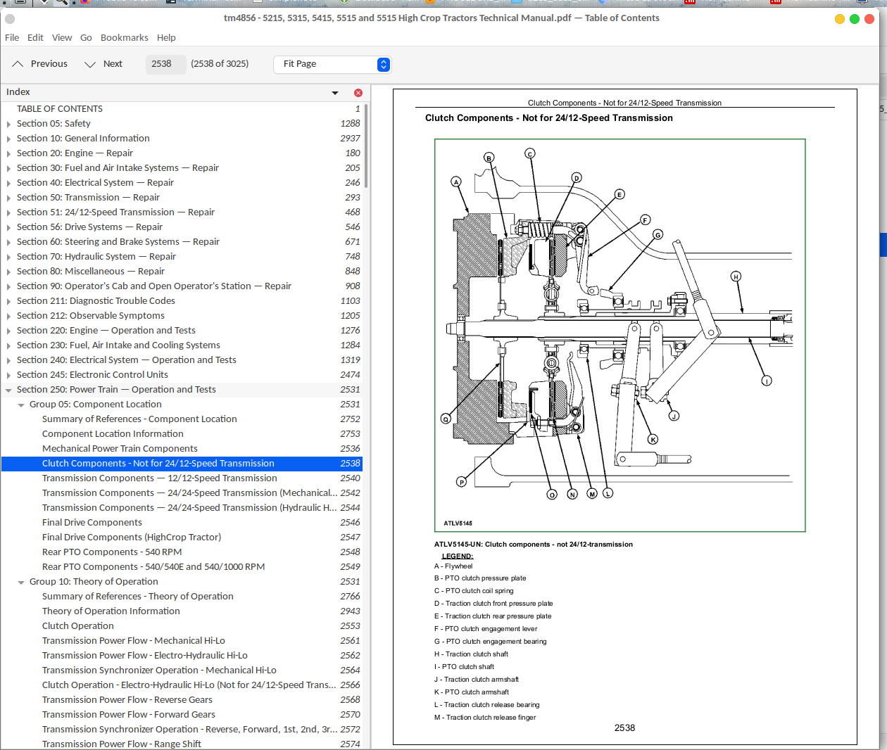
Clutch Components - Not for 24/12-Speed Transmission............2538
Transmission Components — 12/12-Speed Transmission............2540
Transmission Components — 24/24-Speed Transmission (Mechanical Hi-Lo Version)............2542
Transmission Components — 24/24-Speed Transmission (Hydraulic Hi-Lo Version)............2544
Final Drive Components............2546
Final Drive Components (HighCrop Tractor)............2547
Rear PTO Components - 540 RPM............2548
Rear PTO Components - 540/540E and 540/1000 RPM............2549
Group 10: Theory of Operation............2531
Summary of References - Theory of Operation............2766
Theory of Operation Information............2943
Clutch Operation............2553
Transmission Power Flow - Mechanical Hi-Lo............2561
Transmission Power Flow - Electro-Hydraulic Hi-Lo............2562
Transmission Synchronizer Operation - Mechanical Hi-Lo............2564
Clutch Operation - Electro-Hydraulic Hi-Lo (Not for 24/12-Speed Transmission)............2566
Transmission Power Flow - Reverse Gears............2568
Transmission Power Flow - Forward Gears............2570
Transmission Synchronizer Operation - Reverse, Forward, 1st, 2nd, 3rd and 4th Gear (Not for 24/12-Speed Transmission)............2572
Transmission Power Flow - Range Shift............2574
Rear PTO Operation............2576
540/540E and 540/1000 RPM Rear PTO Operation............2576
Differential Power Flow............2580
Differential Lock Operation............2582
Differential Lock Operation (Hydraulic Version)............2584
Final Drive Operation............2586
Final Drive Operation (HighCrop Traction)............2588
Front-Wheel Drive Operation - Mechanical Shifted............2590
Front-Wheel Drive Operation - Electro-Hydraulic Shifted (Only with Mechanical Hi-Lo)............2592
Group 15: Diagnosis, Tests and Adjustments............2532
Summary of References - Diagnosis, Tests and Adjustments............2597
Specifications............2884
Diagnostic Information............2964
Major Transmission Check............2600
Low Transmission Oil Level (Excessive Oil Leakage)............2605
Gears Clash, Shift Hard, or Will Not Engage............2606
Two Speeds Engage Together............2607
Transmission Will Not Stay in Gear............2608
Transmission Noisy............2609
PTO Noisy............2610
PTO Hard to Engage............2611
PTO Will Not Operate............2612
PTO Will Not Stay Engaged............2614
Excessive Differential Noise............2615
Differential Does Not Work............2616
Differential Lock Does Not Work............2617
Differential Chatters............2618
Axle Noise............2619
Axle Shaft Will Not Turn............2620
Front-Wheel Drive Lever Will Not Stay in ”Off” Position............2621
Checking Pressure at the Front-Wheel Drive Clutch............2622
Checking Pressure at the Hydraulic Differential Lock............2623
Noisy Front-Wheel Drive Operation............2624
Clutch Pedal Free Play Adjustment............2625
PTO Clutch Lever Adjustment............2627
Section 251: 24/12-Speed Transmission — Operation and Tests............2629
Group 05: Component Location............2629
Summary of References - Component Location (24/12-Speed Transmission)............2631
Components Other than Electro-Hydraulic Power Train............2632
Electro-Hydraulic Power Train Components............2633
Clutch Components - 24/12-Speed Transmission............2635
Group 10: Theory of Operation............2629
Summary of References - Theory of Operation (24/12-Speed Transmission)............2637
Clutch Operation (24/12-Speed Transmission)............2638
Transmission Power Flow - High clutch (24/12-Speed Transmission)............2641
Transmission Power Flow - Low clutch (24/12-Speed Transmission)............2643
Transmission Power Flow - Reverse clutch (24/12-Speed Transmission)............2645
Clutch Operation - High/Low/Reverse Clutch (Only for 24/12-Speed Transmission)............2647
Transmission Power Flow - Reverse Gears (Only for 24/12-Speed Transmission)............2650
Transmission Synchronizer Operation - Reverse, Forward, 1st, 2nd, 3rd and 4th Gear (Only for 24/12-Speed Transmission)............2652
Group 15: Diagnosis, Tests and Adjustments............2629
Summary of References - Diagnosis, Tests and Adjustments (24/12-Speed Transmission)............2655
Special Tools............2962
24/12-Speed Transmission - Operational Checkout............2629
24/12-Speed Transmission - Oil Pressure Tests............2629
Priority/Flow Regulator Valve - Adjustment............2667
Section 260: Steering and Brake Systems — Operation and Tests............2669
Group 05: Component Location............2669
Summary of References — Component Location............2672
Component Location Information............2753
Steering System Components............2674
Brake System Components............2677
Parking Brake Components for Electro-Hydraulic MFWD............2680
Trailer Brake System Components............2681
Group 10: Theory of Operation............2669
Summary of References — Theory of Operation............2942
General Information............2937
Steering System Operation............2685
Steering Valve Operation—Neutral and Manual Turning............2687
Steering Valve Operation—Power Turning............2689
Brake System Operation............2779
Brake Valve Operation - Brake Pedal Depressed............2693
Brake Valve Operation - Brake Pedal Released............2694
Trailer Brake System Operation............2779
Trailer Brake Valve Operation............2781
Parking Brake Operation for Electro-Hydraulic MFWD............2699
Group 15: Diagnosis, Tests and Adjustments............2669
Summary of References — Diagnosis, Tests and Adjustments............2955
Essential Tools............2703
Specifications............2884
Diagnostic Information............2964
Steering System Operational Check............2706
Steering System Diagnosis............2707
Steering Sluggish or Loss of Steering............2712
Brake System Operational Check............2713
Brake System Diagnosis............2714
Excessive Brake Pedal Leak-Down............2716
Excessive Brake Chatter............2717
Trailer Brake Valve Operational Check............2718
Trailer Brake Valve Operational Check (Italian Version)............2719
Trailer Brake Valve Troubleshooting............2720
Trailer Brake Valve Troubleshooting (Italian Version)............2723
Steering Pump Flow Test............2887
Steering Valve Relief Test............2726
Steering Cylinder Leakage Test............2727
Steering Valve Leakage Test............2728
Toe-In Check and Adjustment............2730
Toe-In Check and Adjustment (HighCrop Tractor)............2732
Toe-In Check and Adjustment (Front-Wheel Drive Axle)............2734
Steering Stop Adjustment............2736
Steering Stop Adjustment (Front-Wheel Drive Axle)............2737
Brake Pedal Adjustment............2738
Brake and Parking Brake Adjustment............2739
Bleed Brake System............2745
Section 270: Hydraulic System — Operation and Tests............2747
Group 05: Component Location............2747
Summary of References - Component Location............2752
Component Location Information............2753
Hydraulic System Components - Steering and Front-Wheel Drive (8/8 and 12/12-Speed Transmission)............2754
Hydraulic System Components - Steering and Front-Wheel Drive with Mechanical Hi-Lo (24/24-Speed Transmission)............2755
Hydraulic System Components - Steering and Front-Wheel Drive with Hydraulic Hi-Lo (24/24-Speed Transmission)............2757
Hydraulic System Components - Steering and Front-Wheel Drive (24/12-Speed Transmission)............2759
Rockshaft Control Lever Linkage Components............2761
SCVs with Levers and Flow Divider Valve............2762
Group 10: Theory of Operation............2747
Summary of References - Theory of Operation............2766
General Information............2937
Hydraulic System Operation............2769
Hydraulic Filter Operation............2771
Hydraulic Pump Operation............2773
Oil Cooler Operation............2775
PTO Clutch Hydraulic Operation............2777
Brake System Operation............2779
Trailer Brake Valve Operation............2781
Hydraulic System Operation - Steering and Front-Wheel Drive with Mechanical Hi-Lo (24/24-Speed Transmission)............2784
Hydraulic System Operation - Steering and Front-Wheel Drive with Hydraulic Hi-Lo (24/24-Speed Transmission)............2786
Hydraulic System Operation - Steering and Front-Wheel Drive (24/12-Speed Transmission)............2789
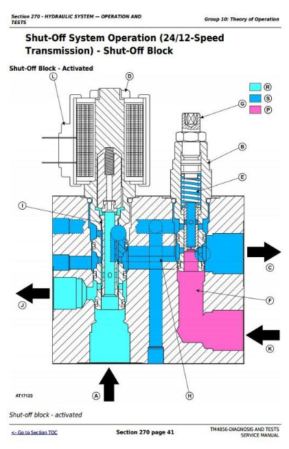
Shut-Off System Operation (24/12-Speed Transmission) - Shut-Off Block............2792
Shut-Off System Operation (24/12-Speed Transmission) - Shut-Off Valve............2796
Shut-Off System Operation (24/12-Speed Transmission) - Flow Control Valve............2799
Rockshaft Control Valve Operation - Neutral Position............2801
Rockshaft Control Valve Operation - Raise Position............2803
Rockshaft Control Valve Operation - Lower Position............2805
Rockshaft Draft - Sensing Operation............2807
Electro-Hydraulic Hitch Sensing Operation - Neutral Phase............2809
Electro-Hydraulic Hitch Sensing Operation - Loading Phase............2811
Electro-Hydraulic Hitch Sensing Operation - Discharge Phase............2814
Electro-Hydraulic Hitch Sensing II Operation - Neutral Phase............2816
Electro-Hydraulic Hitch Sensing II Operation - Loading Phase............2818
Electro-Hydraulic Hitch Sensing II Operation - Discharge Phase............2820
Double-Acting Selective Control Valve – Neutral Position............2822
Double-Acting Selective Control Valve – Position 1............2824
Double-Acting Selective Control Valve – Position 2............2826
Double-Acting Selective Control Valve - Float Position............2828
Convertible Selective Control Valve in Double-Acting Mode – Neutral Position............2830
Convertible Selective Control Valve in Double-Acting Mode – Return Position............2833
Convertible Selective Control Valve in Double-Acting Mode – Supply Position............2836
Convertible Selective Control Valve in Single-Acting Mode – Neutral Position............2839
Convertible Selective Control Valve in Single-Acting Mode – Return Position............2842
Convertible Selective Control Valve in Single-Acting Mode – Supply Position............2845
Double-Acting Sleeve Coupler Operation............2848
Flow Divider Valve with Solenoid Valve Operation............2850
Flow Divider Valve without Solenoid Valve Operation............2852
Group 15: Diagnosis............2748
Summary of References - Diagnosis............2855
Safety Precautions............2856
Diagnostic Information............2964
Hydraulic Oil Warm-Up Procedure............2858
Hydraulic System Major Test............2859
Hydraulic System Diagnosis............2862
Insufficient Pump Delivery............2868
Hydraulic Functions Too Slow............2869
Excessive Pump Pressure............2870
Slow Hydraulic Pump Response............2871
Excessive Pump Noise During Operation............2872
Rockshaft Does Not Lift or Lifts Slowly............2873
Rockshaft Does Not Lower or Lowers Slowly............2874
Neutral Position Unstable, Rockshaft Drops After Engine Shut-Down............2875
SCV Control Lever Does Not Return to Neutral Position............2876
SCV Does Not Return to Neutral Position - SCV With Detent Position............2877
SCV Does Not Remain In Detent Position - SCV With Detent Position............2878
Remote Cylinder Does Not Extend or Retract............2879
Remote Cylinder Settles Under Load............2880
Remote Cylinder Operates Too Fast or Too Slow............2881
Group 20: Tests............2749
Summary of References - Tests............2883
Specifications............2884
Hydraulic System Tests - With SCV............2885
Hydraulic System Tests............2886
Pump Flow Test............2887
SCV Relief Valve Test............2889
SCV Leakage Test............2890
EHS II Leakage Test............2891
Rockshaft Lift Cycle Test............2892
Group 25: Adjustments............2749
Summary of References - Adjustments............2895
Rockshaft Control Lever Friction Adjustment............2896
Rockshaft Sensitivity Adjustment............2897
Rockshaft Position Control Adjustment............2899
Rockshaft Draft Control Adjustment............2901
Electro-Hydraulic Hitch Sensing II Adjustment - Draft Sensor Rod Adjustment............2903
Rockshaft Safety and Relief Valve Adjustment............2905
Electro-Hydraulic Hitch Sensing Adjustment - Electro-Hydraulic Valve Adjustment............2907
Electro-Hydraulic Hitch Sensing Adjustment - Backstop Limit Switch Adjustment............2909
Electro-Hydraulic Hitch Sensing Adjustment - Rotary Position Sensor Adjustment............2910
Electro-Hydraulic Hitch Sensing Adjustment - Draft Sensor Adjustment............2911
SCV Relief Valve Adjustment............2912
Flow Divider Valve Adjustment............2913
Group 30: Hydraulic System Schematics............2749
Summary of References - Hydraulic System Schematics............2915
Hydraulic Symbols............2916
8/8 and 12/12-Speed Transmission (30 km/h / 18.5 mph) - Steering System without Front-Wheel Drive............2750
24/24-Speed Transmission (30 km/h / 18.5 mph and 40 km/h / 25 mph) - Steering System and Front-Wheel Drive with Mechanical Hi-Lo............2750
24/24-Speed Transmission (30 km/h / 18.5 mph and 40 km/h / 25 mph) - Steering System and Front-Wheel Drive with Electro-Hydraulic Hi-Lo............2750
24/12-Speed Transmission (40 km/h / 25 mph) - Steering System and Front-Wheel Drive with Electro-Hydraulic Management (EHM)............2750
SCV and Rockshaft with Flow Divider............2925
Section 280: Miscellaneous............2927
Group 10: Operational Checks............2927
Operational Test on Front-Wheel Drive Axle............2931
Checking Positive Front-Wheel Lead on Front-Wheel Drive Axle............2934
Section 290: Air-Conditioning System — Operation and Tests............2935
Group 05: Component Location............2935
General Information............2937
Air Conditioning System Components............2938
Heating System Components............2939
Group 10: Theory of Operation............2935
Summary of References — Theory of Operation............2942
Theory of Operation Information............2943
Principle of Heat Exchange............2944
R134a Refrigerant............2959
Operation of Air Conditioning System - Air-Flow............2946
Air-Conditioning System Operation............2948
Compressor............2950
Condenser............2951
Receiver-Drier............2952
Expansion Valve............2953
Group 15: Diagnosis, Tests and Adjustments............2935
Summary of References — Diagnosis, Tests and Adjustments............2955
Safety Equipment............2956
In an Emergency............2957
Storage of Refrigerant Containers............2958
R134a Refrigerant............2959
Important Note............2960
Special or Essential Tools............2961
Special Tools............2962
Diagnostic Information............2964
Air Conditioning System Diagnosis............2965
Pressure Deviations............2974
Air Conditioning System Trouble-Shooting............2976
Failure Of Mechanical Type............2980
Section 299: Special Tools............2982
Group 05: Special Tools (Dealer-Fabricated)............2982
Summary of References — Dealer-Manufactured Tools............2985
Adapter............2986
Cone Point Adjustment Tools............2987
Draft Control Adjusting Tool............2989
Seal Ring Replacement Kit - Tool 1............2990
Seal Ring Replacement Kit - Tool 2............2991
Group 10: Special Tools and Test Equipment............2982
Summary of References - Special Tools and Test Equipment............2993
D01019AA - Single-Speed Hydraulic Hand Pump Assembly............2994
D01072AA - Bushing, Bearing, and Seal Driver Set............2995
D01210AA - Slide Hammer Puller............2996
FKM10472 - Flow Measurement System............2997
FKM10475 - Adjusting Tool............2998
FKM10470 - Pressure measuring system (stage 1)............2999
FKM10471 - Pressure measuring system (stage 2)............3000
JDE83 - Flywheel Turning Tool............3001
JDG19 - Lifting Eyes............3002
JDG1337 - Clutch Repair Fixture............3003
JDG1375 - Clutch Finger Height Gauge............3004
JT05791A - Multimeter............3005
JT05800 - Digital Thermometer............3006
KJD10491 - Diagnostic Interface Cable............3007
KJD10492 - Puller Tool............3008
KJD10493 - Pressure Tool............3009
KJD10494 - Tensioning Tool............3010
KJD10178-8B - Square Tube............3011
KJD10178C - Cab Tilting Device............3012
CA715825 - Bearing Driver............3013
CA119034 - Seal Ring Driver............3014
CA715824 - Seal Ring Driver............3015
CA715844 - Bearing Cup Driver............3016
CA715836 - Seal Ring Driver............3017
CA715826 - Seal Ring Driver............3018
CA715827 - Bearing Cup Driver............3019
John Deere Tractors 5215, 5315, 5415, 5515 High Crop Diagnosis & Tests Service Manual (TM4856)
![]()