
John Deere Tractors 5215F, 5315F, 5515F, 5615F, 5215V, 5315V, 5515V, 5615V Diagnostic and Repair Service Manual (TM4861)
Complete All Inclusive Technical Manual with electrical wiring diagrams for John Deere Tractors 5215F, 5315F, 5515F, 5615F, 5215V, 5315V, 5515V, 5615V, with all the workshop information to maintain, diagnose, repair, and rebuild like professional mechanics (Diagnose, Operation, Tests, Repair, Service, Troubleshooting).
John Deere 5215F/V, 5315F/V, 5515F/V and 5615F/V Tractors (European Version) workshop technical service manual includes:
* Numbered table of contents easy to use so that you can find the information you need fast.
* Detailed sub-steps expand on repair procedure information
* Numbered instructions guide you through every repair procedure step by step.
* Troubleshooting and electrical service procedures are combined with detailed wiring diagrams for ease of use.
* Notes, cautions and warnings throughout each chapter pinpoint critical information.
* Bold figure number help you quickly match illustrations with instructions.
* Detailed illustrations, drawings and photos guide you through every procedure.
* Enlarged inset helps you identify and examine parts in detail.
John Deere Tractors 5215F, 5315F, 5515F, 5615F, 5215V, 5315V, 5515V, 5615V Diagnostic and Repair Service Manual (TM4861)
tm4861 - John Deere 5215F/V, 5315F/V, 5515F/V and 5615F/V Tractors (European Version) Diagnostic and Repair Technical Manual.pdf
tm4861 - John Deere 5215F/V, 5315F/V, 5515F/V and 5615F/V Tractors (European Version) Diagnostic and Repair Technical Manual.epub
Total Pages: 3,058 pages
File Format: PDF (bookmarked, ToC, Searchable, Printable, high quality) & EPUB/MOBI/AZW for Kindle/iPad/iPhone/Android.
Language: English
MAIN SECIONS
Foreword
Edition
Safety
Safety Measures
General Information
Specifications
Tune-Up
Predelivery Inspection
Engine - Repair
Remove and Install Engine Components
Fuel and Air Intake Systems - Repair
Speed Control Linkage
Fuel System
Air Intake System
Electrical System - Repair
Battery, Starting Motor and Alternator
Switches and Sensors
Transmission - Repair
Remove and Install Power Train Components
Clutch
Hi-Lo System (24/24-Speed Transmission)
Transmission
24/12-Speed Transmission - Repair
Removal and Installation of 24/12-Speed Transmission Components
Clutch - 24/12-Speed Transmission
El.-Hydr. High/Low/Reverse Clutch (24/12-Speed Transmission)
Drive Systems - Repair
Remove and Install Components
Front-Wheel Drive Clutch - Transmission
Differential
Final Drives
Power Take-Off
Housing Sensors Assembly
Steering and Brake Systems - Repair
Steering System
Brake System
Hydraulic System - Repair
Hydraulic Pump and Filter
Hitch
Three-Point Hitch
Selective Control Valves
Miscellaneous - Repair
Remove and Install Components
Front Axle
Front and Rear Wheels
Trailer Mounting and Swinging Drawbar
Fenders
Operator`s Cab and Open Operator`s Station - Repair
Remove and Install Operator`s Cab/Open Operator`s Station
Controls and Instruments
Air-Conditioning System
Heating System
Operator`s Cab
Open Operator`s Station
Operator`s Seat and Support
Diagnostic Trouble Codes
Electro-Hydraulic Management
Electronic Hitch Sensing
Observable Symptoms
Fuel and Air Intake System
Electrical System
Power Train
PowrReverser Transmission
Steering and Brakes
Front-Wheel Drive
Engine - Operation and Tests
Operational Check-Out
Tests and Adjustments
Fuel, Air Intake and Cooling Systems
Tests and Adjustments
Theory of Operation
Electrical System - Operation and Tests
SE01 - Motor Starting and Charging System
SE02 - Instrument Panel
SE03 - Horn
SE06 - Lighting System
SE07 - Work Lights
SE09 - Radio, Dome and Console Light
SE10 - Fan and Air-Conditioning System
SE11 - Wiper and Washer System
SE13 - Beacon Light
SE14 - Power Outlet
SE15A - Electronic Hitch Sensing (EHS)
SE15B - Electronic Hitch Sensing (EHS II)
SE16A - Hazard Warning and Turn Signal Lights
SE16B - PTO System
SE16C - Front-Wheel Drive, Differential Lock and Braking System
SE21 - Flow Divider Valve
SE26A - Electro-Hydraulic Management (EHM)
SE26B- Electro-Hydraulic Management (EHM II)
SE27 - Electro-Hydraulic Hi-Lo
Component Information - Connectors
Component Information - Wiring Harnesses
Component Information - Electrical Parts
Component Information - Ground Connection
Wiring Diagrams
Electronic Control Units
Operation and General Information on Diagnostics
EHM-Electrohydraulic Management
EHS-Electronic Hitch Sensing
Power Train - Operation and Tests
Component Location
Theory of Operation
Diagnostics, Tests and Adjustments
24/12-Speed Transmission - Operation and Tests
Component Location
Theory of Operation
Diagnostics, Tests and Adjustments
Steering and Brake Systems - Operation and Tests
Component Location
Theory of Operation
Diagnostics, Tests and Adjustments
Hydraulic System - Operation and Tests
Component Location
Theory of Operation
Diagnostics
Tests
Adjustments
Hydraulic System Schematics
Miscellaneous
Operational Checks
Air-Conditioning System - Operation and Tests
Component Location
Theory of Operation
Diagnostics, Tests and Adjustments
Special Tools
Special Tools (Dealer-Fabricated)
Special Tools and Test Equipment
tm4861 - 5215F/V, 5315F/V,5515F/V and 5615F/V Tractors -: (European Version)
Table of Contents
Foreword
Edition
Section 05: Safety
Group 05: Safety Measures
Recognize Safety Information
Understand Signal Words
Follow Safety Instructions
Prepare for Emergencies
Wear Protective Clothing
Protect Against Noise
Handle Fuel Safely—Avoid Fires
Fire Prevention
In Case of Fire
Avoid Static Electricity Risk When Refueling
Use Foldable ROPS and Seat Belt Properly
Stay Clear of Rotating Drivelines
Use Steps and Handholds Correctly
Read Operator’s Manuals for ISOBUS Controllers
Use Seat Belt Properly
Vibration
Operating the Tractor Safely
Avoid Backover Accidents
Limited Use in Forestry Operation
Operating the Loader Tractor Safely
Passenger Seat
Use Safety Lights and Devices
Use Caution On Slopes and Uneven Terrain
Freeing a Mired Machine
Avoid Contact with Agricultural Chemicals
Handle Agricultural Chemicals Safely
Handling Batteries Safely
Avoid Heating Near Pressurized Fluid Lines
Remove Paint Before Welding or Heating
Handle Electronic Components and Brackets Safely
Practice Safe Maintenance
Clean Exhaust Filter Safely
Work In Ventilated Area
Support Machine Properly
Prevent Machine Runaway
Park Machine Safely
Transport Tractor Safely
Service Cooling System Safely
Service Accumulator Systems Safely
Service Front-Wheel Drive Tractor Safely
Tightening Wheel Retaining Bolts/Nuts
Avoid High-Pressure Fluids
Do Not Open High-Pressure Fuel System
Store Attachments Safely
Decommissioning: Proper Recycling and Disposal of Fluids and Components
“Important” - Information
”Note” Information
Section 10: General Information
Group 05: Specifications
Summary of References — Specifications
Engine
Transmission
Front-Wheel Drive Clutch
Hydraulic System
Electrical System
Capacities
Sound Level
Fuel System
Brakes
Three-Point Hitch
Loads and Weights
Towable Loads
Shipping Weights
Axle Load Limits and Maximum Permissible Weights, F-Type Tractors
Axle Load Limits and Maximum Permissible Weights, V-Type Tractors
Load Capacity Of Tires
Load Capacity of Tires With Front Loader
Observe Rear Wheel Tread Width Limitations
Metric Bolt and Screw Torque Values
Unified Inch Bolt and Screw Torque Values
Diesel Fuel
Handling and Storing Diesel Fuel
Do Not Use Galvanized Containers
Fill Fuel Tank
Diesel Engine Break-In Oil — Non-Emissions Certified and Certified Tier 1, Tier 2, Tier 3, Stage I, Stage II, and Stage III
Diesel Engine Oil — Tier 2 and Stage II
Transmission and Hydraulic Oil
Front-Wheel Drive Axle Oil
Grease
Oil Filters
Lubricant Storage
Mixing of Lubricants
Diesel Engine Coolant
Operating in Warm Temperature Climates
Alternative and Synthetic Lubricants
Serial Number Plates
Product Identification Number Location
Engine Serial Number
Fuel Injection Pump Serial Number Location
Alternator Serial Number Location
Power Steering Valve Serial Number Location
Air-Conditioning Compressor Serial Number Location
Transmission Serial Number Location
Front Axle (2WD) Serial Number Location
Front-Wheel Drive Serial Number
Group 10: Tune-Up
Summary of References - Tune-Up
Using High-Pressure Washers
Preliminary engine test
Clean Radiator and Oil Cooler
Cleaning Air Conditioning System Condenser (If Equipped)
Check Hoses and Hose Clamps
Clean Engine Crankcase Vent Tube
Cleaning the Dust Unloading Valve
Engine Air Filter
Cleaning the Primary Filter Element
Cleaning a Dusty Element
Secondary (Safety) Element
Cleaning Cab Air Filters
Check Belt Wear and Tension
Check Engine Oil Level
Check Coolant Level
Check Transmission/Hydraulic System Oil Level
Checking the Fuel Filter
Bleeding Fuel System
Adjust Throttle Friction
Starting Motor
Battery - Checking Specific Gravity
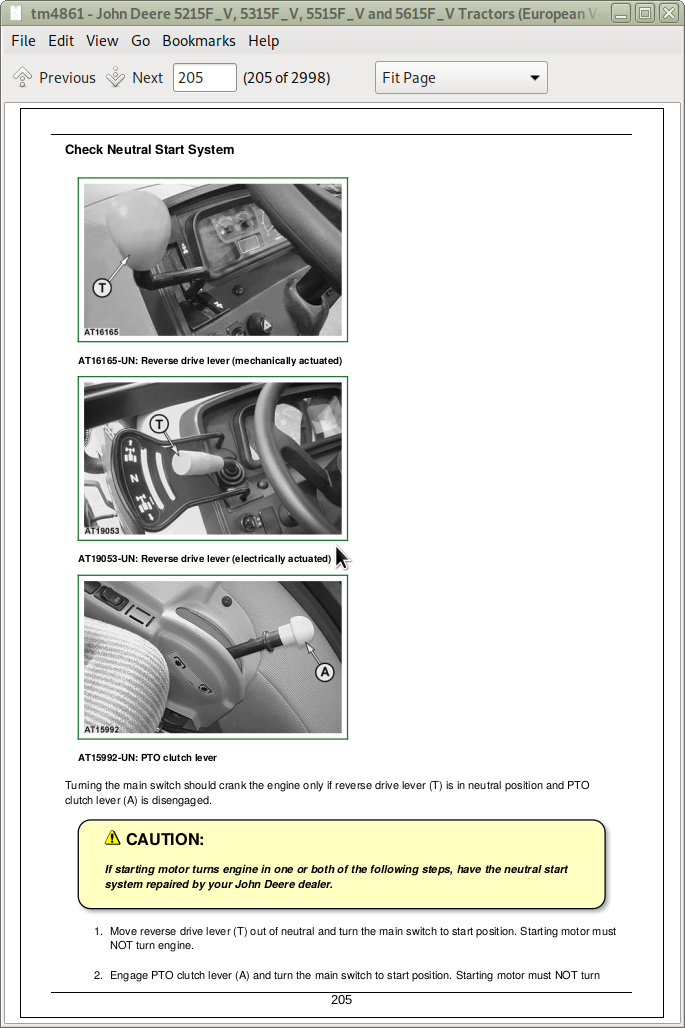
Check Neutral Start System
Check Setting of Head Lights and Work Lights
Check Lights
Final Engine Check
Tractor Operation Check
Group 15: Predelivery Inspection
Predelivery Inspection
Section 20: Engine — Repair
Group 00: Remove and Install Engine Components
Summary of References — Remove and Install Engine Components
Engine Repair
Essential Tools
Specifications
Remove Engine
Install Engine
Water Pump Repair
Remove and Inspect Radiator
Install Radiator
Remove and Install Oil Cooler
Replace Thermostat
Section 30: Fuel and Air Intake Systems — Repair
Group 05: Speed Control Linkage
Summary of References — Speed Control Linkage
Remove and Install Speed Control Linkage for Tractors up to Serial. No. 208300
Inspect and Repair Speed Control Linkage for Tractors up to Serial. No. 208300
Adjust Engine Idle Speed for Tractors up to Serial. No. 208300
Adjust Throttle Lever for Tractors up to Serial. No. 208300
Adjust Hand Throttle Lever and Accelerator Pedal for Tractors from Serial. No. 208301
Recondition Hand Throttle Lever and Accelerator Pedal for Tractors from Serial. No. 208301
Group 10: Fuel System
Summary of References — Fuel System
Injection Pump, Nozzle and Governor Repair
Remove Fuel Tank (Narrow Version)
Install Fuel Tank (Narrow Tractors)
Replace Fuel Filter
Replace Primary Fuel Filter
Replace Fuel Transfer Pump
Replace Adapter in Fuel Line
Bleed Fuel System
Group 15: Air Intake System
Summary of References — Air Intake System
Turbocharger Repair
Remove and Install the Air Filter Element
Remove and Install Air Intake Hoses
Replace Air Filter Restriction Switch
Section 40: Electrical System — Repair
Group 05: Battery, Starting Motor and Alternator
Summary of References — Battery, Starting Motor and Alternator
Starting Motor Repair
Remove and Install Battery
Remove and Install Starting Motor
Alternator/Regulator Repair
Replace Alternator/Regulator
Checking Belt Wear and Tension
Group 10: Switches and Sensors
Summary of References — Switches and Sensors
Replace Air Filter Restriction Switch B02
Replace Fuel Level Sensor B03
Replace Engine Oil Pressure Switch B04
Replace Parking Brake Switch B05
Replace Ground Speed Sensor B06
Replace PTO Speed Selection Switch B07
Replace Neutral Start Switch B36
Replace Coolant Temperature Sensor B56
Replace Clutch Pedal Potentiometer B65
Replace Engine Speed Sensor B72
Replace Brake Pedal Switches B112
Replace Main Switch S01
Replace Turn Signal Light Switch S08
Replace Light and Horn Switch S09
Replace PTO Mode Switch S21
Replace Clutch Pedal Switch S72
Replace Hazard Warning Light Switch S106
Replace Fuel Shut-Off Solenoid Valve Y13
Replace Instrument Panel
Section 50: Transmission — Repair
Group 00: Remove and Install Power Train Components
Summary of References — Remove and Install Power Train Components
Specifications
Separate Engine from Clutch Housing
Install Engine to Clutch Housing
Separate Clutch Housing from Transmission - Not for 24/12-Speed Transmission
Install Clutch Housing to Transmission - Not for 24/12-Speed Transmission
Replace Clutch Housing Seal - 12/12 Speed Transmission
Replace Clutch Housing Seal - 24/24 Speed Transmission
Remove and Install Rear PTO Drive Shaft
Group 05: Clutch
Summary of References — Clutch
Specifications
Inspect and Repair Clutch Pedal and Linkage - Not for 24/12 Speed Transmission
Remove and Install Clutch Assembly - Not for 24/12 Speed Transmission
Disassemble and Inspect Clutch Assembly - Not for 24/12 Speed Transmission
Assemble Clutch Assembly - Not for 24/12 Speed Transmission
Traction Clutch Finger Adjustment - Not for 24/12 Speed Transmission
PTO Clutch Finger Adjustment - Not for 24/12 Speed Transmission
Remove and Inspect Clutch Release Mechanism - Not for 24/12 Speed Transmission
Install Clutch Release Mechanism - Not for 24/12 Speed Transmission
Group 10: Hi-Lo System (24/24-Speed Transmission)
Summary of References - Hi-Lo Clutch (24/24-Speed Transmission)
Specifications
Remove and Inspect Mechanical Hi-Lo Drive
Install Mechanical Hi-Lo Drive
Disassemble, Inspect and Assemble Mechanical Hi-Lo Shift Shaft Assembly
Disassemble, Inspect and Assemble Mechanical Hi-Lo Synchronizer
Disassemble, Inspect and Assemble Mechanical Hi-Lo Drive Shaft
Disassemble, Inspect and Assemble Mechanical Hi-Lo Reduction Shaft
Inspect and Repair Mechanical Hi-Lo Shift Lever
Seal Ring Replacement of Hydraulic Hi-Lo Clutch Drive Shaft
Remove and Inspect Hydraulic Hi-Lo Clutch Assembly
Install Hydraulic Hi-Lo Clutch Assembly
Disassemble, Inspect and Assemble Hydraulic Hi-Lo Clutch
Disassemble, Inspect and Assemble Hydraulic Hi-Lo Drive Shaft
Group 20: Transmission
Summary of References — Transmission
Specifications
Remove and Install Transmission
Repair Gear and Range Shift Levers
Remove, Inspect and Install Range Shaft
Range Shaft End Play Adjustment
Remove, Inspect and Install Primary and Reverse Shafts
Primary Shaft End Play Adjustment
Remove, Inspect and Install Pinion Shaft
Pinion Shaft Cone Point Adjustment
Pinion Bearing Preload Adjustment
Remove, Inspect and Install Secondary Shaft
Secondary Shaft End Play Adjustment
Section 51: 24/12-Speed Transmission — Repair
Group 00: Removal and Installation of 24/12-Speed Transmission Components
Summary of References — Remove and Install 24/12-Speed Transmission Components
Separate Clutch Housing from Transmission - Only for 24/12-Speed Transmission
Install Clutch Housing to Transmission - Only for 24/12-Speed Transmission
Replace Clutch Inner Control Seal - Only for 24/12-Speed Transmission
Remove and Install Air Pump
Remove and Install Lube Oil Valve
Group 05: Clutch - 24/12-Speed Transmission
Summary of References - 24/12-Speed Transmission Clutch
Specifications
Remove and Install Clutch Assembly - Only for 24/12 Speed Transmission
Disassemble and Inspect Clutch Assembly - Only for 24/12-Speed Transmission
Assemble Clutch Assembly - Only for 24/12-Speed Transmission
PTO Clutch Finger Adjustment - Only for 24/12-Speed Transmission
Remove and Inspect Clutch Release Mechanism - Only for 24/12-Speed Transmission
Install Clutch Release Mechanism - Only for 24/12-Speed Transmission
Group 15: El.-Hydr. High/Low/Reverse Clutch (24/12-Speed Transmission)
Summary of References - Electro-Hydraulic High/Low/Reverse Clutch (24/12-Speed Transmission)
Remove Electro-Hydraulic High/Low/Reverse Clutch Assembly (24/12-Speed Transmission)
Install Electro-Hydraulic High/Low/Reverse Clutch Assembly (24/12-Speed Transmission)
Replace Clutch Housing Seal - Only for 24/12-Speed Transmission
Seal Ring Replacement of Low/Reverse Clutch Drive Shaft
Disassemble, Inspect and Assemble Electro-Hydraulic High Clutch (24/12-Speed Transmission)
Disassemble, Inspect and Assemble Electro-Hydraulic Low Clutch (24/12-Speed Transmission)
Disassemble, Inspect and Assemble Electro-Hydraulic Reverse Clutch (24/12-Speed Transmission)
Section 56: Drive Systems — Repair
Group 00: Remove and Install Components
Summary of References — Remove and Install Components
Specifications
Remove and Install Front-Wheel Drive Clutch
Remove and Install Differential Assembly
Remove and Install Final Drive Assembly
Group 15: Front-Wheel Drive Clutch — Transmission
Summary of References — Front-Wheel Drive Clutch
Service Equipment and Tools
Specifications
Disassemble and Inspect Front-Wheel Drive Clutch — Hydraulic Operated
Front-Wheel Drive Clutch Cross Section — Hydraulic Operated
Assemble Front-Wheel Drive Clutch — Hydraulic Operated
Disassemble and Inspect Front-Wheel Drive Clutch — Hydraulic Operated with Park Brake
Front-Wheel Drive Clutch Cross Section – Hydraulic Operated with Park Brake
Assemble Front-Wheel Drive Clutch – Hydraulic Operated with Park Brake
Disassemble and Inspect Front-Wheel Drive Clutch — Mechanically Operated
Front-Wheel Drive Clutch Cross Section — Mechanically Operated
Assemble Front-Wheel Drive Clutch — Mechanically Operated
Group 20: Differential
Summary of References — Differential
Essential Tools
Service Equipment and Tools
Specifications
Disassemble, Inspect and Assemble Two Pinion Differential Assembly
Two Pinion Differential Bearing Preload Adjustment
Two Pinion Differential Backlash Adjustment
Disassemble, Inspect and Assemble Four-Pinion Differential Assembly
Four Pinion Differential Backlash Adjustment
Four Pinion Differential Bearing Preload Adjustment
Inspect and Repair Differential Lock Pedal and Linkage
Inspect and Repair Hydraulic Differential Lock and Linkage
Remove, Inspect and Install Differential Lock Assembly
Group 25: Final Drives
Summary of References — Final Drives
Specifications
Remove and Inspect Planetary Drive Assembly
Install Planetary Drive Assembly
Remove, Inspect and Install Axle Shaft Assembly (3-Cylinder Tractors)
Remove, Inspect and Install Axle Shaft Assembly (4-Cylinder Tractors)
Group 30: Power Take-Off
Summary of References — Power Take-Off
Service Equipment and Tools
Inspect and Repair Rear PTO Clutch Lever and Linkage
Inspect and Repair Rear PTO Engagement Lever and Linkage
Disassemble, Inspect and Assemble PTO Shift Lever Assembly
Disassemble, Inspect and Assemble Rear PTO Engagement Control
Disassemble, Inspect and Assemble Rear PTO Engagement Sleeve
Disassemble, Inspect and Assemble Rear PTO Drive Shaft Assembly
Group 35: Housing Sensors Assembly
Disassemble, Inspect and Assemble Transmission Housing Sensors
Section 60: Steering and Brake Systems — Repair
Group 05: Steering System
Summary of References — Steering System
Specifications
Remove and Install Steering Column and Valve
Disassemble and Inspect Steering Valve
Assemble Steering Valve
Remove and Install Steering Cylinder
Disassemble, Inspect and Assemble Steering Cylinder
Remove, Inspect and Install Tie Rod Assembly
Inspect and Replace Steering Hydraulic Lines
Group 10: Brake System
Summary of References — Brake System
Specifications
Change Brake System Oil
Remove and Install Brake Valve and Pedals
Disassemble and Inspect Brake Pedals
Disassemble Brake Valve
Brake Valve Cross Section
Assemble Brake Valve
Remove and Inspect Brakes
Install Brakes
Remove and Install Trailer Brake Valve
Disassemble and Inspect Trailer Brake Valve
Inspect and Replace Brake Hydraulic Lines
Remove, Inspect and Install Hydraulic Actuator
Remove, Inspect and Install Brake Linkage
Remove, Inspect and Install Parking Brake Lever
Remove, Inspect and Install Parking Brake Linkage
Remove, Inspect and Install Parking Brake Lever and Linkage on Electro-Hydraulic MFWD
Trailer Brake Valve System Components
Remove and Inspect Trailer Brake Valve
Install Trailer Brake Valve and Lines
Section 70: Hydraulic System — Repair
Group 05: Hydraulic Pump and Filter
Summary of References — Hydraulic Pump and Filter
Specifications
Remove and Install Hydraulic Pump
Remove Hydraulic Pump External Components
Disassemble and Inspect Hydraulic Pump
Assemble Hydraulic Pump
Install Hydraulic Pump External Components
Remove and Install Hydraulic Filter/Manifold
Inspect and Replace Hydraulic Suction Lines
Inspect and Replace Hydraulic Supply Lines
Group 10: Hitch
Summary of References — Rockshaft
Essential Tools
Specifications
Inspect and Repair Rockshaft Control Lever and Linkage
Remove, Inspect and Install Rockshaft Control Valve
Remove, Inspect and Install EHS
Remove, Inspect and Install EHSII
Remove, Inspect and Install Sensing Linkage
Sensing Spring Adjustment
Safety and Relief Valve Adjustment
Remove and Install Rockshaft Case
Remove, Inspect and Install Rockshaft Lift Arms and Cylinder
Remove Rockshaft Control Linkage
Inspect and Repair Rockshaft Control Linkage
Install Rockshaft Control Linkage
Rockshaft Sensitivity Adjustment
Rockshaft Position Control Lever Adjustment
Rockshaft Draft Control Lever Adjustment
Distributor Control Valve Adjustment
Group 15: Three-Point Hitch
Summary of References — Three-Point Hitch
Specifications
Inspect and Repair Draft Links
Inspect and Repair Adjustable Lift Link
Inspect and Repair Hydraulic Adjustable Lift Link
Inspect and Repair Center Link
Group 20: Selective Control Valves
Summary of References — Selective Control Valves
Selective Control Valve and Lever Assembly
Remove and Install Selective Control Valve (SCV)
Remove and Install Selective Control Valve (SCV) — Tractors With Mid Mounted Couplers
Disassemble, Inspect and Assemble Selective Control Valve
Disassemble, Inspect and Assemble Selective Control Valve Lever
Selective Control Valve Levers — Exploded View
Remove and Install Flow Divider Valve
Section 80: Miscellaneous — Repair
Group 00: Remove and Install Components
Summary of References — Remove and Install Components (Miscellaneous)
Specifications
Remove Hood and Side Panels
Install Hood and Side Panels
Remove and Install Front Axle
Remove, Inspect and Install Front Axle Drive Shaft
Remove and Install Front Axle Drive Assembly
Group 10: Front Axle
Summary of References — Front Axle
Specifications
Inspect and Replace Pivot Pin and Bushings
Remove and Install Spindle Assembly
Inspect and Replace Spindle Shaft Bushings
Inspect and Replace Front Wheel Bearings
Group 15: Front and Rear Wheels
Remove and Install Front or Rear Wheels
Group 20: Trailer Mounting and Swinging Drawbar
Summary of References - Trailer Mounting and Swinging Drawbar
Checking the Manually-Operated Hitch (EEC Type) for Wear
Checking the Manually-Operated Hitch (CUNA Type) for Wear (Italy, Spain and Portugal Only)
Checking the Tow Hook for Wear
Checking the Swinging Drawbar for Wear
Guide Rails for Height-Adjustable Trailer Hitch
Swinging Drawbar
Group 25: Fenders
Remove and Install Fenders (Cab Tractors)
Section 90: Operator's Cab and Open Operator's Station — Repair
Group 00: Remove and Install Operator's Cab/Open Operator's Station
Summary of References — Remove and Install Operator's Cab/Open Operator's Station
Remove Operator's Cab
Install Operator's Cab
Remove Open Operator's Station
Install Open Operator's Station
Group 05: Controls and Instruments
Summary of References — Controls and Instruments
Remove Control Lever Moldings
Install Control Lever Moldings
Remove Instrument Panel
Install Instrument Panel
Remove and Install EHS Control Panel
Remove and Install EHS II Control Panel
Remove and Install EHM Control Unit
Remove and Install EHM II Control Unit
Group 15: Air-Conditioning System
Summary of References — Air-Conditioning System
Essential Tools
Specifications
Torques for Tightening Refrigerant Hoses
Safety At Work
Handling Refrigerant
In An Emergency
Safety Equipment
Storage of Refrigerant Containers
R134a Refrigerant
Important
Discharging the System
Evacuating the System
Filling With Refrigerant Oil
Filling the System
Topping Up a Partly Discharged System
Leakage Test
Replace Air-Conditioning Receiver-Drier
Remove, Inspect and Install Air-Conditioning Condenser
Remove, Inspect and Install Air-Conditioning Compressor (3-Cylinder Version)
Remove, Inspect and Install Air-Conditioning Compressor (4-Cylinder Version)
Checking Level in the Compressor
Air-Conditioning Evaporator — Parts
Remove and Install Air-Conditioning Evaporator
Group 20: Heating System
Summary of References — Heating System
Remove, Inspect and Install Heater Components
Remove, Inspect and Install Blower Motor
Group 25: Operator's Cab
Summary of References — Operator's Cab
Specifications
Remove and Install Sun Visor
Remove and Install Front Windshield
Front Windshield, Exploded View
Remove and Install Lower Front Windows
Lower Front Windows, Exploded View
Remove and Install Cab Door
Remove and Install Inner Handle
Cab Door, Exploded View
Remove and Install Rear Side Cab Windows
Rear Side Cab Windows, Exploded View
Remove and Install Rear Window
Rear Window, Exploded View
Remove and Install Cab Recirculating/Fresh Air Filter
Group 30: Open Operator's Station
Summary of References — Open Operator's Station
Remove and Install 2-post ROPS
Group 35: Operator's Seat and Support
Summary of References - Operator's Seat and Support
Remove and Install Operator's Seat and Support
Section 211: Diagnostic Trouble Codes
Group EHM: Electro-Hydraulic Management
EHM Trouble Codes - Summary of References
Error and Calibration Codes
EHM 00 - Control Unit Internal Fault (EHM or EHM II)
EHM 12 - Transmission Oil Temperature Sensor, Signal Too High (EHM or EHM II)
EHM 13 - Transmission Oil Temperature Sensor, Signal Too Low (EHM II)
EHM 15 - Clutch Pedal Potentiometer, Signal Voltage Too Low (EHM or EHM II)
EHM 16 - Clutch Pedal Potentiometer, Signal Voltage Too High (EHM or EHM II)
EHM 17 - Clutch Pedal Potentiometer Signal And Clutch Pedal Switch Status Do Not Match (EHM or EHM II)
EHM 18 - Forward High Clutch Solenoid Valve, Shorted Or Open Circuit (EHM or EHM II)
EHM 19 - Forward Low Clutch Solenoid Valve, Shorted Or Open Circuit (EHM or EHM II)
EHM 20 - Reverse Clutch Solenoid Valve, Shorted Or Open Circuit (EHM or EHM II)
EHM 21 - Clutch Valve Solenoids (Common Code For All Clutches) (EHM or EHM II)
EHM 22 - Forward High Clutch Solenoid Valve, Supply Pin Shorted To 12 Volts (EHM or EHM II)
EHM 23 - Forward Low Clutch Solenoid Valve, Supply Pin Shorted To 12 Volts (EHM or EHM II)
EHM 24 - Reverse Clutch Solenoid Valve, Supply Pin Shorted To 12 Volts (EHM or EHM II)
EHM 25 - Reverse Drive Lever Malfunction, Forward And Reverse Signals Received Simultaneously (EHM or EHM II)
EHM 26 - Reverse Drive Lever Malfunction, Forward And Neutral Signals Received Simultaneously (EHM or EHM II)
EHM 27 - Reverse Drive Lever Malfunction, Reverse And Neutral Signals Received Simultaneously (EHM or EHM II)
EHM 28 - EHM Supply Critical - Voltage Low (EHM or EHM II)
EHM 29 - EHM Supply Critical - Voltage High (EHM II)
EHM 30 - Forward High or Reverse Clutch Valve Solenoid, Shorted to Ground (EHM II)
EHM 35 - EHM 5-Volt Sensor Supply Critical - Voltage High (EHM II)
EHM 36 - EHM 5-Volt Sensor Supply Critical - Voltage Low (EHM II)
EHM 49 - Reverse Drive Lever Malfunction, Forward, Neutral and Reverse Signals Received Simultaneously (EHM II)
EHM dLEr - Differential Lock Disengagement Solenoid over current EHM II
EHM FdEr - Four Wheel Drive Disengagement Solenoid Shorted to Ground EHM II
EHM MrOE - Shut-Off Solenoid Valve of Shut-Off System Open EHM II
EHM MrrF - Shut Off Solenoid Valve Supply Pin Shorted To 12 Volts EHM II
EHM MrSF - Shut Off Solenoid Valve Supply Pin Shorted to Ground EHM II
EHM OIL - Transmission Oil Temperature Too High EHM II
EHM OILH - Transmission Oil Temperature Reached Maximum Limit EHM II
EHM OILL - Transmission Oil Temperature Reached Minimum Limit EHM II
EHM CFSE - Oil Filter Restriction Sensor Malfunction EHM II
EHM FHSE - Forward High Clutch Pressure Sensor Malfunction EHM II
EHM FLSE - Forward LOw Clutch Pressure Sensor Malfunction EHM II
EHM MrCE - Shut-Off Solenoid Valve Malfunction EHM II
EHM MrSE - Shut-Off Solenoid Valve Malfunction EHM II
EHM rESE - Reverse Clutch Pressure Sensor Malfunction EHM II
EHM StOP - System Initial Check EHM II
EHM DAtA - Calibration Parameters Out Of Range EHM II
EHM CFCL - Oil Filter Restriction Sensor Malfunction EHM II
EHM FHCE - Forward High Clutch Solenoid Valve Malfunction EHM II
EHM FHOE - Forward High Clutch Solenoid Valve Malfunction EHM II
EHM FLCE - Forward Low Clutch Solenoid Valve Malfunction EHM II
EHM FLOE - Forward Low Clutch Solenoid Valve Malfunction EHM II
EHM rECE - Reverse Clutch Solenoid Valve Malfunction EHM II
EHM rEOE - Reverse Clutch Solenoid Valve Malfunction EHM II
EHM PEd - Clutch Slipping For Excessive Time EHM II
EHM nEU - Message
Group EHS: Electronic Hitch Sensing
Diagnosis (EHS)
EHS01 - Position Sensor Failure
EHS02 - Draft Sensor Failure
EHS04 - EPROM Reading Failure
EHS08 - Power Supply Less Than 10 Volts
EHS16 - Power Supply Greater Than 16 Volts
EHS32 - Lowering Solenoid Valve Failure
EHS64 - Raising Solenoid Valve Failure
Section 212: Observable Symptoms
Group 30: Fuel and Air Intake System
Problem with the fuel gauge
Problem with Decreased Engine Performance
Group 40: Electrical System
Electrical System (Summary of References)
Problem with the Battery
Problem with the Horn
Problem with the Turn Signal Lights
Problem with the Hazard Warning Lights
Problem with the Headlights
Problem with the Clearance Lights, Tail Lights, License Plate Light and Instrument Panel Light
Problem with the Beacon Light
Problem with the Rear Work Light
Problem with Different Malfunctions that Appear Occasionally
Problem with the EHS System
Group 50: Power Train
Problem with the Traction Clutch (Not for 24/12-Speed Transmission)
Traction Clutch - Causes of Trouble
Group 51: PowrReverser Transmission
Tractor does not move
Problem with the Alert Lamp
Problem with the Traction Clutch (Only for 24/12-Speed Transmission)
Engine stalls with Forward-Low or Reverse engaged (Only for 24/12-Speed Transmission)
Group 60: Steering and Brakes
Problem with the Brakes
Problem with the Steering
Problem with the Trailer Brake
Group 80: Front-Wheel Drive
Problem with Noises when Driving with Front-Wheel Drive Engaged
Problem with Unusual Vibration when Driving with Front-Wheel Drive Engaged
Section 220: Engine — Operation and Tests
Group 10: Operational Check-Out
Operational Check-Out (Summary of References)
Safety
Preliminary Engine Tests
Group 15: Tests and Adjustments
Tests and Adjustments (Summary of References)
Dynamometer Test
Section 230: Fuel, Air Intake and Cooling Systems
Group 15: Tests and Adjustments
General Information
Explanation of Checks
Safety
Special Tools
Specifications
Testing Air Intake System
Testing the Low-Pressure Switch in Air Intake System
Checking the Cooling System for Leaks
Testing the Temperature at which the Thermostat opens
Checking the Viscous Clutch of the Fan
Checking the Fuel Transfer Pump
Hand Throttle Lever and Accelerator Pedal Adjustment
Group 20: Theory of Operation
Fuel System - Description
Fuel Filter/Priming Pump Operation
Air Intake System - Theory of Operation
Engine Cooling System Operation—3-Cylinder
Engine Cooling System Operation—4-Cylinder
Cooling System Radiator - Description
Viscous Clutch of Fan - Theory of Operation
Automatic Drive Belt Tensioner - Theory of Operation
Cold Weather Starting Aids - Theory of Operation
Section 240: Electrical System — Operation and Tests
Group S01: SE01 - Motor Starting and Charging System
SE01 - Motor Starting and Charging System (Summary of References)
SE01A - Power Supply, Diagnostic Schematic and Circuit Test
SE01A - Power Supply (Cab Harness), Diagnostic Schematic and Circuit Test
SE01B - Starting System without EHM, Diagnostic Schematic and Circuit Test
SE01C - Starting System with EHM or EHM II, Diagnostic Schematic and Circuit Test
SE01D - Charging System, Diagnostic Schematic and Circuit Test
SE01E - Intake Air Heater 3-Cyl. Tractors, Diagnostic Schematic and Circuit Test
SE01E - Intake Air Heater 4-Cyl. Tractors, Diagnostic Schematic and Circuit Test
Group S02: SE02 - Instrument Panel
SE02 - Instrument Panel (Summary of References)
SE02 - Power Supply to Instrument Panel, Diagnostic Schematic and Circuit Test
SE02A - Fuel Gauge, Temperature Gauge, Rev Counter, Diagnostic Schematic and Circuit Test
SE02B - Air Filter Restriction Indicator, Diagnostic Schematic and Circuit Test
SE02C - Engine Oil Pressure Indicator, Diagnostic Schematic and Circuit Test
SE02E - Transmission Speed Sensor B06, Diagnostic Schematic and Circuit Test
SE02F - Engine Speed Sensor B72, Diagnostic Schematic and Circuit Test
SE02G - Calibration Switch of Digital Instrument S51 (EHM or EHM II), Diagnostic Schematic and Circuit Test
Group S03: SE03 - Horn
SE03 - Horn (Summary of References)
SE03 - Horn, Diagnostic Schematic and Circuit Test
Group S06: SE06 - Lighting System
SE06—Lighting System (Summary of References)
Diagnostic Schematic, SE06—Lights
SE06A - Right Clearance Light, Left Tail Light and Instrument Panel Light, Diagnostic Schematic and Circuit Test
SE06B - Headlights, Diagnostic Schematic and Circuit Test
Group S07: SE07 - Work Lights
SE07 - Work Lights (Summary of References)
SE07A - Rear Work Light with Switch S61, Diagnostic Schematic and Circuit Test
SE07B - Front Work Lights E18 (Cab Only), Diagnostic Schematic and Circuit Test
SE07B - Rear Work Lights E11 (Cab Only), Diagnostic Schematic and Circuit Test
Group S09: SE09 - Radio, Dome and Console Light
SE09 - Radio, Dome and Console Light (Summary of References)
SE09A - Radio A60, Diagnostic Schematic and Circuit Test
SE09B - Dome Light E12, Diagnostic Schematic and Circuit Test
Group S10: SE10 - Fan and Air-Conditioning System
SE10 - Fan and Air-Conditioning System (Summary of References)
SE10A - Fan Motor M07, Diagnostic Schematic and Circuit Test
SE10B - Air-Conditioning System, Diagnostic Schematic and Circuit Test
Group S11: SE11 - Wiper and Washer System
SE11 - Wiper and Washer System (Summary of References)
SE11 - Wiper and Washer System, Diagnostic Schematic and Circuit Test
Group S13: SE13 - Beacon Light
SE13 - Beacon Light (Summary of References)
SE13 - Beacon Light, Diagnostic Schematic and Circuit Test
Group S14: SE14 - Power Outlet
SE14 - Power Outlet (Summary of Reference)
SE14A - 7-Pin Connector X18, Functional Schematic and Theory of Operation
SE14A - 7-Pin Connector X18, Diagnostic Schematic and Circuit Test
SE14B - 3-Pin Connector X17 (Optional), Functional Schematic and Theory of Operation
SE14B - Air Suspension Seat Compressor Motor M06, Functional Schematic and Theory of Operation
SE14B - 3-Pin Connector X17 and Air Suspension Seat Compressor Motor M06, Diagnostic Schematic and Circuit Test
Group S15A: SE15A - Electronic Hitch Sensing (EHS)
SE15A - Electronic Hitch Sensing (EHS) (Summary of References)
SE15A - Electronic Hitch Sensing (EHS), Functional Schematic
SE15A - Power Supply of EHS System, Diagnostic Schematic and Circuit Test
SE15A - Position Sensor B200 (EHS), Diagnostic Schematic and Circuit Test
SE15A - Draft Sensor B201 (EHS), Diagnostic Schematic and Circuit Test
SE15A - Hitch Remote Control Switch S68 (EHS), Diagnostic Schematic and Circuit Test
SE15A - Raise Limiting Switch S200 (EHS), Diagnostic Schematic and Circuit Test
SE15A - Raise/Lower Switch S201 (EHS), Diagnostic Schematic and Circuit Test
SE15A - 3-Pin Connector X42 for Diagnostic (EHS) to PC, Diagnostic Schematic and Circuit Test
SE15A - Raise Solenoid Valve Y200 (EHS), Diagnostic Schematic and Circuit Test
SE15A - Lower Solenoid Valve Y201 (EHS), Diagnostic Schematic and Circuit Test
Group S15B: SE15B - Electronic Hitch Sensing (EHS II)
SE15B - Electronic Hitch Sensing (EHS II) (Summary of References)
SE15B - Electronic Hitch Sensing (EHS II), Functional Schematic
SE15B - Power Supply of EHS II System, Diagnostic Schematic and Circuit Test
SE15B - Position Sensor B200 II (EHS II), Diagnostic Schematic and Circuit Test
SE15B - Draft Sensor B201 II (EHS II), Diagnostic Schematic and Circuit Test
SE15B - Hitch Remote Control Switch S68 II (EHS II), Diagnostic Schematic and Circuit Test
SE15B - Raise Limiting Switch S200 II (EHS II), Diagnostic Schematic and Circuit Test
SE15B - Raise/Lower Switch S201 II (EHS II), Diagnostic Schematic and Circuit Test
SE15B - Raise Solenoid Valve Y200 II (EHS II), Diagnostic Schematic and Circuit Test
SE15B - Lower Solenoid Valve Y201 II (EHS II), Diagnostic Schematic and Circuit Test
Group S16A: SE16A - Hazard Warning and Turn Signal Lights
SE16A - Hazard Warning and Turn Signal Lights (Summary of References)
SE16A - Hazard Warning Lights, Functional Schematic and Theory of Operation
SE16A - Hazard Warning Lights, Diagnostic Schematic and Circuit Test
SE16A - Turn Signal Lights, Functional Schematic and Theory of Operation
SE16A - Turn Signal Lights, Diagnostic Schematic and Circuit Test
Group S16B: SE16B - PTO System
SE16B - PTO System (Summary of References)
SE16B - PTO Warning System, Functional Schematic and Theory of Operation
SE16B - PTO Warning System, Diagnostic Schematic and Circuit Test
SE16B - PTO Speed System, Digital Version, Functional Schematic and Theory of Operation
SE16B - PTO Speed System, Digital Version, Diagnostic Schematic and Circuit Test
Group S16C: SE16C - Front-Wheel Drive, Differential Lock and Braking System
SE16C - Front-Wheel Drive, Differential Lock and Braking System (Summary of References)
SE16C - Brake Pedal Switches, Functional Schematic and Theory of Operation
SE16C - Front-Wheel Drive, Functional Schematic and Theory of Operation
SE16C - Differential Lock, Diagnostic Schematic and Circuit Test
SE16C - Stop Lights, Front-Wheel Drive Circuit and Parking Brake Circuit, Diagnostic Schematic and Circuit Test
SE16C - Parking Brake, Diagnostic Schematic and Circuit Test
SE16C - Differential Lock Disengagement Solenoid Circuit Test
Group S21: SE21 - Flow Divider Valve
SE21 - Flow Divider Valve, Functional Schematic and Theory of Operation
Group S26A: SE26A - Electro-Hydraulic Management (EHM)
SE26A - Electro-Hydraulic Management (EHM) (Summary of References)
SE26A - Electro-Hydraulic Management (EHM), Functional Schematic
SE26A - System Supply Voltage (EHM), Diagnostic Schematic and Circuit Test
SE26A - Warning Light and Oil Filter Restriction Sensor (EHM), Diagnostic Schematic and Circuit Test
SE26A - Ambient Temperature Sensor (EHM), Diagnostic Schematic and Circuit Test
SE26A - High Range/Low Range Switch on Transmission (EHM), Diagnostic Schematic and Circuit Test
SE26A - Transmission Oil Temperature Sensor and Calibration Switch (EHM), Diagnostic Schematic and Circuit Test
SE26A - Front-Wheel Drive (EHM), Diagnostic Schematic and Circuit Test
SE26A - Differential Lock (EHM), Diagnostic Schematic and Circuit Test
SE26A - Clutch Pedal Switch (EHM), Diagnostic Schematic and Circuit Test
SE26A - Clutch Pedal Potentiometer (EHM), Diagnostic Schematic and Circuit Test
SE26A - Reverse Drive Lever (EHM), Diagnostic Schematic and Circuit Test
SE26A - Hi-Lo Selection Switches (EHM), Diagnostic Schematic and Circuit Test
SE26A - Reverse Clutch (EHM), Diagnostic Schematic and Circuit Test
SE26A - Forward Low Clutch (EHM), Diagnostic Schematic and Circuit Test
SE26A - Forward High Clutch (EHM), Diagnostic Schematic and Circuit Test
SE26A - Declutch Switch on Range Shift Lever (EHM), Diagnostic Schematic and Circuit Test
SE26A - Shut-Off System (EHM), Functional Schematic and Theory of Operation
SE26A - Power Supply to Shut-Off System (EHM), Diagnostic Schematic and Circuit Test
SE26A - Transmission Oil Pressure Sensors of Shut-Off System (EHM), Diagnostic Schematic and Circuit Test
SE26A - Shut-Off Solenoid Valve of Shut-Off System (EHM), Diagnostic Schematic and Circuit Test
Group S26B: SE26B- Electro-Hydraulic Management (EHM II)
SE26B - Electro-Hydraulic Management (EHM II) (Summary of References)
SE26B - Electro-Hydraulic Management (EHM II), Functional Schematic
SE26B - System Supply Voltage (EHM II), Diagnostic Schematic and Circuit Test
SE26B - Warning Light (EHM II), Diagnostic Schematic and Circuit Test
SE26B - Oil Filter Restriction Sensor (EHM II), Diagnostic Schematic and Circuit Test
SE26B - Ambient Temperature Sensor (EHM II), Diagnostic Schematic and Circuit Test
SE26B - High Range/Low Range Switch on Transmission (EHM II), Diagnostic Schematic and Circuit Test
SE26B - Transmission Oil Temperature Sensor (EHM II), Diagnostic Schematic and Circuit Test
SE26B - Calibration Switch (EHM II), Diagnostic Schematic and Circuit Test
SE26B - Front-Wheel Drive (EHM II), Diagnostic Schematic and Circuit Test
SE26B - Differential Lock (EHM II), Diagnostic Schematic and Circuit Test
SE26B - Clutch Pedal Switch (EHM II), Diagnostic Schematic and Circuit Test
SE26B - Clutch Pedal Potentiometer (EHM II), Diagnostic Schematic and Circuit Test
SE26B - Reverse Drive Lever (EHM II), Diagnostic Schematic and Circuit Test
SE26B - Hi-Lo Selection Switches (EHM II), Diagnostic Schematic and Circuit Test
SE26B - Reverse Clutch (EHM II), Diagnostic Schematic and Circuit Test
SE26B - Forward Low Clutch (EHM II), Diagnostic Schematic and Circuit Test
SE26B - Forward High Clutch (EHM II), Diagnostic Schematic and Circuit Test
SE26B - Declutch Switch on Range Shift Lever (EHM II), Diagnostic Schematic and Circuit Test
SE26B - Transmission Oil Pressure Sensors (EHM II), Diagnostic Schematic and Circuit Test
SE26B - EHM II System Pressure Sensor, Diagnostic Schematic and Circuit Test
SE26B - Shut-Off Solenoid Valve (EHM II), Diagnostic Schematic and Circuit Test
Group S27: SE27 - Electro-Hydraulic Hi-Lo
SE27 - Electro-Hydraulic Hi-Lo (Summary of References)
SE27 - Electro-Hydraulic Hi-Lo, Diagnostic Schematic and Circuit Test
Group 105: Component Information - Connectors
Component Location - Connectors (Summary of References)
X01 - 21-Pin Connector for Fuse Box (White)
X02 - 21-Pin Connector for Fuse Box (Black)
X03 - 11-Pin Connector for Fuse Box
X04 - 5-Pin Connector for Fuse Box (from W07)
X05 - 1-Pin Connector for Fuse Box (+15)
X06 - 1-Pin Connector for Fuse Box (+30)
X07 - 14-Pin Interconnection between Wiring Harnesses W01 and W02
X08 - 4-Pin Interconnection between Trailer Brake Wiring Harness and W02
X09 - 3-Pin Interconnection between Wiring Harnesses W01 and W09
X10 - 1-Pin Interconnection between Wiring Harnesses W01 and W10
X11 - 1-Pin Interconnection between Wiring Harnesses W01 and W04
X12 - 2-Pin Interconnection between Wiring Harnesses W04 and W05
X13 - 2-Pin Interconnection between Wiring Harnesses W04 and W05 (Air-Conditioning System)
X16 - 9-Pin Com-Port for Diagnostic Connector (EHM or EHM II) to PC
X17 - 3/1-Pin Connectors for 3-Pin Power Outlet
X18 - 7-Pin Connector for 7-Pin Trailer Brake Socket
X19 - 18-Pin Connector for Instrument Panel
X20 - 12-Pin Connector for Instrument Panel
X21 - 5-Pin Connector for Instrument Panel (EHM or EHM II)
X22 - 3-Pin Connector for Diodes
X23 - 3-Pin Connector for Hi-Lo Switches (S53 and S52)
X24 - 4-Pin Connector for E03/2, E13, H32, H34/2 and H35 Lights l.h.
X25 - 4-Pin Connector for E04/2, E14, H33, H44/2 and H45 Lights r.h.
X27 - 2-Pin Interconnection between Wiring Harnesses W02 and W08
X28 - 2-Pin Interconnection between Wiring Harnesses W08/1 and W08/2
X29/L - 2-Pin Interconnection between Wiring Harnesses W05 and W06/1L
X29/R - 2-Pin Interconnection between Wiring Harnesses W05 and W06/1R
X31/L - 2-Pin Interconnection between Wiring Harnesses W05 and W06/3L (Outer)
X31/R - 2-Pin Interconnection between Wiring Harnesses W05 and W06/3R (Outer)
X32 - 3-Pin Connector for E03/1 and H34/1 Lights l.h. (Tractors with Cab)
X33 - 3-Pin Connector for E04/1 and H44/1 Lights r.h. (Tractors with Cab)
X41 - 4-Pin Interconnection between Wiring Harnesses W11/1 and W11/2 (EHS)
X41 II - 4-Pin Interconnection between Wiring Harnesses W11 II/1 and W11 II/2 (EHS II)
X42 - 3-Pin Connector for Diagnostic (EHS) to PC
X42 II - 3-Pin Connector for Diagnostic (EHS II) to PC
X43 - 1-Pin Interconnections between Relay K18 and Alternator G02 (+15)
X43 II - 1-Pin Interconnections between Relay K18 II and Alternator G02 (+15)
X44 II- 3-Pin Interconnection between EHS II Control Panel A210 and Adapter Wiring Harness W11 II/3 (EHS II)
X45 II - 3-Pin Interconnection between EHS II Control Panel A210 and Adapter Wiring Harness W11 II/4 (EHS II)
X50 - 6-Pin Interconnection between Wiring Harnesses W12/1 and W12/2
X51 - 2/2-Pin Interconnections to Ground between Wiring Harnesses W03 and W12
X52 - 2/2-Pin Interconnections between Warning Light H50 (EHM) and Wiring Harness W12
X53 - 2/1-Pin Interconnections between Clutch Pedal Switch S72 (EHM) and Wiring Harness W12
X54 - 2/1-Pin Interconnections between Alternator G02 and Wiring Harness W12
X55 - 1-Pin Interconnection between Wiring Harnesses W01 and W02
X56 - 2/1-Pin Interconnections between Wiring Harnesses W05 and W14
X57/L - 2-Pin Interconnection between Wiring Harnesses W05 and W15
X57/R - 2-Pin Interconnection between Wiring Harnesses W05 and W15
X81 - 1-Pin Interconnection between Wiring Harnesses W02 and W03 II
X82 - 2-Pin Interconnection between Wiring Harnesses W02 and W03 II
XA60 - 2/8-Pin Connectors for Radio A60
XA200 - Connector for EHS Control Panel A200
XA210 - 12-Pin Connector for EHS Control Panel A210
XA300/1 - 12-Pin Connector for EHM Control Unit A300
XA300/2 - 12-Pin Connector for EHM Control Unit A300
XA301 - 17-Pin Connector for Relay Box A301 (EHM)
XA302 - 5-Pin Connector for Time-Delay Switch A302 (EHM)
XA310 - 56-Pin Connector for EHM II Control Unit A310
XB01 - 2-Pin Connector for Ambient Temperature Sensor B01 (EHM or EHM II)
XB02 - 2/1-Pin Connectors for Air Filter Restriction Sensor B02
XB03 - 3-Pin Connector for Fuel Level Sensor B03
XB04 - 1-Pin Connector for Engine Oil Pressure Switch B04
XB05 - 2/1-Pin Connectors for Parking Brake Switch B05
XB06 - 3-Pin Connector for Transmission Speed Sensor B06
XB07 - 2-Pin Connector for PTO Speed Selection Switch B07
XB08 - 2/1-Pin Connectors for PTO Safety Switch B08
XB15 - 2-Pin Connector for Air-Conditioning Pressure Switch B15
XB31 - 2/1-Pin Connectors for Trailer Brake Pressure Switch B31
XB36 - 2/1-Pin Connectors for Neutral Start Switch B36
XB56/1 - 1-Pin Connector for Coolant Temperature Sensor B56/1 (3-Cyl. only)
XB56/2 - 2-Pin Connector for Coolant Temperature Sensor B56/2 (4-Cyl. only)
XB60 - 2-Pin Connector for Transmission Oil Temperature Sensor B60 (EHM or EHM II)
XB63 - 2-Pin Connector for High Range/Low Range Switch B63 (EHM or EHM II)
XB64 - 4-Pin Connector for Reverse Drive Lever Switch B64 (EHM or EHM II)
XB65 - 6-Pin Connector for Clutch Pedal Potentiometer B65 (EHM or EHM II)
XB69 - 2/1-Pin Connectors for Brake Oil Level Sensor B69
XB72 - 2-Pin Connector for Engine Speed Sensor B72
XB73 - 2-Pin Connector for Oil Filter Restriction Sensor B73 (EHM or EHM II)
XB112 - 3/1-Pin Connectors for Brake Pedal Switches B112
XB200 - 3-Pin Connector for Position Sensor B200 (EHS)
XB200 II - 6-Pin Connector for Position Sensor B200 II (EHS II)
XB201 - 3-Pin Connector for Draft Sensor B201 (EHS)
XB201 II - 6-Pin Connector for Draft Sensor B201 II (EHS II)
XB300 - 2-Pin Connector for Transmission Oil Pressure Sensor B300 of High Clutch (EHM or EHM II)
XB301 - 2-Pin Connector for Transmission Oil Pressure Sensor B301 of Low Clutch (EHM or EHM II)
XB302 - 2-Pin Connector for Transmission Oil Pressure Sensor B302 of Reverse Clutch (EHM or EHM II)
XB303 - 2-Pin Connector for EHM II System Pressure Sensor B303
XE01 - 3/1-Pin Connectors for r.h. H4 Headlight E01
XE02 - 3/1-Pin Connectors for l.h. H4 Headlight E02
XE07 - 3-Pin Connector for l.h. H4 Farm Headlight E07
XE08 - 3-Pin Connector for r.h. H4 Farm Headlight E08
XE11/L - 2-Pin Connector for l.h. Rear Work Light E11/L
XE11/R - 2-Pin Connector for r.h. Rear Work Light E11/R
XE12 - 2/1-Pin Connectors for Dome Light E12
XE18/2L - 2-Pin Connector for l.h. Front Work Light E18/2L (Outer)
XE18/2R - 2-Pin Connector for r.h. Front Work Light E18/2R (Outer)
XE21 - 2-Pin Connector for License Plate Light E21
XE27 - 2/1-Pin Connectors for Beacon Light E27
XF00 - 2-Pin Connector for Main Fuse F00
XF01 to XF15 - Connectors for Fuse and Relay Box II
XF16 - 2-Pin Connector for Main Fuse F16
XF17 to XF22 - Connectors for Cab Fuses (F17 to F22)
XF23 - 2-Pin Connector for Fuse F23 of Shut-Off System Circuit (EHM)
XF25 - 1-Pin Connector for Main Fuse F25 of Fuse and Relay Box II (+15)
XF26 - 1-Pin Connector for Main Fuse F26 of Fuse and Relay Box II (+30)
XFT01 - 1-Pin Connector for Fuse Box (3-Pin Power Outlet)
XG02 - 3/1-Pin Connectors for Alternator G02
XH01 - 2/1-Pin Connectors for Horn H01
XH50 - 2-Pin Connector for Warning Light H50 (EHM or EHM II)
XK01 - 4-Pin Connector for Starter Relay K01
XK02 - 5-Pin Connector for Hi-Lo Relay (ON)
XK03 - 5-Pin Connector for Hi-Lo Relay (OFF)
XK04 - 5-Pin Connector for Differential Lock Relay (ON)
XK05 - 5-Pin Connector for Front-Wheel Drive Relay
XK06 - 5-Pin Connector for Differential Lock Relay (OFF)
XK07 - 5-Pin Connector for PTO Neutral Start Relay
XK08 - 6-Pin Connector for Turn/Warn Signal Relay K08
XK09 - 5-Pin Connector for Trailer Brake Relay K09
XK10 - 4-Pin Connector for Intake Air Heater Relay K10
XK11 - 5-Pin Connector for Relay of Fan Motor (Tractors with Cab)
XK12 - 5-Pin Connector for Rear Work Light Relay (Tractors with Cab)
XK13 - 5-Pin Connector for Front Work Light Relay (Tractors with Cab)
XK14 - 5-Pin Connector for Front-Wheel Drive Relay K14 (EHM or EHM II)
XK15 - 5-Pin Connector for Declutch Relay K15 (EHM or EHM II)
XK16 - 5-Pin Connector for Neutral Start Relay K16 (EHM or EHM II)
XK17 - 4-Pin Connector for Relay K17 of Shut-Off System (EHM)
XK18 - 4/1-Pin Connectors for Relay K18 (EHS)
XK18 II - 4/1-Pin Connectors for Relay K18 II (EHS II)
XM01 - Connectors for Starter Motor M01
XM02 - 1-Pin Connector for Air-Conditioning Compressor Clutch M02
XM03 - 4-Pin Connector for Front Wiper Motor M03
XM04 - 2-Pin Connector for Rear Wiper Motor with Switch M04
XM05 - 2-Pin Connector for Pump of Washer System M05
XM06 - 2-Pin Connector for Air Suspension Seat Compressor Motor M06
XM07 - 3-Pin Connectors for Fan Motor M07
XR01 - 1-Pin Connector for Intake Air Heater R01 (3-Cyl.)
XR15 - 1-Pin Connector for Intake Air Heater R15 (4-Cyl.)
XS01 - 6/1-Pin Connectors for Main Switch S01
XS08 - 3/1-Pin Connectors for Turn Signal Light Switch S08
XS09 - 6/1-Pin Connectors for Light and Horn Switch S09
XS11 - 10-Pin Connector for H4 Farm Headlight Switch S11
XS14 - 5/1-Pin Connectors for Fan Switch S14
XS15 - 10-Pin Connector for Switch S15 of Windshield Wiper and Pump of Washer System
XS20 - 2-Pin Connector for Calibration Switch S20 of Digital Instrument
XS21 - 2-Pin Connector for PTO Mode Switch S21
XS22 - 10-Pin Connector for Differential Lock Switch S22
XS23 - 10-Pin Connector for Reversal Switch for Allocation S23 (Flow Divider Valve)
XS36 - 10-Pin Connector for Beacon Light Switch S36
XS50 - 2-Pin Connector for Calibration Switch S50 (EHM or EHM II)
XS51 - 2-Pin Connector for Calibration Switch S51 of Digital Instrument (EHM or EHM II)
XS54 - 1-Pin Connector for Declutch Switch S54 (EHM or EHM II)
XS61 - 2-Pin Connector for Rear Work Light with Switch S61
XS63 - 10-Pin Connector for Front-Wheel Drive Switch S63
XS68 - 6-Pin Connector for Hitch Remote Control Switch S68 (EHS)
XS68 II - 6-Pin Connector for Hitch Remote Control Switch S68 II (EHS II)
XS72 - 4/1-Pin Connectors for Clutch Pedal Switch S72 (EHM or EHM II)
XS92/1 - 10-Pin Connector for Front Work Light Switch S92/1
XS92/2 - 10-Pin Connector for Rear Work Light Switch S92/2
XS93 - 2/1-Pin Connectors for Heating and Air-Conditioning Switch S93
XS106 - 7-Pin Connector for Hazard Warning Light Switch S106
XS200 - 2-Pin Connector for Raise Limiting Switch S200 (EHS)
XS200 II - 2-Pin Connector for Raise Limiting Switch S200 II (EHS II)
XS201 - 3/1-Pin Connector for Raise/Lower Switch S201 (EHS)
XS201 II - 3/1-Pin Connector for Raise/Lower Switch S201 II (EHS II)
XY03 - 4-Pin Connector for Front-Wheel Drive Solenoid Valve Y03
XY05 - 4-Pin Connector for Differential Lock Solenoid Valve Y05
XY13 - 2-Pin Connector for Fuel Shut-Off Solenoid Valve Y13
XY23 - 4-Pin Connector for Flow Divider Solenoid Valve Y23
XY31 - 4-Pin Connector for Trailer Brake Solenoid Valve Y31
XY44 - 2-Pin Connector for Fuel Transfer Pump Y44
XY50 - 4-Pin Connector for Electro-Hydraulic Hi-Lo Solenoid Valve Y50
XY51 - 2-Pin Connector for Reverse Clutch Solenoid Valve Y51 (EHM or EHM II)
XY52 - 2-Pin Connector for Forward Low Clutch Solenoid Valve Y52 (EHM or EHM II)
XY53 - 2-Pin Connector for Forward High Clutch Solenoid Valve Y53 (EHM or EHM II)
XY200 - 4-Pin Connector for Raise Solenoid Valve Y200 (EHS)
XY200 II - 4-Pin Connector for Raise Solenoid Valve Y200 II (EHS II)
XY201 - 4-Pin Connector for Lower Solenoid Valve Y201 (EHS)
XY201 II - 3-Pin Connector for Lower Solenoid Valve Y201 II (EHS II)
XY300 - 2-Pin Connector for Shut-Off Solenoid Valve Y300 (EHM or EHM II)
Group 110: Component Information - Wiring Harnesses
Component Location - Wiring Harnesses (Summary of References)
W01 - Engine Wiring Harness
W02 - Main Wiring Harness
W03 - 24/12-Speed Transmission Wiring Harness (EHM)
W03 II - 24/12-Speed Transmission Wiring Harness (EHM II)
W04 - Engine/Cab Wiring Harness
W05 - Cab Wiring Harness
W06 - Work Light Wiring Harness
W07 - H4 Farm Headlight Wiring Harness
W08 - Beacon Light Wiring Harness
W09 - Hood Wiring Harness
W10 - Intake Air Heater Wiring Harness
W11 - Electronic Hitch Sensing Wiring Harness (EHS)
W11 II - Electronic Hitch Sensing Wiring Harness (EHS II)
W12 - Shut-Off System Wiring Harness (EHM)
W13 - Trailer Brake Valve Wiring Harness
W14 - Fan and Air-Conditioning Wiring Harness
W15 - Front Wiper Motor Wiring Harness
W16—Standard Air Compressor Wiring Harness
Group 115: Component Information - Electrical Parts
Electrical Parts - Component Location (Summary of References)
A200 - EHS Control Panel
A210 - EHS II Control Panel
A300 - EHM Control Unit
A301 - Relay Box (EHM)
A302 - Time-Delay Switch (EHM)
A310 - EHM II Control Unit
B01 - Ambient Temperature Sensor (EHM or EHM II)
B02 - Air Filter Restriction Sensor
B03 - Fuel Level Sensor
B04 - Engine Oil Pressure Switch
B05 - Parking Brake Switch
B06 - Transmission Speed Sensor
B07 - PTO Speed Selection Switch
B08 - PTO Safety Switch
B15 - Air-Conditioning Pressure Switch
B31 - Trailer Brake Pressure Switch
B36 - Neutral Start Switch
B56/1 - Coolant Temperature Sensor (3-Cylinder only)
B56/2 - Coolant Temperature Sensor (4-Cylinder only)
B60 - Transmission Oil Temperature Sensor (EHM or EHM II)
B63 - High Range/Low Range Switch on Transmission (EHM or EHM II)
B64 - Reverse Drive Lever Switch (EHM or EHM II)
B65 - Clutch Pedal Potentiometer (EHM or EHM II)
B69 - Brake Oil Level Sensor
B72 - Engine Speed Sensor
B73 - Oil Filter Restriction Sensor (EHM or EHM II)
B112 - Brake Pedal Switches
B200 - Position Sensor (EHS)
B200 II - Position Sensor (EHS II)
B201 - Draft Sensor (EHS)
B201 II - Draft Sensor (EHS II)
B300 - Transmission Oil Pressure Sensor of Forward High Clutch (EHM or EHM II)
B301 - Transmission Oil Pressure Sensor of Forward Low Clutch (EHM or EHM II)
B302 - Transmission Oil Pressure Sensor of Reverse Clutch (EHM or EHM II)
B303 - EHM II System Pressure Sensor
D101 - Differential Lock Diode
D102 - Hi-Lo Diode
E01 - H4 Headlight r.h.
E02 - H4 Headlight l.h.
E03/1 - Clearance Light l.h. (Tractors with Cab)
E03/2 - Clearance Light l.h. (Tractors without Cab)
E04/1 - Clearance Light r.h. (Tractors with Cab)
E04/2 - Clearance Light r.h. (Tractors without Cab)
E07 - H4 Farm Headlight l.h.
E08 - H4 Farm Headlight r.h.
E11/L - Rear Work Light l.h.
E11/R - Rear Work Light r.h.
E12 - Dome Light
E13 - Tail Light l.h.
E14 - Tail Light r.h.
E18/2L - Front Work Light l.h. (outer)
E18/2R - Front Work Light r.h. (outer)
E21 - License Plate Light
E27 - Beacon Light
F00 - Main Fuse for Main Wiring Circuit
F01 to F15 - Fuse Box
F16 - Main Fuse for Cab Wiring Circuit
F17 to F22 - Cab Fuses
F23 - Fuse of Shut-Off System Circuit (EHM)
F24 - Fuse for Electronic Hitch Sensing Circuit (EHS)
F24 II - Fuse for Electronic Hitch Sensing Circuit (EHS II)
F25 - Main Fuse of Fuse and Relay Box II (+15)
F26 - Main Fuse of Fuse and Relay Box II (+30)
G01 - Battery
G02 - Alternator
H01 - Horn
H32 - Stop Light l.h.
H33 - Stop Light r.h.
H34/1 - Turn Signal Light l.h. (Tractors with Cab)
H34/2 - Turn Signal Light l.h. (Front Side) (Tractors without Cab)
H35 - Turn Signal Light l.h. (Rear side)
H44/1 - Turn Signal Light r.h. (Tractors with Cab)
H44/2 - Turn Signal Light r.h. (Front Side) (Tractors without Cab)
H45 - Turn Signal Light r.h. (Rear side)
H50 - Warning Light (EHM or EHM II)
K01 - Starter Relay
K02 - Hi-Lo Relay (ON)
K03 - Hi-Lo Relay (OFF)
K04 - Differential Lock Relay (ON)
K05 - Front-Wheel Drive Relay
K06 - Differential Lock Relay (OFF)
K07 - PTO Neutral Start Relay
K08 - Turn/Warn Signal Relay
K09 - Trailer Brake Relay
K10 - Intake Air Heater Relay
K11 - Relay of Fan Motor (Tractors with Cab)
K12 - Rear Work Light Relay (Tractors with Cab)
K13 - Front Work Light Relay (Tractors with Cab)
K14 - Front-Wheel Drive Relay (EHM or EHM II)
K15 - Declutch Relay (EHM or EHM II)
K16 - Neutral Start Relay (EHM or EHM II)
K17 - Relay of Shut-Off System (EHM)
K18 - Relay of Electronic Hitch Sensing (EHS)
K18 II - Relay of Electronic Hitch Sensing (EHS II)
M01 - Starter Motor
M02 - Air-Conditioning Compressor Clutch
M03 - Front Wiper Motor
M04 - Rear Wiper Motor with Switch
M05 - Pump of Washer System
M06 - Air Suspension Seat Compressor Motor
M07 - Fan Motor
R01 - Intake Air Heater (3-Cyl.)
R15 - Intake Air Heater (4-Cyl.)
S01 - Main Switch
S08 - Turn Signal Light Switch
S09 - Light and Horn Switch
S11 - H4 Farm Headlight Switch
S14 - Fan Switch
S15 - Wiper and Washer System Switch
S20 - Calibration Switch of Digital Instrument
S21 - PTO Mode Switch
S22 - Differential Lock Switch
S23 - Reversal Switch for Allocation (Flow Divider Valve)
S36 - Beacon Light Switch
S50 - Calibration Switch (EHM or EHM II)
S51 - Calibration Switch of Digital Instrument (EHM or EHM II)
S52 - Hi-Lo Switch (low)
S53 - Hi-Lo Switch (high)
S54 - Declutch Switch on Range Shift Lever (EHM or EHM II)
S61 - Rear Work Light with Switch
S63 - Front-Wheel Drive Switch
S68 - Hitch Remote Control Switch (EHS)
S68 II - Hitch Remote Control Switch (EHS II)
S72 - Clutch Pedal Switch (EHM or EHM II)
S92/1 - Front Work Light Switch
S92/2 - Rear Work Light Switch
S93 - Heating and Air-Conditioning Switch
S106 - Hazard Warning Light Switch
S200 - Raise Limiting Switch (EHS)
S200 II - Raise Limiting Switch (EHS II)
S201 - Raise/Lower Switch (EHS)
S201 II - Raise/Lower Switch (EHS II)
Y03 - Front-Wheel Drive Solenoid Valve
Y05 - Differential Lock Solenoid Valve
Y13 - Fuel Shut-Off Solenoid Valve
Y23 - Flow Divider Solenoid Valve
Y31 - Trailer Brake Solenoid Valve
Y44 - Fuel Transfer Pump
Y50 - Electro-Hydraulic Hi-Lo Solenoid Valve (24/24-Speed Transmission only)
Y51 - Reverse Clutch Solenoid Valve (EHM or EHM II)
Y52 - Forward Low Clutch Solenoid Valve (EHM or EHM II)
Y53 - Forward High Clutch Solenoid Valve (EHM or EHM II)
Y200 - Raise Solenoid Valve (EHS)
Y200 II - Raise Solenoid Valve (EHS II)
Y201 - Lower Solenoid Valve (EHS)
Y201 II - Lower Solenoid Valve (EHS II)
Y300 - Shut-Off Solenoid Valve (EHM or EHM II)
Group 120: Component Information - Ground Connection
Component Location - Ground Connectors (Summary of References)
XGND01 - Ground Connection W01
XGND02 - Ground Connection W02
XGND03 - Ground Connection W04
XGND04 - Ground Connection W10
XGND05 - Ground Connection W11 or W11 II
XGND06 - Ground Connection W11 or W11 II
XGND07 - Ground Connection W11 or W11 II
XGND08 - Ground Connection W11 or W11 II
Group 200: Wiring Diagrams
Wiring Diagrams - Summary of References
Wiring Color Chart
Wiring Diagram - General Wiring Harness
Wiring Diagram ”W01” - Engine Wiring Harness
Wiring Diagram ”W02” - Main Wiring Harness
Wiring Diagram ”B II” - Fuse Box II Wiring Harness
Wiring Diagram ”C” - Trailer Brake Valve Wiring Harness
Wiring Diagram ”D” - 24/12-Speed Transmission Wiring Harness (EHM)
Wiring Diagram ”W03” - Power Reverser Wiring Harness (EHM II)
Wiring Diagram ”W07” - H4 Farm Headlight Wiring Harness
Wiring Diagram ”F” - Engine Wiring Harness
Wiring Diagram ”W10” - Intake Air Heater Wiring Harness
Wiring Diagram ”H” - Engine/Cab Wiring Harness
Wiring Diagram ”W09” - Hood Wiring Harness
Wiring Diagram ”L” - Cab Wiring Harness
Wiring Diagram ”M” - Shut-Off System Wiring Harness (EHM)
Wiring Diagram ”N” - Electronic Hitch Sensing Wiring Harness (EHS)
Wiring Diagram ”N II” - Electronic Hitch Sensing Wiring Harness (EHS II)
Section 245: Electronic Control Units
Group 05: Operation and General Information on Diagnostics
Operation and General Information on Diagnostics (Summary of References)
General Operating Instructions
Connectivity from Service ADVISOR™ to Control Units
EHM Control Unit - Procedure for Dealing with Diagnostic Trouble Codes
EHS Control Panel - Procedure for Dealing with Diagnostic Trouble Codes
Error and Calibration Messages
Electronic Control Units - Summary of Addresses
Group 10: EHM-Electrohydraulic Management
EHM - Electro-Hydraulic Management (Summary of References)
Calibration Procedure for Electro-Hydraulic Management (EHM)
Calibration Procedure for Electro-Hydraulic Management II (EHM II)
EHM II Performance Test
Group 20: EHS-Electronic Hitch Sensing
EHS - Electronic Hitch Sensing (Summary of References)
Calibrating the EHS System
Calibrating the EHS II System
Section 250: Power Train — Operation and Tests
Group 05: Component Location
Summary of References - Component Location
Component Location Information
Mechanical Power Train Components
Clutch Components - Not for 24/12-Speed Transmission
Transmission Components — 12/12-Speed Transmission
Transmission Components — 24/24-Speed Transmission (Mechanical Hi-Lo Version)
Transmission Components — 24/24-Speed Transmission (Hydraulic Hi-Lo Version)
Final Drive Components
Rear PTO Components - 540 RPM
Rear PTO Components - 540/540E and 540/1000 RPM
Group 10: Theory of Operation
Summary of References - Theory of Operation
Theory of Operation Information
Clutch Operation
Transmission Power Flow - Mechanical Hi-Lo
Transmission Power Flow - Electro-Hydraulic Hi-Lo
Transmission Synchronizer Operation - Mechanical Hi-Lo
Clutch Operation - Electro-Hydraulic Hi-Lo (Not for 24/12-Speed Transmission)
Transmission Power Flow - Reverse Gears
Transmission Power Flow - Forward Gears
Transmission Synchronizer Operation - Reverse, Forward, 1st, 2nd, 3rd and 4th Gear (Not for 24/12-Speed Transmission)
Transmission Power Flow - Range Shift
Rear PTO Operation
540/540E and 540/1000 RPM Rear PTO Operation
Differential Power Flow
Differential Lock Operation
Differential Lock Operation (Hydraulic Version)
Final Drive Operation
Front-Wheel Drive Operation - Mechanically Shifted
Front-Wheel Drive Operation - Electro-Hydraulically Shifted (Only with Mechanical Hi-Lo)
Group 15: Diagnostics, Tests and Adjustments
Summary of References - Diagnosis, Tests and Adjustments
Specifications
Diagnostic Information
Major Transmission Check
Jerky or Rough Transmission of Power (Not for 24/12-Speed Transmission)
Low Transmission Oil Level (Excessive Oil Leakage)
Gears Clash, Shift Hard, or Will Not Engage
Two Speeds Engage Together
Transmission Will Not Stay in Gear
Transmission Noisy
PTO Noisy
PTO Hard to Engage
PTO Will Not Operate
PTO Will Not Stay Engaged
Excessive Differential Noise
Differential Does Not Work
Differential Lock Does Not Work
Differential Chatters
Axle Noise
Axle Shaft Will Not Turn
Front-Wheel Drive Lever Will Not Stay in ”Off” Position
Noisy Front-Wheel Drive Operation
Checking Pressure at the Front-Wheel Drive Clutch
Checking Pressure at the Hydraulic Differential Lock
Clutch Pedal Free Play Adjustment
PTO Clutch Lever Adjustment
Section 251: 24/12-Speed Transmission — Operation and Tests
Group 05: Component Location
Summary of References - Component Location (24/12-Speed Transmission)
Components Other than Electro-Hydraulic Power Train
Electro-Hydraulic Power Train Components
Clutch Components - 24/12-Speed Transmission
Group 10: Theory of Operation
Summary of References - Theory of Operation (24/12-Speed Transmission)
Clutch Operation (24/12-Speed Transmission)
Transmission Power Flow - High clutch (24/12-Speed Transmission)
Transmission Power Flow - Low clutch (24/12-Speed Transmission)
Transmission Power Flow - Reverse clutch (24/12-Speed Transmission)
Clutch Operation - High/Low/Reverse Clutch (Only for 24/12-Speed Transmission)
Transmission Power Flow - Reverse Gears (Only for 24/12-Speed Transmission)
Transmission Synchronizer Operation - Reverse, Forward, 1st, 2nd, 3rd and 4th Gear (Only for 24/12-Speed Transmission)
Group 15: Diagnostics, Tests and Adjustments
Summary of References - Diagnosis, Tests and Adjustments (24/12-Speed Transmission)
Special Tools
24/12-Speed Transmission - Operational Checkout
24/12-Speed Transmission - Oil Pressure Tests
Priority/Flow Regulator Valve - Adjustment
Section 260: Steering and Brake Systems — Operation and Tests
Group 05: Component Location
Summary of References — Component Location
Component Location Information
Steering System Components
Brake System Components
Parking Brake Components for Electro-hydraulic MFWD
Trailer Brake System Components
Group 10: Theory of Operation
Summary of References — Theory of Operation
General Information
Steering System Operation
Steering Valve Operation—Neutral and Manual Turning
Steering Valve Operation—Power Turning
Brake System Operation
Brake Valve Operation - Brake Pedal Depressed
Brake Valve Operation - Brake Pedal Released
Trailer Brake System Operation
Trailer Brake Valve Operation
Parking Brake Operation for Electro-hydraulic MFWD
Group 15: Diagnostics, Tests and Adjustments
Summary of References — Diagnosis, Tests and Adjustments
Essential Tools
Specifications
Diagnostic Information
Steering System Operational Check
Steering System Diagnosis
Steering Sluggish or Loss of Steering
Brake System Operational Check
Brake System Diagnosis
Excessive Brake Pedal Leak-Down
Excessive Brake Chatter
Trailer Brake Valve Operational Check
Trailer Brake Valve Operational Check (Italian Version)
Trailer Brake Valve Troubleshooting
Trailer Brake Valve Troubleshooting (Italian Version)
Steering Pump Flow Test
Steering Valve Relief Test
Steering Cylinder Leakage Test
Steering Valve Leakage Test
Toe-In Check and Adjustment
Toe-In Check and Adjustment (Front-Wheel Drive Axle)
Steering Stop Adjustment
Steering Stop Adjustment (Front-Wheel Drive Axle)
Brake Pedal Adjustment
Brake and Parking Brake Adjustment
Bleed Brake System
Section 270: Hydraulic System — Operation and Tests
Group 05: Component Location
Summary of References - Component Location
Component Location Information
Hydraulic System Components - Steering and Front-Wheel Drive (8/8 and 12/12-Speed Transmission)
Hydraulic System Components - Steering and Front-Wheel Drive with Mechanical Hi-Lo (24/24-Speed Transmission)
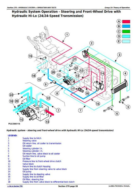
Hydraulic System Components - Steering and Front-Wheel Drive with Hydraulic Hi-Lo (24/24-Speed Transmission)
Hydraulic System Components - Steering and Front-Wheel Drive (24/12-Speed Transmission)
Rockshaft Control Lever Linkage Components
SCVs with Lever and Flow Divider
Group 10: Theory of Operation
Summary of References - Theory of Operation
General Information
Hydraulic System Operation
Hydraulic Filter Operation
Oil Cooler Operation
PTO Clutch Hydraulic Operation
Brake System Operation
Trailer Brake Valve Operation
Hydraulic System Operation - Steering and Front-Wheel Drive with Mechanical Hi-Lo (24/24-Speed Transmission)
Hydraulic System Operation - Steering and Front-Wheel Drive with Hydraulic Hi-Lo (24/24-Speed Transmission)
Hydraulic System Operation - Steering and Front-Wheel Drive (24/12-Speed Transmission)
Shut-Off System Operation (24/12-Speed Transmission) - Shut-Off Block
Shut-Off System Operation (24/12-Speed Transmission) - Shut-Off Valve
Shut-Off System Operation (24/12-Speed Transmission) - Flow Control Valve
Rockshaft Control Valve Operation - Neutral Position
Rockshaft Control Valve Operation - Raise Position
Rockshaft Control Valve Operation - Lower Position
Rockshaft Draft - Sensing Operation
Electro-Hydraulic Hitch Sensing Operation - Neutral Phase
Electro-Hydraulic Hitch Sensing Operation - Loading Phase
Electro-Hydraulic Hitch Sensing Operation - Discharge Phase
Electro-Hydraulic Hitch Sensing II Operation - Neutral Phase
Electro-Hydraulic Hitch Sensing II Operation - Loading Phase
Electro-Hydraulic Hitch Sensing II Operation - Discharge Phase
Double-Acting Selective Control Valve – Neutral Position
Double-Acting Selective Control Valve – Position 1
Double-Acting Selective Control Valve – Position 2
Double-Acting Selective Control Valve - Float Position
Convertible Selective Control Valve in Double-Acting Mode – Neutral Position
Convertible Selective Control Valve in Double-Acting Mode – Return Position
Convertible Selective Control Valve in Double-Acting Mode – Supply Position
Convertible Selective Control Valve in Single-Acting Mode – Neutral Position
Convertible Selective Control Valve in Single-Acting Mode – Return Position
Convertible Selective Control Valve in Single-Acting Mode – Supply Position
Double-Acting Sleeve Coupler Operation
Flow Divider with Solenoid Valve Operation (Only for Tractors without 2nd Flow Divider)
Flow Divider with Solenoid Valve Operation (Only for Tractors with 2nd Flow Divider)
Flow Divider Operation (2nd Flow Divider)
Group 15: Diagnostics
Summary of References - Diagnosis
Safety Precautions
Diagnostic Information
Hydraulic Oil Warm-Up Procedure
Hydraulic System Major Test
Hydraulic System Diagnosis
Insufficient Pump Delivery
Hydraulic Functions Too Slow
Excessive Pump Pressure
Slow Hydraulic Pump Response
Excessive Pump Noise During Operation
Rockshaft Does Not Lift or Lifts Slowly
Rockshaft Does Not Lower or Lowers Slowly
Neutral Position Unstable, Rockshaft Drops After Engine Shut-Down
SCV Control Lever Does Not Return to Neutral Position
SCV Does Not Return to Neutral Position - SCV With Detent Position
SCV Does Not Remain In Detent Position - SCV With Detent Position
Remote Cylinder Does Not Extend or Retract
Remote Cylinder Settles Under Load
Remote Cylinder Operates Too Fast or Too Slow
Group 20: Tests
Summary of References - Tests
Specifications
Hydraulic System Tests - With SCV
Hydraulic System Tests
Pump Flow Test
SCV Relief Valve Test
SCV Leakage Test
EHS II Leakage Test
Rockshaft Lift Cycle Test
Group 25: Adjustments
Summary of References - Adjustments
Rockshaft Control Lever Friction Adjustment
Rockshaft Sensitivity Adjustment
Rockshaft Position Control Adjustment
Rockshaft Draft Control Adjustment
Rockshaft Safety and Relief Valve Adjustment
Electro-Hydraulic Hitch Sensing Adjustment - Electro-Hydraulic Valve Adjustment
Electro-Hydraulic Hitch Sensing Adjustment - Backstop Limit Switch Adjustment
Electro-Hydraulic Hitch Sensing Adjustment - Rotary Position Sensor Adjustment
Electro-Hydraulic Hitch Sensing Adjustment - Draft Sensor Adjustment
Electro-Hydraulic Hitch Sensing II Adjustment - Draft Sensor Rod Adjustment
SCV Relief Valve Adjustment
Flow Divider Adjustment
Flow Divider Adjustment with 2nd Flow Divider
Group 30: Hydraulic System Schematics
Summary of References - Hydraulic System Schematics
Hydraulic Symbols
8/8 and 12/12-Speed Transmission (30 km/h / 18.5 mph) - Steering System without Front-Wheel Drive
24/24-Speed Transmission (30 km/h / 18.5 mph and 40 km/h / 25 mph) - Steering System and Front-Wheel Drive with Mechanical Hi-Lo
24/24-Speed Transmission (30 km/h / 18.5 mph and 40 km/h / 25 mph) - Steering System and Front-Wheel Drive with Electro-Hydraulic Hi-Lo
24/12-Speed Transmission (40 km/h / 25 mph) - Steering System and Front-Wheel Drive with Electro-Hydraulic Management (EHM)
SCV and Rockshaft with Flow Divider
Section 280: Miscellaneous
Group 10: Operational Checks
Operational Test on Front-Wheel Drive Axle
Checking Positive Front-Wheel Lead on Front-Wheel Drive Axle
Section 290: Air-Conditioning System — Operation and Tests
Group 05: Component Location
General Information
Air Conditioning System Components
Heating System Components
Group 10: Theory of Operation
Summary of References — Theory of Operation
Theory of Operation Information
Principle of Heat Exchange
R134a Refrigerant
Operation of Air Conditioning System - Air-Flow
Air-Conditioning System Operation
Compressor
Condenser
Receiver-Drier
Expansion Valve
Group 15: Diagnostics, Tests and Adjustments
Summary of References — Diagnosis, Tests and Adjustments
Safety Equipment
In an Emergency
Storage of Refrigerant Containers
R134a Refrigerant
Important Note
Special or Essential Tools
Special Tools
Diagnostic Information
Air Conditioning System Diagnosis
Pressure Deviations
Air Conditioning System Trouble-Shooting
Failure Of Mechanical Type
Section 299: Special Tools
Group 05: Special Tools (Dealer-Fabricated)
Summary of References — Dealer-Manufactured Tools
Adapter
Cone Point Adjustment Tools
Draft Control Adjusting Tool
Seal Ring Replacement Kit - Tool 1
Seal Ring Replacement Kit - Tool 2
Group 10: Special Tools and Test Equipment
Summary of References - Special Tools and Test Equipment
D01019AA - Single-Speed Hydraulic Hand Pump Assembly
D01072AA - Bushing, Bearing, and Seal Driver Set
D01210AA - Slide Hammer Puller
FKM10472 - Flow Measurement System
FKM10475 - Adjusting Tool
FKM10470 - Pressure measuring system (stage 1)
FKM10471 - Pressure measuring system (stage 2)
JDE83 - Flywheel Turning Tool
JDG19 - Lifting Eyes
JDG1337 - Clutch Repair Fixture
JDG1375 - Clutch Finger Height Gauge
JT02153 - Clamp-on current probe
JT05791A - Multimeter
JT05800 - Digital Thermometer
KJD10491 - Diagnostic Interface Cable
KJD10492 - Puller Tool
KJD10493 - Pressure Tool
KJD10494 - Tensioning Tool
KJD10178-8B - Square Tube
KJD10178C - Cab Tilting Device
CA715825 - Bearing Driver
CA119034 - Seal Ring Driver
CA715600 - Bearing Cup Driver
![]()