
John Deere Tractors 5085E, 5095E, 5100E Diagnosis & Tests Service Technical Manual (TM128219)
Complete Diagnostics & Tests technical manual with Electrical Wiring Diagrams for John Deere Tractors 5085E, 5095E and 5100E (Worldwide), with workshop information to maintain, diagnose, and service like professional mechanics.
John Deere Tractors 5085E, 5095E & 5100E workshop operation tests manual includes:
* Numbered table of contents easy to use so that you can find the information you need fast.
* Detailed sub-steps expand on repair procedure information
* Numbered instructions guide you through every repair procedure step by step.
* Troubleshooting and electrical service procedures are combined with detailed wiring diagrams for ease of use.
* Notes, cautions and warnings throughout each chapter pinpoint critical information.
* Bold figure number help you quickly match illustrations with instructions.
* Detailed illustrations, drawings and photos guide you through every procedure.
* Enlarged inset helps you identify and examine parts in detail.
tm128219 - 5085E and 5100E (IT4) Tractors Diagnostic Technical Manual.pdf
tm128219 - 5085E and 5100E (IT4) Tractors Diagnostic Technical Manual.epub
Total Pages: 2,887pages
File Format: PDF (bookmarked, ToC, Searchable, Printable, high quality) & EPUB/MOBI/AZW for Kindle/iPad/iPhone/Android.
Language: English
MAIN SECTIONS
Foreword
General Information
Safety
General References
Technical Specific References
Diagnostic Trouble Codes
CCU Code Diagnostics
ECU Code Diagnostics
EIC Code Diagnostics
ICC Code Diagnostics
PTR Code Diagnostics
Observable Symptoms and System Diagnostics
General References
Engine Diagnostics
Fuel, Air Intake, Exhaust, and Cooling Diagnostics
Electrical Diagnostics
Electronic Control Unit Diagnostics
Drive Systems and Transmission Diagnostics
Steering and Brakes Diagnostics
Hydraulic Diagnostics
Cab/Open Operator's Station Diagnostics
Engine
General References
Engine Calibrations, Preliminary Checks and Operational Checks
Engine Theory of Operation
Engine Schematics
Engine Component and Connector Information
Engine Tests and Adjustments
Fuel, Air Intake, Exhaust, and Cooling
General References
Fuel, Air Intake, Exhaust, and Cooling Calibrations, Preliminary and Operational Checks
Fuel, Air Intake, Exhaust, and Cooling Theory of Operation
Fuel, Air Intake, Exhaust, and Cooling Schematics
Fuel, Air Intake, Exhaust, and Cooling Component and Connector Information
Fuel, Air Intake, Exhaust, and Cooling Tests and Adjustments
Electrical General and Theory of Operation
General References
Turn Signal Switch and Warning Lights
Warning and Turn Signal Lighting (License and Clearance Lights)
Wipers (Two Speed)
Wipers (Single Speed)
Rear Wipers
Instrument Cluster Control (ICC)
Electrohydraulic Control Unit (EHC)
Power Train Reverser (PTR)
Chassis Control Unit (CCU)
Engine Control Unit (ECU)
Controller Area Network
Electrical Schematics
General References
Key Switch, Starter and Alternator (SE1)
Neutral Start (SE2)
Accessory Power (SE3)
Horn (SE4)
Light Switch, Headlights, and Signal Lights (SE5A)
Cab Work Lighting (SE5B)
Open Operator Station Work Lighting (SE5C)
Turn Signal Switch and Warning Lights (SE6)
Light Switch, Headlights and Signal Lights (License and Clearance Lights) (SE7A)
Cab Work Lighting (License and Clearance Lights) (SE7B)
Warning and Turn Signal Lighting (License and Clearance Lights) (SE8)
Junction Block Power (SE9)
Trailer Connector (SE10)
Trailer Connector (Implement Flood Light Connector) (SE11)
Loader Lights (SE12)
Back-Up Alarm (SE13A)
Beacon Light (SE13B)
Mid-Mount SCV (SE14)
Power Outlets (Square Terminals) (SE15A)
Power Outlets (Round Terminals) (SE15B)
Heating (SE16)
Air Conditioning (SE17)
Wipers (Two Speed) (SE19)
Wipers (Single Speed) (SE20)
Rear Wipers (SE21)
Dome Light, Door Switch, and Radio (SE22)
Air Seat (SE23)
Instrument Cluster Control (ICC) (SE24)
Seat, Rear PTO and Wheel Speed (SE25A)
Multi-Function Control Lever (SE25B)
ELX Relay and Fuses (SE26)
Mechanical Front-Wheel Drive (MFWD) (SE27)
Brake Switch (SE28)
Electrohydraulic Control Unit (EHC) (SE29A)
Power Train Reverser Control Unit (PTR) (SE29B)
Chassis Control Unit (CCU) (SE29C)
Engine Control Unit (ECU) (SE30)
Controller Area Network (SE32)
Electrical Components and Connectors
General References
Starting and Charging (SE1)
Neutral Start (SE2)
Accessory Power (SE3)
Horn (SE4)
Light Switch, Headlights, and Signal Lights (SE5A)
Cab Work Lighting (SE5B)
Open Operator Station Work Lighting (SE5C)
Turn Signal Switch and Warning Lights (SE6)
Light Switch, Headlights and Signal Lights (License and Clearance Lights) (SE7A)
Cab Work Lighting (License and Clearance Lights) (SE7B)
Warning Light Switch and Turn Signal Lighting (License and Clearance Lights) (SE8)
Junction Block Power (SE9)
Trailer Connector (SE10)
Trailer Connector (Implement Flood Light Connector) (SE11)
Loader Lights (SE12)
Back-Up Alarm (SE13A)
Beacon Light (SE13B)
Mid-Mount SCV (SE14)
Power Outlets (Square Terminals) (SE15A)
Power Outlets (Round Terminals) (SE15B)
Heating (SE16)
Air Conditioning (SE17)
Wipers (Two Speed) (SE19)
Wipers (Single Speed) (SE20)
Rear Wipers (SE21)
Dome Light, Door Switch and Radio (SE22)
Air Seat (SE23)
Instrument Cluster Control (ICC) (SE24)
Seat, Rear PTO and Wheel Speed (SE25A)
Multi-Function Control Lever (SE25B)
ELX Relay and Fuses (SE26)
Mechanical Front-Wheel Drive (MFWD) (SE27)
Brake Switch (SE28)
Electrohydraulic Control Unit (EHC) (SE29A)
Power Train Reverser (PTR) (SE29B)
Chassis Control Unit (CCU) (SE29C)
Engine Control Unit (ECU) (SE30)
Controller Area Network (SE32)
Fuses and Relays
Ground Points
Interconnects
Wiring Harnesses
Electrical Tests and Adjustments
General References
Starting and Charging
Neutral Start
Accessory Power
Horn
Light Switch, Headlights, and Signal Lights
Cab Work Lighting
Open Operator Station Work Lighting
Turn Signal Switch and Warning Lights
Light Switch, Headlights and Signal Lights (License and Clearance Lights)
Cab Work Lighting (License and Clearance Lights)
Warning and Turn Signal Lighting (License and Clearance Lights)
Junction Block Power
Trailer Connector
Trailer Connector (Implement Flood Light Connector)
Loader Lights
Back-Up Alarm
Beacon Light
Mid-Mount SCV
Power Outlets (Square Terminals)
Power Outlets (Round Terminals)
Heating
Air Conditioning
Wipers (Two Speed)
Wipers (Single Speed)
Rear Wipers
Dome Light, Door Switch and Radio
Air Seat
Instrument Cluster Control (ICC)
Seat, Rear PTO and Wheel Speed
Multi-Function Control Lever
ELX Relay and Fuses
Mechanical Front-Wheel Drive (MFWD)
Brake Switch
Electrohydraulic Control Unit (EHC)
Power Train Reverser (PTR)
Chassis Control Unit (CCU)
Engine Control Unit (ECU)
Controller Area Network
Electronic Control Units
General References
Calibrations, Preliminary Checks and Operational Checks
Theory of Operation
Schematics
Component and Connector Information
Tests and Adjustments
Chassis Control Unit (CCU)
Engine Control Unit (ECU)
Engine Interface Control Unit (EIC)
Instrument Cluster Control Unit (ICC)
Power Train Reverser (PTR)
Drive Systems and Transmissions
General References
Calibrations, Preliminary Checks and Operational Checks
Drive Systems and Transmission Theory of Operation
Drive Systems and Transmission Schematics
Drive Systems and Transmission Component and Connector Information
Drive Systems Tests and Adjustments
Transmission Tests and Adjustments
Steering and Brakes
General References
Brake Calibrations, Preliminary Checks and Operational Checks
Steering Calibrations, Preliminary Checks and Operational Checks
Brake Theory of Operation
Secondary Brake Theory of Operation
Steering Theory of Operation
Brake Schematics
Steering Schematics
Brake Component and Connector Information
Secondary Brake Component and Connector Information
Steering Component and Connector Information
Brake Tests and Adjustments
Secondary Brake Tests and Adjustments
Steering Tests and Adjustments
Hydraulics
General References
Calibrations, Preliminary Checks and Operational Checks
General Hydraulics Theory of Operation
Mechanical Hitch Theory of Operation
Hydraulic Filter Theory of Operation
Hydraulic Pump Theory of Operation
Dual Mid-Mount SCV Theory of Operation
Power Beyond Theory of Operation
Quick Disconnect Coupler Theory of Operation
Dual Rear SCV Theory of Operation
Triple Mid-Mount SCV Theory of Operation
Triple Rear SCV Theory of Operation
Hydraulic Trailer Brake Theory of Operation
Schematics
Component and Connector Information
Tests and Adjustments
Cab/Open Operator's Station
General References
Calibrations, Preliminary Checks and Operational Checks
HVAC Theory of Operation
Seat Theory of Operation
Schematics
Component and Connector Information
Tests and Adjustments
Special Tools
General References
Dealer Fabricated and Service Tools
tm128219 - 5085E and 5100E (IT4) Tractors Diagnostic Technical Manual
Table of Contents
Foreword
Section 210: General Information
Group 05A: Safety
Work In Ventilated Area
Recognize Safety Information
Avoid Backover Accidents
Prevent Machine Runaway
Avoid Contact with Agricultural Chemicals
Clean Vehicle of Hazardous Pesticides
Use a Safety Chain
Work in Clean Area
Decommissioning: Proper Recycling and Disposal of Fluids and Components
Avoid Harmful Asbestos Dust
Avoid Hot Exhaust
Clean Exhaust Filter Safely
Handle Fuel Safely—Avoid Fires
Prepare for Emergencies
Handle Fluids Safely—Avoid Fires
Avoid High-Pressure Fluids
Install All Guards
Use Proper Lifting Equipment
Illuminate Work Area Safely
Live With Safety
Service Machines Safely
Support Machine Properly
Remove Paint Before Welding or Heating
Park Machine Safely
Stay Clear of Rotating Drivelines
Follow Safety Instructions
Use Proper Tools
Service Tires Safely
Keep ROPS Installed Properly
Construct Dealer-Made Tools Safely
Practice Safe Maintenance
Understand Signal Words
Replace Safety Signs
Avoid Heating Near Pressurized Fluid Lines
Wear Protective Clothing
Service Accumulator Systems Safely
Handling Batteries Safely
Handle Agricultural Chemicals Safely
Service Cooling System Safely
Use Steps and Handholds Correctly
Transport Tractor Safely
Group 05B: General References
General Information - Summary of References
Regions and Country Versions
Deliver Safely
Glossary of Terms
Information Available in Sections, Groups and Subgroups
Trademarks
Group 05C: Technical Specific References
Features and Accessories
Metric Bolt and Screw Torque Values
Unified Inch Bolt and Screw Torque Values
Section 211: Diagnostic Trouble Codes
Group CCU: CCU Code Diagnostics
CCU 000096.03 - Fuel Level Sensor Circuit Voltage High
CCU 000096.04 - Fuel Level Sensor Circuit Voltage Low
CCU 000237.02 - VIN Security Data Conflict
CCU 000237.31 - VIN Security Messages Missing
CCU 000628.02 - CCU EOL Data Fault
CCU 000630.14 - Rear PTO Configuration Invalid
CCU 001638.00 - Hydraulic Oil Temperature Very Hot
CCU 001638.03 - Hydraulic Oil Temperature Sensor Circuit Voltage High
CCU 001638.04 - Hydraulic Oil Temperature Sensor Circuit Voltage Low
CCU 001638.16 - Hydraulic Oil Temperature High
CCU 001883.00 - Rear PTO Overspeed
CCU 001883.01 - Rear PTO Underspeed
CCU 002818.31 - Operator Presence Switch Not Activated
CCU 003509.03 - Sensor Supply Voltage Out of Range High
CCU 003509.04 - Sensor Supply Voltage Out of Range Low
CCU 523316.04 - CCU Switched Supply Voltage Low
CCU 523839.02 - Secondary Brake Switch Conflict
CCU 524037.02 - MFWD Switch Circuit Fault
CCU 524235.05 - MFWD Solenoid Circuit Fault
CCU 524252.05 - Rear PTO Solenoid Circuit Fault
Group ECU: ECU Code Diagnostics
ECU - Non-Tractor ECU Codes
ECU 000084.31 - ECU Calculated Vehicle Speed and CAN bus Vehicle Speed Mismatch
ECU 000152.12 - Control Unit Fault
ECU 000152.14 - Control Unit Fault
ECU 000152.16 - Control Unit Fault
ECU 000237.02 - VIN Security Data Invalid
ECU 000237.13 - VIN Option Code Security Data Conflict
ECU 000237.31 - VIN Security Data Missing
ECU 000647.03 - Engine Fan Clutch Output Device Driver Voltage Above Normal, Or Shorted To High Source
ECU 000695.19 - Unapproved Engine Speed Request
ECU 000876.05 - Air Conditioner Compressor Clutch Circuit Open
ECU 000876.06 - Air Conditioner Compressor Clutch Circuit Short To Ground
ECU 001069.31 - Tire Size Error
ECU 001110.31 - Engine Protection Shutdown
ECU 001351.05 - Air Brake Compressor Clutch open circuit
ECU 001351.06 - Air Brake Compressor Clutch Short To Ground
ECU 001550.05 - Air Conditioner Compressor Clutch Under-Current
ECU 001550.06 - Air Conditioner Compressor Clutch Over-Current
ECU 003353.31 - Alternator Not Charging With Engine Running
ECU 003695.03 - Diesel Particulate Filter Regeneration Inhibit Switch Shorted To Battery
ECU 003695.04 - Diesel Particulate Filter Regeneration Inhibit Switch Shorted To Ground
ECU 003695.05 - Diesel Particulate Filter Regeneration Inhibit Switch Circuit Open
ECU 003695.13 - Diesel Particulate Filter Regeneration Inhibit Switch Out Of Calibration
ECU 003695.14 - Diesel Particulate Filter Regeneration Special Instructions
ECU 003696.03 - Diesel Particulate Filter Regeneration Force Switch Shorted To Battery
ECU 003696.04 - Diesel Particulate Filter Regeneration Force Switch Shorted To Ground
ECU 003696.05 - Diesel Particulate Filter Regeneration Force Switch Current Low
ECU 003711.14 - Exhaust Temperature Management Failure Special Instructions
ECU 003711.31 - DOC Inlet Temperature Not Reached During ETM
ECU 524225.31 - Engine Start Protection Bypass Detected
Group EIC: EIC Code Diagnostics
EIC 000628.02 - EIC EOL Data Fault
EIC 000628.12 - EIC Programming Fault
EIC 000630.13 - EIC Calibration Fault/Not Calibrated
EIC 001237.31 - Failed Key Authentication
EIC 002000.09 - ECU Message Missing
EIC 003695.14 - Diesel Particulate Filter Regeneration Fault
EIC 003719.15 - Diesel Particulate Filter Regeneration Fault
EIC 521214.11 - Immobilizer Control Device Fault
EIC 521321.12 - Immobilizer Control Device Fault
EIC 521322.31 - Immobilizer Control Device Fault
EIC 523702.14 - EIC Control Unit Fault
EIC 523702.31 - EIC Control Unit Fault
Group ICC: ICC Code Diagnostics
ICC 000107.00 - Air Filter Restricted
ICC 000167.04 - Alternator Voltage Below Normal
ICC 000237.02 - ICC VIN Security Mismatch
ICC 000237.31 - ICC VIN Security Missing
ICC 000628.12 - ICC Programming Fault
ICC 000630.02 - ICC Calibration Memory Fault
ICC 002818.31 - Operator Presence Switch Not Activated
Group PTR: PTR Code Diagnostics
PTR 000084.07 - Excessive Wheel Speed Detected During Calibration
PTR 000158.01 - System Switched Voltage Low
PTR 000162.02 - High/Low Switch Circuit Conflict
PTR 000162.31 - High, Low Switch Stuck On
PTR 000190.18 - Engine Speed Missing During Shift
PTR 000191.00 - Excessive Top Shaft Speed During Calibration
PTR 000191.17 - Top Shaft Speed Too Low
PTR 000598.02 - Clutch Switch Open With Pedal Up
PTR 000598.04 - Clutch Switch Signal Failed Low
PTR 000628.02 - EOL Data Fault
PTR 000630.14 - Tractor Model Out Of Range/Transmission Calibration Value High
PTR 000752.03 - Power Shuttle Potentiometer Input Voltage High
PTR 000752.04 - Power Shuttle Potentiometer Input Voltage Low
PTR 001504.10 - Seat Switch Closed Too Long
PTR 002820.31 - Operator Not Present During Shift
PTR 002825.07 - Not Valid Neutral Park Command
PTR 003509.03 - PTR Sensor Supply Voltage High
PTR 003509.04 - PTR Sensor Supply Voltage Low
PTR 521233.05 - High Valve Driver Fault
PTR 521234.05 - Low Valve Driver Fault
PTR 521235.05 - Reverse Valve Driver Fault
PTR 522456.07 - Speed Control Lever Park and Neutral Switch Conflict
PTR 522456.31 - Speed Control Lever Transition Without Using Clutch Pedal
PTR 523953.02 - Speed Control Lever Sensor Circuit Conflict
PTR 523959.31 - No Wheel Speed While in Gear
PTR 523966.31 - Come Home Detected
PTR 524020.31 - Reverser in Gear at Power-Up
PTR 524021.31 - Directional Reverser Lever Switch Circuit Fault
PTR 524160.02 - Not Valid Neutral/Not Neutral Switch
PTR 524173.02 - Clutch Pedal Compare Error
PTR 524173.14 - Sync Lever Shift Without Clutch Pedal Engaged
PTR 524173.15 - Clutch Pedal Voltage High
PTR 524173.16 - Both Clutch Pedals Voltage High
PTR 524173.17 - Clutch Pedal Voltage Low
PTR 524173.18 - Both Clutch Pedals Voltage Low
PTR 524230.05 - Enable Valve Driver Fault
PTR 524230.07 - Enable Valve Stuck
PTR 524234.03 - Pressure Sensor Voltage High
PTR 524234.04 - Pressure Sensor Voltage Low
PTR 524254.03 - Transmission Enable Valve Power High
PTR 524254.04 - Transmission Enable Valve Power Low
PTR 524267.15 - High Speed Shuttle Shift
Section 212: Observable Symptoms and System Diagnostics
Group 05B: General References
Observable Symptoms and System Diagnostics - Summary of References
Group 20: Engine Diagnostics
Engine System Problems
Group 30: Fuel, Air Intake, Exhaust, and Cooling Diagnostics
Fuel and Air System Problems
Group 40: Electrical Diagnostics
Back-Up Alarm Problems
Charging System Problems
Door Switch and Dome Light Problems
Electrical Connector Problems
Horn Problems
Lighting System Problems
Power Outlet Problems
Starting System Problems
Trailer Connector and Junction Block Problems
Group 45: Electronic Control Unit Diagnostics
CAN System Diagnosis
Chassis Control Unit (CCU) Problems
Codes After Adding / Removing Control Units
Control Unit Problems
Control Unit Programming Failed
Control Unit System Diagnosis
Engine Control Unit (ECU) Problems
Instrument Cluster Control (ICC) Problems
Power Train Reverser (PTR) Problems
Programming Multiple Control Units
Group 50: Drive Systems and Transmission Diagnostics
MFWD Problems
MFWD System Diagnosis
PowrReverser Transmission Problems
PowrReverser Transmission System Diagnosis
Rear PTO Problems
Rear PTO System Diagnosis
Group 60: Steering and Brakes Diagnostics
Brake Problems
Brake System Diagnosis
Steering Problems
Steering System Diagnosis
Group 70: Hydraulic Diagnostics
Mechanical Hitch Problems
Mechanical Hitch System Diagnosis
Mid-Mount SCV Problems
Mid-Mount SCV System Diagnosis
Rear SCV Problems
Rear SCV System Diagnosis
Hydraulic Trailer Brake Problems
Hydraulic Trailer Brake System Diagnosis
Group 90: Cab/Open Operator's Station Diagnostics
HVAC Problems
HVAC System Diagnosis
Radio Problems
Seat Problems
Wiper Problems
Section 220: Engine
Group 05B: General References
Engine - Summary of References
Engine Information
Group 10AA: Engine Calibrations, Preliminary Checks and Operational Checks
Engine Calibrations, Preliminary Checks and Operational Checks
Group 20AA: Engine Theory of Operation
Engine Theory of Operation
Group 30AA: Engine Schematics
Engine Schematics
Group 40AA: Engine Component and Connector Information
Engine Components
Group 50AA: Engine Tests and Adjustments
Engine Test Procedures and Adjustments
Engine Performance Testing
Engine Performance Variables
Section 230: Fuel, Air Intake, Exhaust, and Cooling
Group 05B: General References
Fuel, Air Intake, Exhaust, and Cooling - Summary of References
Fuel, Air Intake, Exhaust, and Cooling Information
Group 10AA: Fuel, Air Intake, Exhaust, and Cooling Calibrations, Preliminary and Operational Checks
Fuel and Air System Calibrations, Preliminary and Operational Checks
Group 20AA: Fuel, Air Intake, Exhaust, and Cooling Theory of Operation
Air Intake System Theory of Operation
Cooling System Theory of Operation
Exhaust System Theory of Operation
Fuel System Theory of Operation
Group 30AA: Fuel, Air Intake, Exhaust, and Cooling Schematics
Fuel, Air Intake, Exhaust, and Cooling Schematics
Group 40AA: Fuel, Air Intake, Exhaust, and Cooling Component and Connector Information
Fuel, Air Intake, Exhaust, and Cooling Component and Connector Information
Group 50AA: Fuel, Air Intake, Exhaust, and Cooling Tests and Adjustments
Fuel, Air Intake, Exhaust, and Cooling Tests and Adjustments
Section 240A: Electrical General and Theory of Operation
Group 05B: General References
Electrical General and Theory of Operation - Summary of References
Circuit Malfunctions
Circuit Types
Electrical Designators
Electrical Procedure
Electrical Schematic Symbols
Reading Wiring Schematics and Diagrams
Relay Circuit Types
Troubleshooting Unresolved Electrical/Electronic Problems
Using a Digital Multimeter
Using a Probe Light
Visually Inspect Electrical System
Wiring Diagram and Schematic Information
Group 20DD: Turn Signal Switch and Warning Lights
Turn Signal Switch and Warning Lights Theory of Operation
Group 20ED: Warning and Turn Signal Lighting (License and Clearance Lights)
Warning and Turn Signal Lighting Theory of Operation (with License and Clearance Lights)
Group 20MA: Wipers (Two Speed)
Front Wiper Switch (Two Speed) Theory of Operation
Group 20MB: Wipers (Single Speed)
Front Wiper Switch (Single Speed) Theory of Operation
Group 20MC: Rear Wipers
Rear Wiper Switch Theory of Operation
Group 20PA: Instrument Cluster Control (ICC)
Instrument Cluster Control (ICC) Theory of Operation
Instrument Cluster Alarm Theory of Operation
Group 20UA: Electrohydraulic Control Unit (EHC)
Electrohydraulic Control Unit (EHC) Theory of Operation
Group 20UC: Power Train Reverser (PTR)
Power Train Reverser (PTR) Theory of Operation
Group 20UD: Chassis Control Unit (CCU)
Chassis Control Unit (CCU) Theory of Operation (PR Transmission)
Fuel Level Sensor Theory of Operation (PR Transmission)
Group 20VA: Engine Control Unit (ECU)
Engine Control Unit (ECU) Theory of Operation
Group 20WA: Controller Area Network
CAN Communication System Theory Of Operation
Section 240B: Electrical Schematics
Group 05B: General References
Electrical Schematics - Summary of References
Group 30AA: Key Switch, Starter and Alternator (SE1)
Key Switch, Starter and Alternator Schematic and Circuit Diagram (SE1)
Group 30AC: Neutral Start (SE2)
Neutral Start Schematic and Circuit Diagram (SE2)
Group 30BA: Accessory Power (SE3)
Accessory Power Schematic and Circuit Diagram (SE3)
Group 30CA: Horn (SE4)
Horn Schematic and Circuit Diagram (SE4)
Group 30DA: Light Switch, Headlights, and Signal Lights (SE5A)
Light Switch, Headlights, and Signal Lights Schematic and Circuit Diagram (SE5A)
Group 30DB: Cab Work Lighting (SE5B)
Cab Work Lighting Schematic and Circuit Diagram (SE5B)
Group 30DC: Open Operator Station Work Lighting (SE5C)
Open Operator Station Work Lighting Schematic and Circuit Diagram (SE5C)
Group 30DD: Turn Signal Switch and Warning Lights (SE6)
Turn Signal Switch and Warning Lights Schematic and Circuit Diagram (SE6)
Group 30EA: Light Switch, Headlights and Signal Lights (License and Clearance Lights) (SE7A)
Light Switch, Headlights and Signal Lights Schematic and Circuit Diagram (with License and Clearance Lights) (SE7A)
Group 30EB: Cab Work Lighting (License and Clearance Lights) (SE7B)
Cab Work Lighting Schematic and Circuit Diagram (with License and Clearance Lights) (SE7B)
Group 30ED: Warning and Turn Signal Lighting (License and Clearance Lights) (SE8)
Warning and Turn Signal Lighting Schematic and Circuit Diagram (with License and Clearance Lights) (SE8)
Group 30FA: Junction Block Power (SE9)
Junction Block Power Schematic and Circuit Diagram (SE9)
Group 30GA: Trailer Connector (SE10)
Trailer Connector Schematic and Circuit Diagram (SE10)
Group 30GB: Trailer Connector (Implement Flood Light Connector) (SE11)
Trailer Connector Schematic and Circuit Diagram (with Implement Flood Light Connector) (SE11)
Group 30HA: Loader Lights (SE12)
Loader Lights Schematic and Circuit Diagram (SE12)
Group 30IA: Back-Up Alarm (SE13A)
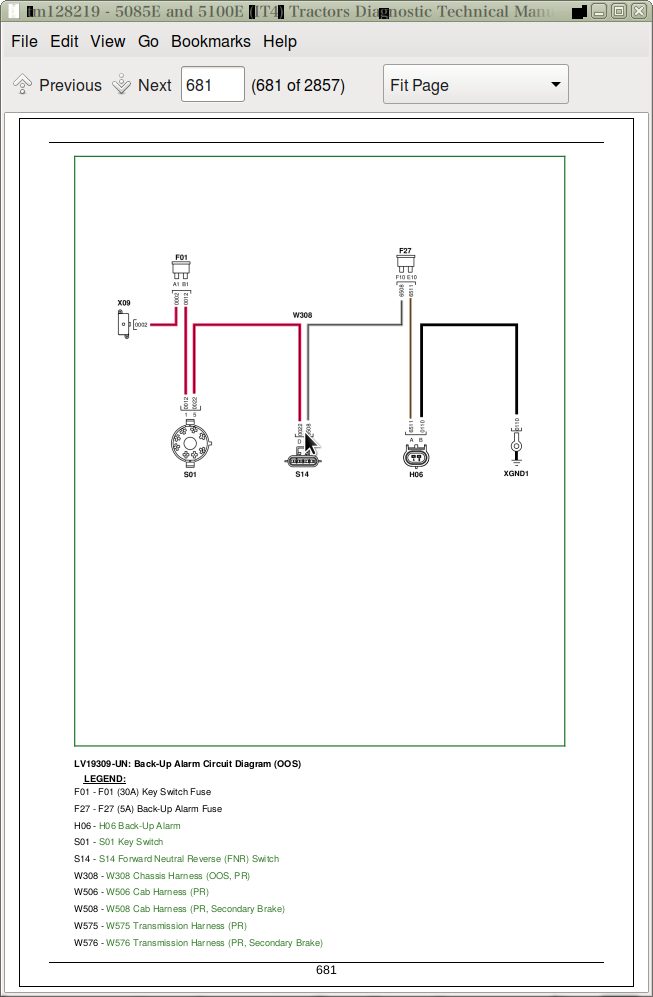
Back-Up Alarm Schematic and Circuit Diagram (SE13A)
Group 30IB: Beacon Light (SE13B)
Beacon Light Schematic and Circuit Diagram (SE13B)
Group 30JA: Mid-Mount SCV (SE14)
Mid-Mount SCV Schematic and Circuit Diagram (SE14)
Group 30KA: Power Outlets (Square Terminals) (SE15A)
Power Outlets Schematic and Circuit Diagram (with Square Terminals) (SE15A)
Group 30KB: Power Outlets (Round Terminals) (SE15B)
Power Outlets Schematic and Circuit Diagram (with Round Terminals) (SE15B)
Group 30LA: Heating (SE16)
Heating Schematic and Circuit Diagram (SE16)
Group 30LB: Air Conditioning (SE17)
Air Conditioning Schematic and Circuit Diagram (SE17)
Group 30MA: Wipers (Two Speed) (SE19)
Wipers Schematic and Circuit Diagram (Two Speed) (SE19)
Group 30MB: Wipers (Single Speed) (SE20)
Wipers Schematic and Circuit Diagram (Single Speed) (SE20)
Group 30MC: Rear Wipers (SE21)
Rear Wipers Schematic and Circuit Diagram (SE21)
Group 30NA: Dome Light, Door Switch, and Radio (SE22)
Dome Light, Door Switch, and Radio Schematic and Circuit Diagram (SE22)
Group 30OA: Air Seat (SE23)
Air Seat Schematic and Circuit Diagram (SE23)
Group 30PA: Instrument Cluster Control (ICC) (SE24)
Instrument Cluster Control (ICC) Schematic and Circuit Diagram (SE24)
Group 30QA: Seat, Rear PTO and Wheel Speed (SE25A)
Seat Switch, Rear PTO Switch and Wheel Speed Sensor Schematic and Circuit Diagram (SE25A)
Group 30QB: Multi-Function Control Lever (SE25B)
Multi-Function Control Lever Schematic and Circuit Diagram (SE25B)
Group 30RA: ELX Relay and Fuses (SE26)
ELX Relay and Fuses Schematic and Circuit Diagram (SE26)
Group 30SA: Mechanical Front-Wheel Drive (MFWD) (SE27)
Mechanical Front-Wheel Drive (MFWD) Schematic and Circuit Diagram (SE27)
Group 30TA: Brake Switch (SE28)
Brake Switch Schematic and Circuit Diagram (SE28)
Group 30UA: Electrohydraulic Control Unit (EHC) (SE29A)
Electrohydraulic Control Unit (EHC) Schematic and Circuit Diagram (SE29A)
Group 30UC: Power Train Reverser Control Unit (PTR) (SE29B)
Power Train Reverser Control Unit (PTR) Schematic and Circuit Diagram (SE29B)
Group 30UD: Chassis Control Unit (CCU) (SE29C)
Chassis Control Unit (CCU) Schematic and Circuit Diagram (PR Transmission) (SE29C)
Group 30VA: Engine Control Unit (ECU) (SE30)
Engine Control Unit (ECU) Schematic and Circuit Diagram (SE30)
Group 30WA: Controller Area Network (SE32)
Controller Area Network Schematic and Circuit Diagram (SE32)
Section 240C: Electrical Components and Connectors
Group 05B: General References
Electrical Components and Connectors - Summary of References
Group 40AA: Starting and Charging (SE1)
F26 (125A) Fusible Link
G01 Battery
G02 Alternator
M01 Starter Motor/Solenoid
S01 Key Switch
Group 40AC: Neutral Start (SE2)
K11 Neutral Relay
K18 Neutral Start Relay
Group 40BA: Accessory Power (SE3)
K07 Accessory Relay
Group 40CA: Horn (SE4)
H01 Horn
S05 Horn Switch
Group 40DA: Light Switch, Headlights, and Signal Lights (SE5A)
E01 Right Front High/Low Beam Headlight
E02 Left Front High/Low Beam Headlight
H02 Right Tail/Turn Light
H03 Left Tail/Turn Light
H08 Left Brake Light
H09 Right Brake Light
H14 Right Rear Tail/Turn/Warning Light
H15 Left Rear Tail/Turn/Warning Light
K27 Headlight Relay
S06 Light Switch
S45 HI/LO Headlight Switch
V01 Diode Block
Group 40DB: Cab Work Lighting (SE5B)
E03 Left Front Work Light
E04 Right Front Work Light
E05 Left Rear Work Light
E06 Right Rear Work Light
E07 Left Front Work Light
E08 Right Front Work Light
E09 Right Rear Work Light
E10 Left Rear Work Light
Group 40DC: Open Operator Station Work Lighting (SE5C)
E11 Left Rear Work Light
E12 Right Rear Work Light
E13 Right Front Work Light
E14 Left Front Work Light
Group 40DD: Turn Signal Switch and Warning Lights (SE6)
H04 Right Front Warning Light
H05 Left Front Warning Light
H10 Right Rear Warning Light
H11 Left Rear Warning Light
S43 Turn Signal Switch
Group 40EA: Light Switch, Headlights and Signal Lights (License and Clearance Lights) (SE7A)
E01 Right Front High/Low Beam Headlight (with License and Clearance Lights)
E02 Left Front High/Low Beam Headlight (with License and Clearance Lights)
E19 Left License Plate Light (with License and Clearance Lights)
E20 Right License Plate Light (with License and Clearance Lights)
H02 Right Tail/Turn Light (with License and Clearance Lights)
H03 Left Tail/Turn Light (with License and Clearance Lights)
H16 Right Front Clearance/Turn/Warning Light (with License and Clearance Lights)
H17 Left Front Clearance/Turn/Warning Light (with License and Clearance Lights)
H23 Right Front Clearance/Turn/Warning Light (with License and Clearance Lights)
H24 Left Front Clearance/Turn/Warning Light (with License and Clearance Lights)
K27 Headlight Relay (with License and Clearance Lights)
S06 Light Switch (with License and Clearance Lights)
S45 HI/LO Headlight Switch (with License and Clearance Lights)
V01 Diode Block (with License and Clearance Lights)
Group 40EB: Cab Work Lighting (License and Clearance Lights) (SE7B)
E31 Left Rear Work Light (with License and Clearance Lights)
E32 Right Rear Work Light (with License and Clearance Lights)
E33 Left Front Work Light (with License and Clearance Lights)
E34 Right Front Work Light (with License and Clearance Lights)
E35 Left Rear Work Light (with License and Clearance Lights)
E36 Right Rear Work Light (with License and Clearance Lights)
E37 Left Front Work Light (with License and Clearance Lights)
E38 Right Front Work Light (with License and Clearance Lights)
S22 Front Work Light Switch (with License and Clearance Lights)
S24 Rear Work Light Switch (with License and Clearance Lights)
Group 40ED: Warning Light Switch and Turn Signal Lighting (License and Clearance Lights) (SE8)
K30 Flasher Logic Relay (with License and Clearance Lights)
S10 Warning Light Switch (with License and Clearance Lights)
S43 Turn Signal Switch (with License and Clearance Lights)
Group 40FA: Junction Block Power (SE9)
X02 Junction Block
Group 40GA: Trailer Connector (SE10)
X01 Trailer Connector
Group 40GB: Trailer Connector (Implement Flood Light Connector) (SE11)
X01_1 Trailer Connector (with Implement Flood Light Connector)
X01_2 Implement Flood Light Connector
Group 40HA: Loader Lights (SE12)
E15 Left Front Loader Light
E16 Right Front Loader Light
E21 Right Front High/Low Beam/Clearance Light (with License and Clearance Lights)
E22 Left Front High/Low Beam/Clearance Light (with License and Clearance Lights)
S26 Loader Light Switch
Group 40IA: Back-Up Alarm (SE13A)
H06 Back-Up Alarm
Group 40IB: Beacon Light (SE13B)
H07 Beacon Light
S25 Beacon Light Switch
Group 40JA: Mid-Mount SCV (SE14)
K25 Mid-Mount SCV Retract (Black) 3rd Function Relay
K26 Mid-Mount SCV Extend (Gray) 3rd Function Relay
S19 Mid-Mount SCV 3rd Function Switch
Y03 Mid-Mount SCV Retract (Black) 3rd Function Solenoid Valve
Y04 Mid-Mount SCV Extend (Gray) 3rd Function Solenoid Valve
Group 40KA: Power Outlets (Square Terminals) (SE15A)
X03 Convenience Outlet (Convenience Outlet with Square Terminals)
X05 Auxiliary Power Strip (Convenience Outlet with Square Terminals)
X06 Power Outlet (Convenience Outlet with Square Terminals)
Group 40KB: Power Outlets (Round Terminals) (SE15B)
X04 Convenience Outlet (Convenience Outlet with Round Terminals)
X05 Auxiliary Power Strip (Convenience Outlet with Round Terminals)
X06 Power Outlet (Convenience Outlet with Round Terminals)
Group 40LA: Heating (SE16)
M02 Left HVAC Blower Motor
M03 Right HVAC Blower Motor
R03 HVAC Resistor
S08 HVAC Blower Switch
Group 40LB: Air Conditioning (SE17)
B07 A/C Deicing Switch
B08 A/C High/Low Pressure Switch
M04 A/C Compressor Clutch
S09 A/C ON/OFF Switch
Group 40MA: Wipers (Two Speed) (SE19)
M05 Front Wiper Motor (Two Speed)
M06 Front Washer Pump (Two Speed)
S30 Front Wiper Switch (Two Speed)
Group 40MB: Wipers (Single Speed) (SE20)
M05_1 Front Wiper Motor (Single Speed)
M06 Front Washer Pump (Single Speed)
S30_1 Front Wiper Switch (Single Speed)
Group 40MC: Rear Wipers (SE21)
M07 Rear Wiper Motor
M08 Rear Washer Pump
S11 Rear Wiper Switch
Group 40NA: Dome Light, Door Switch and Radio (SE22)
A03 Dome Light and Switch Assembly
B240 Right Speaker
B241 Left Speaker
E18 Right-Hand Console Light
S13 Left Door Switch
X08 Radio Connector
Group 40OA: Air Seat (SE23)
A05 Air Seat Assembly
Group 40PA: Instrument Cluster Control (ICC) (SE24)
A01 Instrument Cluster Control (ICC)
A01X1 Instrument Control Cluster (ICC) Connector
A01X2 Instrument Control Cluster (ICC) Connector
A01X3 Instrument Control Cluster (ICC) Connector
A01X4 Instrument Control Cluster (ICC) Connector
H18 Instrument Cluster Alarm
S36 Roll Mode Switch
Group 40QA: Seat, Rear PTO and Wheel Speed (SE25A)
B10 Wheel Speed Sensor
S02 Rear PTO ON/OFF Switch
S04 Seat Switch
Group 40QB: Multi-Function Control Lever (SE25B)
A11 Multi-Function Control Lever Controller
S48 Multi-Function Control Lever Switch
Y26 Multi-Coupler
Group 40RA: ELX Relay and Fuses (SE26)
ELX Relay and Fuses Component and Connectors
Group 40SA: Mechanical Front-Wheel Drive (MFWD) (SE27)
S16_2 MFWD Switch
S39 MFWD Lever Position Switch
Group 40TA: Brake Switch (SE28)
S17 Brake Pedal Switch
Group 40UA: Electrohydraulic Control Unit (EHC) (SE29A)
A06 Electrohydraulic Control Unit (EHC)
A06X1 Electrohydraulic Control Unit (EHC) Connector
A06X2 Electrohydraulic Control Unit (EHC) Connector
A06X3 Electrohydraulic Control Unit (EHC) Connector
Group 40UC: Power Train Reverser (PTR) (SE29B)
A06A Power Train Reverser (PTR)
B12 Enable Pressure Sensor
B13 Clutch Pedal Position Sensor
B21 Power Shuttle Control
B24 Top Shaft Speed Sensor
S14 Forward Neutral Reverse (FNR) Switch
S15 Clutch Pedal Disengage Switch
S18 Park Switch
S23 High/Low Shifter Switch
S34 Speed Lever Neutral Switch
Y05 Transmission Forward (Low) Solenoid Valve
Y06 Transmission Reverse Solenoid Valve
Y07 Clutch Enable Solenoid Valve
Y10 Transmission Forward (High) Solenoid Valve
Group 40UD: Chassis Control Unit (CCU) (SE29C)
A06B Chassis Control Unit (CCU) (PR Transmission)
B01 Fuel Level Sensor (PR Transmission)
B05 PTO Speed Sensor (PR Transmission)
B11 Hydraulic Oil Temperature Sensor (PR Transmission)
S33 Secondary Brake Switch (PR Transmission)
Y01 PTO Solenoid Valve (PR Transmission)
Y02 MFWD Solenoid (PR Transmission)
Group 40VA: Engine Control Unit (ECU) (SE30)
A09 Engine Control Unit (ECU)
A09X1 Engine Control Unit (ECU) Connector
A09X2 Engine Control Unit (ECU) Connector
A09X3 Engine Control Unit (ECU) Connector
B23 Hand Throttle Position Sensor
B32 Foot Throttle Position Sensor
B42 Electronic Fan Speed Sensor
B44 Engine Crankshaft Speed Sensor
B45 Engine Camshaft Speed Sensor
B47 Crankcase Pressure Sensor
B48 Intake Manifold Pressure Sensor
B49 EGR Valve
B51 Compressor Inlet Humidity/Pressure/Temperature Sensor
B52 EGR Temperature Sensor
B53 Intercooler Outlet Temperature Sensor
B54 Manifold Air Temperature Sensor
B55 Rail Pressure Sensor
B56 Engine Oil Pressure Sensor
B57 Exhaust Manifold Pressure Sensor
B58 Water In Fuel Sensor
B59 Coolant Temperature Sensor
B60 Fuel Temperature Sensor
B61 Fuel Pressure Sensor
B62 DPF Delta Pressure Sensor
B63 After Treatment Air Temperature Sensor
F5005 (50A) Glow Plug Relay Fuse
K5803 Glow Plug Relay
M09 Electronic Fan Motor
M11 Exhaust Throttle Actuator
R03 Engine CAN Terminator
S35 Exhaust Filter Cleaning Switch
X11 Engine/After Treatment Interface Connector
X12 Electronic Fan Drive Connector
X13 Relay Driver
X14 Single Pin Deutsch Engine Harness Connector to Chassis
Y21 Cylinder 1 Fuel Injector
Y22 Cylinder 2 Fuel Injector
Y23 Cylinder 3 Fuel Injector
Y24 Cylinder 4 Fuel Injector
Y25 High Pressure Fuel Pump SCV
Group 40WA: Controller Area Network (SE32)
A911 CAN Terminator (Cab/Operator Station)
A912 CAN Terminator (Chassis)
X10 Service ADVISOR™ Connector
Group 40ZA: Fuses and Relays
Load Center Fuses and Relays
Load Center Fuses and Relays (with License and Clearance Lights)
Group 40ZB: Ground Points
Ground Point Locations
XGND1 Single Point Ground
XGND2 Operator Station Chassis Ground
XGND3 Vehicle Chassis Ground
XGND5 Right Beacon Light Harness Ground (OOS)
XGND6 Left Beacon Light Harness Ground (OOS)
XGND7 Right Beacon Light Harness Ground (Cab)
XGND9 Cab Roof Ground
XGND11 Evaporator Ground
XGND12 Front Wiper Ground
XGND15 Left Beacon Light Harness Ground (Cab)
Group 40ZC: Interconnects
XSP1 Circuit 050 Splice Pack
X09 Engine/Cab Power/Chassis Harness to Left Front Junction Block
X16 Left Rear Junction Block to Cab Power Harness
X17 Cab/Chassis Harness to Convenience Outlet
X18 Cab Harness to Multi-Function Control Lever Harness
X19 Multi-Function Control Lever Harness to Multi-Coupler Harness
X20 Multi-Function Control Lever Harness to Multi-Coupler Harness
X21 Cab Harness to Multi-Function Control Lever Harness
X24 Multi-Function Control Lever Harness to Multi-Function Control Lever Switch Harness
X26 Cab/Chassis Harness to Clutch Assembly Harness
X102 Cab Harness to Loader Light Switch Harness
X103 Loader Light Switch to Hood Harness
X104 Chassis/Cab to Hood Harness
X104_1 Hood Harness
X105 Loader Light Switch to Left Loader Light Harness
X106 Loader Light Switch to Right Loader Light Harness
X107 Chassis to Right Fender Work Light Harness (OOS)
X108 Chassis to Left Fender Work Light Harness (OOS)
X110 Chassis to Right Beacon Light Harness (OOS)
X111 Chassis to Left Beacon Light Harness (OOS)
X113 Chassis to Left Rear Work Light (OOS)
X114 Chassis to Right Rear Work Light (OOS)
X124 Roof to Left Front Beacon Light Harness (Cab)
X125 Roof to Right Front Beacon Light Harness (Cab)
X126 Roof to Right-Hand Handrail Light Harness
X127 Roof to Left-Hand Handrail Light Harness
X130 Cab/OOS Chassis to Transmission Harness
X132 Cab/Chassis to Transmission Harness (PR Transmission)
X140 Cab to Front Console Harness
X141 Cab to Front Console Harness
X142 Cab to Front Console Harness
X918 Cab to Roof Harness Connector with License Plate Light
X919 Cab to Roof Harness Connector without License Plate Light
X920 Cab to Roof Harness Connector with License Plate Light
X921 Roof Harness to Front Windshield Wiper Harness
X922 Roof Harness to Roof License Plate Lighting Harness
Group 40ZD: Wiring Harnesses
W005 Convenience Outlet Harness (Convenience Outlet with Square Terminals)
W006 Convenience Outlet Harness (Convenience Outlet with Round Terminals)
W007 Engine Power Cable
W008 Positive Battery Cable
W009 Negative Battery Cable
W013 Front Windshield Wiper Harness
W016 Auxiliary Power Strip Harness
W017 Roof License Plate Lighting Harness
W022 Clutch Assembly Harness
W100 Hood Harness
W101 Left Loader Light Harness
W102 Right Loader Light Harness
W103 Loader Light Switch Harness
W104 Right Beacon Light Harness
W105 Left Beacon Light Harness
W106 Left Rear Work Light Harness
W107 Right Rear Work Light Harness
W110 Brake Light Harness
W111 Right Work Light Fender Extension Harness
W112 Left Work Light Fender Extension Harness
W118 Right-Hand Handrail Light Harness
W119 Left-Hand Handrail Light Harness
W120 Right Beacon Light Harness
W121 Left Beacon Light Harness
W307 Engine Harness
W308 Chassis Harness (OOS, PR)
W506 Cab Harness (PR)
W507 Cab Power Harness
W508 Cab Harness (PR, Secondary Brake)
W575 Transmission Harness (PR)
W576 Transmission Harness (PR, Secondary Brake)
W701 Mid-Mount SCV Harness (Cab)
W702 Mid-Mount SCV Harness (OOS)
W703 Multi-Function Control Lever Harness (with Hi/Lo)
W704 Multi-Function Control Lever Harness (without Hi/Lo)
W705 Multi-Function Control Lever Switch Harness
W706 Multi-Coupler Harness
W904 Front Console Harness (PR)
W905 Front Console Harness (PR, Secondary Brake)
W923 Roof Harness (Cab)
W924 Roof Harness (Cab, Secondary Brake)
W931 Air Seat Harness
Section 240D: Electrical Tests and Adjustments
Group 05B: General References
Electrical Tests and Adjustments - Summary of References
Group 50AA: Starting and Charging
Battery Inspection Test
Charging System Circuit Test
Starting System Circuit Test (PR Transmission)
Group 50AC: Neutral Start
Neutral Start Circuit Test (PR Transmission)
Group 50BA: Accessory Power
Accessory Power Circuit Test
Group 50CA: Horn
Horn Circuit Test
Group 50DA: Light Switch, Headlights, and Signal Lights
Light Switch Circuit Test
Headlight Circuit Test
Signal Lights Circuit Test
Group 50DB: Cab Work Lighting
Cab Front Work Light Circuit Test
Cab Rear Work Light Circuit Test
Group 50DC: Open Operator Station Work Lighting
Open Operator Station Front and Rear Work Light Circuit Test
Group 50DD: Turn Signal Switch and Warning Lights
Right Turn Signal Light Circuit Test
Left Turn Signal Light Circuit Test
Group 50EA: Light Switch, Headlights and Signal Lights (License and Clearance Lights)
Light Switch Circuit Test (with License and Clearance Lights)
Headlight Circuit Test (with License and Clearance Lights)
Signal Light Circuit Test (with License and Clearance Lights)
License Plate Light Circuit Test (with License and Clearance Lights)
Clearance Light Circuit Test (with License and Clearance Lights)
Group 50EB: Cab Work Lighting (License and Clearance Lights)
Cab Front Work Light Circuit Test (with License and Clearance Lights)
Cab Rear Work Light Circuit Test (with License and Clearance Lights)
Group 50ED: Warning and Turn Signal Lighting (License and Clearance Lights)
Right Turn Signal Light Circuit Test (with License and Clearance Lights)
Left Turn Signal Light Circuit Test (with License and Clearance Lights)
Group 50FA: Junction Block Power
Junction Block Power Circuit Test
Group 50GA: Trailer Connector
Trailer Connector Circuit Test
Group 50GB: Trailer Connector (Implement Flood Light Connector)
Trailer Connector Circuit Test (with Implement Flood Light Connector)
Group 50HA: Loader Lights
Loader Lights Circuit Test
Loader Lights Circuit Test (with License and Clearance Lights)
Group 50IA: Back-Up Alarm
Back-Up Alarm Circuit Test
Group 50IB: Beacon Light
Beacon Light Circuit Test
Group 50JA: Mid-Mount SCV
Mid-Mount SCV Retract (Black) 3rd Function Circuit Test
Mid-Mount SCV Extend (Gray) 3rd Function Circuit Test
Group 50KA: Power Outlets (Square Terminals)
Convenience Outlet Circuit Test (Convenience Outlet with Square Terminals)
Power Outlet Circuit Test (Convenience Outlet with Square Terminals)
Auxiliary Power Strip Circuit Test (Convenience Outlet with Square Terminals)
Group 50KB: Power Outlets (Round Terminals)
Convenience Outlet Circuit Test (Convenience Outlet with Round Terminals)
Power Outlet Circuit Test (Convenience Outlet with Round Terminals)
Auxiliary Power Strip Circuit Test (Convenience Outlet with Round Terminals)
Group 50LA: Heating
Heater and Blower Circuit Test
Group 50LB: Air Conditioning
Air Conditioner Control and Compressor Circuit Test
Group 50MA: Wipers (Two Speed)
Front Wiper/Washer Circuit Test (Two Speed)
Group 50MB: Wipers (Single Speed)
Front Wiper/Washer Circuit Test (Single Speed)
Group 50MC: Rear Wipers
Rear Wiper/Washer Circuit Test
Group 50NA: Dome Light, Door Switch and Radio
Dome Light Circuit Test
Door Switch Circuit Test
Right-Hand Console Light
Radio/Clock Circuit Test
Radio Speaker Circuit Test
Group 50OA: Air Seat
Air Seat Circuit Test
Group 50PA: Instrument Cluster Control (ICC)
ICC—Instrument Cluster Control Unit Test
ICC—Flasher Output Circuit Test
ICC—High Beam Headlight Input Circuit Test
ICC—Instrument Cluster Audible Alarm Circuit Test
ICC—Instrument Cluster Backlighting Circuit Test
ICC—Left Turn Signal Indicator Input Circuit Test
ICC—Right Turn Signal Indicator Input Circuit Test
ICC—Warning Light Indicator Input Circuit Test
ICC—Roll Mode Switch Circuit Test
Group 50QA: Seat, Rear PTO and Wheel Speed
Seat Switch Circuit Test
Rear PTO Switch Circuit Test
Wheel Speed Sensor Circuit Test
Group 50QB: Multi-Function Control Lever
Multi-Function Control Lever Circuit Test
Group 50RA: ELX Relay and Fuses
ELX Relay and Fuses Circuit Test
Group 50SA: Mechanical Front-Wheel Drive (MFWD)
MFWD Lever Position Switch Circuit Test
MFWD Switch Circuit Test (with License and Clearance Lights)
Group 50TA: Brake Switch
Brake Switch Circuit Test
Brake Light Circuit Test
Group 50UA: Electrohydraulic Control Unit (EHC)
EHC—Electrohydraulic Control Unit Test
ECU—Electrohydraulic Control Unit (EHC) Sensor Supply and Ground Circuit Test
Group 50UC: Power Train Reverser (PTR)
PTR—Clutch Enable Pressure Sensor Circuit Test
PTR—Clutch Enable Solenoid Circuit Test
PTR—Clutch Pedal Position Circuit Test
PTR—Clutch Pedal Switch Circuit Test
PTR—Forward Neutral Reverse (FNR) Switch Circuit Test
PTR—Multi-Function Control Lever Test
PTR—Park Switch Circuit Test
PTR—Power Shuttle Control Circuit Test
PTR—Start Signal Circuit Test
PTR—Top Shaft Speed Sensor Circuit Test
PTR—Transmission Forward Solenoid Circuit Test (High)
PTR—Transmission Forward Solenoid Circuit Test (Low)
PTR—Transmission Reverse Solenoid Circuit Test
PTR—Speed Lever Neutral Switch Circuit Test
Group 50UD: Chassis Control Unit (CCU)
CCU—Hydraulic Oil Temperature Sensor Circuit Test (PR Transmission)
CCU—MFWD Solenoid Circuit Test (PR Transmission)
CCU—Sensor Excitation Circuit Test (PR Transmission)
CCU—Rear PTO Solenoid Circuit Test (PR Transmission)
CCU—Rear PTO Speed Sensor Circuit Test (PR Transmission)
CCU—Secondary Brake Switch Circuit Test (PR Transmission)
CCU—Fuel Level Sensor Circuit Test (PR Transmission)
Group 50VA: Engine Control Unit (ECU)
ECU—Engine Control Unit Test
ECU—Exhaust Filter Cleaning Switch Circuit Test
ECU—Hand Throttle Position Sensor Circuit Test
ECU—Foot Throttle Position Sensor Circuit Test
Group 50WA: Controller Area Network
CAN Network Voltage Checks
Section 245: Electronic Control Units
Group 05B: General References
Electronic Control Units - Summary of References
Control Unit Addresses - Access
Recall, Record, and Clear Codes
Address 200-251 — General Control Unit Data
Programming Control Units
Control Unit Locations and Identification
VIN Security Fault Diagnosis
Servicing Electronic Control Units
Welding Near Electronic Control Units
Keep Electronic Control Unit Connectors Clean
Group 10AA: Calibrations, Preliminary Checks and Operational Checks
Control Unit Calibration Procedures
Group 20AA: Theory of Operation
Control Unit Theory of Operation
Group 30AA: Schematics
Control Unit Schematics and Diagrams
Group 40AA: Component and Connector Information
Control Unit Connectors and Components
Group 50AA: Tests and Adjustments
Control Unit Tests and Adjustments
Group CCU: Chassis Control Unit (CCU)
Chassis Control Unit (CCU) Configuration and Calibration
CCU 000 — Initial Address
CCU 001 — Recall Diagnostic Codes
CCU 002 — System Beep Address With Speed Sensors
CCU 003 — System Beep Address Without Speed Sensors
CCU 004 — Switched Supply Voltage
CCU 005 — Rear PTO Speed Signal Status
CCU 006 — Primary Wheel Speed Signal Status
CCU 007 — Rear PTO Switch Status
CCU 008 — Engine Speed Signal Status
CCU 010 — Hydraulic Oil Temperature Sensor Voltage
CCU 012 — Rear PTO Remote Enable/Remote Fender Switch Status
CCU 013 — Primary Fuel Level Sensor Voltage
CCU 014 — Primary Fuel Level Sensor Resistance
CCU 015 — Sensor Reference Voltage Status
CCU 024 — Secondary Hand Brake/Brake Pedal Switch Status
CCU 025 — MFWD Switch Status
CCU 050 — CCU Unswitched Supply Voltage
CCU 051 — Sensor Reference Voltage
CCU 052 — Hydraulic Oil Temperature
CCU 054 — Fuel Level Percentage
CCU 055 — Primary Wheel Speed
CCU 058 — Rear PTO Speed
CCU 059 — Engine Speed
CCU 063 — Differential Drive Shaft Speed
CCU 064 — Engine Oil Pressure Switch Status
CCU 065 — Engine Coolant Temperature
CCU 066 — Engine Coolant Temperature Sensor Voltage
CCU 102 — Fuel Sensor Setup
CCU 103 — MFWD Configuration
CCU 104 — Rear PTO Configuration 1
CCU 105 — Rear PTO Configuration 2
CCU 106 — Rear PTO Speed Configuration
CCU 107 — Rear PTO Pulses Per Revolution
CCU 111 — Rear Tire Rolling Circumference
CCU 115 — Differential Lock Configuration
CCU 116 — Differential Lock Switch
CCU 117 — Differential Lock Disengage Wheel Speed Configuration
CCU 120 — Rear PTO Valve Current
CCU 129 — Enable Debug Messages Configuration / MFWD Engaged with Battery Input
CCU 130 — Secondary Handbrake Configuration
CCU 132 — Engine Air Heater Status
CCU 133 — Engine Air Heater Configuration
CCU 134 — Engine Hours Display/Input
CCU 135 — Engine Function Configuration
CCU 136 — Engine Elevated Idle Speed
CCU 137 — Engine Low Idle Speed
CCU 138 — Engine Fast Idle Speed
CCU 139 — Rated Engine Speed
CCU 140 — Maximum Reasonable Engine Speed
CCU 200-251 — General Control Unit Data
Group ECU: Engine Control Unit (ECU)
Engine Control Unit (ECU) Diagnostic Address List
Group EIC: Engine Interface Control Unit (EIC)
Engine Interface Control Unit (EIC) Configuration and Calibration
EIC 000 — Initial Address
EIC 001 — Recall Diagnostic Codes
EIC 002 — System Beep Address
EIC 040 — After Treatment Service Cleaning Enable
EIC 041 — Save Aftertreatment Inhibit Setting
EIC 050 — Hand Throttle Scaled Percent
EIC 051 — Foot Throttle Scaled Percent
EIC 052 — Hand Throttle Basic Engine Speed
EIC 053 — Foot Throttle Basic Engine Speed
EIC 058 — Final Commanded Engine Speed
EIC 059 — Actual Engine Speed
EIC 060 — Engine Hours
EIC 061 — Vehicle Hours
EIC 070 — Power Management Status
EIC 072 — Unfiltered Rear PTO Power
EIC 073 — Unfiltered Front PTO Power
EIC 075 — Intelligent Power Management PTO Boost Status
EIC 076 — Intelligent Power Management PTO Boost Percent
EIC 077 — Intelligent Power Management PTO Boost Power
EIC 078 — Intelligent Power Management Filtered Rear PTO Power
EIC 079 — Intelligent Power Management Filtered Front PTO Power
EIC 080 — Intelligent Power Management PTO Transport Boost Status
EIC 081 — Intelligent Power Management PTO Transport Boost Percent
EIC 082 — Intelligent Power Management PTO Transport Boost Power
EIC 100 — Current Key ID
EIC 101 — Key ID 1
EIC 102 — Key ID 2
EIC 103 — Key ID 3
EIC 104 — Key ID 4
EIC 105 — Key ID 5
EIC 106 — Key Identification Request
EIC 110 — Number of Programmed Keys
EIC 111 — Current Key Number
EIC 112 — Immobilizer Control Device Secure Code Status
EIC 113 — Immobilizer Control Device CAN Speed Rate
EIC 114 — Immobilizer Control Device Error Code
EIC 115 — Immobilizer Control Device Hardware Version Number
EIC 116 — Immobilizer Control Device Software Version Number
EIC 180 — Field Cruise On/Off
EIC 181 — Field Cruise Engine Speed Limit
EIC 182 — IPM On/Off
EIC 183 — Aftertreatment Operator Setting Disabled/Inhibited
EIC 200-251 — General Control Unit Data
Group ICC: Instrument Cluster Control Unit (ICC)
Instrument Cluster Control Unit (ICC) Configuration and Calibration
ICC 000 — Initial Address
ICC 001 — Recall Diagnostic Codes
ICC 002 — ICU System Beep Address
ICC 005 — Switch Status
ICC 006 — Indicator Status
ICC 010 — Fuel Level Sender Voltage
ICC 020 — Units Selection
ICC 021 — Auto Clear DTC Hours
ICC 022 — Backlight Dimming Percentage
ICC 023 — Backlight Configuration
ICC 024 — Air Filter Configuration
ICC 025 — Battery Charge Configuration
ICC 026 — Enable PTO Speed Display
ICC 027 — Enable HI/LO Transmission Gear Display
ICC 031 — Revert to Hours Status
ICC 032 — ICC Flash Rate 1
ICC 033 — ICC Flash Rate 2
ICC 036 — Engine Coolant Warning Level
ICC 037 — Engine Coolant Stop Level
ICC 040 — Fuel Gauge Configuration
ICC 041 — Resistance Verses Fuel Level Gauge Constant 1
ICC 042 — Resistance Verses Fuel Level Gauge Constant 2
ICC 043 — Resistance Verses Fuel Level Gauge Constant 3
ICC 044 — Resistance Verses Fuel Level Gauge Constant 4
ICC 045 — Resistance Verses Fuel Level Gauge Constant 5
ICC 046 — Resistance Verses Fuel Level Gauge Constant 6
ICC 047 — Resistance Verses Fuel Level Gauge Constant 7
ICC 048 — Resistance Verses Fuel Level Gauge Constant 8
ICC 049 — Resistance Verses Fuel Level Gauge Constant 9
ICC 200-251 — General Control Unit Data
Group PTR: Power Train Reverser (PTR)
Power Train Reverser (PTR) Control Unit Configuration and Calibration
PTR 000 — Initial Address
PTR 001 — Recall Diagnostic Codes
PTR 002 — PTR System Beep Mode
PTR 003 — PTR System Beep Mode With Speed Sensors
PTR 004 — Engine and Countershaft Speed Sensor Status
PTR 005 — Come Home, Trans Enable, Clutch Pedal Switch, and Seat Switch Status
PTR 006 — Forward, Neutral, Not Neutral, and Reverse Switch Status
PTR 007 — Speed Lever Neutral, High, Low, and Park Switch Status
PTR 008 — Trans Enable Relay, High, Low, and Reverse Driver Command
PTR 009 — High, Low, and Reverse Driver Status
PTR 010 — Trans Enable Solenoid Current
PTR 011 — Power Shuttle Input Voltage
PTR 012 — Trans Enable Pressure Sensor Voltage
PTR 013 — Clutch Pedal Potentiometer Channel A Voltage
PTR 014 — Clutch Pedal Potentiometer Channel B Voltage
PTR 015 — Creeper Lever Position Sensor Voltage
PTR 022 — Clutch Pack Overfill Protection Status
PTR 032 — Clutch Pedal Position
PTR 033 — Clutch Pedal Pressure Command
PTR 034 — Trans Enable Actual Pressure
PTR 036 — Countershaft Speed
PTR 050 — PTR Switched Supply Voltage
PTR 051 — PTR Sensor Supply Voltage
PTR 052 — Hydraulic Oil Temperature
PTR 060 — Transmission Type
PTR 061 — Hydraulic Oil Type Selection
PTR 062 — Temperature Offset For Alternate Hydraulic Oil
PTR 063 — Transmission Calibration
PTR 064 — Transmission Fill Pressure and Fill Time Calibration Values
PTR 065 — Forward Valve High Fill Pressure Adjustment
PTR 066 — Forward Valve High Fill Time Adjustment
PTR 067 — Forward Valve Low Fill Pressure Adjustment
PTR 068 — Forward Valve Low Fill Time Adjustment
PTR 069 — Reverse Valve Fill Pressure Adjustment
PTR 070 — Reverse Valve Fill Time Adjustment
PTR 072 — Transmission Calibration Complete and Values Saved
PTR 075 — PTR PowerShuttle Setup Status
PTR 076 — PowerShuttle Minimum Wheel Speed Fill Pressure
PTR 077 — PowerShuttle Minimum Wheel Speed
PTR 078 — PowerShuttle Pressure Offset
PTR 079 — High Speed Shuttle Shift Limit
PTR 084 — Engine Brake Torque
PTR 086 — Hi/Lo Switch Setup
PTR 087 — Park Switch Polarity
PTR 088 — Seat Switch Polarity
PTR 092 — Creeper Transmission
PTR 100 — Come Home Mode Enable
PTR 101 — Come Home Mode Relay Block Polarity
PTR 200-251 — General Control Unit Data
Section 250: Drive Systems and Transmissions
Group 05B: General References
Drive Systems and Transmission—Summary of References
Drive Systems and Transmission - Install Test Equipment
John Deere Drive Systems and Transmission Install Test Equipment—Use Component Technical Manual
Group 10AA: Calibrations, Preliminary Checks and Operational Checks
John Deere Drive Systems and Transmission Calibrations, Preliminary Checks and Operational Checks—Use Component Technical Manual
Transmission - Calibration
Transmission - Preliminary Checks
Transmission - Operational Checks
Drive System - Preliminary Checks
Rear Differential Lock - Operational Check
EH PTO - Operational Checks
MFWD (Mechanical) - Operational Checks
MFWD (EH) - Operational Checks
Group 20AA: Drive Systems and Transmission Theory of Operation
Drive Systems and Transmission - Theory of Operation
John Deere Drive Systems and Transmission Theory of Operation—Use Component Technical Manual
Group 30AA: Drive Systems and Transmission Schematics
Drive Systems and Transmission - Schematics
John Deere Drive Systems and Transmission Schematics—Use Component Technical Manual
Group 40AA: Drive Systems and Transmission Component and Connector Information
Drive Systems and Transmission - Component and Connector Information
John Deere Drive Systems and Transmission Component and Connector Information—Use Component Technical Manual
Drive Systems - Power Train Components
Group 50AA: Drive Systems Tests and Adjustments
Drive Systems - Tests and Adjustments
Drive Systems - MFWD (Mechanical) Troubleshooting
Drive Systems - MFWD (Mechanical) Engaged Indicator Switch Adjustment
Drive Systems - PTO 540/540E Lever and Linkage Adjustment
John Deere Drive Systems Tests and Adjustments—Use Component Technical Manual
Group 50BA: Transmission Tests and Adjustments
Transmission - Tests and Adjustments
John Deere Transmission Tests and Adjustments—Use Component Technical Manual
Section 260: Steering and Brakes
Group 05B: General References
Steering and Brakes - Summary of References
Install Test Equipment 60-2
Install Test Equipment 60-3
Install Test Equipment 60-4
Install Test Equipment 60-5
Install Test Equipment 60-7
Install Test Equipment 60-8
Install Test Equipment 60-9
Group 10AA: Brake Calibrations, Preliminary Checks and Operational Checks
Brakes - Preliminary Check
Brakes - Operational Test
Group 10BA: Steering Calibrations, Preliminary Checks and Operational Checks
Steering - Preliminary Check
Steering - Operational Check
Group 20AA: Brake Theory of Operation
Brakes - Brake Pistons, Plates, and Disks Theory of Operation
Brakes - Brake Valve Theory of Operation
Group 20AB: Secondary Brake Theory of Operation
Brakes - Secondary Brake Theory of Operation
Group 20BA: Steering Theory of Operation
Steering - Gerotor Theory of Operation
Steering - Steering Pump Theory of Operation
Steering - Steering Valve Component Theory of Operation
Steering - Steering Valve Theory of Operation
Steering - Steering Valve with Anti-Cavitation and Surge Relief Valves Theory of Operation
Group 30AA: Brake Schematics
Brakes - System Schematics
Group 30BA: Steering Schematics
Steering - System Schematics
Group 40AA: Brake Component and Connector Information
Brakes - Component Diagrams
Group 40AB: Secondary Brake Component and Connector Information
Brakes - Secondary Brake Component Diagrams
Group 40BA: Steering Component and Connector Information
Steering - Component Diagrams
Group 50AA: Brake Tests and Adjustments
Brakes - Brake Element Leak Isolation Test
Brakes - Brake Retractor Adjustment
Brakes - Brake Valve Supply Test
Group 50AB: Secondary Brake Tests and Adjustments
Brakes - Secondary Brake Test
Group 50BA: Steering Tests and Adjustments
Steering - Leak Test
Steering - Pump Flow Test
Steering - Steering Relief Pressure Test
Steering - Cooler Flow Test
Section 270: Hydraulics
Group 05B: General References
Hydraulics - Summary of References
Hydraulic Designators
JIC Hydraulic Symbols
Install Test Equipment 70-1
Install Test Equipment 70-2
Install Test Equipment 70-3
Install Test Equipment 70-4
Install Test Equipment 70-5
Install Test Equipment 70-6
Install Test Equipment 70-7
Install Test Equipment 70-8
Install Test Equipment 70-9
Install Test Equipment 70-10
Install Test Equipment 70-11
Install Test Equipment 70-12
Group 10AA: Calibrations, Preliminary Checks and Operational Checks
Hydraulics - Preliminary Check
Hydraulics - Operational Check
Hydraulics - Rear Hitch System Operational Check
Hydraulics - Hydraulic Trailer Brake System Operational Check
Group 20AA: General Hydraulics Theory of Operation
Hydraulics - System Theory of Operation
Group 20BB: Mechanical Hitch Theory of Operation
Hydraulics - Hitch Control Valve Neutral Operation
Hydraulics - Hitch Control Valve Raise Operation
Hydraulics - Hitch Control Valve Lower Operation
Hydraulics - Relief Valve Operation
Hydraulics - Hitch Rate-of-Drop Valve Operation
Hydraulics - Hitch Surge Relief Valve Operation
Group 20CA: Hydraulic Filter Theory of Operation
Hydraulics - Main Hydraulic Filter Operation
Group 20CB: Hydraulic Pump Theory of Operation
Hydraulics - Hydraulic Pump Operation
Group 20DA: Dual Mid-Mount SCV Theory of Operation
Hydraulics - Dual Mid-Mount SCV Extend and Retract Operation
Hydraulics - Dual Mid-Mount SCV Float Operation
Hydraulics - Dual Mid-Mount SCV Neutral Operation
Hydraulics - Dual Mid-Mount SCV Regenerative Operation
Group 20DB: Power Beyond Theory of Operation
Hydraulics - Power Beyond Operation
Hydraulics - SCV Diverter Plug Operation
Group 20DC: Quick Disconnect Coupler Theory of Operation
Hydraulics - Quick Disconnect Coupler Operation
Group 20DD: Dual Rear SCV Theory of Operation
Hydraulics - Dual Rear SCV Extend and Retract Operation
Hydraulics - Dual Rear SCV Float Operation
Hydraulics - Dual Rear SCV Neutral Operation
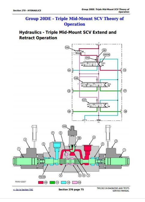
Group 20DE: Triple Mid-Mount SCV Theory of Operation
Hydraulics - Triple Mid-Mount SCV Extend and Retract Operation
Hydraulics - Triple Mid-Mount SCV Neutral Operation
Hydraulics - Triple Mid-Mount SCV Float Operation
Hydraulics - Triple Mid-Mount SCV Flow Control Valve Operation
Group 20DF: Triple Rear SCV Theory of Operation
Hydraulics - Triple Rear SCV Extend and Retract Operation
Hydraulics - Triple Rear SCV Float Operation
Hydraulics - Triple Rear SCV Neutral Operation
Hydraulics - Triple Rear SCV Continuous Detent Operation
Hydraulics - Triple Rear SCV Kick-Out Detent Operation
Hydraulics - Triple Rear SCV No Detent Operation
Hydraulics - Triple Rear SCV Priority Flow Control Valve Operation
Group 20EA: Hydraulic Trailer Brake Theory of Operation
Hydraulics - Hydraulic Trailer Brake Operation
Group 30AA: Schematics
Hydraulics - Functional Schematic
Group 40AA: Component and Connector Information
Hydraulics - Component Information
Group 50AA: Tests and Adjustments
Hydraulics - Prime Hydraulic Pump
Hydraulics - Heating Hydraulic Oil
Hydraulics - Implement Pump Flow Test
Hydraulics - Implement Relief Valve Test
Hydraulics - Implement Relief Valve Adjustment
Hydraulics - Hitch Cylinder Supply Pressure Test
Hydraulics - Hitch Load-Sense Relief Valve Adjustment
Hydraulics - Hitch Surge Relief Valve Test
Hydraulics - Rockshaft Leakage Test
Hydraulics - Rockshaft Lift Cycle Test
Hydraulics - SCV Leak Down Test
Hydraulics - Triple Deluxe Rear SCV Functional Test
Hydraulics - Triple Deluxe Rear SCV Flow Control Test
Hydraulics - Triple Mid-Mount Control Valve Flow Control Test
Hydraulics - Kick-Out Detent Pressure Test
Hydraulics - Hydraulic Trailer Brake Valve Test
Hydraulics - Mid-Mount SCV Cable Adjustment
Hydraulics - Multi-Funtional Control Cable Adjustment (with Secondary Brake)
Hydraulics - Rear SCV Cable Adjustment
Hydraulics - Rockshaft Draft-Sensing and Position Control Cable Adjustment
Hydraulics - Rockshaft Lever Friction Adjustment
Hydraulics - Rockshaft Position-Sensing Feedback Linkage Adjustment
Hydraulics - Rockshaft Draft-Sensing Feedback Linkage Adjustment
Section 290: Cab/Open Operator's Station
Group 05B: General References
Operator Station - Summary of References
Install Test Equipment 90-1
Group 10AA: Calibrations, Preliminary Checks and Operational Checks
Operator Station - HVAC Preliminary Checks
Operator Station - HVAC Operational Checks
Group 20AA: HVAC Theory of Operation
Operator Station - Air Conditioning System Operation
Operator Station - Air Conditioning Compressor Operation
Operator Station - Air Conditioning Condenser Operation
Operator Station - Air Conditioning Dual Pressure Switch Operation
Operator Station - Air Conditioning Evaporator Operation
Operator Station - Air Conditioning Expansion Valve Operation
Operator Station - Air Conditioning Receiver/Dryer Operation
Operator Station - Air Conditioning Temperature Control Switch Operation
Operator Station - Air Conditioning ON/OFF Switch and Temperature Control Knob Operation
Operator Station - Heater Temperature Control Knob Operation
Operator Station - Heating and Ventilation Operation
Group 20BA: Seat Theory of Operation
Operator Station - Air Seat Operation
Operator Station - Mechanical Seat Operation
Group 30AA: Schematics
Operator Station - Schematics
Group 40AA: Component and Connector Information
Operator Station - Component and Connector Information
Group 50AA: Tests and Adjustments
Operator Station - A/C System Pressure Test
Operator Station - A/C System Static Pressure Test
Operator Station - Temperature Drop Test
Section 299: Special Tools
Group 05B: General References
Special Tools - Summary of References
Group 05C: Dealer Fabricated and Service Tools
38H1029
38H1145
38H1147
38H1414
38H1415
38H1416
38H5003
AR52361
AR94522
D01169AA
D05330ST
D15032NU
DFRW126
DFRW133
DFRW183
DFRW213
DFRW227
FKM10002
FKM10302
FKM10303
FKM10305
JDG774
JDG1478
JDG10466
JT02051
JT02063
JT02153
JT02178
JT02180
JT03043
JT03044
JT03051
JT03059
JT03261
JT03262
JT03364
JT03477
JT03478
JT03479
JT03481
JT03481-1
JT03481-3
JT03481-4
JT03520
JT05418
JT05470
JT05471
JT05472
JT05473
JT05474
JT05480
JT05494
JT05497
JT05498
JT05634
JT05685
JT05690
JT05791
JT05832
JT05833
JT05843
JT05845
JT07032
JT07041
JT07115
JT07115 SUP
JT07117
JT07119
JT07148
JT07212
JT07253
KJD10128
RE43774
RE60701
John Deere Tractors 5085E, 5095E, 5100E Diagnosis & Tests Service Technical Manual (TM128219)
![]()