
John Deere Tractors 5065M, 5075M, 5085M, 5095M, 5095MH, 5105ML, 5105M Repair Service Technical Manual (TM102619)
Complete service repair manual for John Deere Tractors 5065M, 5075M, 5085M, 5095M, 5095MH, 5105ML, 5105M (Tier 3/Stage IIIA), with workshop information to maintain, service, repair, and rebuild like professional mechanics.
John Deere Tractors 5085M, 5100M, 5100MH, 5100ML, 5115M Limited workshop service repair manual includes:
* Numbered table of contents easy to use so that you can find the information you need fast.
* Detailed sub-steps expand on repair procedure information
* Numbered instructions guide you through every repair procedure step by step.
* Notes, cautions and warnings throughout each chapter pinpoint critical information.
* Bold figure number help you quickly match illustrations with instructions.
* Detailed illustrations, drawings and photos guide you through every procedure.
* Enlarged inset helps you identify and examine parts in detail.
TM102619 - John Deere Tractors 5065M, 5075M, 5085M, 5095M, 5095MH, 5105ML, 5105M Technical Manual (Repair).PDF
TM102619 - John Deere Tractors 5065M, 5075M, 5085M, 5095M, 5095MH, 5105ML, 5105M Technical Manual (Repair).EPUB
Total Pages: 1,712 pages
File Format: PDF/EPUB/MOBI/AZW (PC/Mac/Android/Kindle/iPhone/iPad; bookmarked, ToC, Searchable, Printable)
Language: English
MAIN SECTIONS
Foreword
General Information
Safety
General Specifications
Fuel and Lubricants
Serial Number Locations
Engine
Engine
Cooling System
Fuel, Air Intake and Exhaust Systems
Fuel System
Throttle Controls
Air Intake System
Air Exhaust System
Electrical System
Battery, Starter and Alternator
Electrical System Components
Wiring Harnesses
Power Train
Separation
SyncShuttle Plus™ Transmission
SyncReverser™ Transmission and PowrReverser™ Transmission
PowrReverser Plus™ Transmission
Clutch Assembly-SyncShuttle Plus™ Transmission
Clutch Assembly-SyncReverser™/PowrReverser™ Transmission
Clutch Assembly-PowrReverser Plus™ Transmission
Differential
Control Valve
Final Drives
Hi-Crop Final Drives
Rear PTO Drive Shaft
Mechanical Front-Wheel Drive
Creeper Assembly
Steering and Brake
Steering Repair
Brake Repair
Hydraulic
Hydraulic Pump and Filter
Hydraulic Oil Cooler
Hitch Valve
Hydraulic Rear Selective Control Valve-Mono-Block Valve
Hydraulic Rear Selective Control Valve-Sectional Valve
Hydraulic Mid-Mount Selective Control Valve-Mono-Block Valve
Hydraulic Mid-Mount Selective Control Valve-Sectional Valve
Hydraulic Lines
Hydraulic Trailer Brake Valve
Miscellaneous
Front Axle-2WD
3-Point Hitch
Fenders
Hood
Operator's Station
Seat and Support
Control Console
Roll-Gard™
Cab Components
Open Operator's Station Components
Air Conditioning System
Heating System
Special Tools
Dealer Fabricated Tools
Service Tools
tm102619 - 5065M and 5075M (IT4/Stage IIIB), 5085M, 5095M, 5095MH, 5105M and 5105ML (Tier 3/Stage IIIA) Tractors Repair Technical Manual
Table of Contents
Foreword
Section 10: General Information
Group 05: Safety
Recognize Safety Information
Handle Fuel Safely—Avoid Fires
Prevent Battery Explosions
Prepare for Emergencies
Prevent Acid Burns
Service and Operate Chemical Sprayers Safely
Handle Chemical Products Safely
Avoid High-Pressure Fluids
Park Machine Safely
Support Machine Properly
Wear Protective Clothing
Work in Clean Area
Service Machines Safely
Work In Ventilated Area
Illuminate Work Area Safely
Replace Safety Signs
Use Proper Lifting Equipment
Remove Paint Before Welding or Heating
Avoid Heating Near Pressurized Fluid Lines
Keep ROPS Installed Properly
Service Tires Safely
Avoid Harmful Asbestos Dust
Practice Safe Maintenance
Use Proper Tools
Decommissioning — Proper Recycling and Disposal of Fluids and Components
Prevent Machine Runaway
Handle Starting Fluid Safely
Service Cooling System Safely
Stay Clear of Rotating Drivelines
Protect Against High Pressure Spray
Construct Dealer-Made Tools Safely
Clean Vehicle of Hazardous Pesticides
Welding Near Electronic Control Units
Live With Safety
Group 10: General Specifications
Regions and Country Versions
Features and Accessories
Machine General Specifications
Service Recommendations for O-Ring Boss Fittings
Service Recommendations For Flat Face O-Ring Seal Fittings
Metric Cap Screw Torque Values—Grade 7
Metric Bolt and Screw Torque Values
Unified Inch Bolt and Screw Torque Values
Glossary of Terms
Group 15: Fuel and Lubricants
Diesel Fuel
Handling and Storing Diesel Fuel
Do Not Use Galvanized Containers
Lubricity of Diesel Fuel
Testing Diesel Fuel
BioDiesel Fuel
Fill Fuel Tank
Diesel Engine Break-In Oil—4 Cylinder Engine
Diesel Engine Oil—5 Cylinder Engine
Diesel Engine Break-In Oil—5 Cylinder Engine
Diesel Engine Oil—4 Cylinder Engine
Oil Filters
Diesel Engine Coolant (engine with wet sleeve cylinder liners)
Operating in Warm Temperature Climates
Additional Information About Diesel Engine Coolants and John Deere LIQUID COOLANT CONDITIONER
Testing Diesel Engine Coolant
Transmission and Hydraulic Oil
Use Correct Transmission/Hydraulic Filter Element
MFWD Axle Housing and Wheel Hub Oil
Grease
Mixing of Lubricants
Alternative and Synthetic Lubricants
Lubricant Storage
Group 20: Serial Number Locations
Serial Numbers
Product Identification Number Location
Engine Serial Number Location
Fuel Injection Pump Serial Number Location
Alternator Identification Number Location
Power Steering Valve Serial Number Location
Starter Serial Number Location—4 Cylinder Engine
Starter Serial Number Location—5 Cylinder Engine
Transmission Serial Number Location
Front Axle (2WD) Serial Number Location
Mechanical Front Wheel Drive (MFWD) Serial Number Location
Air Conditioner Compressor Serial Number Location
Cab Serial Number Location
Section 20: Engine
Group 05: Engine
Service Equipment and Tools
Specifications
John Deere Engine Repair—Use Component Technical Manual
Remove Engine
Install Engine
Group 10: Cooling System
Specifications
Engine Water Pump Repair—Use Component Technical Manual
Drain Coolant
Remove and Install Coolant Recovery Tank
Remove and Inspect Radiator
Install Radiator
Remove and Install Thermostat—4 Cylinder Engine
Remove and Install Thermostat—5 Cylinder Engine
Inspect and Replace Belt Tensioner—4 Cylinder Engine
Inspect and Replace Belt Tensioner—5 Cylinder Engine
Section 30: Fuel, Air Intake and Exhaust Systems
Group 05: Fuel System
Specifications
Injection Pump, Nozzle and Governor Repair
Replace Fuel Gauge Sensor
Remove, Inspect and Install Fuel Tank
Replace Fuel Filter—5 Cylinder Engine
Replace Fuel Filters—4 Cylinder Engine
Remove and Install Fuel Primer Pump Assembly
Remove, Inspect and Install Fuel Cooler
Replace Fuel Strainer and In-Line Check Valve
Inspect and Replace Fuel System Lines—5 Cylinder Engine
Inspect and Replace Fuel System Lines—4 Cylinder PTM (Tier3) Engine
Inspect and Replace Fuel System Lines—4 Cylinder PTE Engine
Inspect and Repair Speed Control Linkage—OOS
Inspect and Repair Speed Control Linkage—Cab
Group 10: Throttle Controls
Throttle Lever Adjustment—OOS
Throttle Lever Adjustment—Cab
Throttle Pedal Adjustment—OOS
Throttle Pedal Adjustment—Cab
Fuel Injection Pump Throttle Cable Adjustment
Group 15: Air Intake System
Turbocharger Repair
Specifications
Other Material
Remove, Inspect and Install Air Cleaner Elements—Axial Type
Remove, Inspect, and Install Air Cleaner Elements—Radial Type
Remove and Install Air Cleaner—Axial Type
Remove and Install Air Cleaner—Radial Type
Remove Turbocharger—5 Cylinder Engine
Install Turbocharger—5 Cylinder Engine
Remove Turbocharger—4 Cylinder Engine
Install Turbocharger—4 Cylinder Engine
Remove, Inspect and Install Charge Air Cooler (CAC)
Group 20: Air Exhaust System
Specifications
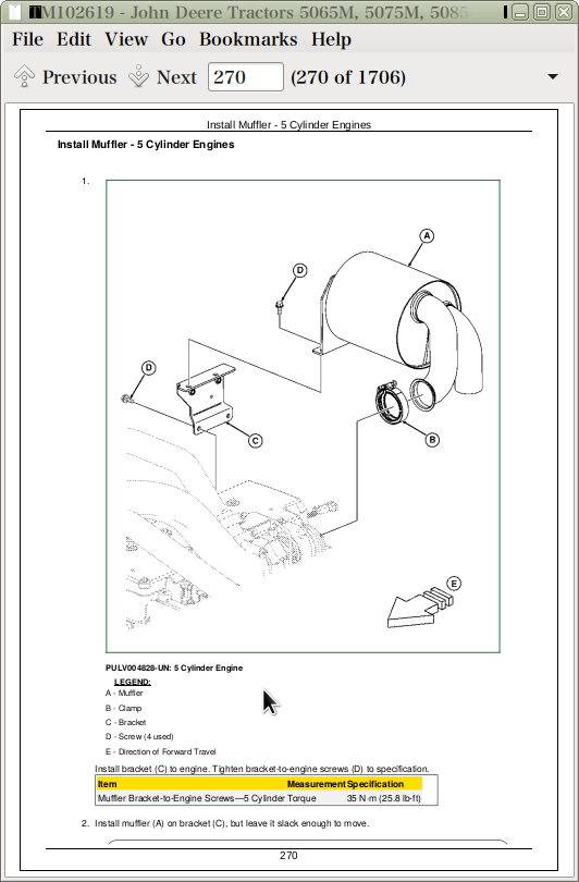
Install Muffler - 5 Cylinder Engines
Install Muffler - 4 Cylinder Engines
Install Vertical Exhaust Pipe—5-Cylinder Engines
Install Vertical Exhaust Pipe - 4 Cylinder Engines
Install Side Exhaust Pipe - 5 Cylinder Engines
Install Side Exhaust Pipe - 4 Cylinder Engines
Section 40: Electrical System
Group 05: Battery, Starter and Alternator
Starter Repair—Use Component Technical Manual
Prevent Battery Explosions
Remove and Install Battery
Remove and Install Starter
Replace Alternator—4 Cylinder Engine
Replace Alternator—5 Cylinder Engine
Group 10: Electrical System Components
Essential Tools
Other Material
Specifications
Servicing Electronic Control Units
Keep Electronic Control Unit Connectors Clean
Replace Air Filter Restriction Switch (B03)
Replace Cold Advance Temperature Sensor (B34)—4 Cylinder PTM Engine
Replace Cold Advance Solenoid (Y09)—4 Cylinder PTM Engine
Replace Coolant Temperature Sensor (B26)—5 Cylinder PTE Engine
Replace Coolant Temperature Sensor (B26)—4 Cylinder PTE Engine
Replace Coolant Temperature Sensor (B41/B02)—4 Cylinder PTM Engine
Replace Fuel Temperature Sensor—4 Cylinder PTE Engine
Replace Fuel Pressure Sensor (B40)—4 Cylinder PTE Engine
Replace Fuel Flow Solenoid (Y12)—4 Cylinder PTM Engine
Replace Engine Crankshaft Speed Sensor (B29)—4 Cylinder PTE Engine
Replace Engine Crankshaft Speed Sensor (B42)—4 Cylinder PTM Engine
Replace Engine Camshaft Speed Sensor (B28)—4 Cylinder PTE Engine
Replace Engine Camshaft Speed Sensor—5 Cylinder Engine
Replace Suction Control Valve—4 Cylinder PTE Engine
Replace Water-in-Fuel Sensor (B24)—4 Cylinder PTE Engine
Replace Engine Oil Pressure Switch (B38)—4 Cylinder PTM Engine
Replace Engine Oil Pressure Switch (B39)—4 Cylinder PTE Engine
Replace Engine Oil Pressure Switch—5 Cylinder Engine
Replace Manifold Air Temperature Sensor (B25)—5 Cylinder Engine
Replace Key Switch
Replace Light Switch
Replace Speakers
Replace Antenna
Replace Turn Signal Switch
Replace Instrument Panel
Replace Rear PTO Switch—OOS
Replace Rear PTO Switch—Cab
Replace Hitch Control Module—Electro-Hydraulic Hitch
Replace EH Hitch Load/Depth Sensor
Replace Hand Throttle Position Sensor (OOS)—PTE Engine
Replace Hand Throttle Position Sensor (Cab)—PTE Engine
Replace Foot Throttle Position Sensor
Replace Neutral Start Switch—SS Plus Transmission
Replace Park Lock Switch—SR, PR and PR Plus Transmission
Replace Speed Lever Neutral Switch (S34)—SR, PR and PR Plus Transmission with Creeper
Replace Creeper Lever Position Sensor (B43)
Replace Fuel Level Sender
Replace Wiper Control Switch
Replace Wiper Motor
Replace Blower Control Switch
Replace A/C On/Off Switch
Replace A/C Deicing Switch (B07)
Replace Blower Motor Resistor
Replace A/C High/Low Pressure Switch
Replace Dome Light
Replace Door Switch
Replace Seat Switch—Cab
Replace Seat Switch—OOS
Replace Electro-Hydraulic Control Unit and Engine Control Unit—Cab
Replace Electro-Hydraulic Control Unit and Engine Control Unit—OOS
Replace Starter Relay
Replace Rear PTO Speed Sensor
Replace Ground Drive PTO Switch (S35)—OOS, Low Profie
Replace EH Hitch Solenoids
Replace Top Shaft Speed Sensor (B09)
Replace Wheel Speed Sensor (B10)
Replace Enable Pressure Sensor—SR, PR and PR Plus Transmission
Replace Transmission Oil Temperature Sensor
Replace Clutch Pedal Position Sensor—SR, PR and PR Plus™ Transmission
Replace EH Hitch Draft Sensor
Replace EH Hitch Position Sensor
Replace Electro-Hydraulic Directional Reverser—PR and PR Plus Transmission
Replace Electro-Hydraulic Directional Reverser—SR Transmission
Replace Brake Pedal Switch
Replace Hi/Lo Shifter Switch—PowrReverser Plus™ Transmission
Replace Mid-Mount Solenoid Switch
Replace EH Hitch External Raise/Lower Switch
Replace Mid-Mount Solenoid
Replace Clutch Enable Solenoid—SR, PR and PR Plus Transmission
Replace Reverse Solenoid—SR, PR and PR Plus Transmission
Replace High Solenoid—PR Plus Transmission
Replace Low Solenoid—SR, PR and PR Plus Transmission
Replace Rear PTO Solenoid
Replace MFWD Solenoid
Replace MFWD Switch
Replace Differential Lock Solenoid
Replace Differential Lock Switch—OOS
Replace Differential Lock Switch—Cab
Replace Seat Height Control Switch
Replace Headlight Bulb
Replace Warning Light Bulb—Cab
Replace Turn/Warning Light and/or Clearance Light Bulb—Cab (Europe)
Replace Tail/Brake Light and/or Turn/Warning Light Bulb—Cab
Replace Tail Light and/or Warning Light Bulb—Open Operator's Station
Replace Turn/Warning Light and/or Clearance Light Bulb—Open Operator's Station (Europe)
Replace Tail/Brake Light and/or Turn/Warning Light Bulb—Open Operator's Station (Europe)
Replace Work Light Bulb—OOS
Replace Work Light Bulb—Cab
Replace Fender Light Bulb—OOS
Replace Loader Light Bulb—If Equipped
Replace Dome Light Bulb—Cab
Replace Controls Illumination Light Bulb—Cab
Replace Rotary Beacon Light Bulb—If Equipped
Group 15: Wiring Harnesses
Service Equipment and Tools
Essential Tools
Replace Connector Body—Blade Terminals
Replace WEATHER PACK™ Connector
Install WEATHER PACK™ Contact
Repair (Pull Type) METRI-PACK™ Connectors
Repair (Push Type) METRI-PACK™ Connectors
Exploded View—CINCH Flexbox Connectors
CINCH™ Flexbox Connectors
Repair DEUTSCH™ Connectors
Replace Headlight Wiring Harness
Replace Convenience Outlet Harness (W005)
Replace Positive Battery Cable (4.5L) (W010)
Replace Positive Battery Cable (3.0L) (W011)
Replace Engine Power Cable (4.5L) (W013)
Replace Engine Power Cable (3.0L) (W014)
Replace Auxiliary Power Strip (Cab) (W016)
Replace Negative Battery Cable (W020)
Replace Operator Station Ground Cable (W021)
Replace Radiator Ground Cable (W022)
Replace Left Loader Light Harness (W101)
Replace Right Loader Light Harness (W102)
Replace Loader Light Switch Harness (W103)
Replace Right Beacon Light Harness (OOS) (W104) / Left Beacon Light Harness (OOS) (W105)
Replace Left Rear Work Light Harness (OOS) (W106)
Replace Right Rear Work Light Harness (OOS) (W107)
Replace Canopy Warning Light Harness (OOS) (W108)
Replace Right Front Inner Roof Work Light Harness (Cab) (W109)
Replace Left Front Inner Roof Work Light Harness (Cab) (W110)
Replace Right Fender Work Light Harness (OOS) (W111)
Replace Left Fender Work Light Harness (OOS) (W112)
Replace Left Fender Work Light and Hitch Switch Harness (OOS) (W113)
Replace Right Rear Inner Roof Work Light Harness (Cab) (W114)
Replace Left Rear Inner Roof Work Light Harness (Cab) (W115)
Replace Right Rear Tail Light Harness (W116)
Replace Left Rear Tail Light Harness (W117)
Replace Backup Alarm Harness (OOS, SS) (W201)
Replace Backup Alarm Harness (Cab, SS) (W202)
Replace Engine Harness (4.5L PTE) (W307)
Replace Engine Harness (4.5L PTM) (W308)
Replace Engine Harness (3.0L PTE) (W309)
Replace Engine Injector Harness (3.0L PTE) (W310)
Replace Engine Injector Harness (4.5L PTE) (W311)
Replace Engine Electronic Unit Pump Harness (3.0L PTE) (W312)
Replace Chassis Harness (OOS, PTE, PR, SR, EH 3PT) (W300)
Replace Chassis Harness (OOS, PTE, SR, Mech 3PT) (W301)
Replace Chassis Harness (OOS, PTE, SS, Mech 3PT) (W302)
Replace Chassis Harness (OOS, PTM, SS, Mech 3PT) (W303)
Replace Chassis Harness (OOS, PTM, PR, SR, EH 3PT) (W304)
Replace Chassis Harness (OOS, PTM, SR, Mech 3PT) (W305)
Replace Chassis Harness (OOS, PTE, PR, SR, Creeper, EH 3PT) (W316)
Replace Chassis Harness (OOS, PTM, PR, SR, Creeper, EH 3PT) (W317)
Replace Chassis Harness (OOS, PR/SR, Secondary Brake, GD PTO) (W318)
Replace Chassis Harness (OOS, SS, Secondary Brake, Ground Drive PTO) (W319)
Replace Chassis Harness (OOS, SS, Low Profile) (W320)
Replace Chassis Harness (OOS, PR, Low Profile) (W321)
Replace Glow Plug Harness (3.0L, PTE) (W410)
Replace Cab Harness (PTE, PR, EH 3PT) (W500)
Replace Cab Harness (PTM, PR, SR, EH 3PT) (W501)
Replace Cab Harness (PTE, SS, Mech 3PT) (W502)
Replace Cab Harness (PTM, SS, Mech 3PT) (W503)
Replace Cab Harness (PTM, SR, Mech 3PT) (W504)
Replace Cab Harness (PTE, Mech 3PT) (W505)
Replace Cab Harness (PTM, PR, Creeper) (W508)
Replace Cab Harness (PTE, PR, Creeper) (W509)
Replace Cab Harness (SS, Secondary Brake, Ground Drive PTO) (W510)
Replace Cab Harness (PR/SR, Secondary Brake, Ground Drive PTO) (W511)
Replace Transmission Harness (PR, SR) (W573)
Replace Transmission Harness (SS) (W574)
Replace Transmission Harness (SS, License Light) (W575)
Replace Transmission Harness (PR, SR, Creeper) (W577)
Replace Transmission Harness (PR/SR, License Light, GD PTO) (W578)
Replace Mid-Mount SCV Harness (Cab) (W701)
Replace Mid-Mount SCV Harness (OOS) (W702)
Replace Hitch Harness (W875)
Replace Right Fender Hitch Switch Harness (W876)
Replace Front Console Harness (Cab, PTM/PTE, PR) (W900)
Replace Front Console Harness (Cab, PTM/PTE, SS) (W901)
Replace Front Console Harness (Cab, PTM/PTE, SR) (W902)
Replace Front Console Harness (Cab, SS, Ground Drive PTO) (W905)
Replace Front Console Harness (Cab, PR/SR, Ground Drive PTO) (W906)
Replace Roof Harness (W920)
Replace Air Seat Harness (Cab) (W930)
Section 50: Power Train
Group 05: Separation
Specifications
Remove, Inspect and Repair Speed and Range Shift Levers—SS Transmission (Cab) (—Dec. 2011)
Remove, Inspect, and Repair Speed and Range Shift Levers—SS Transmission (Cab) (Dec. 2011—)
Remove, Inspect and Repair Speed and Range Shift Levers—SS Transmission (OOS) (—Dec. 2011)
Remove, Inspect, and Repair Speed and Range Shift Levers—SS Transmission (OOS) (Dec. 2011—)
Remove, Inspect and Repair Speed and Range Shift Levers—SR and PR Transmission (Cab) (—Dec. 2011)
Remove, Inspect, and Repair Speed and Range Shift Levers—SR and PR Transmission (Cab) (Dec. 2011—)
Remove, Inspect and Repair Speed and Range Shift Levers—SR and PR Transmission (OOS) (—Dec. 2011)
Remove, Inspect, and Repair Speed and Range Shift Levers—SR and PR Transmission (OOS) (Dec. 2011—)
Remove, Inspect and Repair Speed and Range Shift Levers—PR Plus Transmission (Cab) (—Dec. 2011)
Remove, Inspect, and Repair Speed and Range Shift Levers—PR Plus Transmission (Cab) (Dec. 2011—)
Remove, Inspect and Repair Speed and Range Shift Levers—PR Plus Transmission (OOS) (—Dec. 2011)
Remove, Inspect, and Repair Speed and Range Shift Levers—PR Plus Transmission (OOS) (Dec. 2011—)
Remove and Install Drive Train Assembly
Separate Transmission Case from Differential Case
Remove and Inspect Transmission
Install Transmission
Disassemble and Inspect Transmission Lube Pump
Assemble Transmission Lube Pump
Group 10: SyncShuttle Plus™ Transmission
Essential Tools
Specifications
Disassemble, Inspect and Assemble Top Shaft Assembly—SyncShuttle Plus™ Transmission
Disassemble, Inspect and Assemble Speed Shift Assembly—SyncShuttle Plus™ Transmission
Disassemble, Inspect and Assemble Differential Drive Shaft—SyncShuttle Plus™ Transmission
Disassemble, Inspect and Repair Range Shift Assembly—SyncShuttle Plus™ Transmission
Disassemble, Inspect and Assemble Park Lock Shift Rail Assembly—SyncShuttle Plus™ Transmission (—Dec. 2011)
Disassemble, Inspect, and Assemble Park Lock Shift Rail Assembly—SyncShuttle Plus™ Transmission (Dec. 2011—)
Disassemble, Inspect and Assemble Countershaft Assembly—SyncShuttle Plus™ Transmission
Park Lock Adjustment Procedure—SyncShuttle Plus™ Transmission (—Dec. 2011)
Park Lock Adjustment Procedure—SyncShuttle Plus™ Transmission (Dec. 2011—)
Group 15: SyncReverser™ Transmission and PowrReverser™ Transmission
Essential Tools
Specifications
Exploded View—Synchronizer
Disassemble, Inspect and Assemble Top Shaft Assembly—SyncReverser™ Transmission and PowrReverser™ Transmission
Disassemble, Inspect and Assemble Speed Shift Assembly—SyncReverser™ Transmission and PowrReverser™ Transmission
Disassemble, Inspect and Assemble Differential Drive Shaft—SyncReverser™ Transmission and PowrReverser™ Transmission
Disassemble, Inspect and Assemble Differential Drive Shaft—SyncReverser™ Transmission and PowrReverser™ Transmission
Disassemble, Inspect and Repair Range Shift Assembly—SyncReverser™ Transmission and PowrReverser™ Transmission
Disassemble, Inspect and Assemble Park Lock Shift Rail Assembly—SyncReverser™ Transmission and PowrReverser™ Transmission (—Dec. 2011)
Disassemble, Inspect, and Assemble Park Lock Shift Rail Assembly—SyncReverser™ Transmission and PowrReverser™ Transmission (Dec. 2011—)
Disassemble, Inspect and Assemble Countershaft Assembly—SyncReverser™ Transmission and PowrReverser™ Transmission
Park Lock Adjustment Procedure—SyncReverser™ Transmission and PowrReverser™ Transmission (—Dec. 2011)
Park Lock Adjustment Procedure—SyncReverser™ Transmission and PowrReverser™ Transmission (Dec. 2011—)
Group 20: PowrReverser Plus™ Transmission
Essential Tools
Specifications
Exploded View—Synchronizer
Disassemble, Inspect and Assemble Top Shaft Assembly—PowrReverser Plus™ Transmission
Disassemble, Inspect and Assemble Speed Shift Assembly—PowrReverser Plus™ Transmission
Disassemble, Inspect and Assemble Differential Drive Shaft—PowrReverser Plus™ Transmission
Disassemble, Inspect and Repair Range Shift Assembly—PowrReverser Plus™ Transmission
Disassemble, Inspect and Assemble Park Lock Shift Rail Assembly—PowrReverser Plus™ Transmission (—Dec. 2011)
Disassemble, Inspect, and Assemble Park Lock Shift Rail Assembly—PowrReverser Plus™ Transmission (Dec. 2011—)
Disassemble, Inspect and Assemble Countershaft Assembly—PowrReverser Plus™ Transmission
Park Lock Adjustment Procedure—PowrReverser Plus™ Transmission (—Dec. 2011)
Park Lock Adjustment Procedure—PowrReverser Plus™ Transmission (Dec. 2011—)
Group 25: Clutch Assembly—SyncShuttle Plus™ Transmission
Specifications
Remove and Install Clutch and Shaft Assembly—SyncShuttle Plus™ Transmission
Disassemble, Inspect and Assemble Clutch Shaft Assembly—SyncShuttle Plus™ Transmission
Disassemble, Inspect and Assemble Pump Idler Shaft Assembly—SyncShuttle Plus™ Transmission
Disassemble and Inspect Clutch Pack—SyncShuttle Plus™ Transmission
Assemble Clutch Pack—SyncShuttle Plus™ Transmission
Remove, Inspect and Repair Clutch Pedal and Linkage—SyncShuttle Plus™ Transmission
Group 30: Clutch Assembly—SyncReverser™/PowrReverser™ Transmission
Specifications
Remove and Install Clutch and Shaft Assembly—SyncReverser™ and PowrReverser™ Transmission
Disassemble, Inspect and Assemble Low Clutch Shaft Assembly—SyncReverser™ and PowrReverser™ Transmission
Disassemble, Inspect and Assemble Reverse Clutch Assembly—SyncReverser™ and PowrReverser™ Transmission
Disassemble, Inspect and Assemble Reverse Idler Shaft Assembly—SyncReverser™ and PowrReverser™ Transmission
Disassemble and Inspect Clutch Pack—SyncReverser™ and PowrReverser™ Transmission
Assemble Clutch Pack—SyncReverser™ and PowrReverser™ Transmission
Remove, Inspect and Repair Clutch Pedal and Linkage—SyncReverser™ and PowrReverser™ Transmission
Group 35: Clutch Assembly—PowrReverser Plus™ Transmission
Specifications
Remove and Install Clutch and Shaft Assembly—PowrReverser Plus™ Transmission
Disassemble, Inspect and Assemble Low Clutch Shaft Assembly—PowrReverser Plus™ Transmission
Disassemble, Inspect and Assemble Reverse Clutch Assembly—PowrReverser Plus™ Transmission
Disassemble, Inspect and Assemble High Clutch Assembly—PowrReverser Plus™ Transmission
Disassemble and Inspect Clutch Pack—PowrReverser Plus™ Transmission
Assemble Clutch Pack—PowrReverser Plus™ Transmission
Remove, Inspect and Repair Clutch Pedal and Linkage—PowrReverser Plus™ Transmission
Remove and Install Hydraulic Accumulator—PowrReverser Plus™ Transmission
Group 40: Differential
Essential Tools
Service Equipment and Tools
Other Material
Specifications
Remove and Install Differential Assembly
Disassemble, Inspect and Assemble Differential Assembly
Remove and Inspect Differential Drive Shaft
Differential Cone Point Adjustment
Differential Backlash Adjustment
Group 45: Control Valve
Specifications
Remove, Inspect and Install Control Valve - SS Plus Transmission—Cab
Remove, Inspect and Install Control Valve - SS Plus Transmission—OOS
Disassemble, Inspect and Repair Control Valve - SS Plus Transmission
Remove, Inspect and Install Control Valve - SR, PR and PR Plus Transmission—Cab
Remove, Inspect and Install Control Valve - SR, PR and PR Plus Transmission—OOS
Disassemble, Inspect and Repair Control Valve - SR, PR and PR Plus Transmission
Group 50: Final Drives
Service Equipment and Tools
Other Material
Specifications
Remove and Install Final Drive Assembly
Remove and Inspect Planetary Drive Assembly
Install Planetary Drive Assembly
Remove, Inspect, and Install Axle Shaft Assembly
Group 55: Hi-Crop Final Drives
Other Material
Specifications
Remove and Install Hi-Crop Axle Assembly
Remove, Inspect and Install Hi-Crop Final Drive Assembly
Group 60: Rear PTO Drive Shaft
Service Equipment and Tools
Other Material
Specifications
Remove, Inspect and Install Rear PTO Lever and Linkage—Cab
Remove, Inspect and Install Rear PTO Lever and Linkage—OOS
Remove, Inspect and Install Rear PTO Lever and Linkage—Low Profile
PTO 540/540E Shift Lever and Linkage Adjustment
Remove and Install Rear PTO Drive Shaft Assembly
Disassemble, Inspect and Assemble Standard (540) Rear PTO Drive Shaft Assembly
Disassemble, Inspect and Assemble 540/540E Rear PTO Drive Shaft Assembly
Disassemble, Inspect and Assemble 540/540E/1000 with Exchangeable Rear PTO Drive Shaft Assembly
Disassemble, Inspect and Assemble 540/540E/1000 Rear PTO Drive Shaft Assembly
Disassemble, Inspect and Assemble 540/540E/Ground Drive PTO Shaft Assembly
Disassemble, Inspect and Assemble Rear PTO Clutch Assembly
Group 65: Mechanical Front-Wheel Drive
Service Equipment and Tools
Other Material
Specifications
MFWD Axle Repair—Use Component Technical Manual
Remove and Install MFWD Gearbox
Disassemble, Inspect and Install MFWD Idler Shaft Assembly
Disassemble, Inspect and Install MFWD Output Shaft Assembly
Remove, Inspect and Install MFWD Drive Shaft
Remove and Install MFWD Axle Housing Assembly
Group 70: Creeper Assembly
Other Material
Specifications
Remove, Inspect and Install Creeper Control Lever and Cable—SS Plus Transmission (OOS)
Remove, Inspect and Install Creeper Control Lever and Cable—SR/PR/PR Plus Transmission (OOS)
Remove, Inspect and Install Creeper Control Lever and Cable—SS PlusTransmission (Cab)
Remove, Inspect and Install Creeper Control Lever and Cable—SR/PR/PR Plus Transmission (Cab)
Remove, Inspect and Install Creeper Gear Assembly
Creeper Interlock Shimming Procedure
Section 60: Steering and Brake
Group 05: Steering Repair
Other Material
Specifications
Remove and Install Steering Valve
Remove and Install Tilt/Telescoping Steering Column
Remove and Install Steering Cylinder—2WD Axle
Disassemble, Inspect, and Assemble Steering Cylinder—2WD Axle
Remove, Inspect and Install Tie Rod Assembly—2WD Axle
Remove and Install Steering Cylinder— MFWD Axle
Disassemble, Inspect, and Assemble Steering Cylinder—MFWD Axle
Remove, Inspect and Install Tie Rod Assembly—MFWD Axle
Inspect and Replace Steering Hydraulic Lines
Group 10: Brake Repair
Service Equipment and Tools
Other Material
Specifications
Remove and Install Brake Valve and Pedals
Disassemble and Inspect Brake Valve
Brake Valve Sectional View
Assemble Brake Valve
Remove and Inspect Brakes
Install Brakes
Remove, Inspect and Install Secondary Brakes
Secondary Brake Adjustment
Inspect and Replace Brake Hydraulic Lines
Brake Pedal Adjustment
Bleed Brakes
Section 70: Hydraulic
Group 05: Hydraulic Pump and Filter
Service Equipment and Tools
Specifications
Remove and Install Hydraulic Pumps
Remove and Install Hydraulic Pump External Components
Disassemble, Inspect and Assemble Hydraulic Pumps
Remove and Install Hydraulic Oil Filter and Manifold
Group 10: Hydraulic Oil Cooler
Remove, Inspect and Install Hydraulic Oil Cooler
Group 15: Hitch Valve
Other Material
Specifications
Inspect and Repair Control Lever and Cables—Mechanical Hitch (OOS)
Inspect and Repair Control Lever and Linkages—Mechanical Hitch (Low Profile)
Inspect and Repair Control Lever and Cables—Mechanical Hitch (Cab)
Inspect and Repair Hitch Control Linkage—Mechanical Hitch
Inspect and Repair Hitch Control Linkage—Mechanical Hitch (Low Profile)
Remove and Install Hitch Valve—Mechanical Hitch
Remove and Install Hitch Valve—Electro-Hydraulic Hitch
Replace Main/Implement Relief Valve—Mechanical Hitch
Replace Shock Relief Valve—Mechanical Hitch
Remove, Inspect and Install Rate-of-Drop Valve—Mechanical Hitch
Remove, Inspect and Install Check Valve—Mechanical Hitch
Hitch Valve Repair—Electro-Hydraulic Hitch
Hitch Valve Exploded View—Electro-Hydraulic Hitch
Hitch Valve Repair—Mechanical Hitch
Hitch Valve Exploded View—Mechanical Hitch
Inspect and Repair Draft Sensing Assembly—Mechanical Hitch
Inspect and Repair Draft Sensing Assembly—Electro-Hydraulic Hitch
Remove, Inspect and Install Lift Arms
Remove, Inspect and Install Lift Cylinders
Mechanical Hitch Adjustment
Group 20A: Hydraulic Rear Selective Control Valve—Mono-Block Valve
Other Material
Specifications
Inspect and Repair SCV Levers and Linkage—Open Operator's Station
Inspect and Repair SCV Levers and Linkage—Low Profile
Inspect and Repair SCV Levers and Linkage—Cab
Remove and Install Rear Selective Control Valve (SCV)
Disassemble, Inspect and Assemble Single Rear Selective Control Valve (SCV)
Disassemble, Inspect and Assemble Dual Rear Selective Control Valve (SCV)
Triple Rear Selective Control Valve (SCV) Sectional View
Disassemble, Inspect and Assemble Triple Rear Selective Control Valve (SCV)
SCV Diverter Plug Operation
Rear SCV Control Cable Adjustment
Rear Triple Deluxe SCV Kick-Out Relief Valve Adjustment
Group 20B: Hydraulic Rear Selective Control Valve—Sectional Valve
Other Material
Specifications
Inspect and Repair SCV Levers and Linkage (Open Operator Station)
Inspect and Repair SCV Levers and Linkages (Cab)
Remove and Install Rear Selective Control Valve (SCV)
Disassemble, Inspect, and Assemble Dual Rear Selective Control Valve (SCV)
Disassemble, Inspect, and Assemble Triple Rear Selective Control Valve (SCV)
SCV Diverter Plug Operation
Rear SCV Control Cable Adjustment
Group 25A: Hydraulic Mid-Mount Selective Control Valve—Mono-Block Valve
Other Material
Specifications
Inspect and Repair Joystick and Linkage
Remove and Install Mid-Mount Selective Control Valve (SCV)
Disassemble, Inspect and Assemble Dual Mid-Mount Selective Control Valve (SCV)
Disassemble, Inspect and Assemble Triple Mid-Mount Selective Control Valve (SCV)
SCV Diverter Plug Operation
Mid-Mount SCV Control Cable Adjustment
Group 25B: Hydraulic Mid-Mount Selective Control Valve—Sectional Valve
Other Material
Specifications
Inspect and Repair Multi-Function Lever and Linkage
Remove and Install Mid-Mount Selective Control Valve (SCV)
Disassemble, Inspect, and Assemble Mid-Mount Selective Control Valve (SCV)
SCV Diverter Plug Operation
Mid-Mount SCV Control Cable Adjustment
Group 30: Hydraulic Lines
Specifications
Inspect and Replace Hydraulic Lines
Group 35: Hydraulic Trailer Brake Valve
Specifications
Remove, Inspect and Install Hydraulic Trailer Brake (HTB) Valve
Disassemble, Inspect and Assemble Hydraulic Trailer Brake (HTB) Valve
Inspect and Replace Hydraulic Trailer Brake (HTB) Valve Lines
Section 80: Miscellaneous
Group 05: Front Axle—2WD
Service Equipment and Tools
Specifications
Remove and Install Front Axle—2WD
Inspect and Replace Pivot Pin and Bushings—2WD Axle
Remove and Install Spindle Assembly—2WD Axle
Inspect and Replace Spindle Shaft Bushings—2WD Axle
Inspect and Replace Front Wheel Bearings
Group 10: 3-Point Hitch
Specifications
Remove 3-Point Hitch Linkage
Install Lower Draft Links
Install Lift Links
Install Center Link
Remove and Install Drawbar and Support
Remove and Install Drawbar Support (No Trailer Hitch)
Remove and Install Drawbar Support (Trailer Hitch)
Remove and Install Trailer Hitch
Checking the Manually-Operated Hitch for Wear
Group 15: Fenders
Other Material
Specifications
Remove and Install Fenders—Open Operator's Station
Remove and Install Fenders—Low Profile
Remove and Install Fenders—Cab
Group 20: Hood
Specifications
Remove and Install Hood
Section 90: Operator's Station
Group 05: Seat and Support
Specifications
Remove and Install Seat and Support—Open Operator's Station
Remove and Install seat and Support—Cab
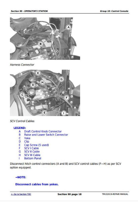
Group 10: Control Console
Specifications
Remove and Install Right-Side Control Console — OOS, Mechanical Hitch Control
Remove and Install Right-Side Control Console — OOS, Electro-Hydraulic Hitch Control
Remove and Install Right-Side Control Console — Low Profile
Remove and Install Right-Side Control Console — Cab
Remove and Install Left-Side Control Console—Cab
Remove and Install Front Control Console
Remove and Install Cowl Cover
Group 15: Roll-Gard™
Specifications
Remove and Install Roll-Gard™
Remove and Install Front Roll-Gard™—Low Profile
Remove and Install Rear Roll-Gard™—Low Profile
Group 20: Cab Components
Essential Tools
Service Equipment and Tools
Other Material
Specifications
Remove, Inspect, and Install Cab Interior Recirculating Air Filters
Remove, Inspect, and Install Exterior Cab Intake Air Filter
Remove and Install Headliner
Remove and Install Instructional Seat
Remove and Install Left-Side Upholstery
Remove and Install Right-Side Upholstery
Remove and Install Windshield
Remove and Install Front Lower Windows
Remove and Install Rear Lower Window
Remove and Install Rear Upper Window
Remove and Install Side Windows
Remove and Install Cab Doors
Remove and Install Inner Roof for Air Conditioning Housing Repair
Remove Cab
Install Cab
Park Position Indicator Installation and Adjustment Procedure—Cab (—Dec. 2011)
Park Position Indicator Installation and Adjustment Procedure—Cab (Dec. 2011—)
Group 25: Open Operator's Station Components
Other Material
Specifications
Remove Open Operator’s Station
Install Open Operator's Station
Park Position Indicator Installation and Adjustment Procedure—OOS (—Dec. 2011)
Park Position Indicator Installation and Adjustment Procedure—OOS (Dec. 2011—)
Group 30: Air Conditioning System
Essential Tools
Service Equipment and Tools
Other Material
Specifications
Adjust A/C Deicing Switch
Recover/Recycle Air Conditioning Refrigerant
Replace Air Conditioning Receiver/Dryer
Remove, Inspect, and Install Air Conditioning Condenser
Remove, Inspect, and Install Air Conditioning Compressor
Test Volumetric Efficiency of Compressor
Test Compressor Shaft Seal Leakage
Disassemble and Assemble Compressor Clutch
Disassemble, Inspect, and Assemble Compressor
Check Compressor Clutch Hub Clearance
Inspect Compressor Manifold
Remove, Inspect, and Install Compressor Relief Valve
Remove and Install HVAC Housing Cover
Remove Blower Motors
Remove Evaporator/Heater Core
Leak Test Evaporator/Heater Core
Install Evaporator/Heater Core
Service Expansion Valve
Expansion Valve Bench Test
Refrigerant Oil Information
Check Compressor Oil Charge
Determine Correct Refrigerant Oil Charge
Add Refrigerant Oil to System
System Information
Flush Air Conditioning System
Evacuate Air Conditioning System
Charge Air Conditioning System
Group 35: Heating System
Adjust Heater Temperature Control Cable
Replace Heater Temperature Control Cable
Remove Heater Control Valve
Leak Test Heater Control Valve
Install Heater Control Valve
Section 99: Special Tools
Group 05: Dealer Fabricated Tools
DFLV1A-Final Drive Turning Tool
DFRW20—Compressor Holding Fixture
DFT1162—Snap Ring Removal Tool
Group 10: Service Tools
D15032NU — Vacuum Pump Kit
D05330ST — Supplemental Accessory Kit
JDG364 — Weatherpack Extraction Tool
JDG776 — Weatherpack Extractor, 56-Series Metripack, Blue Handle
JDG777 — Extractor, Weatherpack Narrow
JDG783 — Packard Crimping Tool
JDG10562 — Nut Wrench
JDG10810 — Shaft Socket
JDG10940 — Transmission Top Shaft Socket
JT01767 — Supplemental Lawn and Grounds Care Products Hydraulic Fitting Kit
JT02081—Halogen Leak Detector
JT02098 — Air Conditioning Flushing Kit
JT07115 — Master Hydraulic Test Kit
JT07115 SUP — Supplemental Master Hydraulic Test Kit
JT07195B — Technicians Electrical Repair Kit
JT02095 — R134a Start-Up Kit
JT07196 — Technicians A/C R134a Service Kit
JT07120 — Load Valve Assembly
JT03105 — Connector (1/2 (m) NPT X 1/4 (f) NPT)
JT03261 — Coupler (1/4 (m) NPT)
JT05412 — Industrial Universal Pressure Test Kit
JT05470 — Universal Pressure Test Kit
JT05497 — Hose Assembly, 3048 mm (120 in.) Long
JT07117 — Three-Gauge Manifold
JT03348 — Tee Fitting (1/2 (f) NPT x 1/2 (f) NPT x 1/2 (f) NPT)
R36659 — Hydraulic Jumper Hose (3 ft)
John Deere Tractors 5065M, 5075M, 5085M, 5095M, 5095MH, 5105ML, 5105M Repair Service Technical Manual (TM102619)
![]()