
John Deere Tractors 5085M, 5100M, 5100MH, 5100ML, 5115M, 5115ML Repair Service Technical Manual (TM134319)
Complete service repair manual for John Deere Tractors 5085M, 5100M, 5100MH, 5100ML, 5115M, 5115ML (FT4) (S.N. MY2014-, MY2014-Dec-2014, MY2016-), with workshop information to maintain, repair, and service like professional mechanics.
John Deere Tractors 5085M, 5100M, 5100MH, 5100ML, 5115M Limited workshop service repair manual includes:
* Numbered table of contents easy to use so that you can find the information you need fast.
* Detailed sub-steps expand on repair procedure information
* Numbered instructions guide you through every repair procedure step by step.
* Notes, cautions and warnings throughout each chapter pinpoint critical information.
* Bold figure number help you quickly match illustrations with instructions.
* Detailed illustrations, drawings and photos guide you through every procedure.
* Enlarged inset helps you identify and examine parts in detail.
tm134319 - 5085M, 5100M, 5100MH, 5100ML, 5115M, and 5115ML (FT4) Tractors Repair Technical Manual.pdf
tm134319 - 5085M, 5100M, 5100MH, 5100ML, 5115M, and 5115ML (FT4) Tractors Repair Technical Manual.epub
Total Pages: 1,515 pages
File Format: PDF/EPUB/MOBI/AZW (PC/Mac/Android/Kindle/iPhone/iPad; bookmarked, ToC, Searchable, Printable)
Language: English
MAIN SECTIONS
Foreword
General Information
Safety
General Specifications
Fuels and Lubricants
Serial Number Locations
Engine
Engine
Cooling System
Fuel, Air Intake, Exhaust, and Cooling
Fuel System
Air Intake System
Exhaust System
Electrical
Battery, Starter and Alternator
Electrical System Components
Wiring Harnesses
Drive Systems and Transmissions
Separation
SS Transmission
PR Transmission
PR Plus Transmission
Clutch Assembly-SS Transmission
Clutch Assembly-PR Transmission
Clutch Assembly-PR Plus Transmission
Differential
Control Valve
Final Drives
Hi-Crop Final Drives
Rear PTO Drive Shaft
Mechanical Front-Wheel Drive
Creeper Assembly
Steering and Brakes
Steering Repair
Brake Repair
Hydraulics
Hydraulic Pump and Filter
Hydraulic Oil Cooler
Hitch Valve
Hydraulic Rear Selective Control Valve
Hydraulic Mid-Mount Selective Control Valve
Hydraulic Lines
Front Hitch
Miscellaneous
Front Axle-2WD
3-Point Hitch
Fenders
Hood
Step Assembly
Wheels
SCR Covers and Shields
Cab/Open Operator’s Station
Seat and Support
Control Console
Roll-Gard
Cab Components
Open Operator Station Components
Air Conditioning System
Heating System
Special Tools
Dealer Fabricated Tools
tm134319 - 5085M, 5100M, 5100MH, 5100ML, 5115M, and 5115ML (FT4) Tractors Repair Technical Manual
Table of Contents
Foreword
Section 10: General Information
Group 05: Safety
Work In Ventilated Area
Recognize Safety Information
Avoid Backover Accidents
Prevent Machine Runaway
Avoid Contact with Agricultural Chemicals
Clean Vehicle of Hazardous Pesticides
Use a Safety Chain
Work in Clean Area
Decommissioning: Proper Recycling and Disposal of Fluids and Components
Avoid Harmful Asbestos Dust
Avoid Hot Exhaust
Clean Exhaust Filter Safely
Handle Fuel Safely—Avoid Fires
Prepare for Emergencies
Handle Fluids Safely—Avoid Fires
Avoid High-Pressure Fluids
Install All Guards
Use Proper Lifting Equipment
Illuminate Work Area Safely
Live With Safety
Service Machines Safely
Support Machine Properly
Remove Paint Before Welding or Heating
Park Machine Safely
Stay Clear of Rotating Drivelines
Follow Safety Instructions
Use Proper Tools
Service Tires Safely
Keep ROPS Installed Properly
Construct Dealer-Made Tools Safely
Practice Safe Maintenance
Understand Signal Words
Replace Safety Signs
Avoid Heating Near Pressurized Fluid Lines
Wear Protective Clothing
Handling Batteries Safely
Service Accumulator Systems Safely
Handle Agricultural Chemicals Safely
Service Cooling System Safely
Use Steps and Handholds Correctly
Deliver Safely
Transport Tractor Safely
Servicing Electronic Control Units
Welding Near Electronic Control Units
Keep Electronic Control Unit Connectors Clean
Service Front-Wheel Drive Tractor Safely
Do Not Open High-Pressure Fuel System
Group 10: General Specifications
Regions and Country Versions
Features and Accessories
Machine General Specifications
Drain and Refill Capacities
Service Recommendations for O-Ring Boss Fittings
Service Recommendations For Flat Face O-Ring Seal Fittings
Metric Bolt and Screw Torque Values
Unified Inch Bolt and Screw Torque Values
Glossary of Terms
Trademarks
Group 15: Fuels and Lubricants
Alternative and Synthetic Lubricants
Diesel Engine Coolant (engine with wet sleeve cylinder liners)
Operating in Warm Temperature Climates
John Deere COOL-GARD™ II Coolant Extender
Water Quality for Mixing with Coolant Concentrate
Testing Coolant Freeze Point
Diesel Exhaust Fluid (DEF) — Use in Selective Catalytic Reduction (SCR) Equipped Engines
Disposal of Diesel Exhaust Fluid (DEF)
Refilling Diesel Exhaust Fluid (DEF) Tank
Storing Diesel Exhaust Fluid (DEF)
Testing Diesel Exhaust Fluid (DEF)
Extended Diesel Engine Oil Service Intervals
Diesel Engine Oil — Interim Tier 4, Final Tier 4, Stage IIIB, and Stage IV
Engine Oil and Filter Service Intervals — Interim Tier 4, Final Tier 4, Stage IIIB, and Stage IV Engines
John Deere Break-In Plus™ Engine Oil — Interim Tier 4, Final Tier 4, Stage IIIB, and Stage IV
Oil Filters
Fuel Filters
Diesel Fuel
Handling and Storing Diesel Fuel
Lubricity of Diesel Fuel
Testing Diesel Fuel
BioDiesel Fuel
Minimizing the Effect of Cold Weather on Diesel Engines
Supplemental Diesel Fuel Additives
Grease
Mixing of Lubricants
Lubricant Storage
Transmission, Steering, Brake, Hydraulic, and Gear Case Oil
Oilscan™ and CoolScan™
Group 20: Serial Number Locations
Serial Numbers
Product Identification Number
Engine Serial Number
Alternator Identification Number Location
Power Steering Valve Serial Number Location
Starter Serial Number Location
Transmission Serial Number
Front Axle (2WD) Serial Number Location
Mechanical Front Wheel Drive (MFWD) Serial Number Location
Air Conditioner Compressor Serial Number Location
Cab Serial Number
Section 20: Engine
Group 05: Engine
Specifications
Service Equipment and Tools
Other Material
John Deere Engine Repair—Use Component Technical Manual
Remove Engine
Install Engine
Group 10: Cooling System
Specifications
Engine Water Pump Repair—Use Component Technical Manual
Drain Coolant
Remove and Install Coolant Recovery Tank
Remove and Inspect Radiator
Install Radiator
Remove and Install Thermostat
Inspect and Replace Belt Tensioner
Remove and Install Viscous Clutch
Section 30: Fuel, Air Intake, Exhaust, and Cooling
Group 05: Fuel System
Specifications
Injection Pump, Nozzle, and Governor Repair—Use Component Technical Manual
Remove, Inspect, and Install Main Fuel Tank
Remove, Inspect, and Install Auxiliary Fuel Tank
Replace Fuel Filters
Remove and Install Fuel Primer Pump Assembly
Remove, Inspect, and Install Fuel Cooler
Replace Fuel Strainer and In-Line Check Valve
Inspect and Replace Fuel System Lines
Group 15: Air Intake System
Specifications
Turbocharger Repair
Remove, Inspect, and Install Air Cleaner Elements—Axial Type
Remove and Install Air Cleaner—Axial Type
Remove and Install Air Heater Housing
Remove and Install Turbocharger
Remove, Inspect, and Install Charge Air Cooler (CAC)
Group 20: Exhaust System
Specifications
Service Equipment and Tools
Aftertreatment Device Repair and Adjustment—Use Component Technical Manual
DEF Dosing Aftertreatment Devices Repair and Adjustment—Use Component Technical Manual
Remove and Install DEF Tank
Remove and Install DEF Dosing Injector
Remove and Install Aftertreatment Device (ATD)
Remove and Install DEF Decomposition Tube
Remove and Install Vertical Exhaust Pipe
Remove and Install Side Discharge Exhaust
Remove and Install Selective Catalyst Reduction (SCR) Canister
Section 40: Electrical
Group 05: Battery, Starter and Alternator
Starter Repair—Use Component Technical Manual
Prevent Battery Explosions
Remove and Install Battery
Remove and Install Starter
Remove and Install Alternator
Group 10: Electrical System Components
Essential or Recommended Tools
Other Material
Specifications
Servicing Electronic Control Units
Keep Electronic Control Unit Connectors Clean
Replace Engine Sensors
Remove and Install Electrical Shifter Pod
Replace Key Switch
Replace Light Switch
Replace Roll Mode Switch
Replace Exhaust Filter Cleaning Switch
Replace Power Shuttle Control
Replace Beacon Light Switch
Replace Speakers
Remove and Install Subwoofer
Replace Antenna
Replace Multifunction Switch
Replace Instrument Panel
Replace Rear PTO ON/OFF Switch—OOS
Replace Rear PTO ON/OFF Switch—Cab
Replace Hitch Control Module—Electrohydraulic Hitch
Replace EH Hitch Load/Depth Sensor
Replace Hand Throttle Position Sensor (OOS)
Replace Hand Throttle Position Sensor (Cab)
Replace Foot Throttle Position Sensor
Replace Neutral Start Switch
Replace Reverse Switch
Replace Park Switch
Replace Speed Lever Neutral Switch
Replace Creeper Lever Position Sensor
Replace Fuel Level Sender
Replace Front Wiper Switch
Replace Rear Wiper Switch
Replace AUX and USB Jack
Replace Front Wiper Motor
Replace Blower Control Switch
Replace A/C Deicing Switch
Replace A/C On/Off Switch
Replace HVAC Resistor
Replace A/C High/Low Pressure Switch
Replace Dome Light
Replace Left Door Switch
Replace Seat Switch—Cab
Replace Seat Switch—OOS
Replace Electrohydraulic Control (EHC) Unit—Cab
Replace Electrohydraulic Control (EHC) Unit—OOS
Replace Engine Control Unit (ECU)
Replace Neutral Start Relay
Replace Rear PTO Speed Sensor
Replace EH Hitch Solenoids
Replace Top Shaft Speed Sensor
Replace Wheel Speed Sensor
Replace Enable Pressure Sensor
Replace Hydraulic Oil Temperature Sensor
Replace Clutch Pedal Position Sensor
Replace Hitch Draft Sensor
Replace Hitch Position Sensor
Replace Forward Neutral Reverse (FNR) Switch
Replace Brake Pedal Switch
Replace High/Low Shifter Switch—PowrReverser Plus Transmission
Replace Mid-Mount SCV 3rd Function Switch
Replace Left External Raise/Lower Switch
Replace Mid-Mount Solenoid
Replace Clutch Enable Solenoid Valve
Replace Transmission Reverse Solenoid Valve
Replace Transmission Forward (High) Solenoid Valve
Replace Transmission Forward (Low) Solenoid Valve
Replace PTO Solenoid Valve
Replace MFWD Solenoid
Replace MFWD Switch
Replace Differential Lock Solenoid Valve
Replace Differential Lock Switch—OOS
Replace Differential Lock Switch—Cab
Replace Seat Height Control Switch
Replace Headlight Bulb
Replace Warning Light Bulb—Cab
Replace Tail/Brake Light and/or Turn/Warning Light Bulb—Cab
Replace Tail Light and/or Warning Light Bulb—Open Operator Station
Replace Work Light Bulb—OOS
Replace Work Light Bulb—Cab
Replace Fender Light Bulb—OOS
Replace Loader Light Bulb—If Equipped
Replace Dome Light Bulb—Cab
Replace Controls Illumination Light Bulb—Cab
Replace Map Light—Cab
Replace Map Light Switch—Cab
Replace Rotary Beacon Light Bulb—If Equipped
Compressor Inlet Sensor
Replace DEF Dosing Unit Pump
Replace DEF Tank Header
Group 15: Wiring Harnesses
Essential or Recommended Tools
Service Equipment and Tools
Specifications
Replace Connector Body—Blade Terminals
Replace WEATHER PACK™ Connector
Install WEATHER PACK™ Contact
Repair (Pull Type) METRI-PACK™ Connectors
Repair (Push Type) METRI-PACK™ Connectors
Exploded View—CINCH Flexbox Connectors
CINCH™ Flexbox Connectors
Repair DEUTSCH™ Connectors
Replace W015 Key Switch Wiring Harness
Replace W016 Auxiliary Power Strip Harness
Replace W021 Operator Station Ground Cable
Replace W022 Clutch Assembly Harness
Replace W027 DEF Harness
Replace W029 Overhead Console Harness
Replace W030 Multifunction Switch Jumper Harness
Replace W031 Radio Auxiliary Jack and USB Harness
Replace W035 Convenience Outlet Harness
Replace W050 Positive Battery Cable
Replace W051 Negative Battery Cable
Replace W052 Engine Power Cable
Replace W053 Cab Power Harness
Replace W100 Hood Harness
Replace W101 Left Loader Light Harness
Replace W102 Right Loader Light Harness
Replace W103 Loader Light Switch Harness
Replace W104 Right Beacon Light Harness
Replace W105 Left Beacon Light Harness
Replace W106 Left Rear Work Light Harness
Replace W107 Right Rear Work Light Harness
Replace W108 Deluxe Canopy Warning Light Harness
Replace W110 Brake Light Harness
Replace W111 Right Work Light Fender Extension Harness
Replace W112 Left Fender Extension Harness
Replace W113 Left Work Light and Hitch Switch Harness
Replace W120 Right Beacon Light Harness
Replace W121 Left Beacon Light Harness
Replace W124 Antenna Cable
Replace W201 Back-Up Alarm Harness (OOS, SS)
Replace W202 Back-Up Alarm Harness (Cab, SS)
Replace W310 Chassis Harness (OOS, SS)
Replace W311 Chassis Harness (OOS, PR)
Replace W312 OOS Chassis Harness (Low Profile, PR Transmission)
Replace W400 Engine Harness
Replace W401 Exhaust Filter Temperature Sensor Harness
Replace W509 Cab Chassis Harness (SS Transmission)
Replace W510 Cab Chassis Harness (PR Transmission)
Replace W577 Transmission Harness (SS Transmission)
Replace W578 Transmission Harness (PR Transmission)
Replace W707 Mid-Mount SCV Harness
Replace W708 Multi-Function Control Lever Switch Harness
Replace W875 Hitch Harness/Draft Sensor
Replace W876 Right Hand Fender EH Hitch Switch Harness
Replace W906 Front Console Harness (SS Transmission)
Replace W907 Front Console Harness (PR Transmission)
Replace W925 Roof Harness
Replace W926 Deluxe Roof Harness
Section 50: Drive Systems and Transmissions
Group 05: Separation
Specifications
Service Equipment and Tools
Other Material
Remove, Inspect, and Repair Speed and Range Shift Levers—SS and PR Transmission (Cab)
Remove, Inspect, and Repair Speed and Range Shift Levers—SS and PR Transmission (OOS)
Remove, Inspect, and Repair Speed and Range Shift Levers—PR Plus Transmission (Cab)
Remove, Inspect, and Repair Speed and Range Shift Levers—PR Plus Transmission (OOS)
Remove and Install Drive Train Assembly
Separate Transmission Case from Differential Case
Remove and Inspect Transmission
Install Transmission
Disassemble and Inspect Transmission Lube Pump
Assemble Transmission Lube Pump
Group 10: SS Transmission
Specifications
Service Equipment and Tools
Other Material
Disassemble, Inspect, and Assemble Top Shaft Assembly—SS Transmission
Disassemble, Inspect, and Assemble Speed Shift Assembly—SS Transmission
Disassemble, Inspect, and Assemble Differential Drive Shaft—SS Transmission
Disassemble, Inspect, and Repair Range Shift Assembly—SS Transmission
Disassemble, Inspect, and Assemble Park Lock Shift Rail Assembly
Disassemble, Inspect, and Assemble Countershaft Assembly—SS Transmission
Park Lock Adjustment Procedure
Group 15: PR Transmission
Specifications
Service Equipment and Tools
Essential or Recommended Tools
Other Material
Disassemble, Inspect, and Assemble Top Shaft Assembly—PR Transmission
Disassemble, Inspect, and Assemble Speed Shift Assembly—PR Transmission
Disassemble, Inspect, and Assemble Differential Drive Shaft—PR Transmission
Disassemble, Inspect, and Repair Range Shift Assembly—PR Transmission
Disassemble, Inspect, and Assemble Park Lock Shift Rail Assembly—PR Transmission
Disassemble, Inspect, and Assemble Countershaft Assembly—PR Transmission
Park Lock Adjustment Procedure—PR Transmission
Group 20: PR Plus Transmission
Specifications
Service Equipment and Tools
Essential or Recommended Tools
Other Material
Disassemble, Inspect, and Assemble Top Shaft Assembly—PR Plus Transmission
Disassemble, Inspect, and Assemble Speed Shift Assembly—PR Plus Transmission
Disassemble, Inspect, and Assemble Differential Drive Shaft—PR Plus Transmission
Disassemble, Inspect, and Repair Range Shift Assembly—PR Plus Transmission
Disassemble, Inspect, and Assemble Park Lock Shift Rail Assembly—PR Plus Transmission
Disassemble, Inspect, and Assemble Countershaft Assembly—PR Plus Transmission
Park Lock Adjustment Procedure—PR Plus Transmission
Group 25: Clutch Assembly—SS Transmission
Specifications
Essential or Recommended Tools
Other Material
Remove and Install Clutch and Shaft Assembly—SS Transmission
Disassemble, Inspect, and Assemble Clutch Shaft Assembly—SS Transmission
Disassemble, Inspect, and Assemble Pump Idler Shaft Assembly—SS Transmission
Disassemble and Inspect Clutch Pack—SS Transmission
Assemble Clutch Pack—SS Transmission
Remove, Inspect, and Repair Clutch Pedal and Linkage—SS Transmission
Group 30: Clutch Assembly—PR Transmission
Specifications
Essential or Recommended Tools
Other Material
Remove and Install Clutch and Shaft Assembly—PR Transmission
Disassemble, Inspect, and Assemble Low Clutch Shaft Assembly—PR Transmission
Disassemble, Inspect, and Assemble Reverse Clutch Assembly—PR Transmission
Disassemble, Inspect, and Assemble Reverse Idler Shaft Assembly—PR Transmission
Disassemble and Inspect Clutch Pack—PR Transmission
Assemble Clutch Pack—PR Transmission
Remove, Inspect, and Repair Clutch Pedal and Linkage—PR Transmission
Group 35: Clutch Assembly—PR Plus Transmission
Specifications
Essential or Recommended Tools
Other Material
Remove and Install Clutch and Shaft Assembly—PR Plus Transmission
Disassemble, Inspect, and Assemble Low Clutch Shaft Assembly—PR Plus Transmission
Disassemble, Inspect, and Assemble Reverse Clutch Assembly—PR Plus Transmission
Disassemble, Inspect, and Assemble High Clutch Assembly—PR Plus Transmission
Disassemble and Inspect Clutch Pack—PR Plus Transmission
Assemble Clutch Pack—PR Plus Transmission
Remove, Inspect, and Repair Clutch Pedal and Linkage—PR Plus Transmission
Remove and Install Hydraulic Accumulator
Group 40: Differential
Specifications
Essential or Recommended Tools
Other Material
Remove and Install Differential Assembly
Disassemble, Inspect, and Assemble Differential Assembly
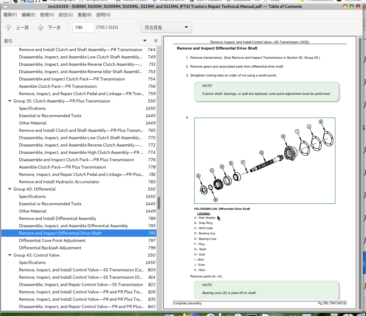
Remove and Inspect Differential Drive Shaft
Differential Cone Point Adjustment
Differential Backlash Adjustment
Group 45: Control Valve
Specifications
Remove, Inspect, and Install Control Valve—SS Transmission (Cab)
Remove, Inspect, and Install Control Valve—SS Transmission (OOS)
Disassemble, Inspect, and Repair Control Valve—SS Transmission
Remove, Inspect, and Install Control Valve—PR and PR Plus Transmission (Cab)
Remove, Inspect, and Install Control Valve—PR and PR Plus Transmission (OOS)
Disassemble, Inspect, and Repair Control Valve—PR and PR Plus Transmission
Group 50: Final Drives
Specifications
Essential or Recommended Tools
Other Material
Remove and Install Final Drive Assembly
Remove and Inspect Planetary Drive Assembly
Install Planetary Drive Assembly
Remove, Inspect, and Install Axle Shaft Assembly
Group 55: Hi-Crop Final Drives
Specifications
Other Material
Remove and Install Hi-Crop Axle Assembly
Remove, Inspect, and Install Hi-Crop Final Drive Assembly
Group 60: Rear PTO Drive Shaft
Specifications
Service Equipment and Tools
Other Material
Remove, Inspect, and Install Rear PTO Lever and Linkage—Cab
Remove, Inspect, and Install Rear PTO Lever and Linkage—OOS
PTO 540/540E Shift Lever and Linkage Adjustment
Remove and Install Rear PTO Drive Shaft Assembly
Disassemble, Inspect, and Assemble Standard (540) Rear PTO Drive Shaft Assembly
Disassemble, Inspect, and Assemble 540/540E Rear PTO Drive Shaft Assembly
Disassemble, Inspect, and Assemble 540/540E/1000 with Exchangeable Rear PTO Drive Shaft Assembly
Disassemble, Inspect, and Assemble 540/540E/1000 Rear PTO Drive Shaft Assembly
Disassemble, Inspect, and Assemble 540/540E/Ground Drive PTO Shaft Assembly
Disassemble, Inspect, and Assemble Rear PTO Clutch Assembly
Group 65: Mechanical Front-Wheel Drive
Specifications
Other Material
MFWD Axle Repair—Use Component Technical Manual
Remove and Install MFWD Gearbox
Disassemble, Inspect, and Install MFWD Idler Shaft Assembly
Disassemble, Inspect, and Install MFWD Output Shaft Assembly
Remove, Inspect, and Install MFWD Drive Shaft
Remove and Install MFWD Axle Housing Assembly
Group 70: Creeper Assembly
Specifications
Remove, Inspect, and Install Creeper Control Lever and Cable—SS Transmission (OOS)
Remove, Inspect, and Install Creeper Control Lever and Cable—PR and PR Plus Transmission (OOS)
Remove, Inspect, and Install Creeper Control Lever and Cable—SS Transmission (Cab)
Remove, Inspect, and Install Creeper Control Lever and Cable—PR and PR Plus Transmission (Cab)
Remove, Inspect, and Install Creeper Gear Assembly
Creeper Interlock Shimming Procedure
Section 60: Steering and Brakes
Group 05: Steering Repair
Other Material
Specifications
Remove and Install Steering Wheel
Remove and Install Steering Valve
Remove and Install Tilt/Telescoping Steering Column
Remove and Install Steering Cylinder—2WD Axle
Disassemble, Inspect, and Assemble Steering Cylinder—2WD Axle
Remove, Inspect, and Install Tie Rod Assembly—2WD Axle
Remove and Install Steering Cylinder— MFWD Axle
Disassemble, Inspect, and Assemble Steering Cylinder—MFWD Axle
Remove, Inspect, and Install Tie Rod Assembly—MFWD Axle
Inspect and Replace Steering Hydraulic Lines
Group 10: Brake Repair
Specifications
Service Equipment and Tools
Other Material
Remove and Install Brake Valve and Pedals
Disassemble and Inspect Brake Valve
Brake Valve Sectional View
Assemble Brake Valve
Remove and Inspect Brakes
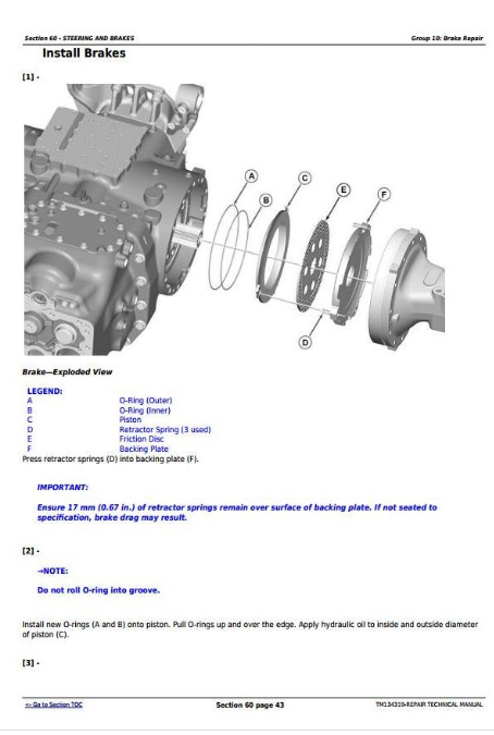
Install Brakes
Inspect and Replace Brake Hydraulic Lines
Brake Pedal Adjustment
Bleed Brakes
Section 70: Hydraulics
Group 05: Hydraulic Pump and Filter
Specifications
Remove and Install Hydraulic Pumps
Remove and Install Hydraulic Pump External Components
Disassemble, Inspect, and Assemble Hydraulic Pumps
Remove and Install Hydraulic Oil Filter and Manifold
Group 10: Hydraulic Oil Cooler
Remove, Inspect, and Install Hydraulic Oil Cooler
Group 15: Hitch Valve
Other Material
Specifications
Inspect and Repair Control Levers and Cables—Mechanical Hitch (OOS)
Inspect and Repair Control Lever and Linkages—Mechanical Hitch (Low Profile)
Inspect and Repair Control Levers and Cables—Mechanical Hitch (Cab)
Inspect and Repair Mechanical Hitch Control Linkage
Remove and Install Mechanical Hitch Valve
Remove and Install Electrohydraulic Hitch Valve
Electrohydraulic Hitch Valve Repair
Mechanical Hitch Valve Repair
Inspect and Repair Draft Sensing Assembly—Mechanical Hitch
Inspect and Repair Draft Sensing Assembly—Electrohydraulic Hitch
Remove, Inspect, and Install Lift Arms
Remove, Inspect, and Install Lift Cylinders
Mechanical Hitch Adjustment
Group 20: Hydraulic Rear Selective Control Valve
Specifications
Other Material
Inspect and Repair SCV Levers and Linkage (Open Operator Station)
Inspect and Repair SCV Levers and Linkage (Low Profile)
Inspect and Repair SCV Levers and Linkages (Cab)
Remove and Install Rear Selective Control Valve (SCV)
Disassemble, Inspect, and Assemble Dual Rear Selective Control Valve (SCV)
Disassemble, Inspect, and Assemble Triple Rear Selective Control Valve (SCV)
Rear SCV Control Cable Adjustment
Group 25: Hydraulic Mid-Mount Selective Control Valve
Specifications
Other Material
Inspect and Repair Multi-Function Lever and Linkage
Remove and Install Mid-Mount Selective Control Valve (SCV)
Disassemble, Inspect, and Assemble Dual Mid-Mount Selective Control Valve (SCV)
Disassemble, Inspect, and Assemble Triple Mid-Mount Selective Control Valve (SCV)
Mid-Mount SCV Control Cable Adjustment
Group 30: Hydraulic Lines
Specifications
Inspect or Replace Hydraulic Lines
Group 40: Front Hitch
Specifications
Remove Front Hitch
Install Front Hitch
Remove Front Hitch Cylinders
Install Front Hitch Cylinders
Front Hitch Joint Repair
Section 80: Miscellaneous
Group 05: Front Axle—2WD
Service Equipment and Tools
Specifications
Remove and Install Front Axle—2WD
Inspect and Replace Pivot Pin and Bushings—2WD Axle
Remove and Install Spindle Assembly—2WD Axle
Inspect and Replace Spindle Shaft Bushings—2WD Axle
Inspect and Replace Front Wheel Bearings
Group 10: 3-Point Hitch
Specifications
Remove 3-Point Hitch Linkage
Install Lower Draft Links
Install Lift Links
Install Center Link
Remove and Install Drawbar and Support
Checking the Drawbar for Wear
Proper Use of Drawbar
Group 15: Fenders
Specifications
Welding Near Electronic Control Units
Remove and Install Fenders—OOS
Remove and Install Fenders—Cab
Remove and Install Fender Extension—OOS
Remove and Install Fender Extension—Cab
Group 20: Hood
Remove and Install Hood
Group 25: Step Assembly
Remove and Install Step Assembly––OOS
Remove and Install Step Assembly––Cab
Group 30: Wheels
Specifications
Jacking Up Tractor––Lifting Points
Tighten Bolts––Front Axle
Tighten Bolts––Rear Axle
Remove and Install Front Wheel
Remove and Install Rear Wheel
Group 35: SCR Covers and Shields
Remove and Install SCR Covers and Shields––OOS
Remove and Install SCR Covers and Shields––Cab
Section 90: Cab/Open Operator’s Station
Group 05: Seat and Support
Specifications
Remove and Install Seat and Support—Open Operator Station
Remove and Install Seat and Support—Cab
Group 10: Control Console
Specifications
Remove and Install Right-Hand Control Console—OOS, Mechanical Hitch Control
Remove and Install Right-Hand Control Console—OOS, Electrohydraulic Hitch Control
Remove and Install Right-Side Control Console—Low Profile
Remove and Install Right-Hand Control Console—Cab, Mechanical Hitch Control
Remove and Install Right-Hand Control Console—Cab, Electrohydraulic Hitch Control
Remove and Install Left-Hand Control Console—Cab
Remove and Install Front Control Console
Remove and Install Cowl Cover
Group 15: Roll-Gard
Specifications
Remove and Install Roll-Gard
Group 20: Cab Components
Essential or Recommended Tools
Service Equipment and Tools
Other Material
Specifications
Remove, Inspect, and Install Cab Interior Recirculating Air Filters
Remove, Inspect, and Install Exterior Cab Intake Air Filter
Remove and Install Headliner
Remove and Install Instructional Seat
Remove and Install Left-Hand Upholstery
Remove and Install Right-Hand Upholstery
Remove and Install Windshield
Remove and Install Front Lower Windows
Remove and Install Rear Lower Window
Remove and Install Rear Upper Window
Remove and Install Side Windows
Remove and Install Cab Doors
Remove and Install Inner Roof for Air Conditioning Housing Repair
Remove and Install Front Overhead Console
Remove Cab
Install Cab
Park Position Indicator Installation and Adjustment Procedure—Cab
Group 25: Open Operator Station Components
Specifications
Remove Open Operator Station
Install Open Operator Station
Park Position Indicator Installation and Adjustment—OOS
Group 30: Air Conditioning System
Essential or Recommended Tools
Service Equipment and Tools
Other Material
Specifications
Adjust Air Conditioning Deicing Switch
Recover/Recycle Air Conditioning Refrigerant
Replace Air Conditioning Receiver/Dryer
Remove, Inspect, and Install Air Conditioning Condenser
Remove, Inspect, and Install Air Conditioning Compressor
Test Volumetric Efficiency of Compressor
Test Compressor Shaft Seal Leakage
Disassemble and Assemble Compressor Clutch
Disassemble, Inspect, and Assemble Compressor
Check Compressor Clutch Hub Clearance
Inspect Compressor Manifold
Remove and Install HVAC Housing Cover
Remove Blower Motors
Remove Evaporator/Heater Core
Leak Test Evaporator/Heater Core
Install Evaporator/Heater Core
Service Expansion Valve
Expansion Valve Bench Test
Refrigerant Oil Information
Check Compressor Oil Charge
Determine Correct Refrigerant Oil Charge
Add Refrigerant Oil to System
System Information
Flush Air Conditioning System
Evacuate Air Conditioning System
Charge Air Conditioning System
Group 35: Heating System
Adjust Heater Temperature Control Cable
Replace Heater Temperature Control Cable
Remove Heater Control Valve
Leak Test Heater Control Valve
Install Heater Control Valve
Section 99: Special Tools
Group 05: Dealer Fabricated Tools
DFLV1A-Final Drive Turning Tool
DFRW20—Compressor Holding Fixture
DFT1162—Snap Ring Removal Tool
John Deere Tractors 5085M, 5100M, 5100MH, 5100ML, 5115M, 5115ML Repair Service Technical Manual (TM134319)
![]()