
John Deere Tractors 5070M, 5080M, 5090M, 5100M Repair Service Manual (TM402019)
Complete service repair manual for John Deere Tractors 5090M, 5100M, 5070M, 5080M, 5090M, 5100M (2WD/MFWD), with all the shop information to maintain, repair, and rebuild like professional mechanics.
John Deere Tractors 5090M, 5100M, 5070M, 5080M, 5090M, 5100M workshop service repair manual includes:
* Numbered table of contents easy to use so that you can find the information you need fast.
* Detailed sub-steps expand on repair procedure information
* Numbered instructions guide you through every repair procedure step by step.
* Notes, cautions and warnings throughout each chapter pinpoint critical information.
* Bold figure number help you quickly match illustrations with instructions.
* Detailed illustrations, drawings and photos guide you through every procedure.
* Enlarged inset helps you identify and examine parts in detail.
TM402019 - John Deere Tractors 5070M, 5080M, 5090M & 5100M Technical Manual (Repair).PDF
Total Pages: 1,337 pages
File Format: PDF (bookmarked, ToC, Searchable, Printable, high quality)
Language: English
MAIN SECTIONS
Foreword
Safety
Safety Measures
General Information
Specifications
Tune-Up
Predelivery Inspection
Engine
Removal and Installation of Components
Fuel, Air Intake, Cooling and Exhaust Systems
Removal and Installation of Components
Speed Control Linkage
Fuel System
Air Intake System
Cooling System
Cold-Weather Starting Aids
Exhaust System
Electrical System
Connectors
Alternator
Starting Motor
Electrical Components
Power Train
Removal and Installation of Components
Transmission Shift Controls
Transmission - Reconditioning
SyncReverser™ and PowrReverser™ Transmissions - Clutches
PowrReverser™ Plus Transmission - Clutches
Control Valve
Creeper Transmission
Drive Systems
Removal and Installation of Components
U-Jointed Shafts and Torsion Damper
Front-Wheel Drive Clutch
Differential
Final Drives
Rear PTO
Front PTO
Steering and Brakes
Hydrostatic Steering
Brakes
Hydraulic Trailer Brake
Air Brake System
Hydraulic System
Tandem Pump and Filter
Hydraulic Oil Coolers
Hitch Valve
Valve Block Assembly with M-SCVs
Valve Block Assembly with M-ICVs
Hydraulic Lines
Miscellaneous
Removal and Installation of Components
Front Axle
Three-Point Hitch
Front and Rear Wheels
Trailer Mounting and Swinging Drawbar
Front Loader
Operator`s Cab
Removal and Installation of Components
Air-Conditioning System
Heating System
Seats
Operator`s Cab
Special Tools
Special Tools (Dealer-Fabricated)
Special Tools (Available as Spare Parts)
tm401919 - Tractors5070M, 5080M, 5090M and 5100M Diagnostics
Table of Contents
Foreword
Section 210: General Information
Group 05: Safety
Safety Information
Recognize Safety Information
”Important” Information
”Note” Information
Prevent Machine Runaway
Handle Fluids Safely—Avoid Fires
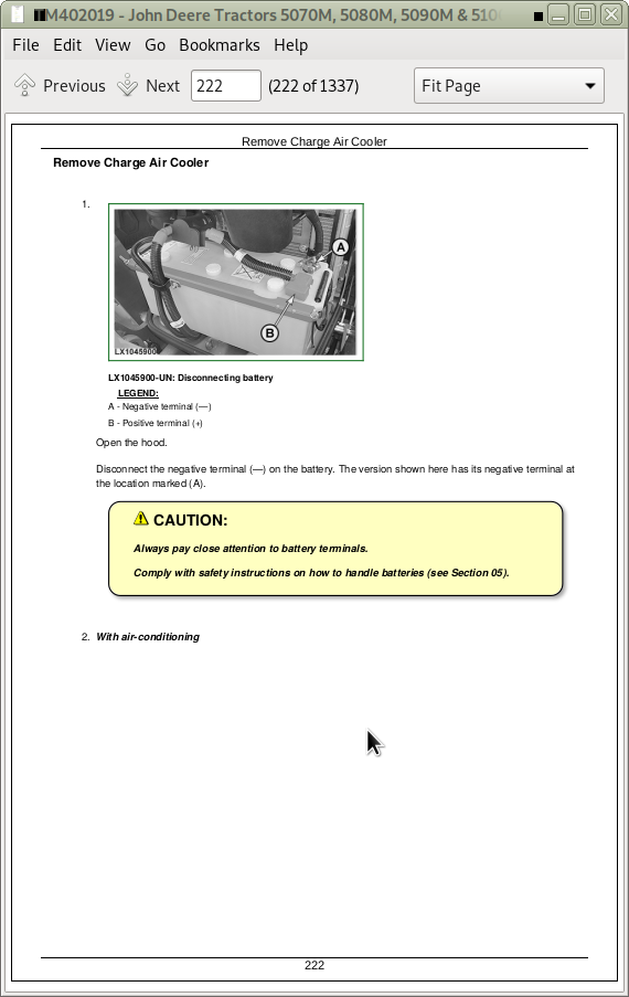
Prevent Battery Explosions
Prepare for Emergencies
Prevent Acid Burns
Avoid High-Pressure Fluids
Service Cooling System Safely
Remove Paint Before Welding or Heating
Avoid Heating Near Pressurized Fluid Lines
Work In Ventilated Area
Wear Protective Clothing
Practice Safe Maintenance
Park Machine Safely
Use Proper Lifting Equipment
Construct Dealer-Made Tools Safely
Support Machine Properly
Work in Clean Area
Illuminate Work Area Safely
Service Machines Safely
Use Proper Tools
Service Tires Safely
Service Front-Wheel Drive Tractor Safely
Safety Information - Air Brake System
Avoid Eye Contact With Radar
Keep ROPS Installed Properly
Replace Safety Signs
Dispose of Waste Properly
Live With Safety
Safety Measures on Electronic Control Units
Safety Instructions for Replacing a Halogen Bulb
Safety Instructions for Replacing Xenon (HID) Bulbs and Ballast Units
Group 10: General References
General Information - General References, Summary of References
General Information - Transmission and Hydraulic System, Introductory Checks
General Information - Inch Bolt and Cap Screws, Torque Values
General Information - Metric Bolt and Cap Screws, Torque Values
General Information - Hydraulic System Inch Fittings, Torque Values
General Information - Hydraulic System Metric Fittings, Torque Values
General Information - Electrical System, Component Identification Table
General Information - Electrical System, How to Read a Diagnostic Schematic
General Information - Electrical System, Lead Numbers and Color Codes
General Information - Electrical System, Symbols in Schematic, Wiring and Harness Diagrams
General Information - Electrical System, Troubleshooting Unsolved Problems
General Information - Electrical System, Worksheet for Circuit/Harness Test
General Information - Electrical System, Visual Check
General Information - Electrical System, Electrical Circuit Malfunctions
General Information - Electrical System, Seven-Step Test Procedure
General Information - Hydraulic System, Symbols in Circuit Diagrams
General Information - Country Version
Section 211: Diagnostics
Group CCU: CCU Code Diagnostics
CCU 000100.01 - Engine Oil Pressure Switch, Engine Oil Pressure Very Low
CCU 000100.04 - Engine Oil Pressure Switch, Open Circuit
CCU 000110.00 - Coolant Temperature Sensor, Temperature Very High
CCU 000110.03 - Coolant Temperature Sensor, Voltage Out of Range High
CCU 000110.04 - Coolant Temperature Sensor, Voltage Out of Range Low
CCU 000110.16 - Coolant Temperature Sensor, Temperature High
CCU 000237.02 - VIN Information, Mismatch
CCU 000237.14 - VIN Information, System De-Activated
CCU 000237.31 - VIN Information, Incorrect
CCU 000569.05 - Differential Lock Solenoid Valve, Fault
CCU 000628.02 - Control Unit Internal Fault
CCU 000629.12 - Control Unit Fault
CCU 000630.14 - Rear PTO Speed Out of Range
CCU 000676.03 - Inlet Air Heater Relay Not Activated, Current Present
CCU 000676.05 - Inlet Air Heater Relay Activated, No Current Present
CCU 001638.00 - Transmission Oil Temperature Very High
CCU 001638.03 - Transmission Oil Temperature Sensor, Voltage Too High
CCU 001638.04 - Transmission Oil Temperature Sensor, Voltage Too Low
CCU 001638.16 - Transmission Oil Temperature High
CCU 001883.00 - Rear PTO Speed Too High
CCU 001883.01 - Rear PTO Speed Too Low
CCU 002818.31 - Operator Presence Switch Not Activated
CCU 003509.03 - 5-volt Supply Voltage of Sensors, Voltage Too High
CCU 003509.04 - 5-volt Supply Voltage of Sensors, Voltage Too Low
CCU 523839.02 - Switch for Park Brake Indicator Light, Fault
CCU 523907.02 - Rear PTO Preselector Switch, Fault
CCU 523908.02 - Switches for Remote Control of Rear PTO (Right and Left), Fault
CCU 524016.04 - ELX Supply Voltage Too Low
CCU 524037.02 - Front-Wheel Drive Switch, Fault
CCU 524223.03 - Differential Lock Switch, Fault
CCU 524224.14 - Rear PTO Switch, Fault
CCU 524235.05 - Front-Wheel Drive Solenoid Valve, Circuit Fault
CCU 524252.05 - Rear PTO Solenoid Valve, Circuit Fault
CCU 524255.31 - INFORMATION FOR OPERATOR: Rear PTO Preselector Switch is Activated
CCU 600006.31 - Diagnostic Trouble Code Not Known
Group HCU: HCU Code Diagnostics
HCU 000190.02 - Engine Speed Too Low During Calibration
HCU 000629.12 - Control Unit Fault
HCU 000630.13 - Error During Hitch Calibration
HCU 001638.02 - Transmission Oil Temperature Too Low During Calibration
HCU 001873.02 - Hitch Position Sensor, Circuit Fault During Calibration
HCU 001873.03 - Hitch Position Sensor, Voltage Too High
HCU 001873.04 - Hitch Position Sensor, Voltage Too Low
HCU 001873.11 - Hitch Position Sensor, Fault During Calibration
HCU 001873.13 - Hitch Position Sensor, Fault During Calibration
HCU 001881.03 - Draft Sensor, Voltage Too High
HCU 001881.04 - Draft Sensor, Voltage Too Low
HCU 001881.13 - Draft Sensor, Fault During Calibration
HCU 003509.03 - 5-volt Supply Voltage of Sensors, Voltage Too High
HCU 003509.04 - 5-volt Supply Voltage of Sensors, Voltage Too Low
HCU 521000.02 - Switch for Remote Control of Hitch (Left or Right), Circuit Fault
HCU 521000.31 - Switch for Remote Control of Hitch (Left or Right), Fault
HCU 521001.02 - Solenoid Valve for Raising (Hitch), Current Too High During Calibration
HCU 521001.05 - Solenoid Valve for Raising (Hitch), Current Too Low
HCU 521001.06 - Solenoid Valve for Raising (Hitch), Current Too High
HCU 521001.07 - Solenoid Valve for Raising (Hitch), Fault During Calibration
HCU 521001.11 - Solenoid Valve for Raising (Hitch), Fault During Calibration
HCU 521001.13 - Solenoid Valve for Raising (Hitch), Fault During Calibration
HCU 521002.05 - Solenoid Valve for Lowering (Hitch), Current Too Low
HCU 521002.06 - Solenoid Valve for Lowering (Hitch), Current Too High
HCU 521002.07 - Solenoid Valve for Lowering (Hitch), Fault During Calibration
HCU 521002.11 - Solenoid Valve for Lowering (Hitch), Fault During Calibration
HCU 521002.13 - Solenoid Valve for Lowering (Hitch), Fault During Calibration
HCU 523832.03 - Rate-of-Drop Potentiometer, Voltage Too High
HCU 523832.04 - Rate-of-Drop Potentiometer, Voltage Too Low
HCU 523832.13 - Rate-of-Drop Potentiometer, Fault During Calibration
HCU 523833.03 - Raise Limit Potentiometer, Voltage Too High
HCU 523833.04 - Raise Limit Potentiometer, Voltage Too Low
HCU 523833.13 - Raise Limit Potentiometer, Fault During Calibration
HCU 523834.03 - Depth-Setting Potentiometer, Voltage Too High
HCU 523834.04 - Depth-Setting Potentiometer, Voltage Too Low
HCU 523834.13 - Depth-Setting Potentiometer, Fault During Calibration
HCU 523842.03 - Potentiometer for Hitch Control Sensitivity, Voltage Too High
HCU 523842.04 - Potentiometer for Hitch Control Sensitivity, Voltage Too Low
HCU 523843.02 - Quick Raise/Lower Switch, Circuit Fault
HCU 523910.02 - Control Unit Fault
HCU 523950.13 - Hitch Position Sensor, Fault During Calibration
HCU 523952.31 - Hitch De-activated/Not Available
HCU 524016.04 - ELX Supply Voltage Too Low
HCU 600006.31 - Diagnostic Trouble Code Not Known
Group ICC: ICC Code Diagnostics
ICC 000107.00 - Engine Air Cleaner Restricted
ICC 000167.04 - D+ Voltage Too Low
ICC 000237.02 - VIN Information, Mismatch
ICC 000237.31 - VIN Information, Incorrect
ICC 000628.12 - Control Unit Internal Fault
ICC 000630.02 - Control Unit Internal Fault
ICC 600006.31 - Diagnostic Trouble Code Not Known
Group PTR: PTR Code Diagnostics
PTR 000084.07 - Wheel Speed Detected During Calibration of Transmission
PTR 000158.01 - Control Unit, Supply Voltage Too Low
PTR 000162.02 - Hi/Lo Switch, Fault
PTR 000162.31 - Hi/Lo Switch, Fault
PTR 000168.01 - Control Unit, Supply Voltage Too Low
PTR 000190.18 - Engine Speed Sensor, Speed Too Low
PTR 000191.00 - Transmission Speed Sensor, Speed Too High During Calibration
PTR 000191.17 - Transmission Speed Too Low
PTR 000598.02 - Clutch Pedal Switch, Fault
PTR 000598.04 - Clutch Pedal Switch, Voltage Too Low
PTR 000628.02 - Control Unit Internal Fault
PTR 000629.12 - Control Unit Fault
PTR 000630.14 - Transmission Calibration Values Out of Range
PTR 000734.05 - Forward Solenoid Valve, Fault
PTR 000735.05 - Reverse Solenoid Valve, Fault
PTR 000736.05 - Fast Forward Solenoid Valve, Fault
PTR 000752.03 - Potentiometer for PowerShuttle Transmission, Input Voltage Too High
PTR 000752.04 - Potentiometer for PowerShuttle Transmission, Input Voltage Too Low
PTR 001504.10 - Operator Presence Switch Closed Too Long
PTR 002820.31 - Direction of Travel Selected Although Operator Not Present
PTR 002825.07 - Reverse Drive Lever Not in Neutral with Park Lock Engaged
PTR 003509.03 - 5-volt Supply Voltage of Sensors, Voltage Too High
PTR 003509.04 - 5-volt Supply Voltage of Sensors, Voltage Too Low
PTR 522454.03 - Creeper Sensor, Voltage Too High
PTR 522454.04 - Creeper Sensor, Voltage Too Low
PTR 522454.31 - Creeper Engaged, Fault
PTR 522456.07 - Park Lock Switch and Transmission Neutral Position Switch, Mismatch
PTR 523953.02 - Gear Command, Mismatch
PTR 523966.31 - Come-Home Mode Detected
PTR524020.31 - Reverse Drive Lever Not in Neutral When Starting
PTR 524021.31 - Reverse Drive Lever, Fault
PTR 524160.02 - Signals for Neutral Position and Not-Neutral Position, Mismatch
PTR 524173.02 - Clutch Pedal Potentiometer, Fault
PTR 524173.14 - Reverse Drive Lever Actuated Without Using The Clutch Pedal
PTR 524173.15 - Clutch Pedal Potentiometer, Voltage Too High
PTR 524173.16 - Clutch Pedal Potentiometer, Voltage Too High
PTR 524173.17 - Clutch Pedal Potentiometer, Voltage Too Low
PTR 524173.18 - Clutch Pedal Potentiometer, Voltage Too Low
PTR 524230.05 - Proportional Solenoid Valve for Transmission Enable, Circuit Fault
PTR 524230.07 - Proportional Solenoid Valve for Transmission Enable, Fault
PTR 524234.03 - Enable Pressure Sensor, Voltage Too High
PTR 524234.04 - Enable Pressure Sensor, Voltage Too Low
PTR 524254.03 - Transmission Enable Signal, Voltage Too High
PTR 524254.04 - Transmission Enable Signal, Voltage Too Low
PTR 524267.15 - Change of Travel Direction, Travel Speed Too High
PTR 600006.31 - Diagnostic Trouble Code Not Known
Section 212: Observable Symptoms
Group 40: Electrical System
Starting Motor and Charging Circuit Problems
Problems with the Parking Lights
Problems with Low-Beam Headlights (without H4 farm headlights on the cab frame)
Problems with High-Beam Headlights (without H4 farm headlights on the cab frame)
Problems with Low-Beam Headlights (with H4 farm headlights on the cab frame)
Problems with High-Beam Headlights (with H4 farm headlights on the cab frame)
Problems with the Worklights on Front of Roof
Problems with the Worklights on Rear of Roof
Problems with the Front Corner Worklights
Problems with the Worklights on Cab Frame
Problems with the Horn
Problems with the Cigarette Lighter
Problems with the Operator's Seat
Problems with the Beacon Light
Group 45: Electronic Control Units
Problem with the ICC Control Unit
Problem with the CCU Control Software
Problem with the HCU Control Software
Problem with the PTR Control Software
Problems when Programming the EHC Control Unit (CCU Control Software)
Problems when Programming the ICC Control Unit
Group 50: Transmission
Problems with SyncReverser Transmission
Problems with PowrReverser Transmission
Problems with the PowrReverser Plus Transmission
Problems with the Reverse Drive Lever (SyncReverser Transmission)
Problems with the Reverse Drive Lever (PowrReverser Transmission and PowrReverser Plus Transmission)
Group 60: Steering and Brakes
Problems with the Brakes
Problems with the Steering
Problems with the Park Brake
Section 213: System Diagnostics
Group 45: Electronic Control Units
System Diagnostics for Electronics - Summary of References
Check for CAN BUS
Check System Voltage
Check EHC Supply Voltage
Check ICC Supply Voltage
VIN Security Fault Diagnosis
Group 56: Drive Systems
Front-Wheel Drive - System Diagnostics
Differential Lock - System Diagnostics
Rear PTO - System Diagnostics
Section 220: Engines
Group 05: General Information
Information on Engine
Group 10: Operational Checks
Engine - Operational Checks, Summary of References
Engine - Safety Measures
Engine - Preliminary Engine Tests
Engine - Performance Variables
Group 15: Tests and Adjustments
Engine - Tests and Adjustments, Summary of References
Engine - Measure PTO Power Output
Section 230: Fuel, Air Intake and Cooling Systems
Group 15: Tests and Adjustments
Fuel, Air Intake and Cooling Systems - Tests and Adjustments, Summary of References
Fuel, Air Intake and Cooling Systems - General Information
Fuel, Air Intake and Cooling Systems - Explanation of Checks
Fuel, Air Intake and Cooling Systems - Safety Measures
Fuel, Air Intake and Cooling Systems - Special Tools, Summary of References
Fuel, Air Intake and Cooling Systems - Specifications
Air Intake System - Check Sensor (B02) for Engine Air Cleaner
Cooling System - Fill/Bleed the System
Cooling System - Leak Test
Cooling System - Test Thermostat Opening Temperature
Cooling System - Check Viscous Fan Drive
Fuel System - Check Fuel Transfer Pump
Adjust the Hand Throttle and Accelerator Pedal
Group 20A: Fuel System
Fuel System, Summary of References
Fuel System - Theory of Operation
Group 20B: Air Intake System
Air Intake System, Summary of References
Air Intake System - Theory of Operation
Group 20C: Cooling System
Cooling System, Summary of References
Cooling System - Coolant Circuit, Description
Cooling System - Radiator Description, Component Information
Cooling System - Intercooler, Component Information
Cooling System - Transmission Oil Cooler, Component Information
Cooling System - Viscous Fan Drive, Theory of Operation
Cooling System - Automatic Drive Belt Tensioner, Theory of Operation
Group 20D: Cold-Weather Starting Aids
Cold-Weather Starting Aids, Summary of References
Cold-Weather Starting Aids - General Information
Cold Start Aids - Fuel Preheater, Component Information
Cold-Weather Starting Aids - Electrical Starting Aid, Component Information
Cold Start Aids - Coolant Preheater, Component Information
Section 240: Electrical System
Group SE01: Starting Motor and Charging Circuit
SE01 - Starting Motor and Charging Circuit - Summary of References
Diagnostic Schematic, SE01 - Starting Motor and Charging Circuit
Group SE01A: Fuel Pump and Fuel Preheater
SE01A - Fuel Pump and Fuel Preheater - Summary of References
Diagnostic Schematic, SE01A - Fuel Pump and Fuel Preheater
Group SE01B: Electrical Starting Aid
SE01B - Electrical Starting Aid - Summary of References
Diagnostic Schematic, SE01B - Electrical Starting Aid
Group SE02: ICC Control Unit
SE02 - ICC Control Unit - Summary of References
Diagnostic Schematic, SE02 - ICC Control Unit
B02 - Air Cleaner Restriction Sensor, Circuit/Harness Test
B176 - Fuel Level Sensor, Circuit/Harness Test
S184 - Roll-Mode Switch, Circuit/Harness Test
Group SE03: Horn
SE03 - Horn - Summary of References
Diagnostic Schematic, SE03 - Horn
Horn, Circuit/Harness Test
Group SE04: Operator's Seat and Cigarette Lighter
SE04 - Operator's Seat and Cigarette Lighter - Summary of References
Diagnostic Schematic, SE04 - Operator's Seat and Cigarette Lighter
A29 - Operator's Seat with Compressor and Heater, Circuit/Harness Test
E05 - Cigarette Lighter, Circuit/Harness Test
Group SE06: Lights
SE06 - Lights - Summary of References
Diagnostic Schematic, SE06 - Lights
E01 - Right Headlight, Circuit/Harness Test
E02 - Left Headlight, Circuit/Harness Test
E03 - Left Clearance Light, Circuit/Harness Test
E04 - Right Clearance Light, Circuit/Harness Test
E07 - Left Headlight on Cab Frame, Circuit/Harness Test
E08 - Right Headlight on Cab Frame, Circuit/Harness Test
E13 - Left Tail Light, Circuit/Harness Test
E14 - Right Tail Light, Circuit/Harness Test
E20-L - Left Worklight on Cab Frame, Circuit/Harness Test
E20-R - Right Worklight on Cab Frame, Circuit/Harness Test
E21-1 - Right License Plate Light, Circuit/Harness Test
E21-2 - Left License Plate Light, Circuit/Harness Test
S09 - Light Switch, Circuit/Harness Test
S10 - High-Beam Switch, Circuit/Harness Test
S11 - Switch for Lights on Cab Frame, Circuit/Harness Test
S11 - Switch for Worklights on Cab Frame, Circuit/Harness Test
S165 - Turn-Signal Lever, Circuit/Harness Test
Group SE07: Worklights
SE07 - Worklights - Summary of References
Diagnostic Schematic, SE07 - Worklights
E09 - Front Corner Worklights, Circuit/Harness Test
E11 - Worklights at Rear of Roof, Circuit/Harness Test
E18 - Worklights at Front of Roof, Circuit/Harness Test
S59 - Switch for Front Corner Worklights, Circuit/Harness Test
S92/1 - Switch for Worklights at Front of Roof, Circuit/Harness Test
S92/2 - Switch for Worklights at Rear of Roof, Circuit/Harness Test
Group SE09: Radio, Dome Light and Console Light
SE09 - Radio, Dome Light and Console Light - Summary of References
Diagnostic Schematic, SE09 - Radio, Dome Light and Console Light
E30 - Console Light, Circuit/Harness Test
E32 - Light for Air-Brake Pressure Gauge, Circuit/Harness Test
Group SE10: Air-Conditioning System and Fan
SE10 - Air-Conditioning System and Fan - Summary of References
Diagnostic Schematic, SE10 - Air-Conditioning System and Fan
Group SE11: Windshield Wiper and Washer
SE11 - Windshield Wiper and Washer - Summary of References
Diagnostic Schematic, SE11 - Windshield Wiper and Washer
Group SE12: Rear Window Wiper and Washer
SE12 - Rear Window Wiper and Washer - Summary of References
Diagnostic Schematic, SE12 - Rear Window Wiper and Washer
Group SE13: Beacon Light
SE13 - Beacon Light - Summary of References
Diagnostic Schematic, SE13 - Beacon Light
Beacon Light, Circuit/Harness Test
Group SE14B: 3-Terminal Socket (ECE) and Connector for Accessories
SE14B - 3-Terminal Socket (ECE) and Connector for Accessories - Summary of References
Diagnostic Schematic, SE14B - 3-Terminal Socket (ECE) and Connector for Accessories
Group SE16A: Hazard Warning and Turn Signal Lights
SE16A - Hazard Warning and Turn Signal Lights - Summary of References
Diagnostic Schematic, SE16A - Hazard Warning and Turn Signal Lights
Group SE16B: Brake Lights
SE16B - Brake Lights - Summary of References
Diagnostic Schematic, SE16B - Brake Lights
Group SE16C: Front PTO
SE16C - Front PTO - Summary of References
Diagnostic Schematic, SE16C - Front PTO
Group SE17: Signal Socket and Service Socket
SE17 - Signal Socket and Service Socket - Summary of References
Diagnostic Schematic, SE17 - Signal Socket and Service Socket
Group SE17A: 7-Terminal Socket (ECE)
SE17A - 7-Terminal Socket (ECE) - Summary of References
Diagnostic Schematic, SE17A - 7-Terminal Socket (ECE)
Group SE22: CAN BUS Terminating Resistor
SE22 - CAN BUS Terminating Resistor - Summary of References
Diagnostic Schematic, SE22 - CAN BUS Terminating Resistor
Group SE26: EHC Control Unit (CCU, PTR, HCU)
SE26 - EHC Control Unit - Summary of References
Diagnostic Schematic, SE26 - EHC Control Unit
B04 - Engine Oil Pressure Switch, Circuit/Harness Test
B06 - Sensor for Rear PTO Speed, Circuit/Harness Test
B19 - Draft Sensor, Circuit/Harness Test
B21 - Sensor for Hitch Position, Circuit/Harness Test
B26 - Potentiometer for Hitch Control Sensitivity, Circuit/Harness Test
B27 - Hitch Control Position Feedback Unit, Circuit/Harness Test
B37 - Switch for Park Brake Indicator Light, Circuit/Harness Test
B56 - Coolant Temperature Sensor, Circuit/Harness Test
B60 - Transmission Oil Temperature Sensor, Circuit/Harness Test
B65 - Clutch Pedal Potentiometer, Circuit/Harness Test
B104 - Transmission Speed Sensor, Circuit/Harness Test
B105 - Enable Pressure Sensor, Circuit/Harness Test
S21 - Rear PTO Switch, Circuit/Harness Test
S22 - Differential Lock Switch, Circuit/Harness Test
S23 - Switch for Remote Control of Hitch (Right), Circuit/Harness Test
S24 - Quick Raise/Lower Switch, Circuit/Harness Test
S40 - Operator Presence Switch, Circuit/Harness Test
S44/S121 - Switches for Remote Control of Rear PTO, Circuit/Harness Test
S45 - Rear PTO Preselector Switch, Circuit/Harness Test
S68 - Switch for Remote Control of Hitch (Left), Circuit/Harness Test
S72 - Clutch Pedal Switch, Circuit/Harness Test
S114 - Park Lock Switch, Circuit/Harness Test
S125-1 - Hi/Lo Switch, Circuit/Harness Test
S176 - Transmission Neutral Position Switch, Circuit/Harness Test
S162 - Reverse Drive Lever, Circuit/Harness Test
Y03 - Solenoid Valve for Front-Wheel Drive, Circuit/Harness Test
Y04 - Solenoid Valve for Rear PTO, Circuit/Harness Test
Y05 - Solenoid Valve for Differential Lock, Circuit/Harness Test
Y33 - Forward Solenoid Valve, Circuit/Harness Test
Y36 - Reverse Solenoid Valve, Circuit/Harness Test
Y38 - Proportional Solenoid Valve for Transmission Enable, Circuit/Harness Test
Y56 - Fast Forward Solenoid Valve (PowrReverser Plus Transmission), Circuit/Harness Test
Y95 - Solenoid Valve for Lowering (Hitch), Circuit/Harness Test
Y96 - Solenoid Valve for Raising (Hitch), Circuit/Harness Test
Supply Voltage of EHC Control Unit, Circuit/Harness Test
5-volt Supply Voltage of EHC Sensors, Circuit/Harness Test
Group SE32: Prewiring for GreenStar
SE32 - Prewiring for GreenStar - Summary of References
Diagnostic Schematic, SE32 - Prewiring for GreenStar
Group SE45: Front Loader
SE45 - Front Loader - Summary of References
Diagnostic Schematic, SE45 - Front Loader
Group 105A: Component Information - Connectors and Contacts
B28-LH - Dome Light Switch, Left Door
F01PLB - Fuses (Fuse Box in Engine Compartment)
F02PLB - Fuses (Fuse Box in Engine Compartment)
F03PLB - Fuses (Fuse Box in Engine Compartment)
F04PLB - Fuses (Fuse Box in Engine Compartment)
F03 - Fuses (Fuse Box in Cab)
F04 - Fuses (Fuse Box in Cab)
F05 - Fuses (Fuse Box in Cab)
F01FRM - Fuses (Fuse Box in Cab)
F02FRM - Fuses (Fuse Box in Cab)
F31 - Fuse for Battery Voltage (with Battery Cut-Off Switch)
G02-1 - Terminal with Ring for Alternator
K01PLB - Starting Motor Relay
K05PLB - Relays (Fuse Box in Engine Compartment)
K06PLB - Relays (Fuse Box in Engine Compartment)
K01 - Relays (Fuse Box in Cab)
K02 - Relays (Fuse Box in Cab)
K06 - Relays (Fuse Box in Cab)
K07 - Relays (Fuse Box in Cab)
K08 - Relays (Fuse Box in Cab)
K20-1 - Connector of Turn-Signal Relay
K24-1 Terminal with Ring, for Injection Pump Shut-Off Valve
K56 - Connection for Battery Cut-Off Relay
K57 - Connector of Relay for Battery Cut-Off Switch
K65 - Connector of Right Turn Signal Relay of 7-Terminal Power Outlet Socket at Front
K66 - Connector of Left Turn Signal Relay of 7-Terminal Power Outlet Socket at Front
M01-50 - Terminal for Starting Motor
S01F - Connector of Main (Key) Switch
S01F-1 - Connector of Main (Key) Switch
S08F - Connector of Turn-Signal Switch
S09F - Connector of Light Switch
S10F - Connector of High-/Low-Beam Switch
S72 - Clutch Pedal Switch
Group 105B: Component Information - Connectors (X001 to X249)
X02F - Connecting Point between Harnesses W51 and W79
X02M - Connecting Point between Harnesses W79 and W51
X05F - Connector of 7-Terminal Power Outlet Socket (ECE) at Rear
X06F - Connector of 3-Terminal Power Outlet Socket (ECE)
X14M-1 - Connector of Hitch Control Position Feedback Unit
X14F-2 - Connector of Potentiometer for Hitch Control Sensitivity
X20M - Connector of Roll-Mode Switch
X28F - Connector of Air-Conditioning Pressure Switch
X34F - Connector of Switch for Remote Control of Hitch (Right)
X35F - Connector of Switch for Remote Control of Hitch (Left)
X37F - Connector for Front Loader
X38F - Connector of Windshield Wiper Motor
X39F - Connecting Point between Harnesses W23 and W91
X39M - Connecting Point between Harnesses W91 and W23
X43F - Connector of Rear Window Wiper Motor
X44F - Connector of Rear Window Washer Pump
X45F - Connector of Switch for Air-Conditioning Compressor
X46F - Connector of Fan Motor
X47F - Connector of Fan Motor
X48F - Connector of Fan Resistors
X59F - Connector of Horn Switch
X66F - Connector of Horn
X67F - Connector of Right Headlight
X68F - Connector of Left Headlight
X69F-1 - Connector of Left Front Corner Worklight
X69F-2 - Connector of Right Front Corner Worklight
X70F - Connector of Air Cleaner Restriction Sensor
X72F - Connector of Thermostat Switch
X76F - Connector of Engine Speed Sensor
X78F - Connector of Engine Oil Pressure Switch
X79F - Connector of Heating Element of Fuel Preheater
X87F - Connector of Differential Lock Solenoid Valve
X88F - Connector of Wheel Speed Sensor
X90F - Connector of Draft Sensor
X91F - Connector of Front-Wheel Drive Solenoid Valve
X94F - Connector of Rear PTO Speed Sensor
X95F - Connector of Rear PTO Solenoid Valve
X96F - Connector of Hitch Position Sensor
X99F - Connector of Beacon Light Switch
X100F - Connector of Fan Switch
X101M - Connector of Switch for Worklights or Headlights on Cab Frame
X106F - Connector of Right Tail, Brake and Turn Signal Lights
X107F - Connector of Left Tail, Brake and Turn Signal Lights
X108F - Connector of Right Turn Signal and Clearance Lights
X109F - Connector of Left Turn Signal and Clearance Lights
X110F - Connector of Left Headlight or Left Worklight on Cab Frame
X111F - Connector of Left Headlight on Cab Frame
X113F - Connecting Point between Harnesses W23 and W17
X113M - Connecting Point between Harnesses W17 and W23
X113-1F - Connector of Left License Plate Light
X113-2F - Connector of Right License Plate Light
X114-1F1 - Connector of Inner Worklight on Rear of Roof (Right)
X114-1F2 - Connector of Outer Worklight on Rear of Roof (Right)
X114-2F1 - Connector of Inner Worklight on Rear of Roof (Left)
X114-2F2 - Connector of Outer Worklight on Rear of Roof (Left)
X115F - Connector of Right Headlight or Right Worklight on Cab Frame
X116F - Connector of Right Headlight on Cab Frame
X120-1F - Connector of Light for Air-Brake Pressure Gauge
X122F - Connector of Differential Lock Switch
X125M - Connector of Rear PTO Switch
X127M - Connector of Front PTO Switch
X128F-1 - Connector of Cigarette Lighter
X130F - Connector of A/C Compressor Clutch
X142-1 - Prewiring for Beacon Light
X142-2 - Terminal with Ring for Beacon Light Ground Connection
X155F - Connector of Right Worklight or Right Headlight on Cab Frame
X156F - Connector of Left Worklight or Left Headlight on Cab Frame
X158M-1 - Connector of Radio Antenna Ground Connection
X174F - Connector of Switch for Remote Control of Rear PTO (Left)
X213F - Connector of Switch for Park Brake Indicator Light
X230F - Connector of Operator Presence Switch
X234F - Connecting Point between Harnesses W07 and W61 or W07/2
X234M - Connecting Point between Harnesses W61 and W07
X234F-1 - Connecting Point between Harnesses W07/2 and W07
X234M-1 - Connecting Point between Harnesses W07 and W07/02
X239F - Connecting Point between Harnesses W21 and W04 or W05
X239M - Connecting Point between Harnesses W04 and W21
X239M - Connecting Point between Harnesses W05 and W21
X239F-1 - Connecting Point between Harnesses W05 and W04
X239F-2 - Connecting Point between Harnesses W05 and W06
X239M-2 - Connecting Point between Harnesses W06 and W05
X243F - Connector for Rear PTO Preselector Switch
X245M - Connector of Front-Wheel Drive Switch
Group 105C: Component Information - Connectors (X250 to X499)
X261F - Connector of Coolant Temperature Sensor
X278F - Connector of Windshield Wiper and Washer Switch
X283F - Connector of Left Speaker
X284F - Connector of Right Speaker
X285F - Connector of Windshield Washer Pump
X304 - 3-Terminal Power Outlet Socket Strip
X305F - Connector of Radiator Ground Connection
X307F - Connector of Transmission Oil Temperature Sensor
X322F - Connecting Point between Harnesses W21 and W27
X322M - Connecting Point between Harnesses W27 and W21
X324F - Connector of Brake Pedal Sensor Unit
X328F - Connector of Clutch Pedal Potentiometer
X402M - Connector of Switch for Front Corner Worklights
X411F - Connecting Point between Harnesses W51 and W11
X411M - Connecting Point between Harnesses W11 and W51
X430F - Connecting Point between Harnesses W61 and W21
X430M - Connecting Point between Harnesses W21 and W63
X433F-1 - Connecting Point between Harnesses W23 and W13
X433M-1 - Connecting Point between Harnesses W13 and W23
X433F-2 - Connecting Point between Harnesses W23 and W13
X433M-2 - Connecting Point between Harnesses W13 and W23
X434F-1 - Connecting Point between Harnesses W23 and W13
X434M-1 - Connecting Point between Harnesses W13 and W23
X434F-2 - Connecting Point between Harnesses W23 and W13
X434M-2 - Connecting Point between Harnesses W13 and W23
X442F - Connecting Point between Harnesses W23 and W12
X442M - Connecting Point between Harnesses W12 and W23
X443F - Connecting Point between Harnesses W23 and W12
X443M - Connecting Point between Harnesses W12 and W23
X452-1F1 - Connector of Inner Worklight on Front of Roof (Right)
X452-1F2 - Connector of Outer Worklight on Front of Roof (Right)
X452-2F1 - Connector of Inner Worklight on Front of Roof (Left)
X452-2F2 - Connector of Outer Worklight on Front of Roof (Left)
X459F - Connector of Enable Pressure Sensor
X472M-1 - Connector of Switch for Worklights on Front of Roof
X472M-2 - Connector of Switch for Worklights on Rear of Roof
X473F - Connecting Point between Harnesses W01 and W21
X473M - Connecting Point between Harnesses W21 and W01
X474F - Connector for Accessories
X486F - Not used
X487F - Connecting Point between Harnesses W21 and W28
X487M - Connecting Point between Harnesses W28 and W21 (SyncReverser)
X487M - Connecting Point between Harnesses W28 and W21 (PowrReverser)
X488F - Connector of Operator's Seat with Compressor and Heater
X493F - Connector of Forward Solenoid Valve
X494F - Plug of Reverse Solenoid Valve
X495F - Connector of Proportional Solenoid Valve for Transmission Enable
X499F - Connector of Transmission Speed Sensor
Group 105D: Component Information - Connectors (X500 to X749)
X500F - Connecting Point between Harnesses W61 and W21
X500M - Connecting Point between Harnesses W21 and W61
X503F - Connector of Park Lock Switch
X516M - Connector of Hazard Warning Light Switch
X522F - Connecting Point, Not Used
X547F - Connecting Point between Harnesses W51 and W01
X547M - Connecting Point between Harnesses W01 and W51
X571M - Service Socket (CAN BUS)
X584F - Dome Light Connector
X585F - Console Light Connector
X612F - Connector for Speaker Connection on Radio
X613F - Connector for Power Supply of Radio
X615F - Connector of Terminating Resistor (A62) (CAN BUS)
X620M - Connector of Rear Window Wiper and Washer Switch
X623F - Connector of Switch for Remote Control of Rear PTO (Right)
X624F - Terminal with Ring for Heat Exchanger Ground Connection
X660F - Connector for Hi/Lo Switch
X669F - Connector of Fast Forward Solenoid Valve (PowrReverser Plus Transmission)
X690F - Connecting Point, Not Used
X696F - Connector of Switch for Battery Cut-Off Switch
X705F - Connector of Front PTO Solenoid Valve
Group 105E: Component Information - Connectors (X750 to X999)
X778F - Connector of Terminating Resistor A84 (CAN BUS)
X781F - Connecting Point between Harnesses W21 and W23
X781M - Connecting Point between Harnesses W23 and W21
X782F - Connecting Point between Harnesses W51 and W21
X782M - Connecting Point between Harnesses W21 and W51
X801F - Connecting Point between Harnesses W51 and W02
X801M - Connecting Point between Harnesses W02 and W51 (without Battery Cut-Off Switch)
X801M - Connecting Point between Harnesses W02 and W51 (with Battery Cut-Off Switch)
X803F - Connector of Fuel Level Sensor
X804F - Terminal with Ring for Fuel Pump
X858 - Terminal with Ring for Battery Connection
X880F - Not Used
X883F - Connector for 7-Terminal Power Outlet Socket (ECE) at Front
X885 - Terminal with Ring for Heater Element (Electrical Starting Aid)
X861 - Terminal with Ring for Alternator
X931F-1 - ICC Control Unit Connector
X931F-2 - ICC Control Unit Connector
X931F-3 - ICC Control Unit Connector
X931F-4 - ICC Control Unit Connector
X933F - Connector of Reverse Drive Lever
X934F - Connector of Solenoid Valve for Lowering (Hitch)
X935F - Connector of Solenoid Valve for Raising (Hitch)
X939F - Connecting Point between Harnesses W61 and W64
X939M - Connecting Point between Harnesses W64 and W61
X951F - Connector of Turn Signal Lever
X965F-1 - EHC Control Unit Connector
X965F-2 - EHC Control Unit Connector
X965F-3 - EHC Control Unit Connector
X972F - Connector of Front PTO Indicator Light
Group 105F: Component Information - Connectors (X1000 to X1249)
X1010F - Connector of Front PTO Control Module
X1011M - Connector of Transmission Neutral Position Switch
X1146F - Connector of Creeper Sensor
X1147F - Connector of Switch for Ground Drive PTO
X1148F - Connector of Ground Drive PTO Indicator Light
Group 105G: Component Information - Connectors (XGND)
XGND1 - Ground Point
XGND5 - Ground Point
XGND9 - Ground Point
XGND10 - Ground Point
XGND43 - Ground Point
XGND47 - Ground Point
XGND56 - Ground Point
Group 110: Component Information - Wiring Harnesses
Component Information - Wiring Harnesses - Summary of References
W01/1: Front Fuse Box Wiring Harness
W02/1: Wiring Harness for Battery Cut-Off Switch
W02/2: Wiring Harness without Battery Cut-Off Switch
W04/1: Wiring Harness for 3-Terminal Socket (ECE)
W05/1: Wiring Harness for 3-Terminal Socket (Adapter)
W06/1: Wiring Harness for 3-Terminal Socket (Power Outlet Socket Strip)
W07/1: Wiring Harness for 7-Terminal Socket (ECE) at Rear
W07/2: Wiring Harness for 7-Terminal Socket (ECE) at Rear and at Front
W11/1: Hood Wiring Harness
W12/1: Wiring Harness for Lights on Cab Frame (ECE)
W13/1: Wiring Harness for Roof Worklights
W17/1: Wiring Harness for License Plate Light
W21/2: Cab Wiring Harness
W23/1: Roof Wiring Harness
W27/1: Clutch Sensor Wiring Harness
W51/2: Wiring Harness for 4-Cylinder Engine
W61/2: Transmission Wiring Harness
W64/1: Wiring Harness for Electronic Hitch Control
W79/1: Wiring Harness for Front PTO Solenoid Valve
W91/1: Wiring Harness for Windshield Wiper Motor with Hinged Windshield
Group 115: Component Information - Electrical Parts/Components
Component Information - Electrical Parts/Components - Summary of References
Group 115A: Component Information - Electrical Parts/Components (Actuators)
A05 - Speaker, Left
A06 - Speaker, Right
A29 - Seat with Compressor and Heater
A60 - Radio
A112 - EHC Control Unit
A113 - Front PTO Control Module
K24 - Injection Pump Shut-Off Valve
M01 - Starting Motor
M02 - Compressor Clutch for Air-Conditioning
M03 - Windshield Wiper
M04 - Rear Window Wiper
M05 - Windshield Washer Pump
M06 - Rear Window Washer Pump
M07 - Fan Motor
M10 - Fan Motor
M31 - Fuel Pump
P25 - ICC Control Unit
Y01 - Solenoid Valve for Front PTO
Y03 - Solenoid Valve for Front-Wheel Drive
Y04 - Solenoid Valve for Rear PTO
Y05 - Solenoid Valve for Differential Lock
Y33 - Forward Solenoid Valve
Y36 - Reverse solenoid valve
Y38 - Proportional Solenoid Valve for Transmission Enable
Y56 - Fast Forward Solenoid Valve (PowrReverser Plus Transmission)
Y95 - Solenoid Valve for Lowering (Hitch)
Y96 - Solenoid Valve for Raising (Hitch)
Group 115B: Component Information - Electrical Parts/Components (Sensors/Switches/Potentiometers)
B01 - Engine Speed Sensor
B02 - Air Cleaner Restriction Sensor
B04 - Engine Oil Pressure Switch
B06 - Rear PTO Speed Sensor
B09 - Wheel Speed Sensor
B14 - Thermostat Switch for Air-Conditioning System
B15 - Pressure Switch of Air-Conditioning System
B19 - Draft Sensor
B21 - Hitch Position Sensor
B26 - Potentiometer for Hitch Control Sensitivity
B27 - Hitch Control Position Feedback Unit
B28-LH - Dome Light Switch, Left Door
B37 - Switch for Park Brake Indicator Light
B56 - Coolant Temperature Sensor
B60 - Transmission Oil Temperature Sensor
B65 - Clutch Pedal Potentiometer
B104 - Transmission Speed Sensor
B105 - Enable Pressure Sensor
B112 - Brake Pedal Sensor Unit
B176 - Fuel Level Sensor
B226 - Creeper Sensor
B228 - Front PTO Speed Sensor
S01 - Main (Key) Switch
S04 - Horn Switch
S06 - Front PTO Switch
S08 - Turn-Signal Switch
S09 - Light Switch
S10 - High-Beam Switch
S11 - Switch for Worklights on Cab Frame
S11 - Switch for Lights on Cab Frame
S14 - Fan Switch
S15 - Windshield Wiper and Washer Switch
S21 - Rear PTO Switch
S22 - Differential Lock Switch
S23 - Switch for Remote Control of Hitch (Right)
S24 - Quick Raise/Lower Switch
S28 - Switch for Air-Conditioning Compressor
S35 - Dome Light Switch
S36 - Beacon Light Switch
S40 - Operator Presence Switch
S44 - Switch for Remote Control of Rear PTO (Left)
S45 - Rear PTO Preselector Switch
S59 - Switch for Front Corner Worklights
S63 - Front-Wheel Drive Switch
S68 - Switch for Remote Control of Hitch (Left)
S72 - Clutch Pedal Switch
S92/1 - Switch for Worklights at Front of Roof
S92/2 - Switch for Worklights at Rear of Roof
S107 - Hazard Warning Light Switch
S114 - Park Lock Switch
S120 - Rear Window Wiper and Washer Switch
S121 - Switch for Remote Control of Rear PTO (Right)
S125-1 - Hi/Lo Switch
S126 - Battery Cut-Off Switch
S162 - Reverse Drive Lever
S165 - Turn-signal lever
S167 - Multi-Function Lever
S176 - Transmission Neutral Position Switch
S184 - Roll-Mode Switch
S189 - Ground Drive PTO Switch
Group 115C: Component Information - Electrical Parts/Components (Fuses/Relays/Diodes)
1-/3-amp Diode
10-/20-amp Relay
20-/40-amp Relay
70-amp Relay
70-/100-amp Relay
Acoustic Alarm
Come-Home Connector
F01PLB to F04PLB - Fuses (Fuse Box in Engine Compartment)
F03 to F05 - Fuses (Fuse Box in Cab)
F01FRM - Fuses (Fuse Box in Cab)
F31 - Fuse for Battery Voltage (with Battery Cut-Off Switch)
K05PLB to K06PLB - Relays (Fuse Box in Engine Compartment)
K01 to K08 - Relays (Fuse Box in Cab)
K01PLB - Starting Motor Relay
K20 - Turn-Signal Relay
K56 - Battery Cut-Off Relay
K57 - Relay for Battery Cut-Off Switch
K65 - Right Turn Signal Relay of 7-Terminal Power Outlet Socket at Front
K66 - Left Turn Signal Relay of 7-Terminal Power Outlet Socket at Front
Group 115D: Component Information - Electrical Parts/Components (Headlamps/Lights)
E01 - Right Headlight
E02 - Left Headlight
E03 - Left Clearance Light
E04 - Right Clearance Light
E07 - Left Headlight on Cab Frame
E08 - Right Headlight on Cab Frame
E09-L - Front Corner Worklight (Left)
E09-R - Front Corner Worklight (Right)
E11-1L - Inner Worklight on Rear of Roof (Left)
E11-1R - Inner Worklight on Rear of Roof (Right)
E11-2L - Outer Worklight on Rear of Roof (Left)
E11-2R - Outer Worklight on Rear of Roof (Right)
E13 - Left Tail Light
E14 - Right Tail Light
E18-1L - Inner Worklight on Front of Roof (Left)
E18-1R - Inner Worklight on Front of Roof (Right)
E18-2L - Outer Worklight on Front of Roof (Left)
E18-2R - Outer Worklight on Front of Roof (Right)
E20-L - Worklight on Cab Frame (Left)
E20-R - Worklight on Cab Frame (Right)
E21-1 - Right License Plate Light
E21-2 - Left License Plate Light
E27 - Beacon Light
E29 - Dome Light
E30 - Console Light
E32 - Light for Air-Brake Pressure Gauge
H32 - Left Brake Light
H33 - Right Brake Light
H34 - Front Left Turn Signal Light
H35 - Rear Left Turn Signal Light
H42 - Front Right Turn Signal Light
H43 - Rear Right Turn Signal Light
H98 - Front PTO Indicator Light
H99 - Ground Drive PTO Indicator Light
Group 115E: Component Information - Electrical Parts/Components (Other)
A62 - CAN BUS Terminating Resistor
A84 - CAN BUS Terminating Resistor
E05 - Cigarette Lighter
G01 - Battery
G02 - Alternator
H01 - Horn
R02 - Heating Element of Fuel Preheater
R15 - Heating Element of Electrical Starting Aid
R18 - Fan Resistors
W25 - Radio Antenna
X05 - 7-Terminal Socket (ECE) at Rear
X06 - 3-Terminal Power Outlet Socket
X304 - 3-Terminal Socket Strip
X571 - Service Socket (CAN BUS)
X883 - 7-Terminal Power Outlet Socket (ECE) at Front
Group 120: Component Information - Ground Connections
Component Information - Ground Connections - Summary of References
XGND1
XGND5
XGND9
XGND10
XGND43
Group 125: Component Information - CAN BUS System
Component Information - CAN BUS System - Summary of References
CAN Bus System
Section 245: Control Units
Group 05: General References
Operation and General Information on Diagnostics - Summary of References
Operation and General Information on Diagnostics - Special Tools
Operation and General Information on Diagnostics - Abbreviations for Control Units
Operation and General Information on Diagnostics - Procedure for Dealing with Diagnostic Trouble Codes
Operation and General Information on Diagnostics - Operation and Entering the Program Mode
Operation and General Information on Diagnostics - Operation and Entering the Program Mode using the Performance Monitor
Operation and General Information on Diagnostics - Operation and Entering the Program Mode using the Digital Display (ICC Control Unit)
Operation and General Information on Diagnostics - Accessing Addresses and Diagnostic Trouble Codes
Operation and General Information on Diagnostics - Approved Software for Control Units
Operation and General Information on Diagnostics - Locations and Allocations of Control Units
Operation and General Information on Diagnostics - VIN Security Function
Group 10A: Interactive Tests
Interactive Tests - Summary of References
Control Unit Info and Input Addresses - Summary
Group 10B: Interactive Calibrations
Interactive Calibrations - Summary of References
Procedure in the Event of Problems with Interactive Calibrations
Calibrate Hitch Control (HCU020)
Calibrate Transmission (PTR 063)
Group 15: Information on How to Reprogram Control Units
Information on How to Reprogram Control Units - Summary of References
General Information on How to Reprogram Control Units
Live With Safety
Check and Download Tractor-Specific Software Information
Procedure When Replacing Control Units
Important Notes on Programming
Procedure When Programming Control Units
Procedure in the Event of a Problem Programming VIN Control Units
Procedure in the Event of a General Programming Problem
Group 20: Data BUS Systems
Data BUS Systems - Summary of References
Data BUS Systems - CAN BUS Systems
Determining the Type of the CAN BUS Fault
Group CCU: CCU Control Software
CCU - Summary of References
Configuration and Calibration of the CCU Control Software
CCU - Theory of Operation
Address CCU001 - Stored Codes of the CCU Control Software
Address CCU002 - Beep Mode with Speed Sensors of the CCU Control Software
Address CCU003 - Beep Mode without Speed Sensors of the CCU Control Software
Address CCU004 - ELX Supply Voltage of EHC Control Unit
Address CCU005 - Status, Rear PTO Speed Signal
Address CCU006 - Status, Wheel Speed Signal
Address CCU007 - Status, Rear PTO Switch
Address CCU008 - Status, Engine Speed Signal
Address CCU010 - Transmission Oil Temperature Sensor Voltage
Address CCU012 - Status, Rear PTO Preselector Switch/Switches for Remote Control of Rear PTO (Right and Left)
Address CCU015 - Status, ELX Supply Voltage of EHC Control Unit
Address CCU024 - Status, Switch for Park Brake Indicator Light/Brake Pedal Sensor Unit
Address CCU025 - Status, Front-Wheel Drive Switch
Address CCU050 - BAT Supply Voltage of EHC Control Unit
Address CCU051 - 5-volt Supply Voltage of CCU Sensors
Address CCU052 - Transmission Oil Temperature
Address CCU055 - Wheel Speed
Address CCU058 - Rear PTO Speed
Address CCU059 - Engine Speed
Address CCU063 - Differential Drive Shaft Speed
Address CCU064 - Status, Engine Oil Pressure Switch
Address CCU065 - Coolant Temperature
Address CCU066 - Coolant Temperature Sensor Voltage
Address CCU103 - Input Address, Configuration of Front-Wheel Drive
Address CCU104 - Input Address, Configuration 1 of Rear PTO
Address CCU105 - Input Address, Configuration 2 of Rear PTO
Address CCU106 - Input Address, Configuration of Rear PTO Speed
Address CCU107 - Input Address, Rear PTO Pulses per Revolution
Address CCU111 - Input Address, Rolling Circumference of Rear Wheels
Address CCU115 - Input Address, Configuration of Differential Lock
Address CCU116 - Status, Differential Lock Switch
Address CCU117 - Input Address, Automatic Disengagement of Differential Lock
Address CCU120 - Current of Rear PTO Solenoid Valve
Address CCU - Input Address, Not Used
Address CCU130 - Input Address, Configuration of Park Brake
Address CCU132 - Status, Heating Element of Electrical Starting Aid
Address CCU133 - Input Address, Configuration of Inlet Air Heater
Address CCU134 - Input Address, Configuration of Engine Operating Hours
Address CCU135 - Input Address, Configuration of Engine Functions
Address CCU223 - Second EOL Software Part Number
Address CCU224 - Second EOL Software Version Number
Address CCU225 - Configuration of Software Part Number
Address CCU226 - Configuration of Software Version Number
Address CCU227 - Part Number of Boot Block Program
Address CCU228 - Version Number of Boot Block Program
Address CCU229 - EOL Software Part Number
Address CCU230 - EOL Software Version Number
Address CCU232 - Version Number of Operating System
Address CCU233 - Software Part Number
Address CCU234 - Software Version Number
Address CCU235 - Control Unit Part Number
Address CCU236 - Control Unit Serial Number
Address CCU237 - Software Assembly Part Number
Address CCU238 - Software Assembly Version Number
Address CCU245 - Input Address, Number of CAN Bus Off Retries
Address CCU246 - Input Address, CAN Bus Off Intervals
Address CCU247 - Model Number of Current Vehicle
Address CCU248 - Serial Number of Current Vehicle
Address CCU251 - John Deere PIN of Current Vehicle
Group HCU: HCU Control Software
HCU - Summary of References
Configuration and Calibration of the HCU Control Software
HCU - Theory of Operation
Address HCU000 - Initial Address
Address HCU002 - Beep Mode of the HCU Control Software
Address HCU005 - Draft Sensor Voltage
Address HCU006 - Voltage of Potentiometer for Hitch Control Sensitivity
Address HCU007 - Voltage of Depth-Setting Potentiometer
Address HCU008 - Hitch Position Sensor Voltage
Address HCU009 - Voltage of Raise Limit Potentiometer
Address HCU010 - Voltage of Rate-of-Drop Potentiometer
Address HCU011 - Quick Raise/Lower Switch Voltage
Address HCU012 - Status, Switches for Remote Control of Hitch (Left and Right)
Address HCU013 - 5-volt Supply Voltage of HCU Sensors
Address HCU015 - Input Address, Hitch Dampening Enable
Address HCU016 - Input Address, Hitch Configuration
Address HCU017 - Status, Solenoid Valves for Raising/Lowering (Hitch)
Address HCU018 - ELX Supply Voltage of EHC Control Unit
Address HCU019 - Transmission Oil Temperature
Address HCU020 - Calibration Address, Hitch Calibration
Address HCU021 - Input Address, Threshold Setting for Solenoid Valve for Raising (Hitch)
Address HCU022 - Input Address, Threshold Setting for Solenoid Valve for Lowering (Hitch)
Address HCU023 - Input Address, Max. Current Setting for Solenoid Valve for Raising (Hitch)
Address HCU024 - Input Address, Setting of Hitch Lift Rate
Address HCU025 - Input Address, Scaling Factor Setting for Draft Sensor
Address HCU026 - Input Address, Voltage Setting for Draft Sensor
Address HCU027 - Input Address, Voltage Setting for Lowest Hitch Position
Address HCU028 - Input Address, Voltage Setting for Highest Hitch Position
Address HCU029 - Input Address, Voltage Setting for Position 0 of Depth-Setting Potentiometer
Address HCU030 - Input Address, Voltage Setting for Position 9 of Depth-Setting Potentiometer
Address HCU031 - Status, Feedback Amperage of Solenoid Valve for Raising (Hitch)
Address HCU032 - Status, Feedback Amperage of Solenoid Valve for Lowering (Hitch)
Address HCU033 - Input Address, Off-Command Frequency
Address HCU034 - Status, Rate of Lift/Drop of Hitch
Address HCU - Input Address, Not Used
Address HCU222 - Hitch Version Number
Address HCU223 - Second EOL Software Part Number
Address HCU224 - Second EOL Software Version Number
Address HCU225 - Configuration of Software Part Number
Address HCU226 - Configuration of Software Version Number
Address HCU227 - Part Number of Boot Block Program
Address HCU228 - Version Number of Boot Block Program
Address HCU229 - EOL Software Part Number
Address HCU230 - EOL Software Version Number
Address HCU232 - Version Number of Operating System
Address HCU233 - Software Part Number
Address HCU234 - Software Version Number
Address HCU235 - Control Unit Part Number
Address HCU236 - Control Unit Serial Number
Address HCU237 - Software Assembly Part Number
Address HCU238 - Software Assembly Version Number
Address HCU245 - Input Address, Number of CAN Bus Off Retries
Address HCU246 - Input Address, CAN Bus Off Intervals
Address HCU247 - Current Vehicle Model Number
Address HCU248 - Current Vehicle Serial Number
Address HCU251 - Current Vehicle John Deere PIN
Group ICC: ICC Control Unit
ICC - Summary of References
Configuration and Calibration of ICC Control Unit
ICC - Theory of Operation
Address ICC001 - Stored Codes of the Control Unit
Address ICC002 - Beep Mode of the ICC Control Unit
Address ICC005 - Status of Switches for Hazard Warning Lights, High-Beam Headlights, Lights, Roll-Mode, Air Cleaner Restriction and of Diagnostic Fuse F03/17
Address ICC006 - Status, Indicator Lights
Address ICC010 - Voltage of Fuel Level Sensor
Address ICC020 - Input Address, Selection of Units of Measure
Address ICC021 - Input Address, Automatic Deletion of Diagnostic Trouble Codes
Address ICC022 - Input Address, Brightness of Backlighting
Address ICC030 - Input Address, Display of Radar Speed and Wheel Slip
Address ICC031 - Input Address, Display of Operating Hours
Address ICC032 - Input Address, Flashing Frequency 1
Address ICC033 - Input Address, Flashing Frequency 2
Address ICC036 - Input Address, Threshold for Coolant Temperature Warning (Caution)
Address ICC037 - Input Address, Threshold for Coolant Temperature Warning (Stop)
Address ICC040 - Input Address, Configuration 1 of Fuel Gauge
Address ICC041 - Input Address, Configuration 2 of Fuel Gauge
Address ICC042 - Input Address, Configuration 3 of Fuel Gauge
Address ICC043 - Input Address, Configuration 4 of Fuel Gauge
Address ICC044 - Input Address, Configuration 5 of Fuel Gauge
Address ICC045 - Input Address, Configuration 6 of Fuel Gauge
Address ICC046 - Input Address, Configuration 7 of Fuel Gauge
Address ICC047 - Input Address, Configuration 8 of Fuel Gauge
Address ICC048 - Input Address, Configuration 9 of Fuel Gauge
Address ICC225 - Configuration of Software Part Number
Address ICC226 - Configuration of Software Version Number
Address ICC227 - Part Number of Boot Block Program
Address ICC228 - Version Number of Boot Block Program
Address ICC229 - EOL Software Part Number
Address ICC230 - EOL Software Version Number
Address ICC231 - Part Number of Operating System
Address ICC232 - Version Number of Operating System
Address ICC233 - Software Part Number
Address ICC234 - Software Version Number
Address ICC235 - Control Unit Part Number
Address ICC236 - Control Unit Serial Number
Address ICC237 - Software Assembly Part Number
Address ICC238 - Software Assembly Version Number
Address ICC245 - Input Address, Number of CAN Bus Off Retries
Address ICC246 - Input Address, CAN Bus Off Intervals
Group PTR: PTR Control Software
PTR - Summary of References
Configuration and Calibration of the PTR Control Software
PTR - Theory of Operation
Address PTR001 - Stored Codes of the PTR Control Software
Address PTR002 - Beep Mode with Speed Sensors of the PTR Control Software
Address PTR003 - Beep Mode without Speed Sensors of the PTR Control Software
Address PTR004 - Status, Engine Speed and Transmission Speed Sensors
Address PTR005 - Status of Come-Home Mode, Transmission Enable (VP1), Clutch Pedal Switch and Operator Presence Switch
Address PTR006 - Status, Reverse Driver Lever and Not-Neutral Relay (K02/2)
Address PTR007 - Status, Transmission Neutral Position Switch, Hi/Lo Switch and Park Lock Switch
Address PTR008 - Status, Commands for Solenoid Valves for Direction of Travel and Transmission Enable Relay
Address PTR009 - Status, Solenoid Valves for Direction of Travel
Address PTR010 - Current of Proportional Solenoid Valve for Transmission Enable
Address PTR011 - Not Used
Address PTR012 - Enable Pressure Sensor Voltage
Address PTR013 - Voltage at Clutch Pedal Potentiometer, Channel A
Address PTR014 - Voltage at Clutch Pedal Potentiometer, Channel B
Address PTR015 - Creeper Sensor Voltage
Address PTR022 - Input Address, Protection against Overfilling of Clutch
Address PTR032 - Clutch Pedal Position
Address PTR033 - Desired Enable Pressure
Address PTR034 - Actual Enable Pressure
Address PTR036 - Transmission Speed
Address PTR050 - Supply Voltage of EHC Control Unit
Address PTR051 - 5-volt Supply Voltage of PTR Sensors
Address PTR052 - Hydraulic Oil Temperature
Address PTR060 - Input Address, Transmission Type
Address PTR061 - Input Address, Selection of Hydraulic Oil Type
Address PTR062 - Input Address, Value for Other Hydraulic Oil
Address PTR063 - Calibration Address, Transmission Calibration
Address PTR064 - Status, Fill Pressure and Fill Time of Forward and Reverse Clutches
Address PTR065 - Input Address, Fill Pressure of Forward High Clutch
Address PTR066 - Input Address, Fill Time of Forward High Clutch
Address PTR067 - Input Address, Fill Pressure of Forward Low Clutch
Address PTR068 - Input Address, Fill Time of Forward Low Clutch
Address PTR069 - Input Address, Fill Pressure of Reverse Clutch
Address PTR070 - Input Address, Fill Time of Reverse Clutch
Address PTR076 - Not Used
Address PTR077 - Not Used
Address PTR078 - Not Used
Address PTR079 - Input Address, Travel Speed Limit for Change of Travel Direction
Address PTR084 - Not Used
Address PTR085 - Tractor Model
Address PTR086 - Input Address, Configuration of Hi/Lo Switch
Address PTR087 - Input Address, Configuration of Park Lock Switch
Address PTR088 - Input Address, Configuration of Operator Presence Switch
Address PTR100 - Not Used
Address PTR101 - Input Address, Configuration of Come-Home Connector
Address PTR - Addresses, Not Used
Address PTR223 - Second EOL Software Part Number
Address PTR224 - Second EOL Software Version Number
Address PTR225 - Configuration of Software Part Number
Address PTR226 - Configuration of Software Version Number
Address PTR227 - Part Number of Boot Block Program
Address PTR228 - Version Number of Boot Block Program
Address PTR229 - EOL Software Part Number
Address PTR230 - EOL Software Version Number
Address PTR232 - Version Number of Operating System
Address PTR233 - Software Part Number
Address PTR234 - Software Version Number
Address PTR235 - Control Unit Part Number
Address PTR236 - Control Unit Part Number
Address PTR237 - Software Assembly Part Number
Address PTR238 - Software Assembly Version Number
Address PTR245 - Input Address, Number of CAN Bus Off Retries
Address PTR246 - Input Address, CAN Bus Off Intervals
Address PTR247 - Current Vehicle Model Number
Address PTR248 - Current Vehicle Serial Number
Address PTR251 - Current Vehicle John Deere PIN
Section 250: Transmission
Group 10: Preliminary and Operational Checks
Preliminary and Operational Checks - Summary of References
Transmission - Introductory Checks
SyncReverser Transmission - Operational Checks
PowrReverser Transmission - Operational Checks
Group 15: Tests and Adjustments
Transmission - Tests and Adjustments, Summary of References
Hydraulic System - Safety Measures for Hydraulic Checks
Special Tools
Connect SensoControl Test Equipment
Hydraulic System - Heat Up the Hydraulic Oil
Transmission - Test Result Table
Transmission - Hydraulic Checks
Transmission - Check Lube Pressure
Transmission - Check Clutch Enable Pressure
Transmission - Check System 1 Pressure
Transmission - Check System 2 Pressure
Transmission - Adjust the System Pressure
Transmission - Oil Cooler Flow Check
Group 20: Theory of Operation
Transmission - Theory of Operation, Summary of References
SyncReverser and PowrReverser Transmissions - Survey
SyncReverser and PowrReverser Transmissions - Hydraulic Circuit Diagram and Description
SyncReverser and PowrReverser Transmissions - Operation of Forward Low Clutch
SyncReverser and PowrReverser Transmissions - Operation of Reverse Clutch
SyncReverser and PowrReverser Transmissions - Hydraulic Operation in Neutral Position
SyncReverser and PowrReverser Transmissions - Hydraulic Operation during Forward Travel
SyncReverser and PowrReverser Transmissions - Hydraulic Operation during Reverse Travel
SyncReverser and PowrReverser Transmissions - Operation of Lubrication System
SyncReverser and PowrReverser Transmissions - Power Flow of Gear Transmission
SyncReverser and PowrReverser Transmissions - Power Flow of Range Transmission
SyncReverser and PowrReverser Transmissions - Operation of Gear Shift Linkage
SyncReverser and PowrReverser Transmissions - Operation of Range Shift Linkage
SyncReverser and PowrReverser Transmissions - Operation of Gear Shift Synchronizer Unit
SyncReverser and PowrReverser Transmissions - Operation of Range Shift Collar
SyncReverser and PowrReverser Transmissions - Operation during Forward Travel
SyncReverser and PowrReverser Transmissions - Operation during Reverse Travel
PowrReverser Plus Transmission - Overview
PowrReverser Plus Transmission - Hydraulic Circuit Diagram and Description
PowrReverser Plus Transmission - Operation of Forward Low Clutch
PowrReverser Plus Transmission - Operation of Forward High Clutch
PowrReverser Plus Transmission - Operation of Reverse Clutch
PowrReverser Plus Transmission - Hydraulic Operation in Neutral Position
PowrReverser Plus Transmission - Hydraulic Operation during Forward Travel (Lo)
PowrReverser Plus Transmission - Hydraulic Operation during Forward Travel (Hi)
PowrReverser Plus Transmission - Hydraulic Operation during Reverse Travel
PowrReverser Plus Transmission - Operation during Forward Travel (Lo)
PowrReverser Plus Transmission - Operation during Forward Travel (Hi)
PowrReverser Plus Transmission - Operation during Reverse Travel
PowrReverser Plus Transmission - Miscellaneous
Creeper Transmission - Operation
Section 256: Drive Systems
Group 10: Operational Checks
Drive Systems - Operational Check, Summary of References
Drive Systems - Operational Check
Group 15: Tests and Adjustments
Drive Systems - Tests and Adjustments, Summary of References
Drive Systems, Tests and Adjustments, Special Tools
Drive Systems - Front-Wheel Drive Clutch, Leak Test
Drive Systems - Differential Lock, Leak Test
Drive Systems - Differential, Check Lube Oil Pressure
Drive Systems - Rear PTO, Leak Test
Drive Systems - Check Pressure at the Front PTO
Group 20A: Front-Wheel Drive
Front-Wheel Drive - Theory of Operation, Summary of References
Front-Wheel Drive - Front Axle Operation
Front-Wheel Drive - Operation of Front-Wheel Drive Control Valve
Front-Wheel Drive - Operation of Front-Wheel Drive
Front-Wheel Drive - Operation of Front-Wheel Drive Power Flow
Group 20B: Differential
Differential - Theory of Operation, Summary of References
Differential - Overview
Differential - Operation of Differential Lock Control Valve
Differential - Operation of Differential Lock
Differential - Power Flows
Group 20C: Final Drives
Final Drives - Theory of Operation, Summary of References
Final Drives - Operation
Group 20D: Rear PTO
Rear PTO - Theory of Operation, Summary of References
Rear PTO - Operation
Rear PTO - Control Valve Operation
Rear PTO - Operation of PTO Clutch and Brake
Rear PTO - Operation of PTO Control
Group 20E: Front PTO
Front PTO - Summary of References
Front PTO - Operation
Front PTO - Description, Hydraulic Circuit
Front PTO - Solenoid Valve
Front PTO - Hydraulic Pump
Front PTO - Oil Cooler
Section 260: Steering and Brakes
Group 10: Preliminary and Operational Checks
Steering and Brakes - Preliminary Checks, Summary of References
Brakes - Preliminary Check
Brakes - Operational Check
Steering - Preliminary Check
Steering - Operational Check
Group 15: Tests and Adjustments
Steering and Brakes - Tests and Adjustments, Summary of References
Steering - Leak Test
Steering - Preliminary Supply Pressure Test
Steering - Steering Pressure Test
Steering - Pump Delivery Test
Brakes - Brake System Leak Isolation Test
Brakes - Adjust Brake Piston Retractor
Brakes - Check Brake Valve Supply
Brakes - Adjust Brake Pedals
Brakes - Bleed Brakes
Brakes - Check Park Brake
Brakes - Adjust Park Brake
Brakes - Check Air-Brake System
Brakes - Check Air-Brake System (Visual Check)
Brakes - Check System for Leaks
Brakes - Check “Supply” Coupling End
Brakes - Check Dual-Line Brake
Brakes - Check Single-Line Brake
Brakes - Check Pressure-Regulating Valve and Air-Brake Fill Time
Brakes - Adjust Park Brake when Air Brakes are Equipped
Brakes - Check Hydraulic Trailer Brake Valve
Group 20A: Hydrostatic Steering System
Steering - Summary of References
Steering - Summary of Components
Steering - Gerotor Operation
Steering - Steering Pump Operation
Steering - Steering Valve Operation
Steering - Operation of Steering Valve Components
Steering - Schematic
Group 20B: Brakes
Brakes - Summary of References
Brakes - Brake Valve Operation
Brakes - Summary of Components
Brakes - Schematic
Group 20C: Rear-Wheel Brake
Brakes - Rear-Wheel Brake, Summary of References
Brakes - Rear-Wheel Brake, Operation
Group 20D: Park Brake
Park Brake - Summary of References
Park Brake - Operation
Group 20E: Air Brakes
Brakes - Air Brakes, Summary of References
Brakes - Description of Air Brakes, Operation
Group 20F: Hydraulic Trailer Brake
Brakes - Hydraulic Trailer Brake, Summary of References
Brakes - Hydraulic Trailer Brake, Determine Pressure Ratio
Section 270: Hydraulic System
Group 10: Preliminary and Operational Checks
Hydraulic System - Preliminary Check
Hydraulic System - Operational Check
Hydraulic System - Hitch Operational Check
Group 15: Tests and Adjustments
Hydraulic System - Heat Hydraulic Oil
Hydraulic System - Check Hitch Cylinder Supply Pressure
Hydraulic System - Adjust Hitch Load Sense Relief Valve
Hydraulic System - Check Hitch Surge Relief Valve
Hydraulic System - Check Delivery Rate of Main Hydraulic Pump
Hydraulic System - Adjust System Pressure Relief Valve
Hydraulic System - Cut-Off Pressure (Hydraulic Detent)
Hydraulic System - Check Main Relief Valve
Hydraulic System - Leak Test of Selective Control Valves
Group 20: Theory of Operation
Hydraulic System - Summary of References
Hydraulic System - Summary of Components
Hydraulic System - Symbolic Representation
Hydraulic System - Main Hydraulic Filter Operation
Hydraulic System - Hydraulic Pump Operation
Hydraulic System - Mechanical Hitch Valve Operation, Lower
Hydraulic System - Mechanical Hitch Valve Operation, Neutral Position
Hydraulic System - Mechanical Hitch Valve Operation, Raise
Hydraulic System - Mechanical Hitch Main Relief Valve Operation
Hydraulic System - Mechanical Hitch Rate-of-Drop Valve Operation
Hydraulic System - Mechanical Hitch Draft Control Operation
Hydraulic System - Electro-Hydraulic Hitch Valve Operation, Lower
Hydraulic System - Electro-Hydraulic Hitch Valve Operation, Neutral Position
Hydraulic System - Electro-Hydraulic Hitch Valve Operation, Raise
Hydraulic System - Electro-Hydraulic Hitch Main Relief Valve Operation
Hydraulic System - Extend and Retract Position Operation, Valve Block with Two M-ICVs
Hydraulic System - Float Position Operation, Valve Block with Two M-ICVs
Hydraulic System - Neutral Position Operation, Valve Block with Two M-ICVs
Hydraulic System - Extend and Retract Position Operation, Valve Block with Three M-ICVs
Hydraulic System - Neutral Position Operation, Valve Block with Three M-ICVs
Hydraulic System - Float Position Operation, Valve Block with Three M-ICVs
Hydraulic System - Flow Control Valve Operation, Valve Block with Three M-ICVs
Hydraulic System - Extend and Retract Position Operation, Valve Blocks with One M-SCV and with Two M-SCVs
Hydraulic System - Float Position Operation, Valve Blocks with One M-SCV and with Two M-SCVs
Hydraulic System - Neutral Position Operation, Valve Blocks with One M-SCV and with Two M-SCVs
Hydraulic System - Extend and Retract Position Operation, Valve Block with Three M-SCVs
Hydraulic System - Float Position Operation, Valve Block with Three M-SCVs
Hydraulic System - Neutral Position Operation, Valve Block with Three M-SCVs
Hydraulic System - Continuous Detent Operation, Valve Block with Three M-SCVs
Hydraulic System - Hydraulic Detent Operation, Valve Block with Three M-SCVs
Hydraulic System - No Detent Position Operation, Valve Block with Three M-SCVs
Hydraulic System - Priority Valve Operation, Valve Block with Three M-SCVs
Hydraulic System - Quick Coupler Operation
Group 70: Hydraulic System - Install Test Equipment
Install Test Equipment 70-1
Install Test Equipment 70-2
Install Test Equipment 70-3
Install Test Equipment 70-4
Install Test Equipment 70-5
Install Test Equipment 70-6
Install Test Equipment 70-7
Install Test Equipment 70-8
Section 290: Operator's Cab
Group 10: Operational Checks
Air-Conditioning, Heater and Operator's Seat - Operational Checks, Summary of References
Air-Conditioning and Heater - Test Sequence
Operator's Cab - Air Comfort Seat MSG95, Operational Checks
Group 15: Tests and Adjustments
Operator's Cab - Tests and Adjustments - Summary of References
Operator's Cab - Special Tools, Summary of References
Air-Conditioning System - Special Tools
Air-Conditioning System - Specifications
Air-Conditioning System - Safety at Work
Storage of Refrigerant Containers
Air-Conditioning - Important
Service Work on Air-Conditioning System
Air-Conditioning System - Preventive Maintenance
Fill with Refrigerant Oil
Air-Conditioning - Test with Air-Conditioning Service Unit
Air-Conditioning - System Test
Air-Conditioning - Pressure Deviations
Air Comfort Seat MSG93
Air Comfort Seat MSG95 - Diagnostics
Air Comfort Seat MSG95 - Compressor Operational Check
Air Comfort Seat MSG95 - System Leak Test
Group 20A: Heating and Ventilation
Heating and Ventilation - Summary of References
Heating and Ventilation - Temperature Control, Theory of Operation
Heating and Ventilation - Theory of Operation
Group 20B: Air-Conditioning System
Air-Condtioning System - Summary of References
Air Condtioning System - R134A Refrigerant
Air Condtioning System - Principle of Heat Exchange
Air Conditioning System - Theory of Operation
Air Condtioning System - Summary of Components
Air Condtioning System - Compressor, Component Information
Air Conditioning System - Compressor, Component Information
Air Conditioning System - Condenser, Component Information
Air Condtioning System - Receiver-Drier, Component Information
Air Condtioning System - Expansion Valve, Component Information
Air Condtioning System - Thermostat Switch, Component Information
Air Condtioning System - Evaporator, Component Information
Air Condtioning System - High and Low Pressure Switch, Component Information
Air Conditioning System - Temperature Control
Section 299: Special Tools
Group 05: Special Tools (Dealer-Fabricated)
Special Tools (Dealer-Fabricated) - Summary of References
DFLX12 - CAN BUS - E-SCV/E-ICV and CAN BUS - Vehicle/Power Train
DFLX14 - Solenoid Valve Test Harness
DFRW183 - Test adapter
Group 10: Special Tools (Available as Spare Parts)
Special Tools (Available as Spare Part) - Summary of References
38H1145 - Plug (-4 ORFS)
38H1147 - Plug (-8 ORFS)
38H1149 - Plug (-12 ORFS)
38H1279 - Fitting (-8 ORFS)
38H1414 - Cap (-4 ORFS)
38H1415 - Cap (-6 ORFS)
38H1416 - Cap (-8 ORFS)
38H5067 - Tee fitting (-6 (m) ORFS x -6 (m) ORFS x M14 (m))
D01019AA - Manually operated hydraulic pump
D01169AA - Hydraulic tester
D05104ST - Pump
FKM10002 or JT05470 - Pressure test kit
FKM10242 - Pressure Gauge
Battery Load Tester FKM10409
FKM10445 - Universal Pressure Test Kit
FKM10470 - Pressure Measuring System (stage 1)
FKM10471 - Pressure measuring system (stage 2)
FKM10472 - Flow measurement system
FKM10472-4 - Temperature sensor
FKM10474 - Fill and Check Device
FKM10482 - Pressure Test Kit
JDG839 - Adapter
Clamp-on Current Probe JT02153
JT03479 - Quick coupler with male terminal x 13/16-16 (f) ORFS
JT05473 - Pressure gauge with quick coupler, 35000 kPa (350 bar) (5000 psi)
JT05480 - Diagnostic Receptacle (M14 x 1.5M ORB x 1/2 Quick Coupler)
JT05497 - Hose, 3048 mm (120 in.) long
JT05470 / FKM10002 - Universal Pressure Test Kit
JT05480 - Diagnostic Receptacle (M14 x 1.5M ORB x 1/2 Quick Coupler)
JT05719 - Hand-Held Digital Tachometer
JT05791A - Multimeter
JT05845 - Two-speed manually-operated pump
JT07115 - Pressure test kit
JT07117 - Three-gauge assembly
JT07212 - Diagnostic Adapter Kit
KJD10128 - Fitting
KJD10194 - Pressure gauge set for air brakes
KJD10292 - Diagnostic Harness
KJD10352 - Restriction fitting
KJD10495 - Hose connector
KJD10580 - Filling reservoir
KJD10586 - Test set
KJD10587 - Torque screwdriver, 1 to 5 N•m
OTC7062A - Holder
RE200689 - Performance monitor
RE60701 - Diagnostic Receptacle
John Deere Tractors 5070M, 5080M, 5090M, 5100M Repair Service Manual (TM402019)
![]()