
John Deere Tractor 5080R(N), 5090R(N), 5100R(N) Diagnosis & Tests Service Manual (TM401719)
Complete Diagnostics & Tests service manual with Electrical Wiring Diagrams for John Deere Tractor 5080R, 5090R, 5100R, 5080RN, 5090RN, 5100RN (European Models, 2WD/MFWD), with all the shop information to maintain, diagnose, and rebuild like professional mechanics.
John Deere Tractors 5100RN, 5080RN, 5090RN, 5080R, 5090R, 5100R workshop Diagnosis & Tests manual includes:
* Numbered table of contents easy to use so that you can find the information you need fast.
* Detailed sub-steps expand on repair procedure information
* Numbered instructions guide you through every repair procedure step by step.
* Troubleshooting and electrical service procedures are combined with detailed wiring diagrams for ease of use.
* Notes, cautions and warnings throughout each chapter pinpoint critical information.
* Bold figure number help you quickly match illustrations with instructions.
* Detailed illustrations, drawings and photos guide you through every procedure.
* Enlarged inset helps you identify and examine parts in detail.
TM401719 - John Deere Tractor 5080R, 5090R, 5100R, 5080RN, 5090RN, 5100RN Technical Manual (Diagnosis & Test).PDF
TM401719 - John Deere Tractor 5080R, 5090R, 5100R, 5080RN, 5090RN, 5100RN Technical Manual (Diagnosis & Test).epub
Total Pages: 2,956 pages
File Format: PDF/EPUB/MOBI/AZW (PC/Mac/Android/Kindle/iPhone/iPad; bookmarked, ToC, Searchable, Printable)
Language: English
MAIN SECTIONS
Foreword
General Information
Safety
General References
Diagnostic Trouble Codes
BCU Control Unit
BIF Control Unit
ECU Control Unit
EPC Control Unit
PRF Control Unit
Observable Symptoms
Electronics
Electronic Control Units
PowrQuad and PowrQuad Plus Transmissions
Drive Systems
Steering and Brakes
Hydraulic system
Miscellaneous
Operator's Cab
System Diagnostics
Electronics
PowrQuad Transmission
Hydraulic system
Engine
General Information
Operational Checks
Tests and Adjustments
Fuel, Air Intake and Cooling Systems
Tests and Adjustments
Fuel System
Air Intake System
Cooling System
Cold Start Aids
Electrical System
Starting Motor and Charging Circuit
Fuel Preheater
Electrical Starting Aid
BIF Control Unit (Basic Informator)
Horn
Operator's Seat and Cigarette Lighter
Lights
Worklights
Connector for Accessories
Radio, Dome Light and Console Light
Air Conditioning and Fan
Windshield Wiper and Washer
Rear Window Wiper and Washer
Beacon Light
3-Terminal and 7-Terminal Power Outlet Sockets (ECE)
BCU Control Unit (Electronic Hitch Control)
BCU Control Unit (Basic Functions)
Signal Socket and Service Socket
PRF Control Unit (Performance Monitor)
CAN BUS Terminating Resistor
Level 16 ECU Control Unit (Electronic Engine Control) for 2-Valve Engine with HPCR
Backup Alarm
EPC (Transmission Control with PowrQuad Plus or AutoQuad Plus Transmission)
Prewiring for GreenStar
Component Information - Connectors and Contacts
Component Information - Connectors (X001 to X249)
Component Information - Connectors (X250 to X499)
Component Information - Connectors (X500 to X749)
Component Information - Connectors (X750 to X999)
Component Information - Connectors (X1000 to X1249)
Component Information - Connectors (XGND)
Component Information - Wiring Harnesses
Component Information - Electrical Parts/Components
Component Information - Electrical Parts/Components (Actuators)
Component Information - Electrical Parts/Components (Sensors/Switches/Potentiometers)
Component Information - Electrical Parts/Components (Fuses/Relays/Diodes)
Component Information - Electrical Parts/Components (Headlamps/Lights)
Component Information - Electrical Parts/Components (Other)
Component Information - Ground Connections
Component Information - CAN BUS System
Electronic Control Units
Operation and General Information on Diagnostics
Interactive Tests
Interactive Calibrations
Information on How to Reprogram Control Units
Data BUS Systems
BCU Control Unit
BIF Control Unit
ECU Control Unit
EPC Control Unit
PRF Control Unit
PowrQuad Transmission
Operational Checks
Tests and Adjustments
Theory of Operation
Drive Systems
Operational Checks
Tests and Adjustments
Front-Wheel Drive Clutch
Differential
Final Drives
Rear PTO Options
Front PTO
Steering and Brakes
Troubleshooting
Operational Checks
Tests and Adjustments
Hydrostatic Steering
Brake Valve
Rear Brakes
Park Brake
Air Brakes
Hydraulic Trailer Brake
Hydraulic System
Operational Checks
Tests and Adjustments
PC Hydraulic System - Theory of Operation
PC Hydraulic System - Oil Filter and Hydraulic Pump
PC Hydraulic System - Hitch
Selective Control Valves (SCVs)
PC Hydraulic System - Priority Valve Block
Miscellaneous
Operational Checks
Tests and Adjustments
Theory Of Operation
Operator's Cab
Operational Checks
Tests and Adjustments
Heating and Ventilation
Air-Conditioning System
Special Tools
Special Tools (Dealer-Fabricated)
Special Tools (Available as Spare Parts)
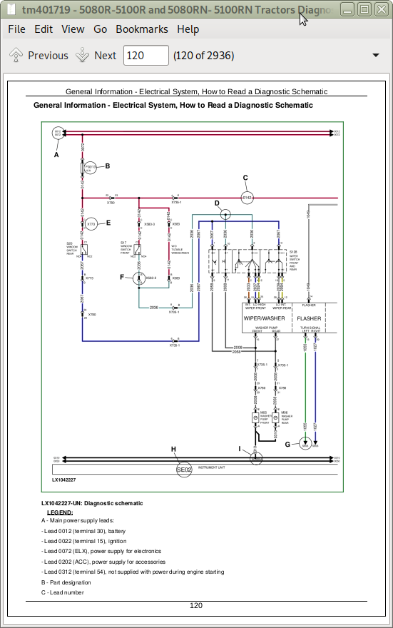
tm401719 - 5080R-5100R and 5080RN-5100RNTractorsDiagnostics
Table of Contents
Foreword
Section 210: General Information
Group 05: Safety
Safety Information
Recognize Safety Information
”Important” Information
”Note” Information
Prevent Machine Runaway
Handle Fluids Safely—Avoid Fires
Prevent Battery Explosions
Prepare for Emergencies
Prevent Acid Burns
Avoid High-Pressure Fluids
Service Cooling System Safely
Remove Paint Before Welding or Heating
Avoid Heating Near Pressurized Fluid Lines
Work In Ventilated Area
Wear Protective Clothing
Practice Safe Maintenance
Park Machine Safely
Use Proper Lifting Equipment
Construct Dealer-Made Tools Safely
Support Machine Properly
Work in Clean Area
Illuminate Work Area Safely
Service Machines Safely
Use Proper Tools
Service Tires Safely
Service Front-Wheel Drive Tractor Safely
Safety Information - Air Brake System
Avoid Eye Contact With Radar
Keep ROPS Installed Properly
Replace Safety Signs
Dispose of Waste Properly
Live With Safety
Safety Measures on Electronic Control Units
Safety Instructions for Replacing a Halogen Bulb
Safety Instructions for Replacing Xenon (HID) Bulbs and Ballast Units
Group 10: General References
General Information - General References, Summary of References
General Information - Transmission and Hydraulic System, Introductory Checks
General Information - Inch Bolt and Cap Screws, Torque Values
General Information - Metric Bolt and Cap Screws, Torque Values
General Information - Hydraulic System Inch Fittings, Torque Values
General Information - Hydraulic System Metric Fittings, Torque Values
General Information - Electrical System, Component Identification Table
General Information - Electrical System, How to Read a Diagnostic Schematic
General Information - Electrical System, Lead Numbers and Color Codes
General Information - Electrical System, Symbols in Schematic, Wiring and Harness Diagrams
General Information - Electrical System, Troubleshooting Unsolved Problems
General Information - Electrical System, Worksheet for Circuit/Harness Test
General Information - Electrical System, Approach to Tabular Diagnostic Procedures
General Information - Electrical System, Visual Check
General Information - Electrical System, Electrical Circuit Malfunctions
General Information - Electrical System, Seven-Step Test Procedure
General Information - Hydraulic System, Symbols in Circuit Diagrams
General Information - Country Version
Section 211: Diagnostic Trouble Codes
Group BCU: BCU Control Unit
BCU 000084.02 - B35 - Wheel Speed Sensor, Out of Range
BCU 000168.03 - Control Unit, Supply Voltage Too High
BCU 000168.04 - Control Unit, Supply Voltage Too Low
BCU 000168.16 - Control Unit, Supply Voltage Too High
BCU 000168.17 - Control Unit, Supply Voltage Too Low (Engine Speed Above 1500 rpm)
BCU 000168.18 - Control Unit, Supply Voltage Too Low (Engine Speed Above 500 rpm)
BCU 000177.18 - Transmission Oil Temperature Too Low During Calibration
BCU 000186.02 - B06 - Sensor for Rear PTO Speed, Open Circuit
BCU 000186.15 - B06 - Rear PTO Speed Sensor, Speed Present Despite Rear PTO Being Switched Off
BCU 000186.17 - B06 - Rear PTO Speed Sensor, Speed Not Present
BCU 000190.02 - B72 - Crankshaft Speed Sensor, Open Circuit
BCU 000237.02 - VIN Information, Mismatch
BCU 000237.14 - VIN Information, System Deactivated
BCU 000237.31 - VIN Information, Incorrect
BCU 000629.12 - Control Unit Internal Fault
BCU 000639.12 - Vehicle CAN BUS, High Error Rate
BCU 000639.14 - Vehicle CAN BUS, Very High Error Rate
BCU 000746.31 - Y05 - Differential Lock Solenoid Valve, Fault
BCU 000980.07 - S21 - Rear PTO Switch, Fault
BCU 001058.18 - INFORMATION FOR OPERATOR: Pressure Switch for Air-Brake System Is Not Activated (Pressure Too Low)
BCU 001504.14 - INFORMATION FOR OPERATOR: Operator Presence Switch Not Activated While HMS is Selected
BCU 001873.03 - B21 - Hitch Position Sensor, Voltage Too High
BCU 001873.04 - B21 - Hitch Position Sensor, Voltage Too Low
BCU 001873.15 - B21 - Hitch Position Sensor, Voltage Too High During Calibration
BCU 001873.17 - B21 - Hitch Position Sensor, Voltage Too Low During Calibration
BCU 001882.02 - B58 - Sensor for Front PTO Speed, Open Circuit
BCU 001882.15 - B58 - Front PTO Speed Sensor, Speed Present Despite Front PTO Being Switched Off
BCU 001882.17 - B58 - Front PTO Speed Sensor, Speed Not Present
BCU 001883.31 - Rear PTO Speed Too High
BCU 001890.03 - B179 - PTO Shaft Spline Identifier Switch, Supply Voltage Too High
BCU 001890.04 - B179 - PTO Shaft Spline Identifier Switch, Supply Voltage Too Low
BCU 001890.31 - B179 - PTO Shaft Spline Identifier Switch, Fault
BCU 001893.07 - S06 - Front PTO Switch, Fault
BCU 001894.31 - INFORMATION FOR OPERATOR: Rear PTO Switch was On When Engine was Started
BCU 002000.09 - Incorrect CAN BUS Message, Information from ECU
BCU 002003.09 - Incorrect CAN BUS Message, Information from EPC
BCU 002023.09 - Incorrect CAN BUS Message, Information from BIF
BCU 002818.31 - INFORMATION FOR OPERATOR: Operator Presence Switch Not Activated
BCU 002876.07 - S08 - Turn Signal Lever, Fault (Turn Signal)
BCU 303053.03 - B26 - Sensitivity Potentiometer, Signal Voltage Too High
BCU 303053.04 - B26 - Sensitivity Potentiometer, Signal Voltage Too Low
BCU 303056.03 - B27 - Raise-Limit Potentiometer, Signal Voltage Too High
BCU 303056.04 - B27 - Raise-Limit Potentiometer, Signal Voltage Too Low
BCU 303057.03 - B27 - Rate-of-Drop Potentiometer, Signal Voltage Too High
BCU 303057.04 - B27 - Rate-of-Drop Potentiometer, Signal Voltage Too Low
BCU 522507.31 - Control Unit Not Calibrated
BCU 523438.02 - Control Unit Internal Fault
BCU 523652.02 - Control Unit Connected to Wrong Harness Connector
BCU 523689.31 - S22 - Differential Lock Switch, Fault
BCU 523690.02 - S23/S68 - Switches for Remote Control of Hitch (Right/Left), Fault
BCU 523701.05 - M08 - Stepper Motor for Hitch (Coil 2), Open Circuit
BCU 523701.06 - M08 - Stepper Motor for Hitch (Coil 2), Current Too High
BCU 523702.14 - VIN Information, System De-Activated
BCU 523702.31 - VIN Information, Incorrect
BCU 523703.02 - B19 - Right Draft Sensor, Distorted Signal During Calibration
BCU 523703.03 - B19 - Right Draft Sensor, Voltage Too High During Calibration
BCU 523703.04 - B19 - Right Draft Sensor, Voltage Too Low During Calibration
BCU 523703.15 - B19 - Right Draft Sensor, Voltage Too High
BCU 523703.17 - B19 - Right Draft Sensor, Voltage Too Low
BCU 523704.02 - B20 - Left Draft Sensor, Distorted Signal During Calibration
BCU 523704.03 - B20 - Left Draft Sensor, Voltage Too High During Calibration
BCU 523704.04 - B20 - Left Draft Sensor, Voltage Too Low During Calibration
BCU 523704.15 - B20 - Left Draft Sensor, Voltage Too High
BCU 523704.17 - B20 - Left Draft Sensor, Voltage Too Low
BCU 523745.31 - S100 - HMS Program Switch, Fault
BCU 523751.05 - M08 - Stepper Motor for Hitch (Coil 1), Open Circuit
BCU 523751.06 - M08 - Stepper Motor for Hitch (Coil 1), Current Too High
BCU 523753.16 - M08 - Stepper Motor for Hitch, Raising Deadband Too High During Calibration
BCU 523753.18 - M08 - Stepper Motor for Hitch, Raising Deadband Too Low During Calibration
BCU 523756.16 - M08 - Stepper Motor for Hitch, Lowering Deadband Too High During Calibration
BCU 523756.18 - M08 - Stepper Motor for Hitch, Lowering Deadband Too Low During Calibration
BCU 523758.11 - S121 - Remote Control Switch for Rear PTO (Right), Fault
BCU 523759.11 - S44 - Remote Control Switch for Rear PTO (Left), Fault
BCU 523760.04 - Turn Signal/Hazard Flasher System, Supply Voltage Too Low
BCU 523760.31 - Turn Signal/Hazard Flasher System, Fault
BCU 523834.03 - B27 - Depth-Setting Potentiometer, Voltage Too High
BCU 523834.04 - B27 - Depth-Setting Potentiometer, Voltage Too Low
BCU 523839.14 - INFORMATION FOR OPERATOR: Park brake is engaged and a gear is selected
BCU 523839.31 - INFORMATION FOR OPERATOR: Park brake is engaged while wheel speed is detected
BCU 523843.02 - S24 - Quick Raise/Lower Switch, Switch Status Out of Range
BCU 523843.03 - S24 - Quick Raise/Lower Switch, Voltage Too High
BCU 523843.04 - S24 - Quick Raise/Lower Switch, Voltage Too Low
BCU 523904.31 - INFORMATION FOR OPERATOR: Operator Presence Switch Not Activated While Front PTO is Selected
BCU 523905.31 - Y01 - Front PTO Solenoid Valve, Fault
BCU 523908.14 - INFORMATION FOR OPERATOR: Remote Control Switch for Rear PTO is Activated
BCU 523908.31 - S45 - PTO Preselector Switch, Fault
BCU 524055.11 - Control Unit Internal Fault
BCU 524055.31 - Control Unit Not Calibrated
BCU 524216.02 - INFORMATION FOR OPERATOR: Switch Off the Front PTO Switch
BCU 524216.14 - INFORMATION FOR OPERATOR: Switch On the Front PTO Switch.
BCU 524216.31 - INFORMATION FOR OPERATOR: Front PTO was Switched On When Engine Was Started
BCU 524224.02 - INFORMATION FOR OPERATOR: Switch Off the Rear PTO Switch
BCU 524224.14 - INFORMATION FOR OPERATOR: Switch On the Rear PTO Switch.
BCU 524224.31 - INFORMATION FOR OPERATOR: Rear PTO was Switched On When Engine Was Started
BCU 524235.31 - Y03 - Front-Wheel Drive Solenoid Valve, Fault
BCU 524252.31 - Y04 - Solenoid Valve for Rear PTO, Fault
Group BIF: BIF Control Unit
BIF 000096.03 - B176 - Fuel Gauge Sensor, Voltage Too High
BIF 000096.04 - B176 - Fuel Gauge Sensor, Open Circuit
BIF 000096.17 - B176 - Fuel Gauge Sensor, Fuel Level Low
BIF 000100.00 - Engine Oil Pressure Low
BIF 000107.16 - B02 - Sensor for Engine Air Cleaner, Fault
BIF 000110.00 - Coolant Temperature Very High
BIF 000110.03 - B56 - Sensor for Coolant Temperature, Voltage Too High
BIF 000110.04 - B56 - Sensor for Coolant Temperature, Voltage Too Low
BIF 000110.16 - Coolant Temperature High
BIF 000126.15 - Dirty Transmission Oil Filter
BIF 000126.16 - Transmission Oil Filter Restricted
BIF 000127.00 - Transmission Oil Pressure Low
BIF 000167.16 - D+ Voltage High (Engine Running)
BIF 000167.17 - D+ Voltage Too Low (Engine Speed Over 1500 rpm)
BIF 000167.18 - D+ Voltage Too Low (Engine Speed up to 1500 rpm)
BIF 000168.16 - System Voltage Too High (Engine Running)
BIF 000168.17 - System Voltage Too Low (Engine Speed Over 1500 rpm)
BIF 000168.18 - System Voltage Too Low (Engine Speed up to 1500 rpm)
BIF 000177.00 - Transmission Oil Temperature Very High
BIF 000177.03 - B60 - Sensor for Transmission Oil Temperature, Voltage Too High
BIF 000177.04 - B60 - Sensor for Transmission Oil Temperature, Voltage Too Low
BIF 000177.16 - Transmission Oil Temperature High
BIF 000186.16 - INFORMATION FOR OPERATOR: Warning, Rear PTO Speed
BIF 000190.02 - No Signal From Engine Speed Sender
BIF 000628.02 - Control Unit, Internal Fault
BIF 000639.02 - CAN BUS, Open Circuit
BIF 301141.31 - INFORMATION FOR OPERATOR: Switch Off Worklights While Driving on Road
BIF 301143.31 - INFORMATION FOR OPERATOR: Preheat Time Remaining
Group ECU: ECU Control Unit
ECU 000028.03 - A19 - Cruise Control Potentiometer, Voltage Too High
ECU 000028.04 - A19 - Cruise Control Potentiometer, Voltage Too Low
ECU 000029.03 - B96 - Hand Throttle Potentiometer, Voltage Too High
ECU 000029.04 - B96 - Hand Throttle Potentiometer, Voltage Too Low
ECU 000091.03 - B79 - Accelerator Pedal Potentiometer, Voltage Too High
ECU 000091.04 - B79 - Accelerator Pedal Potentiometer, Voltage Too Low
ECU 000097.03 - Water-in-Fuel Sensor Signal Voltage Too High
ECU 000097.04 - Water-in-Fuel Sensor Signal Voltage Too Low
ECU 000097.16 - Water In Fuel Detected
ECU 000100.01 - Engine Oil Pressure Extremely Low
ECU 000100.31 - Engine Oil Pressure Invalid
ECU 000105.00 - Intake Air Temperature Extremely High
ECU 000105.03 - Intake Air Temperature Sensor Input Voltage Too High
ECU 000105.04 - Intake Air Temperature Sensor Input Voltage Too Low
ECU 000105.15 - Intake Air Temperature Slightly High
ECU 000105.16 - Intake Air Temperature Moderately High
ECU 000108.02 - Barometric Air Pressure Invalid
ECU 000110.00 - Engine Coolant Temperature Extremely High
ECU 000110.03 - Engine Coolant Temperature Sensor Input Voltage Too High
ECU 000110.04 - Engine Coolant Temperature Sensor Input Voltage Too Low
ECU 000110.15 - Engine Coolant Temperature Slightly High
ECU 000110.16 - Engine Coolant Temperature Moderately High
ECU 000157.03 - Fuel Rail Pressure Sensor Input Voltage Too High
ECU 000157.04 - Fuel Rail Pressure Sensor Input Voltage Too Low
ECU 000157.10 - Fuel Rail Pressure Loss Detected
ECU 000157.17 - Fuel Rail Pressure Not Developed
ECU 000158.17 - ECU Power Down Error
ECU 000174.00 - Fuel Temperature Extremely High
ECU 000174.03 - Fuel Temperature Sensor Input Voltage Too High
ECU 000174.04 - Fuel Temperature Sensor Input Voltage Too Low
ECU 000174.16 - Fuel Temperature Moderately High
ECU 000189.00 - Engine Speed Derate
ECU 000190.00 - Engine Overspeed Extreme
ECU 000190.16 - Engine Overspeed Moderate
ECU 000237.02 - VIN Information, Mismatch
ECU 000237.13 - VIN Information, Option Code Invalid
ECU 000237.31 - VIN Information, Incorrect
ECU 000611.03 - Electronic Injector Wiring Shorted To Power Source
ECU 000611.04 - Electronic Injector Wiring Shorted To Ground
ECU 000627.01 - High Resistance In All Injector Circuits
ECU 000629.12 - ECU Error (EEPROM)
ECU 000629.13 - ECU Error
ECU 000636.02 - Pump Position Sensor Input Noise
ECU 000636.05 - Pump Position Sensor Current Too Low
ECU 000636.06 - Pump Position Sensor Current Too High
ECU 000636.08 - Pump Position Sensor Input Missing
ECU 000636.10 - Pump Position Sensor Input Pattern Error
ECU 000637.02 - Crankshaft Speed Sensor Input Noise
ECU 000637.05 - Crankshaft Speed Sensor Current Too Low
ECU 000637.06 - Crankshaft Speed Sensor Current Too High
ECU 000637.07 - Crank Position/Pump Position Timing Moderately Out of Sync
ECU 000637.08 - Crankshaft Speed Sensor Signal Input Missing
ECU 000637.10 - Crankshaft Speed Sensor Input Pattern Error
ECU 000647.05 - M32 - Intercooler Fan, Open Circuit
ECU 000647.31 - S154 - Intercooler Purge Switch, Fault
ECU 000651.02 - Cylinder No. 1 Electronic Injector Part Number Invalid
ECU 000651.05 - Cylinder No. 1 Electronic Injector Circuit Open
ECU 000651.06 - Cylinder No. 1 Electronic Injector Circuit Shorted
ECU 000651.13 - Calibration Fault, Cylinder No. 1 Injector
ECU 000652.02 - Cylinder No. 2 Electronic Injector Part Number Invalid
ECU 000652.05 - Cylinder No. 2 Electronic Injector Circuit Open
ECU 000652.06 - Cylinder No. 2 Electronic Injector Circuit Shorted
ECU 000652.13 - Calibration Fault, Cylinder No. 2 Injector
ECU 000653.02 - Cylinder No. 3 Electronic Injector Part Number Invalid
ECU 000653.05 - Cylinder No. 3 Electronic Injector Circuit Open
ECU 000653.06 - Cylinder No. 3 Electronic Injector Circuit Shorted
ECU 000653.13 - Calibration Fault, Cylinder No. 3 Injector
ECU 000654.02 - Cylinder No. 4 Electronic Injector Part Number Invalid
ECU 000654.05 - Cylinder No. 4 Electronic Injector Circuit Open
ECU 000654.06 - Cylinder No. 4 Electronic Injector Circuit Shorted
ECU 000654.13 - Calibration Fault, Cylinder No. 4 Injector
ECU 000676.03 - Glow Plug Relay, Voltage Too High
ECU 000676.05 - Glow Plug Relay Voltage Too Low
ECU 001347.03 - Suction Control Valve Current Too High
ECU 001347.05 - Suction Control Valve Current Mismatch
ECU 001347.07 - Fuel Rail Pressure Control Error
ECU 001569.31 - Fuel Derate
ECU 001639.01 - M32 - Intercooler Fan, Speed to Low
ECU 001639.16 - M32 - Intercooler Fan, Speed to High
ECU 002033.09 - Incorrect CAN BUS Message, CAN Message from BCU
ECU 002033.14 - Communication Problem between ECU and BCU
ECU 002033.19 - Communication Problem between ECU and BCU
ECU 003509.03 - Sensor Supply Voltage 1 Too High
ECU 003509.04 - Sensor Supply Voltage 1 Too Low
ECU 003510.03 - Sensor Supply Voltage 2 Too High
ECU 003510.04 - Sensor Supply Voltage 2 Too Low
ECU 003511.03 - Sensor Supply Voltage 3 Too High
ECU 003511.04 - Sensor Supply Voltage 3 Too Low
Group EPC: EPC Control Unit
EPC 000084.07 - Wheel Speed Detected During Calibration of Transmission
EPC 000084.14 - B35 - Wheel Speed Sensor, Fault
EPC 000084.19 - Incorrect CAN BUS Message, Wheel Speed from BCU
EPC 000091.07 - Incorrect CAN BUS Message, Accelerator Pedal Position from ECU
EPC 000091.19 - Incorrect CAN BUS Message, Engine Speed from ECU
EPC 000092.19 - Incorrect CAN BUS Message, Engine Load from ECU
EPC 000126.16 - Transmission Oil Filter Restricted
EPC 000127.01 - Transmission Oil Pressure Too Low
EPC 000158.04 - Control Unit, Supply Voltage Too Low
EPC 000177.00 - Transmission Oil Temperature Very High
EPC 000177.16 - Transmission Oil Temperature High
EPC 000190.08 - Engine Speed Signal Incorrect
EPC 000190.19 - Incorrect CAN BUS Message, Engine Speed from ECU
EPC 000191.00 - Transmission Speed During Calibration Too High
EPC 000191.17 - Transmission Speed Too Low
EPC 000237.02 - VIN Information, Mismatch
EPC 000237.14 - VIN Information, System Deactivated
EPC 000237.31 - VIN Information, Incorrect
EPC 000598.02 - S72 - Clutch Pedal Switch, Fault
EPC 000628.02 - Control Unit Internal Fault
EPC 000628.12 - Control Unit Internal Fault
EPC 000628.13 - Control Unit Internal Fault
EPC 000629.12 - Control Unit Internal Fault
EPC 000630.14 - Incorrect Calibration Value
EPC 000639.12 - Power Train CAN BUS, High Error Rate
EPC 000734.05 - Y33 - Forward Solenoid Valve, Current Too Low
EPC 000735.05 - Y36 - Reverse Solenoid Valve, Current Too Low
EPC 000736.05 - Y40 - Gear Selector Solenoid Valve K1, Current Too Low
EPC 000737.05 - Y39 - Gear Selector Solenoid Valve K2, Current Too Low
EPC 001079.02 - 5-volt Power Supply, Fault
EPC 001079.03 - 5-volt Power Supply, Voltage Too High
EPC 001079.04 - 5-volt Power Supply, Voltage Too Low
EPC 001666.03 - S158 - Auto-Mode Switch, Voltage Too High
EPC 002000.09 - Incorrect CAN BUS Message, Information from ECU
EPC 002033.09 - Incorrect CAN BUS Message, Information from BCU
EPC 002408.19 - Incorrect CAN BUS Message, Rear PTO Engagement from BCU
EPC 522506.04 - A68 - Reverse Drive Lever, Neutral Switch Opened by Mistake
EPC 522506.31 - INFORMATION FOR OPERATOR: Neutral Switch Closed During Start-Up
EPC 523652.02 - Control Unit Connected to Wrong Harness Connector
EPC 523677.02 - S158 - Declutch Switch on Range Shift Lever Faulty
EPC 523677.03 - S158 - Declutch Switch on Range Shift Lever, Signal Voltage too High
EPC 523677.04 - S158 - Declutch Switch on Range Shift Lever, Signal Voltage too Low
EPC 523677.07 - S158 - Declutch Switch on Range Shift Lever, Voltage Too High During Start-Up
EPC 523677.14 - INFORMATION FOR OPERATOR: Declutch Switch on Range Shift Lever Deactivated
EPC 523677.31 - S158 - Declutch Switch on Range Shift Lever Deactivated, No Operator Present
EPC 523961.07 - INFORMATION FOR OPERATOR: Reverse Drive Lever Not in Neutral Position while Park Lock is Engaged
EPC 523966.31 - INFORMATION FOR OPERATOR: Come-Home Mode Activated
EPC 523969.11 - S158 - Gear Selector Switch, Voltage Too High During Start-Up
EPC 524020.31 - INFORMATION FOR OPERATOR: Reverse Drive Lever Not in Neutral Position During Start-Up
EPC 524023.31 - A68 - Reverse Drive Lever, Forward Switch or Reverse Switch Closed, But Not-Neutral Switch Open
EPC 524024.31 - A68 - Reverse Drive Lever, Forward and Reverse Switches Actuated At Same Time
EPC 524025.31 - A68 - Reverse Drive Lever, Forward Switch or Reverse Switch Open, But Not-Neutral Switch Closed
EPC 524173.02 - B65 - Clutch Pedal Potentiometer, Voltages at Channel 1 and Channel 2 not in the Correct Ratio
EPC 524173.03 - B65 - Clutch Pedal Potentiometer, Voltage at Channel 1 Too High
EPC 524173.04 - B65 - Clutch Pedal Potentiometer, Voltage at Channel 1 Too Low
EPC 524173.07 - Clutch Pedal Depressed While There is a Fault at the Clutch Pedal Switch
EPC 524230.03 - Y38 - Proportional Solenoid Valve for Transmission Enable Stuck in Open Position
EPC 524230.04 - Y38 - Proportional Solenoid Valve for Transmission Enable Stuck in Closed Position
EPC 524230.05 - Y38 - Proportional Solenoid Valve for Transmission Enable, Fault
EPC 524234.03 - B105 - Sensor for Enable Pressure, Voltage Too High
EPC 524234.04 - B105 - Sensor for Enable Pressure, Voltage Too Low
Group PRF: PRF Control Unit
PRF 000629.12 - Control Unit, Internal Fault
PRF 000639.12 - Vehicle CAN BUS, High Error Rate
PRF 000639.13 - CAN BUS not detected
PRF 000639.14 - CAN BUS, Very High Error Rate
PRF 002808.03 - Key error
Section 212: Observable Symptoms
Group 40: Electronics
Control Unit(s) Not Displayed
Problems with the CAN-BUS Connection to Service ADVISOR
Problems when Programming Control Units (BIF, BCU, EPC or ECU)
Problems with the Starting Motor Circuit
Problems with the Charging Circuit
Problems with the Horn
Problems with the Cigarette Lighter
Problems with the Operator's Seat
Problems with the Parking Lights
Problems with Low-Beam Headlights (without H4 Farm Headlights on the Cab Frame)
Problems with High-Beam Headlights (without H4 Farm Headlights on the Cab Frame)
Problems with Low-Beam Headlights (with H4 Farm Headlights on the Cab Frame)
Problems with High-Beam Headlights (with H4 Farm Headlights on the Cab Frame)
Problems with the Worklights on Front of Roof
Problems with the Worklights on Rear of Roof
Problems with the Front Corner Worklights
Problems with the Worklights on Cab Frame
Problems with the Brake Pedal Sensor Unit
Problems with the Differential Lock
Problems with the Front Loader (X37-1)
Problems with the Accessories (X37-3)
Problems with the Radio
Problem with the Air-Conditioning System - Problem with the Fan
Problem with the Windshield Wiper and Washer
Problem with the Rear Window Wiper and Washer
Problems with the Beacon Light
Problems with the Rear PTO
Problem with Backup Alarm
Group 45: Electronic Control Units
Problems when Programming the BCU Control Unit
Problems when Programming the ECU Control Unit
Problems when Programming the EPC Control Unit
Problem with the BCU Control Unit
Problem with the BIF Control Unit
Problem with the ECU Control Unit
Problem with the EPC Control Unit
Problem with the PRF Control Unit
Group 55: PowrQuad and PowrQuad Plus Transmissions
Problem with PowrQuad Plus and AutoQuad Transmissions
Group 56: Drive Systems
Problem with the Front-Wheel Drive
Problem with the Rear PTO
Problem with the Differential Lock
Problem with the Front PTO
Group 60: Steering and Brakes
Problems with the Brakes
Problems with the Steering
Problems with the Park Brake
Problems with the Hydraulic Trailer Brake
Problems with the Air Brake System
Group 70: Hydraulic system
Problem with the Hitch
Problems with the Remote Control of Hitch
Problem with the PC Hydraulic System
Problem with Selective Control Valves
Group 80: Miscellaneous
Problem with Noises when Driving with Front-Wheel Drive Engaged
Problem with Unusual Vibration when Driving with Front-Wheel Drive Engaged
Problem with the Front Hitch
Group 90: Operator's Cab
Operator's Cab - Summary of References
Problem with the Air-Conditioning System - Poor Cooling Effect
Problem with the Air-Conditioning System - Icing at Evaporator, Expansion Valve, Receiver-Drier or Pressure Lines (Liquid)
Problem with the Air-Conditioning System - Unusual Noises During Operation
Problem with the Air-Conditioning System - No Cooling Effect
Problem with the Fan - Poor Air Flow
Problem with the Fan - Fan Does Not Turn On
Problem with the Fan - Fan Operates in Stage 4 Only
Problem with the Fan - Unusual Noises During Operation
Problem with the Air Comfort Seat
Section 213: System Diagnostics
Group 45: Electronics
System Diagnostics for Electronics - Summary of References
Check for CAN BUS
VIN Security Fault Diagnosis
Check System Voltage
Check BCU Supply Voltage
Check BIF Supply Voltage
Check ECU Supply Voltage
Check EPC Supply Voltage
Check PRF Supply Voltage
Group 55: PowrQuad Transmission
Preliminary Test on Shift Elements and Vehicle Clutch/Brake in Off-Load Condition
Group 70: Hydraulic system
Hitch Control Check
Section 220: Engine
Group 05: General Information
Information on Engine
Group 10: Operational Checks
Engine - Operational Checks, Summary of References
Engine - Safety Measures
Engine - Preliminary Engine Tests
Group 15: Tests and Adjustments
Engine - Tests and Adjustments, Summary of References
Engine - Measuring Engine Power
Engine - Measuring PTO Power Output
Section 230: Fuel, Air Intake and Cooling Systems
Group 15: Tests and Adjustments
Fuel, Air Intake and Cooling Systems - Tests and Adjustments, Summary of References
Fuel, Air Intake and Cooling Systems - General Information
Fuel, Air Intake and Cooling Systems - Explanation of Checks
Fuel, Air Intake and Cooling Systems - Safety Measures
Fuel, Air Intake and Cooling Systems - Special Tools, Summary of References
Fuel, Air Intake and Cooling Systems - Specifications
Air Intake System - Check Charge Pressure
Air Intake System - Check Sensor (B02) for Engine Air Cleaner
Cooling System - Fill/Bleed the System
Cooling System - Leak Test
Cooling System - Test Thermostat Opening Temperature
Cooling System - Check Viscous Fan Drive
Fuel System - Check Fuel Transfer Pump
Group 20A: Fuel System
Fuel System, Summary of References
Fuel System - Theory of Operation
Fuel System - Fuel Cooler, Component Information
Group 20B: Air Intake System
Air Intake System, Summary of References
Air Intake System - Theory of Operation
Group 20C: Cooling System
Cooling System, Summary of References
Cooling System - Coolant Circuit, Description
Cooling System - Radiator Description, Component Information
Cooling System - Intercooler, Component Information
Cooling System - Transmission Oil Cooler, Component Information
Cooling System - Viscous Fan Drive, Theory of Operation
Cooling System - Automatic Drive Belt Tensioner, Theory of Operation
Group 20D: Cold Start Aids
Cold Start Aids, Summary of References
Cold-Weather Starting Aids - General Information
Cold Start Aids - Fuel Preheater, Component Information
Cold Start Aids - Electrical Starting Aid, Component Information
Cold Start Aids - Coolant Preheater, Component Information
Cold Start Aids - Transmission Oil Preheater, Component Information
Section 240: Electrical System
Group SE01: Starting Motor and Charging Circuit
SE01 - Starting Motor and Charging Circuit - Summary of References
Diagnostic Schematic, SE01 - Starting Motor and Charging Circuit
Group SE01A: Fuel Preheater
SE01A - Fuel Preheater - Summary of References
Diagnostic Schematic, SE01A - Fuel Preheater
M31 - Fuel Pump, Circuit/Harness Test
R02 - Heating Element of Fuel Preheater, Circuit/Harness Test
Group SE01B: Electrical Starting Aid
SE01B - Electrical Starting Aid - Summary of References
Diagnostic Schematic, SE01B - Electrical Starting Aid
K05PLB - Relay for Electrical Starting Aid, Circuit/Harness Test
R15 - Heating Element for Electrical Starting Aid, Circuit/Harness Test
Group SE02: BIF Control Unit (Basic Informator)
SE02 - BIF Control Unit (Basic Informator) - Summary of References
Diagnostic Schematic, SE02 - BIF Control Unit (Basic Informator)
Test Procedure in the Event of Occasional Malfunctions in the BIF Circuits (BIF Beep Mode)
B02 - Sensor for Engine Air Cleaner, Circuit/Harness Test
B07 - Pressure Switch for Transmission Oil Filter, Circuit/Harness Test
B31 - Pressure Switch for Transmission Oil, Circuit/Harness Test
B60 - Sensor for Transmission Oil Temperature, Circuit/Harness Test
B176 - Fuel Level Sensor, Circuit/Harness Test
S32 - Roll-Mode Switch, Circuit/Harness Test
Group SE03: Horn
SE03 - Horn - Summary of References
Diagnostic Schematic, SE03 - Horn
Horn, Circuit/Harness Test
Group SE04: Operator's Seat and Cigarette Lighter
SE04 - Operator's Seat and Cigarette Lighter - Summary of References
Diagnostic Schematic, SE04 - Operator's Seat and Cigarette Lighter
A29 - Operator's Seat with Compressor and Heater, Circuit/Harness Test
E05 - Cigarette Lighter, Circuit/Harness Test
Group SE06: Lights
SE06 - Lights - Summary of References
Diagnostic Schematic, SE06 - Lights
E01 - R.H. Headlight, Circuit/Harness Test
E02 - L.H. Headlight, Circuit/Harness Test
E03 - L.H. Clearance Light, Circuit/Harness Test
E04 - R.H. Clearance Light, Circuit/Harness Test
E07 - Left Headlight on Cab Frame, Circuit/Harness Test
E08 - Right Headlight on Cab Frame, Circuit/Harness Test
E13 - L.H. Tail Light, Circuit/Harness Test
E14 - R.H. Tail Light, Circuit/Harness Test
E20-L - Left Worklight on Cab Frame, Circuit/Harness Test
E20-R - Right Worklight on Cab Frame, Circuit/Harness Test
E21/1 - R.H. License Plate Light, Circuit/Harness Test
E21/2 - L.H. License Plate Light, Circuit/Harness Test
S09 - Light Switch, Circuit/Harness Test
S10 - High-Beam Switch, Circuit/Harness Test
S11 - Switch for Worklights on Cab Frame, Circuit/Harness Test
S30 - Headlight Flasher Switch, Circuit/Harness Test
Group SE07: Worklights
SE07 - Worklights - Summary of References
Diagnostic Schematic, SE07 - Worklights
E09 - Front Corner Worklights, Circuit/Harness Test
E11 - Worklights at Rear of Roof, Circuit/Harness Test
E18 - Worklights at Front of Roof, Circuit/Harness Test
S59 - Switch for Front Corner Worklights, Circuit/Harness Test
S92/1 - Switch for Worklights at Front of Roof, Circuit/Harness Test
S92/2 - Switch for Worklights at Rear of Roof, Circuit/Harness Test
Group SE08: Connector for Accessories
SE08 - Connector for Accessories - Summary of References
Diagnostic Schematic, SE08 - Connector for Accessories
Group SE09: Radio, Dome Light and Console Light
SE09 - Radio, Dome Light and Console Light - Summary of References
Diagnostic Schematic, SE09 - Radio, Dome Light and Console Light
E30 - Console Light, Circuit/Harness Test
E32 - Light for Air-Brake Pressure Gauge, Circuit/Harness Test
Group SE10: Air Conditioning and Fan
SE10 - Air Conditioning and Fan - Summary of References
Diagnostic Schematic, SE10 - Air Conditioning and Fan
Group SE11: Windshield Wiper and Washer
SE11 - Windshield Wiper and Washer - Summary of References
Diagnostic Schematic, SE11 - Windshield Wiper and Washer
Windshield Wiper, Circuit/Harness Test
Windshield Washer, Circuit/Harness Test
Group SE12: Rear Window Wiper and Washer
SE12 - Rear Window Wiper and Washer - Summary of References
Diagnostic Schematic, SE12 - Rear Window Wiper and Washer
Rear Window Wiper, Circuit/Harness Test
Rear Window Washer, Circuit/Harness Test
Group SE13: Beacon Light
SE13 - Beacon Light - Summary of References
Diagnostic Schematic, SE13 - Beacon Light
Beacon Light, Circuit/Harness Test
Group SE14B: 3-Terminal and 7-Terminal Power Outlet Sockets (ECE)
SE14B - 3-Terminal and 7-Terminal Power Outlet Sockets (ECE) - Summary of References
Diagnostic Schematic, SE14B - 3-Terminal and 7-Terminal Power Outlet Sockets (ECE)
Group SE15: BCU Control Unit (Electronic Hitch Control)
SE15 - BCU Control Unit (Electronic Hitch Control) - Summary of References
Diagnostic Schematic, SE15 - BCU Control Unit (Electronic Hitch Control)
B19 - Right Draft Sensor, Circuit/Harness Test
B20 - Left Draft Sensor, Circuit/Harness Test
B21 - Sensor for Hitch Position, Circuit/Harness Test
B26 - Sensitivity Potentiometer, Circuit/Harness Test
B27 - Position Feedback Unit, Circuit/Harness Test
M08 - Stepper Motor for Hitch, Circuit/Harness Test
S23 - Switch for Hitch Remote Control (Right), Circuit/Harness Test
S24 - Quick Raise/Lower Switch, Circuit/Harness Test
S68 - Switch for Hitch Remote Control (Left), Circuit/Harness Test
Group SE16: BCU Control Unit (Basic Functions)
SE16 - BCU Control Unit (Basic Functions) - Summary of References
Diagnostic Schematic, SE16 - BCU Control Unit (Basic Functions)
Test Procedure in the Event of Occasional Malfunctions in the BCU Circuits (BCU Beep Mode)
B06 - Sensor for Rear PTO Speed, Circuit/Harness Test
B35 - Wheel Speed Sensor, Circuit/Harness Test
B37 - Switch for Park Brake Indicator Light, Circuit/Harness Test
B39 - Travel Speed Sensor (Radar), Circuit/Harness Test
B58 - Sensor for Front PTO Speed, Circuit/Harness Test
B112 - Brake Pedal Sensor Unit, Circuit/Harness Test
H34, H35, H42 and H43 Turn Signal Lights, Circuit/Harness Test
S05 - Front-Wheel Drive Switch with HMS, Circuit/Harness Test
S06 - Front PTO Switch, Circuit/Harness Test
S08 - Turn-Signal Lever, Circuit/Harness Test
S21 - Rear PTO Switch, Circuit/Harness Test
S22 - Differential Lock Switch, Circuit/Harness Test
S40 - Operator Presence Switch, Circuit/Harness Test
S43 - HMS Switch (On/Off), Circuit/Harness Test
S44 - Remote Control Switch for Rear PTO (Left), Circuit/Harness Test
S45 - PTO Preselector Switch, Circuit/Harness Test
S62 - Hazard Warning Light Switch, Circuit/Harness Test
S63 - Front-Wheel Drive Switch, Circuit/Harness Test
S95 - HMS Switch (Record/Save), Circuit/Harness Test
S100 - HMS Program Selector Switch, Circuit/Harness Test
S121 - Remote Control Switch for Rear PTO (Right), Circuit/Harness Test
Y01 - Solenoid Valve for Front PTO, Circuit/Harness Test
Y03 - Solenoid Valve for Front-Wheel Drive, Circuit/Harness Test
Y04 - Solenoid Valve for Rear PTO, Circuit/Harness Test
Y05 - Solenoid Valve for Differential Lock, Circuit/Harness Test
Group SE17: Signal Socket and Service Socket
SE17 - Signal Socket and Service Socket - Summary of References
Diagnostic Schematic, SE17 - Signal Socket and Service Socket
Group SE18: PRF Control Unit (Performance Monitor)
SE18 - PRF Control Unit (Performance Monitor) - Summary of References
Diagnostic Schematic, SE18 - PRF Control Unit (Performance Monitor)
Group SE22: CAN BUS Terminating Resistor
SE22 - CAN BUS Terminating Resistor - Summary of References
Diagnostic Schematic, SE22 - CAN BUS Terminating Resistor
Group SE23: Level 16 ECU Control Unit (Electronic Engine Control) for 2-Valve Engine with HPCR
SE23 - Level 16 ECU Control Unit (Electronic Engine Control) for 2-Valve HPCR Engine - Summary of References
Diagnostic Schematic, SE23 - Level 16 ECU Control Unit (Electronic Engine Control) for 2-Valve Engine with HPCR
A19 - Cruise Control Potentiometer, Circuit/Harness Test
B04 - Engine Oil Pressure Switch, Circuit/Harness Test
B79 - Accelerator Pedal Potentiometer, Circuit/Harness Test
B96 - Hand Throttle Potentiometer, Circuit/Harness Test
K05PLB - Relay for Electrical Starting Aid, Circuit/Harness Test
M32 - Intercooler Fan, Circuit/Harness Test
S154 - Intercooler Purge Switch, Circuit/Harness Test
Group SE25: Backup Alarm
SE25 - Backup Alarm - Summary of References
Diagnostic Schematic, SE25 - Backup Alarm
Backup Alarm, Circuit/Harness Test
Group SE26: EPC (Transmission Control with PowrQuad Plus or AutoQuad Plus Transmission)
SE26 - EPC Control Unit (Transmission Control with PowrQuad Plus or AutoQuad Plus Transmission) - Summary of References
Diagnostic Schematic, SE26 - EPC Control Unit (Transmission Control with PowrQuad Plus or AutoQuad Plus Transmission)
Test Procedure in the Event of Occasional Malfunctions in the EPC Circuits (EPC Beep Mode)
A68 - Reverse Drive Lever, Forward or Reverse Switch, Circuit/Harness Test
B65 - Clutch Pedal Potentiometer, Circuit/Harness Test
B104 - Sensor for Transmission Speed, Circuit/Harness Test
B105 - Enable Pressure Sensor, Circuit/Harness Test
B144 - Auto Mode Potentiometer, Circuit/Harness Test
S72 - Clutch Pedal Switch, Circuit/Harness Test
S114 - Park Lock Switch, Circuit/Harness Test
S158 - Switch for Gear Selector, Auto Mode and Clutch, Circuit/Harness Test
Y33 - Forward Solenoid Valve, Circuit/Harness Test
Y36 - Reverse Solenoid Valve, Circuit/Harness Test
Y38 - Proportional Solenoid Valve for Transmission Enable, Circuit/Harness Test
Y39 - Gear Selector Solenoid Valve K2, Circuit/Harness Test
Y40 - Gear Selector Solenoid Valve K1, Circuit/Harness Test
5-volt Supply Voltage, Circuit/Harness Test
Group SE32: Prewiring for GreenStar
SE32 - Prewiring for GreenStar - Summary of References
Diagnostic Schematic, SE32 - Prewiring for GreenStar
Group 105A: Component Information - Connectors and Contacts
B28-LH - Dome Light Switch, Left Door
F01PLB - Fuses (Fuse Box in Engine Compartment)
F02PLB - Fuses (Fuse Box in Engine Compartment)
F03PLB - Fuses (Fuse Box in Engine Compartment)
F04PLB - Fuses (Fuse Box in Engine Compartment)
F02 - Fuses (Fuse Box in Cab)
F03 - Fuses (Fuse Box in Cab)
F04 - Fuses (Fuse Box in Cab)
F05 - Fuses (Fuse Box in Cab)
F01FRM - Fuses (Fuse Box in Cab)
F27 - Fuse for Battery Voltage (with Battery Cut-Off Switch)
G02-1 - Terminal with Ring for Alternator
K01PLB - Starting Motor Relay
K05PLB - Relays (Fuse Box in Engine Compartment)
K06PLB - Relays (Fuse Box in Engine Compartment)
K01 - Relays (Fuse Box in Cab)
K06 - Relays (Fuse Box in Cab)
K07 - Relays/Diodes (Fuse Box in Cab)
K08 - Relays (Fuse Box in Cab)
K26 - Intermittent Wipe Relay for Windshield Wiper
K56 - Connection for Battery Cut-Off Relay
K57 - Connector of Relay for Battery Cut-Off Switch
M01-50 - Terminal for Starting Motor
S01F - Connector of Main (Key) Switch
S01F-1 - Connector of Main (Key) Switch
S09F - Connector of Light Switch
S32 - Roll-Mode Switch
S72 - Clutch Pedal Switch
Group 105B: Component Information - Connectors (X001 to X249)
X02F - Connecting Point between Harnesses W51 and W79
X02M - Connecting Point between Harnesses W79 and W51
X05F - Connector of 7-Terminal Power Outlet Socket (ECE) at Rear
X06F - Connector of 3-Terminal Power Outlet Socket (ECE)
X14M-1 - Connector of Hitch Control Position Feedback Unit
X14F-2 - Connector of Potentiometer for Hitch Control Sensitivity
X20F - Connecting Point between Harnesses W21 and W102
X20M - Connecting Point between Harnesses W102 and W21
X25F - Connector for Basic Informator (BIF) (Right)
X26F - Connector for Basic Informator (BIF) (Left)
X28F - Connector of Air-Conditioning Pressure Switch
X30 - Prewiring or Connector of Ground Speed Sensor (Radar)
X34F - Connector of Switch for Remote Control of Hitch (Right)
X35F - Connector of Switch for Remote Control of Hitch (Left)
X37F - Connector for Front Loader or Connecting Point between Harnesses W21 and W99
X37M - Connecting Point between Harnesses W99 and W21
X37F-1 - Connector of Front Loader
X37F-3 - Connector for Accessories
X38F - Connector of Windshield Wiper Motor
X39F - Connecting Point between Harnesses W21 and W102
X39M - Connecting Point between Harnesses W102 and W21
X39F - Connecting Point between Harnesses W23 and W91
X39M - Connecting Point between Harnesses W91 and W23
X43F - Connector of Rear Window Wiper Motor
X44F - Connector of Rear Window Washer Pump
X45F - Connector of Switch for Air-Conditioning Compressor
X46F - Connector of Fan Motor
X47F - Connector of Fan Motor
X48F - Connector of Fan Resistors
X63F - Connector of Windshield Washer Switch
X64F - Connector of Windshield Washer Switch
X66F - Connector of Horn
X67F - Connector of Right Headlight
X68F - Connector of Left Headlight
X69F-1 - Connector of Left Front Corner Worklight
X69F-2 - Connector of Right Front Corner Worklight
X70F - Connector of Air Cleaner Restriction Sensor
X72F - Connector of Thermostat Switch
X75M - Connector of Front-Wheel Drive Switch
X78F - Connector of Engine Oil Pressure Switch
X79F - Connector of Heating Element of Fuel Preheater
X80M - Connector of Transmission Oil Filter Pressure Switch
X83M - Connector of Transmission Oil Pressure Switch
X87F - Connector of Differential Lock Solenoid Valve
X88F-3 - Connector of Wheel Speed Sensor
X89F - Connector of Left Draft Sensor
X90F - Connector of Right Draft Sensor
X91F - Connector of Front-Wheel Drive Solenoid Valve
X92F - Connector of Stepper Motor for Hitch
X94F - Connector of Rear PTO Speed Sensor
X95F - Connector of Rear PTO Solenoid Valve
X96F - Connector of Hitch Position Sensor
X99F - Connector of Beacon Light Switch
X100F - Connector of Fan Switch
X101M - Connector of Switch for Worklights or Headlights on Cab Frame
X106F - Connector of Right Tail, Brake and Turn Signal Lights
X107F - Connector of Left Tail, Brake and Turn Signal Lights
X108F - Connector of Right Turn Signal and Clearance Lights
X109F - Connector of Left Turn Signal and Clearance Lights
X110F - Connector of Left Headlight or Left Worklight on Cab Frame
X111F - Connector of Left Headlight on Cab Frame
X113F - Connecting Point between Harnesses W23 and W17
X113M - Connecting Point between Harnesses W17 and W23
X113-1F - Connector of Left License Plate Light
X113-2F - Connector of Right License Plate Light
X114-1F1 - Connector of Inner Worklight on Rear of Roof (Right)
X114-1F2 - Connector of Outer Worklight on Rear of Roof (Right)
X114-2F1 - Connector of Inner Worklight on Rear of Roof (Left)
X114-2F2 - Connector of Outer Worklight on Rear of Roof (Left)
X115F - Connector of Right Headlight or Right Worklight on Cab Frame
X116F - Connector of Right Headlight on Cab Frame
X120-1F - Connector of Light for Air-Brake Pressure Gauge
X122F-2 - Connector of Differential Lock Switch
X125M - Connector of Rear PTO Switch
X126M - Connector of Hazard Warning Lights
X127M - Connector of Front PTO Switch
X128F-1 - Connector of Cigarette Lighter
X130F - Connector of A/C Compressor Clutch
X132F - Signal Socket
X142-1 - Prewiring for Beacon Light
X142-2 - Terminal with Ring for Beacon Light Ground Connection
X155F - Connector of Right Worklight or Right Headlight on Cab Frame
X156F - Connector of Left Worklight or Left Headlight on Cab Frame
X158M-1 - Connector of Radio Antenna Ground Connection
X167F - Connector of Front PTO Speed Sensor
X174F - Connector of Switch for Remote Control of Rear PTO (Left)
X178F-1 - Connecting Point between Harnesses W100 and W99
X178M-1 - Connecting Point between Harnesses W99 and W100
X178F-2 - Connector, Not Used
X185F - Connector of Backup Alarm Horn
X186F - Connector of Backup Alarm Switch
X187M - Connector of Backup Alarm Pressure Switch
X230F - Connector of Operator Presence Switch
X234F - Connecting Point between Harnesses W07 and W63
X234M - Connecting Point between Harnesses W63 and W07
X235F - Connector of Switch for Park Brake Indicator Light
X236M - Connector of Cruise Control Potentiometer
X239F - Connecting Point between Harnesses W21 and W04 or W05
X239M - Connecting Point between Harnesses W04 and W21
X239M - Connecting Point between Harnesses W05 and W21
X239F-1 - Connecting Point between Harnesses W05 and W04
X239F-2 - Connecting Point between Harnesses W05 and W06
X239M-2 - Connecting Point between Harnesses W06 and W05
X242M - Connector of HMS Switch (On/Off)
X243F - Connector for Rear PTO Preselector Switch
X247F - Connector of Display Module
Group 105C: Component Information - Connectors (X250 to X499)
X261F - Connector of Coolant Temperature Sensor
X278F - Connector of Windshield Wiper Switch
X280F - Connector of Backup Alarm Relay
X283F - Connector of Left Speaker
X284F - Connector of Right Speaker
X285F - Connector of Windshield Washer Pump
X301F - Connector of Intake Air Temperature Sensor
X304 - 3-Terminal Power Outlet Socket Strip
X305F - Connector of Radiator Ground Connection
X307F - Connector of Transmission Oil Temperature Sensor
X322F - Connecting Point between Harnesses W21 and W27
X322M - Connecting Point between Harnesses W27 and W21
X324F - Connector of Brake Pedal Sensor Unit
X328F - Connector of Clutch Pedal Potentiometer
X356F - Connector of Crankshaft Speed Sensor
X359F - Connector of Pump Position Sensor
X371F - Connector of Accelerator Pedal Potentiometer
X402M - Connector of Switch for Front Corner Worklights
X411F - Connecting Point between Harnesses W51 and W11
X411M - Connecting Point between Harnesses W11 and W51
X430F - Connecting Point between Harnesses W63 and W21
X430M - Connecting Point between Harnesses W21 and W63
X433F-1 - Connecting Point between Harnesses W23 and W13
X433M-1 - Connecting Point between Harnesses W13 and W23
X433F-2 - Connecting Point between Harnesses W23 and W13
X433M-2 - Connecting Point between Harnesses W13 and W23
X434F-1 - Connecting Point between Harnesses W23 and W13
X434M-1 - Connecting Point between Harnesses W13 and W23
X434F-2 - Connecting Point between Harnesses W23 and W13
X434M-2 - Connecting Point between Harnesses W13 and W23
X440M - Connector of HMS Switch (Record/Save)
X442F - Connecting Point between Harnesses W23 and W12
X442M - Connecting Point between Harnesses W12 and W23
X443F - Connecting Point between Harnesses W23 and W12
X443M - Connecting Point between Harnesses W12 and W23
X452-1F1 - Connector of Inner Worklight on Front of Roof (Right)
X452-1F2 - Connector of Outer Worklight on Front of Roof (Right)
X452-2F1 - Connector of Inner Worklight on Front of Roof (Left)
X452-2F2 - Connector of Outer Worklight on Front of Roof (Left)
X459F - Connector of Enable Pressure Sensor
X460F - Connector of Hand Throttle Potentiometer
X471M - Connector of HMS Program Selector Switch
X472M-1 - Connector of Switch for Worklights on Front of Roof
X472M-2 - Connector of Switch for Worklights on Rear of Roof
X473F - Connecting Point between Harnesses W01 and W21
X473M - Connecting Point between Harnesses W21 and W01
X486F - PRF Control Unit Connector
X487F - Connector of Turn-Signal Lever
X488F - Connector of Operator's Seat with Compressor and Heater
X493F - Connector of Forward Solenoid Valve
X494F - Connector of Reverse Solenoid Valve
X495F - Connector of Proportional Solenoid Valve for Transmission Enable
X499F - Connector of Transmission Speed Sensor
Group 105D: Component Information - Connectors (X500 to X749)
X500F - Connecting Point between Harnesses W61 and W21
X500M - Connecting Point between Harnesses W21 and W61
X503M - Connector of Park Lock Switch
X522F - Connecting Point, Not Used
X547F - Connecting Point between Harnesses W51 and W01
X547M - Connecting Point between Harnesses W01 and W51
X550F - Connector of Fuel Temperature Sensor
X566F - Connector of Suction Control Valve
X567F - Connector of Water-in-Fuel Sensor
X568F - Connector of Injection Valves
X571M - Service Socket (CAN BUS)
X584F - Dome Light Connector
X585F - Console Light Connector
X612F - Connector of Speaker Connection for Radio
X613F - Connector for Power Supply of Radio
X615F - Connector of Terminating Resistor (A62) (CAN BUS)
X620M - Connector of Rear Window Wiper and Washer Switch
X623F - Connector of Switch for Remote Control of Rear PTO (Right)
X624F - Terminal with Ring for Heat Exchanger Ground Connection
X625F - Connector of Rail Pressure Sensor
X653F - Connector of Auto Mode Potentiometer
X654F - Connector of Reverse Drive Lever
X690F - Connecting Point, Not Used
X696F - Connector of Switch for Battery Cut-Off Switch
X701F - Connector of Gear Selector Solenoid Valve K2
X702F - Connector of Gear Selector Solenoid Valve K1
X705F - Connector of Front PTO Solenoid Valve
Group 105E: Component Information - Connectors (X750 to X999)
X778F - Connector of Terminating Resistor A84 (CAN BUS)
X781F - Connecting Point between Harnesses W21 and W23
X781M - Connecting Point between Harnesses W23 and W21
X782F - Connecting Point between Harnesses W51 and W21
X782M - Connecting Point between Harnesses W21 and W51
X801F - Connecting Point between Harnesses W51 and W02
X801M - Connecting Point between Harnesses W02 and W51 (without Battery Cut-Off Switch)
X801M - Connecting Point between Harnesses W02 and W51 (with Battery Cut-Off Switch)
X803F - Connector of Fuel Level Sensor
X804 - Terminal with Ring for Fuel Pump
X844F-1 - ECU Control Unit (Level 16) Connector
X844F-2 - ECU Control Unit (Level 16) Connector
X858 - Terminal with Ring for Battery Connection
X861 - Terminal with Ring for Alternator
X883 - Connector for 7-Terminal Power Outlet Socket at Front
X885 - Terminal with Ring for Heater Element (Electrical Starting Aid)
X891F - Connector of Intercooler Purge Switch
X892F - Connector of Intercooler Fan
X910F-1 - Connector of Switches on Shift Lever (Gear Selector and Auto Mode)
X910F-2 - Connector of Switches in Shift Lever (Clutch)
X915F-1 - BCU Control Unit Connector
X915F-2 - BCU Control Unit Connector
X915F-3 - BCU Control Unit Connector
X947F-2 - EPC Control Unit Connector
X947F-3 - EPC Control Unit Connector
Group 105F: Component Information - Connectors (X1000 to X1249)
X1082F - Connector, Not Used
Group 105G: Component Information - Connectors (XGND)
XGND1 - Ground Point
XGND5 - Ground Point
XGND9 - Ground Point
XGND10 - Ground Point
XGND43 - Ground Point
XGND46 - Ground Point
XGND47 - Ground Point
XGND56 - Ground Point
XGND69 - Ground Point
Group 110: Component Information - Wiring Harnesses
Component Information - Wiring Harnesses - Summary of References
W01/1: Front Fuse Box Wiring Harness
W02/1: Wiring Harness for Battery Cut-Off Switch
W02/2: Wiring Harness without Battery Cut-Off Switch
W04/1: Wiring Harness for 3-Terminal Socket (ECE)
W05/1: Wiring Harness for 3-Terminal Socket (Adapter)
W06/1: Wiring Harness for 3-Terminal Socket (Power Outlet Socket Strip)
W07/1: Wiring Harness for 7-Terminal Socket (ECE)
W11/1: Hood Wiring Harness
W12/1: Wiring Harness for Lights on Cab Frame (ECE)
W13/1: Wiring Harness for Roof Worklights
W17/1: Wiring Harness for License Plate Light
W21/1: Cab Wiring Harness
W23/1: Roof Wiring Harness
W27/1: Clutch Sensor Wiring Harness
W51/1: Wiring Harness for 4-Cylinder Engine (2V-HPCR, Level 16)
W61/1: Front Transmission Wiring Harness
W63/1: Rear Transmission Wiring Harness
W79/1: Wiring Harness for Front PTO Solenoid Valve
W91/1: Wiring Harness for Windshield Wiper Motor with Hinged Windshield
W99/2: Wiring Harness for Backup Alarm
W100/1: Wiring Harness for Backup Alarm (Adapter)
W102/1: Wiring Harness for Windshield Wiper Switch
Group 115: Component Information - Electrical Parts/Components
Component Information - Electrical Parts/Components - Summary of References
Group 115A: Component Information - Electrical Parts/Components (Actuators)
A05 - Speaker, Left
A06 - Speaker, Right
A29 - Seat with Compressor and Heater
A60 - Radio
A86 - ECU Control Unit (Level 16)
A103 - BCU Control Unit
A110 - EPC Control Unit
M01 - Starting Motor
M02 - Compressor Clutch for Air-Conditioning
M03 - Windshield Wiper
M04 - Rear Window Wiper
M05 - Windshield Washer Pump
M06 - Rear Window Washer Pump
M07 - Fan Motor
M08 - Stepper Motor for Hitch
M10 - Fan Motor
M31 - Fuel Pump
M32 - Intercooler Fan
P11 - BIF Control Unit
P15 - PRF Control Unit
Y01 - Solenoid Valve for Front PTO
Y03 - Solenoid Valve for Front-Wheel Drive
Y04 - Solenoid Valve for Rear PTO
Y05 - Solenoid Valve for Differential Lock
Y33 - Forward Solenoid Valve
Y36 - Reverse solenoid valve
Y38 - Proportional Solenoid Valve for Transmission Enable
Y39 - Gear Selector Solenoid Valve K2
Y40 - Gear Selector Solenoid Valve K1
Y44 - Suction Control Valve
Y82 - Injection Valve for Cylinder 1
Y83 - Injection Valve for Cylinder 2
Y84 - Injection Valve for Cylinder 3
Y85 - Injection Valve for Cylinder 4
Group 115B: Component Information - Electrical Parts/Components (Sensors/Switches/Potentiometers)
A19 - Cruise Control Potentiometer
A68 - Reverse Drive Lever
B02 - Air Cleaner Restriction Sensor
B04 - Engine Oil Pressure Switch
B06 - Rear PTO Speed Sensor
B07 - Transmission Oil Filter Pressure Switch
B14 - Thermostat Switch for Air-Conditioning System
B15 - Pressure Switch of Air-Conditioning System
B19 - Right Draft Sensor
B20 - Left Draft Sensor
B21 - Hitch Position Sensor
B26 - Potentiometer for Hitch Control Sensitivity
B27 - Hitch Control Position Feedback Unit
B28-LH - Dome Light Switch, Left Door
B31 - Transmission Oil Pressure Switch
B35 - Wheel Speed Sensor
B37 - Switch for Park Brake Indicator Light
B39 - Ground Speed Sensor (Radar)
B49 - Pressure Switch for Backup Alarm
B56 - Coolant Temperature Sensor
B58 - Front PTO Speed Sensor
B59 - Intake Air Temperature Sensor
B60 - Transmission Oil Temperature Sensor
B65 - Clutch Pedal Potentiometer
B72 - Crankshaft Speed Sensor
B74 - Pump Position Sensor
B79 - Accelerator Pedal Potentiometer
B96 - Hand Throttle Potentiometer
B104 - Transmission Speed Sensor
B105 - Enable Pressure Sensor
B112 - Sensor Unit for Brake Pedal
B114 - Fuel Temperature Sensor
B121 - Water-in-Fuel Sensor
B137 - Rail Pressure Sensor
B144 - Auto Mode Potentiometer
B176 - Fuel Level Sensor
S01 - Main (Key) Switch
S04 - Horn Switch
S05 - Front-Wheel Drive Switch (with HMS)
S06 - Front PTO Switch
S08 - Turn Signal Lever
S09 - Light Switch
S10 - High-Beam Switch
S11 - Switch for Worklights on Cab Frame
S11 - Switch for Lights on Cab Frame
S14 - Fan Switch
S15 - Windshield Wiper Switch
S16 - Windshield Washer Switch
S21 - Rear PTO Switch
S22 - Differential Lock Switch
S23 - Switch for Remote Control of Hitch (Right)
S24 - Quick Raise/Lower Switch
S28 - Switch for Air-Conditioning Compressor
S30 - Headlight Flasher Switch
S32 - Roll-Mode Switch
S35 - Dome Light Switch
S36 - Beacon Light Switch
S40 - Operator Presence Switch
S42 - Backup Alarm Switch
S43 - HMS Switch (On/Off)
S44 - Switch for Remote Control of Rear PTO (Left)
S45 - Rear PTO Preselector Switch
S59 - Switch for Front Corner Worklights
S62 - Hazard Warning Light Switch
S63 - Front-Wheel Drive Switch
S68 - Switch for Remote Control of Hitch (Left)
S72 - Clutch Pedal Switch
S92/1 - Switch for Worklights at Front of Roof
S92/2 - Switch for Worklights at Rear of Roof
S95 - HMS Switch (Record/Save)
S100 - HMS Program Selector Switch
S114 - Park lock switch
S120 - Rear Window Wiper and Washer Switch
S121 - Switch for Remote Control of Rear PTO (Right)
S126 - Battery Cut-Off Switch
S154 - Intercooler Purge Switch
S158 - Switch for Gear Selector, Auto Mode and Clutch
Group 115C: Component Information - Electrical Parts/Components (Fuses/Relays/Diodes)
1-/3-amp Diode
10-/20-amp Relay
20-/40-amp Relay
70-amp Relay
70-/100-amp Relay
Acoustic Alarm
Come-Home Connector
F01PLB to F04PLB - Fuses (Fuse Box in Engine Compartment)
F02 to F05 - Fuses (Fuse Box in Cab)
F27 - Fuse for Battery Voltage (with Battery Cut-Off Switch)
K05PLB to K06PLB - Relays (Fuse Box in Engine Compartment)
K01 to K08 - Relays (Fuse Box in Cab)
K01PLB - Starting Motor Relay
K26 - Intermittent Wipe Relay for Windshield Wiper
K28 - Backup Alarm Relay
K56 - Battery Cut-Off Relay
K57 - Relay for Battery Cut-Off Switch
Group 115D: Component Information - Electrical Parts/Components (Headlamps/Lights)
CAM - Display Module
E01 - Right Headlight
E02 - Left Headlight
E03 - Left Clearance Light
E04 - Right Clearance Light
E07 - Left Headlight on Cab Frame
E08 - Right Headlight on Cab Frame
E09-L - Front Corner Worklight (Left)
E09-R - Front Corner Worklight (Right)
E11-1L - Inner Worklight on Rear of Roof (Left)
E11-1R - Inner Worklight on Rear of Roof (Right)
E11-2L - Outer Worklight on Rear of Roof (Left)
E11-2R - Outer Worklight on Rear of Roof (Right)
E13 - Left Tail Light
E14 - Right Tail Light
E18-1L - Inner Worklight on Front of Roof (Left)
E18-1R - Inner Worklight on Front of Roof (Right)
E18-2L - Outer Worklight on Front of Roof (Left)
E18-2R - Outer Worklight on Front of Roof (Right)
E20-L - Worklight on Cab Frame (Left)
E20-R - Worklight on Cab Frame (Right)
E21-1 - Right License Plate Light
E21-2 - Left License Plate Light
E27 - Beacon Light
E29 - Dome Light
E30 - Console Light
E32 - Light for Air-Brake Pressure Gauge
H32 - Left Brake Light
H33 - Right Brake Light
H34 - Front Left Turn Signal Light
H35 - Rear Left Turn Signal Light
H42 - Front Right Turn Signal Light
H43 - Rear Right Turn Signal Light
Group 115E: Component Information - Electrical Parts/Components (Other)
A62 - CAN BUS Terminating Resistor
A84 - CAN BUS Terminating Resistor
E05 - Cigarette Lighter
G01 - Battery
G02 - Alternator
H01 - Horn
H67 - Backup Alarm Horn
R02 - Heating Element of Fuel Preheater
R15 - Heating Element of Electrical Starting Aid
R18 - Fan Resistors
W25 - Radio Antenna
X05 - 7-Terminal Power Outlet Socket at Rear
X06 - 3-Terminal Power Outlet Socket
X132 - Socket for Signals
X304 - 3-Terminal Power Outlet Socket Strip
X571 - Service Socket (CAN BUS)
X883 - 7-Terminal Power Outlet Socket at Front
Group 120: Component Information - Ground Connections
Component Information - Ground Connections - Summary of References
XGND1
XGND9
XGND10
XGND43
Group 125: Component Information - CAN BUS System
Component Information - CAN BUS System - Summary of References
CAN Bus System
Section 245: Electronic Control Units
Group 05: Operation and General Information on Diagnostics
Operation and General Information on Diagnostics - Summary of References
Operation and General Information on Diagnostics - Special Tools
Operation and General Information on Diagnostics - Abbreviations for Control Units
Operation and General Information on Diagnostics - Procedure for Dealing with Diagnostic Trouble Codes
Operation and General Information on Diagnostics - Operation and Entering the Program Mode
Operation and General Information on Diagnostics - Operation and Entering the Program Mode using the Performance Monitor
Operation and General Information on Diagnostics - Operation and Entering the Program Mode using the Digital Display (BIF Instrument)
Operation and General Information on Diagnostics - Accessing Addresses and Diagnostic Trouble Codes
Operation and General Information on Diagnostics - Approved Software for Control Units
Operation and General Information on Diagnostics - Locations and Allocations of Control Units
Group 10A: Interactive Tests
Interactive Tests - Summary of References
BCU: Recording in Debug Mode
BCU: Control Unit Information and Input Addresses - Summary
BCU: BCU Test
ECU: Cylinder Misfire Test
ECU: Compression Test
ECU: Cylinder Cut-Out Test
ECU: Harness diagnostic mode test
ECU: Internal Data Monitor (IDM)
ECU: Communication Error Test
ECU: Control Unit Information and Summary
EPC: EPC Test
Group 10B: Interactive Calibrations
Interactive Calibrations - Summary of References
Procedure in the Event of Problems with Interactive Calibration
BCU: Calibrate the Hitch Control
ECU: Calibrate the Electronic Fuel Injectors (Move Injectors to Different Positions or Replace Injectors, and Display Progress of Calibration)
EPC: Calibrate PowrQuad Transmission
Group 15: Information on How to Reprogram Control Units
Information on How to Reprogram Control Units - Summary of References
General Information on How to Reprogram Control Units
Live With Safety
Check and Download Tractor-Specific Software Information
Procedure When Replacing Control Units
Important Notes on Programming
Procedure When Programming Control Units
Procedure in the Event of a Problem Programming Control Units Protected by VIN
Procedure in the Event of a Programming Problem
Group 20: Data BUS Systems
Data BUS Systems - Summary of References
Data BUS Systems - CAN BUS Systems
Data BUS Systems - CAN BUS Systems on Engines with Level 16 Control Unit (2-Valve HPCR Fuel System)
Data BUS Systems - CAN BUS Systems, Plug Layout
Determining the Type of the CAN BUS Fault
Group BCU: BCU Control Unit
BCU - Summary of References
BCU - Summary of Addresses
BCU - Summary of Operational Checks
BCU - Calibration and Input Addresses
BCU - Theory of Operation (Basic Functions)
BCU - Theory of Operation (Hitch Control)
Address BCU020 - Input Address, Engine Speed Sensor/Pulses per Engine Revolution
Address BCU021 - Input Address, Rear PTO Speed Sensor/Pulses per PTO Revolution
Address BCU022 - Input Address, Front-Wheel Drive Control Function
Address BCU023 - Input Address, Front PTO Speed Sensor/Pulses per PTO Revolution
Address BCU024 - Input Address, Settings for Units of Measurement in Display and for Acoustic Indicator for Turn Signal
Address BCU026 - Input Address, Configuration of HMS
Address BCU027 - Input Address, Front PTO Present/Not Present
Address BCU029 - Input Address, Back-up Alarm Activated/ Not Activated
Address BCU030 - Input Address, Sensor Diagnostics
Address BCU031 - Input Address, Dimming of Background Lighting Activated/De-activated
Address BCU034 - Input Address, Configuration of Instrument Unit, Performance Monitor and Self-Canceling Turn Signals
Address BCU035 - Input Address, Service Interval Setting
Address BCU041 - Input Address, Smooth Start-up Phase for Front PTO, Configuration
Address BCU042 - Input Address, Not Used
Address BCU043 - Input Address, Not Used
Address BCU045 - Input Address, Park Brake Control Function
Address BCU046 - Input Address, Activate/De-activate Delayed Activation of Alternator
Address BCU047 - Input Address, Delayed Activation of Alternator, Configuration
Address BCU048 - Input Address, Parameter 1 for Front PTO Modulation
Address BCU049 - Input Address, Parameter 2 for Front PTO Modulation
Address BCU050 - Input Address, Parameter 3 for Front PTO Modulation
Address BCU051 - Input Address, Parameter 4 for Front PTO Modulation
Address BCU052 - Input Address, Parameter 5 for Front PTO Modulation
Address BCU055 - Input Address, Configuration of Acoustic Alarm
Address BCU056 - Input Address, Tire Configuration
Address BCU058 - Input Address, Sensor for Wheel Speed / Transmission Pulses per Axle Revolution
Address BCU060 - Input Address, Ground Speed Sensor (Radar), Configuration
Address BCU063 - Input Address, Not Used
Address BCU065 - Input Address, Generate Diagnostic Trouble Code when Air Pressure is Too Low
Address BCU071 - Input Address, Not Used
Address BCU073 and Address BCU074 - Input Addresses, Not Used
Address BCU075 - Input Address, Not Used
Address BCU089 - Input Address, Configuration of Acoustic Alarm when Activating the BCU
Address BCU090 - Input Address, Not Used
Address BCU091 - Input Address, Not Used
Address BCU092 - Input Address, Not Used
Address BCU093 - Input Address, Not Used
Address BCU094 - Input Address, Not Used
Address BCU097 - Input Address, Low Fuel Level Acoustic Alarm
Address BCU099 - Input Address, Automatic Deletion of Diagnostic Trouble Codes
Address BCU101 - Input Address, Leak-Off Function of Hitch Valve On or Off
Address BCU118 - Input Address, Quick Withdrawal and Hitch Dampening On or Off
Address BCU122 - Input Address, Hitch Control Calibration
Address BCU138 - Input Address, Leak-off Function of Hitch Valve (Adjusting Stepper Motor Steps)
Address BCU145 - Input Address, Hitch Control On or Off
Address BCU154 - Input Address, Leak-off Function of Hitch Valve (Time Setting)
Address BCU162 - Input Address, Switching Off Hydraulic Oil Temperature Access (During Calibration)
Address BCU165 - Input Address, Raise Rate Setting
Address BCU167 - Input Address, Activate/De-activate Hitch Components
Address BCU174 - Input Address, Index for Draft Control
Address BCU247 - Tractor Model Designation
Address BCU248 - Tractor Serial Number
B06 - Rear PTO Speed Sensor, Operational Check
B19 - R.h. Draft Sensor, Operational Check
B20 - L.h. Draft Sensor, Operational Check
B21 - Hitch Position Sensor, Operational Check
B26 - Sensitivity Potentiometer, Operational Check
B27 - Position Feedback Unit for Hitch Control, Operational Check
B35 - Wheel Speed Sensor, Operational Check
B37 - Switch for Park Brake Indicator Light, Operational Check
B39 - Ground Speed Sensor (Radar), Operational Check
B58 - Front PTO Speed Sensor, Operational Check
B112 - Brake Pedal Sensor Unit, Operational Check
M08 - Stepper Motor for Hitch, Operational Check
S05 - Front-Wheel Drive Switch (with HMS), Operational Check
S06 - Front PTO Switch, Operational Check
S08 - Turn Signal Lever, Operational Check
S21 - Rear PTO Switch, Operational Check
S22 - Differential Lock Switch, Operational Check
S23 - Switch for Hitch Remote Control (Right), Operational Check
S24 - Switch for Quick Withdrawal, Operational Check
S40 - Operator Presence Switch, Operational Check
S43 - HMS Switch (On/Off), Operational Check
S44 - Remote Control Switch for Rear PTO (Left), Operational Check
S45 - PTO Preselector Switch, Operational Check
S62 - Hazard Warning Light Switch, Operational Check
S63 - Front-Wheel Drive Switch (without HMS), Operational Check
S68 - Switch for Hitch Remote Control (Left), Operational Check
S95 - HMS Switch (Record/Save), Operational Check
S100 - HMS Program Selector Switch, Operational Check
S121 - Remote Control Switch for Rear PTO (Right), Operational Check
Supply Voltage for 5-Volt BCU Components, Operational Check
Group BIF: BIF Control Unit
BIF - Summary of References
BIF - Summary of Addresses
BIF - Summary of Operational Checks
BIF - Calibration and Input Addresses
BIF - Theory of Operation
Address BIF022 - Input Address, Gear Indicator in Digital Display
Address BIF023 - Input Address, Worklight Alarm
Address BIF024 - Input Address, Units of Measurement Used in Displays
Address BIF025 - Input Address, Not Used
Address BIF027 - Input Address, Indicator Light Bulb Check
Address BIF028 - Input Address, Clock Operation
Address BIF029 - Input Address, Electrical Starting Aid
Address BIF035 - Input Address, Instrument Lighting Brightness
Address BIF036 - Input Address, Select the Information Source for Engine Oil Pressure and Coolant Temperature
Address BIF037 - Input Address, Selecting the Ground Speed Sensor
Address BIF038 - Input Address, Language Selection
Address BIF039 - Input Address, Rear PTO Speed Indication
Address BIF060 - Input Address, Front PTO Control Function
Address BIF066 - Input Address, Data Bus Control Function
Address BIF080 - Input Address, Model Selection
Address BIF247 - Tractor Model Designation
Address BIF248 - Tractor Serial Number
B02 - Sensor for Engine Air Cleaner, Operational Check
B07 - Pressure Switch for Transmission Oil Filter, Operational Check
B31 - Transmission Oil Pressure Switch, Operational Check
B60 - Transmission Oil Temperature Sensor, Operational Check
B176 - Fuel Gauge Sensor, Operational Check
S23 - Roll-Mode Switch, Operational Check
Group ECU: ECU Control Unit
ECU - Summary of References
ECU - Summary of Addresses (Level 16 ECU for 2-Valve Engine with HPCR)
ECU - Calibration and Input Addresses (Level 16 ECU for 2-Valve Engine with HPCR)
ECU - Summary of Operational Checks
ECU - Theory of Operation (Level 16 ECU for 2-Valve Engine with HPCR)
Address ECU059 - Input Address, Harness Test
Address ECU062 - Input Address, Manual Speed Control of Intercooler Fan
A19 - Cruise Control Potentiometer, Operational Check
B04 - Engine Oil Pressure Switch, Operational Check
B96 - Hand Throttle Potentiometer, Operational Check
B79 - Accelerator Pedal Potentiometer, Operational Check
S154 - Intercooler Purge Switch, Operational Check
M32 - Intercooler Fan, Operational Check
Group EPC: EPC Control Unit
EPC - Summary of References
EPC - Summary of Operational Checks
EPC - Summary of Addresses
EPC - Calibration and Input Addresses
EPC - Summary of Operational Checks
EPC - Fine-Tuning
EPC - Theory of Operation
Address EPC025 - Input Address, Electrical Hand Throttle and Accelerator Pedal Present/Not Present
Address EPC026 - Input Address, Auto Mode Potentiometer Present/Not Present
Address EPC029 - Input Address, Engine Integrated Shifting (EIS)
Address EPC030 - Input Address, Pulses per Engine Revolution
Address EPC033 - Input Address, System Pressure
Address EPC035 - Input Address, Temperature Difference where other Types of Hydraulic Oils are Used instead of J20C, Configuration
Address EPC037 - Input Address, Hydraulic Oils used as an Alternative to J20C, Configuration
Address EPC038 - Calibration Address, Transmission Calibration
Address EPC040 - Input Address, Forward Clutch, Fill Pressure in kPa
Address EPC041 - Input Address, Reverse Clutch, Fill Pressure in kPa
Address EPC042 - Input Address, Forward Clutch, Fill Time in msec
Address EPC043 - Input Address, Reverse Clutch, Fill Time in msec
Address EPC047 - Input Address, Automatic Deletion of Diagnostic Trouble Codes
Address EPC048 - Input Address, Operator Presence Switch Present/Not Present
Address EPC060 - Input Address, Activate Testing of Solenoid Valves Y39 and Y40
Address EPC062 - Input Address, Activate Testing of Solenoid Valves Y33 and Y36
Address EPC064 - Input Address, Activate Testing of Proportional Solenoid Valve Y38
Address EPC134 - Input Address, Pulses at Transmission Speed Sensor
Address EPC135 - Input Address, Activate/De-activate Transmission Functions
Address EPC136 - Input Address, Automatic Gear Selection at Start-up
Address EPC156 - Input Address, Activate/De-activate Automatic Shifting in Reverse Travel
Address EPC157 - Input Address, Parameters for Automatic Speed Matching
Address EPC158 - Input Address, Value for Automatic Shifting with Power Mode, Configuration 1
Address EPC160 - Input Address, Value for Automatic Shifting with Power Mode, Configuration 2
Address EPC162 - Input Address, Value for Automatic Shifting with ECO Mode, Configuration 1
Address EPC164 - Input Address, Value for Automatic Shifting with ECO Mode, Configuration 2
Address EPC165 - Input Address, Tractor Model Selection
Address EPC166 - Input Address, Settings for Display of Diagnostic Trouble Codes via Indicator Light
Address EPC167 - Input Address, Activation of Declutch Switch on Range-Shift Lever
Address EPC168 - Input Address, Configuration of Declutch Switch on Range-Shift Lever
A68 - Reverse Drive Lever, Operational Check
B65 - Clutch Pedal Potentiometer, Operational Check
B104 - Transmission Speed Sensor, Operational Check
B105 - Enable Pressure Sensor, Operational Check
B144 - Auto Mode Potentiometer, Operational Check
Come-Home Connector, Operational Check
S72 - Clutch Pedal Switch, Operational Check
S114 - Park Lock Switch, Operational Check
S158 - Switch for Gear Selector, Auto Mode and Clutch, Operational Check
Y33 - Forward Solenoid Valve, Operational Check
Y36 - Reverse Solenoid Valve, Operational Check
Y38 - Proportional Solenoid Valve for Transmission Enable, Operational Check
Y39 - Gear Selector Solenoid Valve K2, Operational Check
Y40 - Gear Selector Solenoid Valve K1, Operational Check
Supply Voltage for 5-Volt Components, Operational Check
Group PRF: PRF Control Unit
PRF - Summary of References
PRF - Summary of Addresses
PRF - Calibration and Input Addresses
PRF - Calibrate the Ground Speed Sensor (Radar)
PRF - Set Wheel Slip Back to Zero
PRF - Circuit Test for Keypad Function
PRF - Theory of Operation
Address PRF020 - Data Bus Control Function
Address PRF022 - Brightness of Lighting
Address PRF023 - Setting the Implement Control Arrow
Address PRF060 - Ground Speed Sensor
Address PRF070 - Automatic Deletion of Diagnostic Trouble Codes
Address PRF247 - Model Designation of Current Tractor
Address PRF248 - Serial Number of Current Tractor
Section 255: PowrQuad Transmission
Group 10: Operational Checks
PowrQuad Transmission - Operational Checks, Summary of References
PowrQuad Transmission - Operational Check-Out
Group 15: Tests and Adjustments
PowrQuad Transmission - Tests and Adjustments, Summary of References
PowrQuad Transmission - Special Tools, Summary of References
PowrQuad Transmission - System Check
PowrQuad Transmission - Test Ports
PowrQuad Transmission - Check System Pressure
PowrQuad Transmission - Check Lube Oil Pressure
PowrQuad Transmission - Check the Cooling Oil Control
PowrQuad Transmission - Check the Forward Clutch
PowrQuad Transmission - Check the Reverse Brake
PowrQuad Transmission - Check the B1 Brake
PowrQuad Transmission - Check the B2 Brake
PowrQuad Transmission - Check the B3 Brake
PowrQuad Transmission - Check the C4 Clutch
PowrQuad Transmission - Adjusting the System Pressure
PowrQuad Transmission - Check Flow Rate of Oil Cooler
PowrQuad Transmission - Check Oil Cooler Relief Valve
PowrQuad Transmission - Test Result Table
PowrQuad Transmission - Check and Adjust the Shift Mechanism/Linkage and the Park Lock
Reduction Gear - Adjust Shift Mechanism
Group 20: Theory of Operation
PowrQuad Transmission - Summary of References
PowrQuad Transmission - Layout
PowrQuad Transmission - PowrQuad Module, Layout
PowrQuad Transmission - PowrQuad Module, Sectional and 3D View
PowrQuad Transmission - PowrQuad Module, Location of Valves, Sensors and Switches
PowrQuad Transmission - PowrQuad Module, Pneumatic Pump
PowrQuad Transmission - PowrQuad Module, Transmission Oil Pump
PowrQuad Transmission - PowrQuad Module, Valves and Components
PowrQuad Transmission - PowrQuad Module, Hydraulic Schematic for Electrically Actuated PowrQuad Module
PowrQuad Transmission - PowrQuad Module, Pressure-Regulating Valve and Filter Bypass Valve with Hydraulic Schematic
PowrQuad Transmission - PowrQuad Module, Cooling for Electrically Actuated PowrQuad Module
PowrQuad Transmission - PowrQuad Module, Forward/Reverse Modulation for Electrically Actuated PowrQuad Module
PowrQuad Transmission - PowrQuad Module, Gear-to-Gear Modulation with Summary of Engaged Elements
PowrQuad Transmission - Summary of Transmission Versions
PowrQuad Transmission - Components
PowrQuad Transmission - Shifting the Transmission
PowrQuad Transmission - Clutch Actuation
PowrQuad Transmission - Range Transmission, Layout
PowrQuad Transmission - Range Transmission, Power Flow
PowrQuad Transmission - Range Transmission, Park Lock
Reduction Gear - Theory of Operation
Reduction Gear - Power Flow
Section 256: Drive Systems
Group 10: Operational Checks
Drive Systems - Operational Check
Group 15: Tests and Adjustments
Drive Systems - Summary of References
Special Tools
Drive Systems - System Check
Drive Systems - Check Pressure at the Front-Wheel Drive Clutch
Drive Systems - Check Pressure at the Hydraulic Differential Lock
Drive Systems - Check Pressure at the Rear PTO
Drive Systems - Check Pressure at the Front PTO
Drive Systems - Test Result Table
Group 20A: Front-Wheel Drive Clutch
Front-Wheel Drive Clutch - Summary of References
Front-Wheel Drive Clutch - Layout
Front-Wheel Drive Clutch - Oil and Power Flows
Group 20B: Differential
Differential - Summary of References
Differential - Layout
Differential - Power Flows
Differential - Oil Flows
Group 20C: Final Drives
Final Drives - Summary of References
Final Drives - Operation and Layout
Group 20D: Rear PTO Options
Rear PTO Options - Summary of References
Rear PTO Options - Description
Rear PTO Options - PTO Modulating Valve and Solenoid Valve
Rear PTO Options - PTO Clutch and PTO Brake
Rear PTO Options - Power Flows
Group 20E: Front PTO
Front PTO - Summary of References
Front PTO - Operation
Front PTO - Description, Hydraulic Circuit
Front PTO - Solenoid Valve
Front PTO - Hydraulic Pump
Front PTO - Oil Cooler
Section 260: Steering and Brakes
Group 05: Troubleshooting
Steering and Brakes - Troubleshooting, Summary of References
Troubleshooting - Hydrostatic Steering
Troubleshooting - Hydraulic Brakes
Troubleshooting - Park Brake
Troubleshooting - Air Brakes
Troubleshooting - Hydraulic Trailer Brake
Group 10: Operational Checks
Steering and Brakes - Operational Checks, Summary of References
Steering and Brakes - Safety Measures
Steering and Brakes - Check the Steering
Steering and Brakes - Check the Brakes
Group 15: Tests and Adjustments
Steering and Brakes - Tests and Adjustments, Summary of References
Steering and Brakes - Special Tools, Summary of References
Steering and Brakes - Connecting SensoControl Test Equipment
Steering and Brakes - Specifications
Steering and Brakes - Check the Steering
Steering and Brakes - Check the Brake System
Steering and Brakes - Bleed the Brakes
Steering and Brakes - Adjust the Brake Pedals and Switches
Steering and Brakes - Check the Park Brake
Steering and Brakes - Check the Air Brake System
Steering and Brakes - Check the Air Brake System (Visual Inspection)
Steering and Brakes - Check the System for Leaks
Steering and Brakes - Check the Supply Coupling End
Steering and Brakes - Check the Dual-Line Brakes
Steering and Brakes - Check the Single-Line Brakes
Steering and Brakes - Check the Pressure-Regulating Valve and Air-Brake Fill Time
Steering and Brakes - Adjust the Park Brake when Air Brakes are Equipped
Steering and Brakes - Check Hydraulic Trailer Brake Valve
Group 20A: Hydrostatic Steering
Steering and Brakes - Hydrostatic Steering, Summary of References
Steering and Brakes - Description of Steering System, Operation
Group 20B: Brake Valve
Steering and Brakes - Brake Valve, Summary of References
Steering and Brakes - Description of Two-Stage Brake Valve, Operation
Group 20C: Rear Brakes
Steering and Brakes - Rear Brakes, Summary of References
Steering and Brakes - Description of Rear Brakes, Operation
Group 20D: Park Brake
Steering and Brakes - Park Brake, Summary of References
Steering and Brakes - Description of Park Brake, Operation
Group 20E: Air Brakes
Steering and Brakes - Air Brakes, Summary of References
Steering and Brakes - Description of Air Brakes, Operation
Group 20F: Hydraulic Trailer Brake
Steering and Brakes - Hydraulic Trailer Brake, Summary of References
Steering and Brakes - Hydraulic Trailer Brake, Determine Pressure Ratio
Section 270: Hydraulic System
Group 10: Operational Checks
Hydraulic System - Operational Checks, Summary of References
Hydraulic System - Load Check
Hydraulic System - Operational Checks, Hitch Control
Hydraulic System - Operational Checks, External Control of Hitch
Hydraulic System - Operational Checks, Selective Control Valves
Group 15: Tests and Adjustments
Hydraulic System - Tests and Adjustments, Summary of References
Hydraulic System - Safety Measures for Hydraulic Checks
Special Tools
Connect SensoControl Testing Equipment
Hydraulic System - Heat Up the Hydraulic Oil
Check PC Hydraulic System
PC Hydraulic System - Oil Pressure Test Ports
PC Hydraulic System - Test Result Table
PC Hydraulic System - Check Rate of Delivery of Hydraulic Pump
PC Hydraulic System - Check LS Pressure
PC Hydraulic System - Check LS Pressure in Priority Circuit 1
PC Hydraulic System - Check LS Pressure in Priority Circuit 3
PC Hydraulic System - Check System Pressure
PC Hydraulic System - Check Steering Pressure
PC Hydraulic System - Check LS Pressure of Hydraulic Trailer Brake
Hydraulic System - Selective Control Valves (SCV), Check the Couplers for Leaks
Hydraulic System - Check Hitch Valve and Stepper Motor
Hydraulic System - Hitch Valve, Center the Stepper Motor
Hydraulic System - Hitch Valve, Checking for Leaks
Hydraulic System - Hitch Valve, Rough Adjustment of the Raise and Lower Valves
Hydraulic System - Hitch, Check Position Sensor
Hydraulic System - Hitch, Check and Adjust Draft Sensor
Group 20: PC Hydraulic System - Theory of Operation
PC Hydraulic System - Summary of References
PC Hydraulic System - Description
PC Hydraulic System - Summary of Components
PC Hydraulic System - Symbolic Representation
PC Hydraulic System - Schematic View
Group 20A: PC Hydraulic System - Oil Filter and Hydraulic Pump
PC Hydraulic System - Oil Filter and Hydraulic Pump, Summary of References
PC Hydraulic System - Description of Hydraulic Pump
PC Hydraulic System - Oil Lines of Hydraulic Pump
PC Hydraulic System - Operation of Hydraulic Pump
PC Hydraulic System - Filter Screen
PC Hydraulic System - Transmission Oil Cooler
Group 20B: PC Hydraulic System - Hitch
PC Hydraulic System - Hitch, Summary of References
Hitch - Description
Hitch - Operation of Hitch Control
Hitch - Operation of Hitch Valve
Hitch - Operation of Position Sensor
Hitch - Operation of Draft Sensor
Hitch - Direct Control
Hitch - Description of Controls
Group 20C: Selective Control Valves (SCVs)
Selective Control Valves (SCVs) - Summary of References
Selective Control Valves - Summary
Selective Control Valve (M-SCV 105) - Operation
Selective Control Valve (M-SCV 205) - Operation
Selective Control Valve (M-SCV 305) - Operation
Couplers - Description
Group 20E: PC Hydraulic System - Priority Valve Block
PC Hydraulic System - Priority Valve Block
Section 280: Miscellaneous
Group 10: Operational Checks
Miscellaneous - Operational Checks, Summary of References
Miscellaneous - Operational Checks, Front Wheel Drive Axle
Miscellaneous - Operational Checks, Check Positive Front-Wheel Lead on Front-Wheel Drive Axle
Group 15: Tests and Adjustments
Miscellaneous - Test and Adjustments, Summary of References
Miscellaneous - Test and Adjustments, Handling the Front Hitch Accumulator
Miscellaneous - Test and Adjustments, Check the Front Hitch Accumulator
Miscellaneous - Test and Adjustments, Check the Front Hitch for Leaks
Group 20: Theory Of Operation
Miscellaneous - Theory of Operation, Summary of References
Miscellaneous - Front Hitch Functional Group - Component Identification
Miscellaneous - Circuit Plan, Front Hitch
Miscellaneous - Multi-Valve Operation
Section 290: Operator's Cab
Group 10: Operational Checks
Air-Conditioning, Heater and Operator's Seat - Operational Checks, Summary of References
Air-Conditioning and Heater - Test Sequence
Operator's Cab - Air Comfort Seat MSG95, Operational Checks
Group 15: Tests and Adjustments
Operator's Cab - Tests and Adjustments - Summary of References
Operator's Cab - Special Tools, Summary of References
Air-Conditioning - Special Tools
Air-Conditioning System - Specifications
Air-Conditioning System - Safety at Work
Storage of Refrigerant Containers
Air-Conditioning - Important
Service Work on Air-Conditioning System
Air-Conditioning System - Preventive Maintenance
Fill with Refrigerant Oil
Air-Conditioning - Test with Air-Conditioning Service Unit
Air-Conditioning - System Test
Air-Conditioning - Pressure Deviations
Air Comfort Seat MSG95 - Diagnostics
Air Comfort Seat MSG95 - Compressor Operational Check
Air Comfort Seat MSG95 - System Leak Test
Group 20A: Heating and Ventilation
Heating and Ventilation - Summary of References
Heating and Ventilation - Temperature Control, Theory of Operation
Heating and Ventilation - Theory of Operation
Group 20B: Air-Conditioning System
Air-Condtioning System - Summary of References
Air Condtioning System - R134A Refrigerant
Air Condtioning System - Principle of Heat Exchange
Air Conditioning System - Theory of Operation
Air Condtioning System - Summary of Components
Air Condtioning System - Compressor, Component Information
Air Condtioning System - Condenser, Component Information
Air Condtioning System - Receiver-Drier, Component Information
Air Condtioning System - Expansion Valve, Component Information
Air Condtioning System - Thermostat Switch, Component Information
Air Condtioning System - Evaporator, Component Information
Air Condtioning System - High and Low Pressure Switch, Component Information
Air Conditioning System - Temperature Control
Section 299: Special Tools
Group 05: Special Tools (Dealer-Fabricated)
Special Tools (Dealer-Fabricated) — Summary
DFLX2 - Suspension Device for Clutch Housing of the SyncroPlus Transmission and the PowrReverser Module
DFLX9 - Adjusting Tool
DFLX10 - Holding Tool
DFLX12 - CAN BUS - E-SCV/E-ICV and CAN BUS - Vehicle/Power Train
DFLX16 - Wooden Block
DFLX18 / DFRW126 - Test Harness
Group 10: Special Tools (Available as Spare Parts)
AR52361 - Socket
D01019AA - Manually operated hydraulic pump
D05104ST - Pump
FKM10002 or JT05470 - Pressure test kit
FKM10242 - Pressure Gauge
Battery Load Tester FKM10409
FKM10444 - Leak detector
FKM10470 - Pressure Measuring System (stage 1)
FKM10471 - Pressure measuring system (stage 2)
FKM10472 - Flow measurement system
FKM10472-4 - Temperature sensor
FKM10474 - Fill and Check Device
FKM10482 - Pressure Test Kit
JDG839 - Adapter
Clamp-on Current Probe JT02153
JT03248 - Fitting
JT05719 - Hand-Held Digital Tachometer
JT05791A - Multimeter
JT07115 - Pressure test kit
KJD10128 - Fitting
KJD10292 - Diagnostic Harness
KJD10194 - Pressure gauge set for air brakes
KJD10352 - Restriction fitting
KJD10495 - Hose connector
KJD10529 - Cutting Tool
KJD10530 - Pliers
KJD10553 - Adapter for Flow Measurement System FKM10472
KJD10554 - Adapter for Flow Measurement System FKM10472
KJD10570 - Safety Equipment (Air-Conditioning Service)
KJD10571 - Protective Cover for Air-Conditioning Service Unit
KJD10572 - Standard Flushing Kit (Air-Conditioning Service)
KJD10573 - UV Contrast Agent (Air-Conditioning Service)
KJD10574 - Hose Extensions (2.5 m) (Air-Conditioning Service)
KJD10575 - PAG Oil (Air-Conditioning Service)
KJD10576UV - Lamp and Safety Goggles (Air-Conditioning Service)
KJD10577 - Filter/Receiver-Drier Cartridge for Air-Conditioning Service Unit
JDG10974EU - Air-Conditioning Service Unit
RE200689 - Performance monitor
RE37996 - Adjusting tool
John Deere Tractor 5080R(N), 5090R(N), 5100R(N) Diagnosis & Tests Service Manual (TM401719)
![]()