
John Deere 310SJ and 410J Backhoe Loader (TMC) Service Manual (Operation & Test TM2318)
Complete Operation & Test manual with Electrical Wiring Diagrams for John Deere 310SJ & 410J Backhoe Loader with Total Machine Control (TMC), with all the workshop information to maintain, diagnose, and rebuild like professional mechanics.
John Deere 310SJ & 410J Backhoe Loader (TMC) Operation & Test manual includes:
* Numbered table of contents easy to use so that you can find the information you need fast.
* Detailed sub-steps expand on repair procedure information
* Numbered instructions guide you through every repair procedure step by step.
* Troubleshooting and electrical service procedures are combined with detailed wiring diagrams for ease of use.
* Notes, cautions and warnings throughout each chapter pinpoint critical information.
* Bold figure number help you quickly match illustrations with instructions.
* Detailed illustrations, drawings and photos guide you through every procedure.
* Enlarged inset helps you identify and examine parts in detail.
TM2318 - John Deere 310SJ & 410J Backhoe Loader with Total Machine Control (TMC) (S.N. —161702) Technical Manual (Operation & Test).pdf
TM2318 - John Deere 310SJ & 410J Backhoe Loader with Total Machine Control (TMC) (S.N. —161702) Technical Manual (Operation & Test).epub
Total Pages: 1,747 pages
File Format: PDF/EPUB/MOBI/AZW (PC/Mac/Android/Kindle/iPhone/iPad; bookmarked, ToC, Searchable, Printable)
Language: English
Covered models:
310SJ (SN. before 161702)
410J (SN. before 161702)
MAIN SECTIONS
Foreword
Technical Information Feedback Form
General Information
Safety Information
Diagnostics
Engine Control Unit (ECU)
Flex Load Controller (FLC)
Standard Display Monitor (SDM)
Flex Hydraulic Controller (FHC)
Intelligent System Planner (ISP)
Left Joystick Controller (JSL)
Right Joystick Controller (JSR)
Sealed Switch Module (SSM)
Boom Distributed Function Control Unit (BOM)
Bucket Distributed Function Control Unit (BUK)
Crowd Distributed Function Control Unit (CWD)
Flow Control Distributed Function Control Unit (HAM)
Swing/Extend Distributed Function Control Unit (SWX)
Operational Checkout Procedure
Operational Checkout Procedure
Engine
Theory of Operation
Diagnostic Information
Adjustments
Tests
Electrical System
System Information
System Diagrams
Sub-System Diagnostics
Monitor Operation
References
Power Train
Theory of Operation
Diagnostic Information
Adjustments
Tests
Hydraulic System
Theory of Operation
Diagnostic Information
Adjustments
Tests
Heating and Air Conditioning
Theory of Operation
Diagnostic Information
Tests
Total Pages: 1,771 pages
File Format: PDF (bookmarked, Searchable, Printable, high quality)
Language: English
tm2318 - 310SJ and 410J Backhoe Loader with Total Machine Control (TMC)(S.N. —161702)
Table of Contents
Foreword
Technical Information Feedback Form
Section 9000: General Information
Group 01: Safety Information
Recognize Safety Information
Follow Safety Instructions
Operate Only If Qualified
Wear Protective Equipment
Avoid Unauthorized Machine Modifications
Inspect Machine
Stay Clear of Moving Parts
Avoid High-Pressure Oils
Avoid High-Pressure Fluids
Beware of Exhaust Fumes
Prevent Fires
Prevent Battery Explosions
Handle Chemical Products Safely
Dispose of Waste Properly
Prepare for Emergencies
Use Steps and Handholds Correctly
Start Only From Operator's Seat
Use and Maintain Seat Belt
Prevent Unintended Machine Movement
Prevent Unintended Machine Movement—If Equipped With Pilot Controls
Avoid Work Site Hazards
Keep Riders Off Machine
Avoid Backover Accidents
Avoid Machine Tipover
Add and Operate Attachments Safely
Use Special Care When Operating
Operating or Traveling On Public Roads
Inspect and Maintain ROPS
Prevent Unintended Detonation of Explosive Devices
Park and Prepare for Service Safely
Service Cooling System Safely
Remove Paint Before Welding or Heating
Make Welding Repairs Safely
Drive Metal Pins Safely
Service Tires Safely
Section 9001: Diagnostics
Group 10: Engine Control Unit (ECU)
Engine Control Unit (ECU) Diagnostic Trouble Codes
002047.09 - Can Communication Lost with FLC
Group 20: Flex Load Controller (FLC)
Flex Load Controller (FLC) Diagnostic Trouble Codes
000069.07 - MFWD Logic Error
000070.02 - Park Brake Switch (S7) Open Circuit
000070.04 - Park Brake Switch (S7) Short to Ground
000070.07 - Park Brake Switch (S7) Logic Error
000117.19 - Service Brake Pressure Low
000234.02 - Software Revision Mismatch
000237.02 - Model Number in Vehicle Identification Number Not Valid
000525.03 - TCL/Range Switch (S5) Gear Range Input Shorted to Power
000525.04 - TCL/Range Switch (S5) Gear Range Input Voltage Low
000525.05 - TCL/Range Switch (S5) Gear Range Input Open Circuit
000525.12 - TCL/Range Switch (S5) Gear Range Input Logic Error
000629.12 - FLC Watchdog Timeout
000734.05 - Transmission Solenoid (Y1) Open Circuit
000735.05 - Transmission Solenoid (Y2) Open Circuit
000736.05 - Transmission Solenoid (Y3) Open Circuit
000737.12 - Transmission Solenoid (Y4 or Y5) Fault
000738.05 - Transmission Solenoid (Y5) Open Circuit
000739.12 - Transmission Solenoid (Y2 or Y6) Fault
000741.12 - Transmission Solenoid (Y1 or Y3) Fault
000746.07 - Differential Lock Switch (S4) Logic Error
000746.12 - Differential Lock Switch (S4) Short to Power or Ground
000757.05 - Transmission Solenoid (Y4) Open Circuit
000759.05 - Transmission Solenoid (Y6) Open Circuit
001504.05 - Seat Swivel Latch Switch (S18) Short to Ground
001714.04 - Seat Position Front Switch (S17) Short to Ground
001714.07 - Seat Position Rear Switch (S16) and Seat Position Front Switch (S17) Logic Mismatch
001714.10 - Seat Position Front Switch (S17) Short Circuit to Power or Stuck Closed
001715.04 - Seat Position Rear Switch (S16) Short to Ground
002000.09 - CAN Communication Lost with ECU
002023.09 - CAN Communication Lost with SDM
002228.09 - CAN Communication Lost with FHC
002368.12 - Left Turn Signal Driver Output Fault
002370.12 - Right Turn Signal Driver Output Fault
002580.07 - Service Brake Pressure Switch Status Error
002605.12 - Brake Charge Solenoid (Y59) Circuit Fault
002875.04 - 4-Way Flasher Switch (S31) Input Short to Ground
002876.12 - Conflicting Turn Signal Switch (S30) Data
003413.04 - Right Door Switch (S99) Input Short to Ground
003416.03 - Right Exit Switch (S99) Circuits Short to Power
003416.04 - Right Exit Switch (S99) Circuits Short to Ground
003416.05 - Right Exit Switch (S99) Open Circuit
298816.14 - Park Brake Did Not Apply When Commanded
522371.04 - FLC Valve Power #5 Voltage Low
522379.12 - Park Brake Release Solenoid (Y7) Fault
522398.14 - Park Brake Did Not Release When Commanded
522411.03 - TCL/Range Switch (S5) Input Voltage High
522411.04 - TCL/Range Switch (S5) Input Voltage Low
522411.05 - TCL/Range Switch (S5) TCL Input Open Circuit
523218.03 - FLC Valve Power #2 Output Stuck ON
523218.04 - FLC Valve Power #2 Output Stuck OFF
523218.05 - FLC Valve Power #2 Output Voltage Low
523219.04 - FLC Valve Power #1 Voltage Low
523702.02 - Flex Power Status Erratic
523702.07 - Flex Power Not Active
523702.08 - Flex Power Time Out
523702.09 - Flex Power ECU Authentication Error
523702.13 - Flex Power Mismatch
523702.10 - Flex Power Watch Dog Error
523911.12 - Hydraulic Pump Control Solenoid (Y56) Fault
523948.12 - Ride Control Solenoid 1 (Y50) or 2 (Y51) Fault
524070.04 - Valve Power # 6 Voltage Low
524075.04 - Valve Power # 5 Voltage Low
524172.00 - Clutch Disconnect Switch Stuck Closed
524172.04 - Switch Short to Ground
524172.07 - Clutch Disconnect Device Fault
524235.12 - MFWD Solenoid (Y11) Output Fault
Group 30: Standard Display Monitor (SDM)
Standard Display Monitor (SDM) Diagnostic Trouble Codes
000096.03 - Fuel Level Sensor (B8) Input Voltage Low
000096.04 - Fuel Level Sensor (B8) Input Voltage High
000100.01 - Engine Oil Pressure Low
000100.05 - Engine Oil Pressure Switch Open
000107.00 - Engine Air Filter Restricted
000117.01 - Service Brake Pressure Low
000158.00 - System Voltage High
000158.01 - System Voltage Low
000177.00 - Torque Converter Oil Temperature High
000177.03 - Torque Converter Oil Temperature Sensor (B6) Input Voltage High
000177.04 - Torque Converter Oil Temperature Sensor (B6) Input Voltage Low
000234.02 - Software Revision Mismatch
000920.03 - SDM Alarm (H2) Output Voltage High
000920.04 - SDM Alarm (H2) Output Voltage Low
001196.11 - Antitheft Lock Status Not Detected From ECU
001201.11 - Antitheft Unlock Status Not Detected From ECU
001508.00 - Hydraulic Oil Temperature Moderately High
001508.03 - Hydraulic Oil Temperature Sensor (B10) Input Voltage High
001508.04 - Hydraulic Oil Temperature Sensor (B10) Input Voltage Low
001508.16 - Hydraulic Oil Temperature High
001713.00 - Hydraulic Oil Filter Restricted
002003.09 - CAN Communication Lost with FLC
002000.09 - CAN Communication Lost with ECU
002071.09 - CAN Communication Lost with Other Controller
002228.09 - CAN Communication Lost with FHC
298887.13 - SDM/ECU Model Number Mismatch
523569.04 - FLC Switched and/or Unswitched Power Open Circuit
523662.04 - FHC Valve Power Circuit Voltages Low
523649.04 - CAN Communication Lost with Hydraulic Controllers
523650.04 - CAN Communication Lost with FHC
523653.04 - Gear Selection/Transmission Direction Circuit Voltages Low
523665.04 - FLC Valve Power 1 Input Voltage Low
523666.04 - FLC Switched Power Voltage Open Circuit
Group 40: Flex Hydraulic Controller (FHC)
Flex Hydraulic Controller (FHC) Diagnostic Trouble Codes
000237.02 - Model Number in Vehicle Identification Number Not Valid
000234.02 - Software Revision Mismatch
000629.12 - FHC Watchdog Timeout
000630.13 - Loader Boom Position Sensor (B73) and Bucket Postion Sensor (B75) Calibration Required
001764.07 - Hydraulic Enable Switch (S70) Logic Error
001903.13 - Invalid Calibration Data Received from ISP for Left Stabilizer Raise Solenoid
001910.13 - Invalid Calibration Data Received from ISP for Left Stabilizer Lower Solenoid
001927.13 - Invalid Calibration Data Received from ISP for Right Stabilizer Raise Solenoid
001951.13 - Invalid Calibration Data Received from ISP for Right Stabilizer Lower Solenoid
001963.13 - Invalid Calibration Data Received from ISP for Loader Auxiliary Positive Solenoid
001975.13 - Invalid Calibration Data Received from ISP for Loader Auxiliary Reverse Solenoid
001987.13 - Invalid Calibration Data Received from ISP for Backhoe Auxiliary Positive Solenoid
001999.13 - Invalid Calibration Data Received from ISP for Backhoe Auxiliary Reverse Solenoid
002140.09 - CAN Communication Lost between the FHC and Other Controllers
002160.09 - No CAN from ISP
002161.09 - No CAN from SWX
002162.09 - No CAN from BOM
002163.09 - No CAN from CWD
002164.09 - No CAN from BUK
002165.09 - No CAN from HAM
002213.09 - No CAN from JSR
002201.09 - No CAN from JSL
002267.13 - Invalid Calibration Data Received from ISP for Loader Boom Lower Solenoid
002279.13 - Invalid Calibration Data Received from ISP for Loader Boom Raise Solenoid
002291.13 - Invalid Calibration Data Received from ISP for Loader Bucket Dump Currents
002303.13 - Invalid Calibration Data Received from ISP for Loader Bucket Curl Solenoid
002660.07 - Right Joystick X-Axis Logic Error
002661.07 - Right Joystick Y-Axis Logic Error
002662.07 - Secondary Loader Joystick (S80) X-Axis Logic Error
002663.07 - Secondary Loader Joystick (S80) Y-Axis Logic Error
002664.07 - Loader Auxiliary Hydraulics Control Logic Error
002697.07 - Left Joystick X-Axis Logic Error
002698.07 - Left Joystick Y-Axis Logic Error
002699.07 - Left Joystick Auxiliary Control Switch (S81) Logic Error
002700.07 - Outer Stabilizer Control Switch (S72) Logic Error
002701.07 - Inner Stabilizer Control Switch (S71) Logic Error
002724.07 - Left Joystick Rocker Switch (S95) Logic Error
002858.07 - FHC Unable to Retrieve Stabilizer Valve Data From ISP
002858.08 - FHC Unable to Retrieve Stabilizer Valve Data From ISP
002858.13 - FHC Unable to Retrieve Stabilizer Valve Data From ISP
522372.04 - Loader Advanced Features Sensor Fault
522372.07 - Loader Boom Position Sensor Error
522377.03 - Loader Boom Position Sensor (B73) Input #1 Voltage High
522377.04 - Loader Boom Position Sensor (B73) Input #1 Voltage Low
522377.12 - Loader Boom Position Sensor (B73) Logic Error
522377.13 - Loader Boom Position Sensor (B73) Invalid Calibration
522378.03 - Loader Boom Position Sensor (B73) Input #2 Voltage High
522378.04 - Loader Boom Position Sensor (B73) Input #2 Voltage Low
522436.03 - Loader Bucket Position Sensor (B75) Input #1 Voltage High
522436.04 - Loader Bucket Position Sensor (B75) Input #1 Voltage Low
522436.12 - Loader Bucket Position Sensor (B75) Logic Error
522436.13 - Loader Bucket Position Sensor (B75) Invalid Calibration
522437.03 - Loader Bucket Position Sensor (B75) Input #2 Voltage High
522437.04 - Loader Bucket Position Sensor (B75) Input #2 Voltage Low
522438.07 - Loader Bucket Position Sensor Error
523216.04 - Valve Power # 4 Voltage Low
523217.04 - Valve Power # 3 Voltage Low
523218.04 - Valve Power # 2 Voltage Low
523219.04 - Valve Power # 1 Voltage Low
523395.00 - Backhoe Swing Calibration System Pressure Not Detected
523395.01 - Backhoe Swing Calibration Stall Pressure Low
523396.00 - Right Stabilizer Calibration System Pressure High
523396.01 - Right Stabilizer Calibration Stall Pressure Low
523397.00 - Backhoe Auxiliary Calibration System Pressure High
523397.01 - Backhoe Auxiliary Calibration Stall Pressure Low
523400.00 - Backhoe Extend Calibration System Pressure Not Detected
523400.01 - Backhoe Extend Calibration Stall Pressure Low
523401.00 - Bucket Calibration System Pressure High
523401.01 - Bucket Calibration Stall Pressure Low
523402.00 - Boom Calibration System Pressure High
523402.01 - Boom Calibration Stall Pressure Low
523403.00 - Left Stabilizer Calibration System Pressure High
523403.01 - Left Stabilizer Calibration Stall Pressure Low
523404.00 - Loader Auxiliary Calibration System Pressure High
523404.01 - Loader Auxiliary Calibration Stall Pressure Low
523705.03 - Hydraulic Valve Power Stuck ON
523705.04 - Hydraulic Valve Power Failure
523705.05 - Hydraulic Valve Power Stuck OFF
523930.05 - Loader Boom Magnitude Solenoid (Y73) Output Voltage Low
523930.06 - Loader Boom Magnitude Solenoid (Y73) Output Voltage High
523931.05 - Loader Boom Direction Solenoid (Y74) Output Voltage Low
523931.06 - Loader Boom Direction Solenoid (Y74) Output Voltage High
523932.05 - Loader Bucket Magnitude Solenoid (Y75) Output Voltage Low
523932.06 - Loader Bucket Magnitude Solenoid (Y75) Output Voltage High
523933.05 - Loader Bucket Direction Solenoid (Y76) Output Voltage Low
523933.06 - Loader Bucket Direction Solenoid (Y76) Output Voltage High
523934.05 - Left Stabilizer Raise Solenoid (Y78) Output Voltage Low
523934.06 - Left Stabilizer Raise Solenoid (Y78) Output Voltage High
523935.05 - Left Stabilizer Lower Solenoid (Y77) Output Voltage Low
523935.06 - Left Stabilizer Lower Solenoid (Y77) Output Voltage High
523936.05 - Right Stabilizer Raise Solenoid (Y80) Output Voltage Low
523936.06 - Right Stabilizer Raise Solenoid (Y80) Output Voltage High
523937.05 - Right Stabilizer Lower Solenoid (Y79) Output Voltage Low
523937.06 - Right Stabilizer Lower Solenoid (Y79) Output Voltage High
523938.05 - Loader Auxiliary Function Magnitude Solenoid (Y71) Output Voltage Low
523938.06 - Loader Auxiliary Function Magnitude Solenoid (Y71) Output Voltage High
523939.05 - Loader Auxiliary Function Direction Solenoid (Y72) Output Voltage Low
523939.06 - Loader Auxiliary Function Direction Solenoid (Y72) Output Voltage High
523940.05 - Backhoe Auxiliary Function Magnitude Solenoid (Y81) Output Voltage Low
523940.06 - Backhoe Auxiliary Function Magnitude Solenoid (Y81) Output Voltage High
523941.05 - Backhoe Auxiliary Function Direction Solenoid (Y82) Output Voltage Low
523941.06 - Backhoe Auxiliary Function Direction Solenoid (Y82) Output Voltage High
Group 50: Intelligent System Planner (ISP)
Intelligent System Planner (ISP) Diagnostic Trouble Codes
000158.00 - Battery Voltage High
000158.17 - Battery Voltage Low
000234.02 - Software Revision Mismatch
000628.2 - Program Failed or Erratic Data
000628.11 - Program Failed Device Fault
000628.12 - Program Failed Device Fault
000628.13 - Program Failed Calibration Error
000701.05 - Coil 1 Open Circuit or Short to Ground
000701.06 - Coil 1 Short to Power
000702.05 - Coil 2 Open Circuit or Short to Ground
000702.06 - Coil 2 Short to Power
000703.05 - Coil 3 Open Circuit or Short to Ground
000703.06 - Coil 3 Short to Power
000704.05 - Coil 4 Open Circuit or Short to Ground
000704.06 - Coil 4 Short to Power
000709.03 - Hydraulic Load Sense Pressure Sensor (B91) Open or Short Circuit
000709.04 - Hydraulic Load Sense Pressure Sensor (B91) Short to Ground
000709.15 - Hydraulic Load Sense Pressure Out of Range High
000710.03 - Hydraulic System Pressure Sensor (B90) Open or Short Circuit
000710.04 - Hydraulic System Pressure Sensor (B90) Short to Ground
000710.15 - Hydraulic System Pressure Out of Range High
000711.02 - ISP Temperature Sensors Out of Range
000711.03 - Hydraulic Load Sense Temperature Sensor Open or Short Circuit
000711.04 - Hydraulic Load Sense Temperature Sensor Short to Ground
000711.15 - Hydraulic Load Sense Temperature High
000711.16 - Hydraulic Load Sense Temperature Moderately High
000712.02 - Intelligent System Planner (ISP) Temperature Sensors Out of Range
000712.03 - Hydraulic System Temperature Sensor Open or Short Circuit
000712.04 - Hydraulic System Temperature Sensor Short to Ground
000712.15 - Hydraulic System Temperature High
000712.16 - Hydraulic System Temperature Moderately High
002839.02 - Function Wiring Identification Invalid
002839.13 - Backhoe Controller Mismatch
002839.14 - Coil Short to Ground
Group 60: Left Joystick Controller (JSL)
Left Joystick Controller (JSL) Diagnostic Trouble Codes
000444.01 - Input Voltage Low
001043.02 - Reference Voltage Out of Tolerance
002697.02 - X- or Y-Axis Sensors Conflict
002697.03 - Left X-Axis Sensor Voltage High
002697.04 - Left X-Axis Sensor Voltage Low
002697.13 - No Calibration File for Left Joystick
002697.14 - X-Axis Sensor Redundancy Error
002698.02 - X- or Y-Axis Sensors Conflict
002698.03 - Left Y-Axis Sensor Voltage High
002698.04 - Left Y-Axis Sensor Voltage Low
002698.14 - Left Y-Axis Sensor Redundancy Error
002699.03 - Left Joystick Auxiliary Control Switch (S81) Voltage High
002699.04 - Left Joystick Auxiliary Control Switch (S81) Voltage Low
002699.13 - Left Joystick Auxiliary Control Switch (S81) Out of Neutral at Start Up
002699.14 - Left Joystick Auxiliary Control Switch (S81) Redundancy Error
002700.03 - Outer Stabilizer Control Switch (S72) Input Voltage High
002700.04 - Outer Stabilizer Control Switch (S72) Input Voltage Low
002700.13 - Outer Stabilizer Control Switch (S72) Not in Neutral at Start Up
002700.14 - Outer Stabilizer Control Switch (S72) Input Redundancy Error
002701.03 - Inner Stabilizer Control Switch (S71) Input Voltage High
002701.04 - Inner Stabilizer Control Switch (S71) Input Voltage Low
002701.13 - Inner Stabilizer Control Switch (S71) Not in Neutral at Start Up
002701.14 - Inner Stabilizer Control Switch (S71) Input Redundancy Error
003509.02 - Supply Voltage Out of Tolerance
003510.02 - Reference Voltage Out of Tolerance
522431.12 - RAM Memory Check Failed
523438.12 - Calibration Verification Failed
523455.12 - Temperature Sensor 2 Communication Failure
524152.12 - Flash Image Error
524259.00 - Temperature Sensor Out of Range High
524259.01 - Temperature Sensor Out of Range Low
524259.09 - Temperature Sensor Communication Error
524259.12 - Temperature Sensor 1 Communication Failure
524259.14 - Temperature Sensor Data Mismatch
Group 70: Right Joystick Controller (JSR)
Right Joystick Controller (JSR) Diagnostic Trouble Codes
000444.01 - Input Voltage Low
001043.02 - Reference Voltage Out of Tolerance
002660.02 - X- or Y-Axis Sensors Conflict
002660.03 - Right X-Axis Sensor Voltage High
002660.04 - Right X-Axis Sensor Voltage Low
002660.13 - No Calibration File for Right Joystick
002660.14 - Right X-Axis Sensor Redundancy Error
002661.02 - X- or Y-Axis Sensor Conflict
002661.03 - Right Y-Axis Sensor Voltage High
002661.04 - Right Y-Axis Sensor Voltage Low
002661.14 - Right Y-Axis Sensor Redundancy Error
002662.03 - Secondary Loader Joystick (S80) X-Axis Bucket Sensor Voltage High
002662.04 - Secondary Loader Joystick (S80) X-Axis Bucket Sensor Voltage Low
002662.13 - Secondary Loader Joystick (S80) X-Axis Bucket Sensor Out of Neutral at Start Up
002662.14 - Secondary Loader Joystick (S80) X-Axis Bucket Sensor Redundancy Error
002663.03 - Secondary Loader Joystick (S80) Y-Axis Boom Sensor Voltage High
002663.04 - Secondary Loader Joystick (S80) Y-Axis Boom Sensor Voltage Low
002663.13 - Secondary Loader Joystick (S80) Y-Axis Boom Sensor Out of Neutral at Start Up
002663.14 - Secondary Loader Joystick (S80) Y-Axis Boom Sensor Redundancy Error
002664.03 - Right Joystick Auxiliary Control Switch (S82) Voltage High
002664.04 - Right Joystick Auxiliary Control Switch (S82) Voltage Low
002664.13 - Right Joystick Auxiliary Control Switch (S82) Out of Neutral at Start Up
002664.14 - Right Joystick Auxiliary Control Switch (S82) Redundancy Error
003509.02 - Supply Voltage Out of Tolerance
003510.02 - Reference Voltage Out of Tolerance
522431.12 - RAM Memory Check Failed
523438.12 - Calibration Verification Failed
523455.12 - Temperature Sensor 2 Communication Failure
524152.12 - Flash Image Error
524259.00 - Temperature Sensor Out of Range High
524259.01 - Temperature Sensor Out of Range Low
524259.09 - Temperature Sensor Communication Error
524259.12 - Temperature Sensor 1 Communication Failure
524259.14 - Temperature Sensor Data Mismatch
Group 80: Sealed Switch Module (SSM)
Sealed Switch Module (SSM) Diagnostic Trouble Codes
000629.12 - SSM Watchdog Timeout
000639.09 - No CAN Message
000639.12 - CAN Message Lost
000639.13 - CAN Warning Limit Exceeded
000639.19 - CAN Bus Off
002033.09 - CAN Communications Lost between the SSM and FHC
523523.10 - Pattern Select Keypad Stuck
523524.10 - Auxiliary Hydraulics Control Keypad Stuck
523525.10 - Return-to-Dig Keypad Stuck
523526.10 - Boom Height Kickout Keypad Stuck
523527.10 - Return-to-Carry Keypad Stuck
523528.10 - Parallel Lift Keypad Stuck
523529.10 - Hydraulic Speed Mode Keypad Stuck
523530.10 - Ride Control Keypad Stuck
523531.10 - Beacon Light Keypad Stuck
523532.10 - Keypad 7 Stuck
523533.10 - Auto Idle Keypad Stuck
523534.10 - Keypad 5 Stuck
523535.10 - Keypad 4 Stuck
523536.10 - Keypad 3 Stuck
523537.10 - Keypad 2 Stuck
523538.10 - Keypad 1 Stuck
523607.10 - Override Mode Keypad Stuck
523608.10 - Keypad 19 Stuck
523609.10 - Keypad 18 Stuck
523610.10 - Keypad 17 Stuck
Group 90: Boom Distributed Function Control Unit (BOM)
Boom Distributed Function Control Unit (BOM) Diagnostic Trouble Codes
000158.00 - Battery Voltage High
000158.17 - Battery Voltage Low
000234.02 - Software Revision Mismatch
000628.2 - Program Failed or Erratic Data
000628.11 - Program Failed Device Fault
000628.12 - Program Failed Device Fault
000628.13 - Program Failed Calibration Error
000701.05 - Coil 1 Open Circuit or Short to Ground
000701.06 - Coil 1 Short to Power
000702.05 - Coil 2 Open Circuit or Short to Ground
000702.06 - Coil 2 Short to Power
000703.05 - Coil 3 Open Circuit or Short to Ground
000703.06 - Coil 3 Short to Power
000704.05 - Coil 4 Open Circuit or Short to Ground
000704.06 - Coil 4 Short to Power
000709.03 - Boom Up Work Port Pressure Sensor (B92) Open or Short Circuit
000709.04 - Boom Up Work Port Pressure Sensor (B92) Short to Ground
000709.15 - Boom Up Work Port Pressure Out of Range High
000710.03 - Boom Down Work Port Pressure Sensor (B93) Open or Short Circuit
000710.04 - Boom Down Work Port Pressure Sensor (B93) Short to Ground
000710.15 - Boom Down Work Port Pressure Out of Range High
000711.02 - Boom Work Port Temperature Sensors Out of Range
000711.03 - Boom Up Work Port Temperature Sensor Open or Short Circuit
000711.04 - Boom Up Work Port Temperature Sensor Short to Ground
000711.15 - Boom Up Work Port Temperature High
000711.16 - Boom Up Work Port Temperature Moderately High
000712.02 - Boom Work Port Temperature Sensors Out of Range
000712.03 - Boom Down Work Port Temperature Sensor Open or Short Circuit
000712.04 - Boom Down Work Port Temperature Sensor Short to Ground
000712.15 - Boom Down Work Port Temperature High
000712.16 - Boom Down Work Port Temperature Moderately High
002839.02 - Function Wiring Identification Invalid
002839.13 - Backhoe Controller Mismatch
002839.14 - Coil Short to Ground
Group 100: Bucket Distributed Function Control Unit (BUK)
Bucket Distributed Function Control Unit (BUK) Diagnostic Trouble Codes
000158.00 - Battery Voltage High
000158.17 - Battery Voltage Low
000234.02 - Software Revision Mismatch
000628.2 - Program Failed or Erratic Data
000628.11 - Program Failed Device Fault
000628.12 - Program Failed Device Fault
000628.13 - Program Failed Calibration Error
000701.05 - Coil 1 Open Circuit or Short to Ground
000701.06 - Coil 1 Short to Power
000702.05 - Coil 2 Open Circuit or Short to Ground
000702.06 - Coil 2 Short to Power
000703.05 - Coil 3 Open Circuit or Short to Ground
000703.06 - Coil 3 Short to Power
000704.05 - Coil 4 Open Circuit or Short to Ground
000704.06 - Coil 4 Short to Power
000709.03 - Bucket Curl Work Port Pressure Sensor (B97) Open or Short Circuit
000709.04 - Bucket Curl Work Port Pressure Sensor (B97) Short to Ground
000709.15 - Bucket Curl Work Port Pressure Out of Range High
000710.03 - Bucket Dump Work Port Pressure Sensor (B96) Open or Short Circuit
000710.04 - Bucket Dump Work Port Pressure Sensor (B96) Short to Ground
000710.15 - Bucket Dump Work Port Pressure Out of Range High
000711.02 - Bucket Work Port Temperature Sensors Out of Range
000711.03 - Bucket Curl Work Port Temperature Sensor Open or Short Circuit
000711.04 - Bucket Curl Work Port Temperature Sensor Short to Ground
000711.15 - Bucket Curl Work Port Temperature High
000711.16 - Bucket Curl Work Port Temperature Moderately High
000712.02 - Bucket Work Port Temperature Sensors Out of Range
000712.03 - Bucket Dump Work Port Temperature Sensor Open or Short Circuit
000712.04 - Bucket Dump Work Port Temperature Sensor Short to Ground
000712.15 - Bucket Dump Work Port Temperature High
000712.16 - Bucket Dump Work Port Temperature Moderately High
002839.02 - Function Wiring Identification Invalid
002839.13 - Backhoe Controller Mismatch
002839.14 - Coil Short to Ground
Group 110: Crowd Distributed Function Control Unit (CWD)
Crowd Distributed Function Control Unit (CWD) Diagnostic Trouble Codes
000158.00 - Battery Voltage High
000158.17 - Battery Voltage Low
000234.02 - Software Revision Mismatch
000628.2 - Program Failed or Erratic Data
000628.11 - Program Failed Device Fault
000628.12 - Program Failed Device Fault
000628.13 - Program Failed Calibration Error
000701.05 - Coil 1 Open Circuit or Short to Ground
000701.06 - Coil 1 Short to Power
000702.05 - Coil 2 Open Circuit or Short to Ground
000702.06 - Coil 2 Short to Power
000703.05 - Coil 3 Open Circuit or Short to Ground
000703.06 - Coil 3 Short to Power
000704.05 - Coil 4 Open Circuit or Short to Ground
000704.06 - Coil 4 Short to Power
000709.03 - Crowd Out Work Port Pressure Sensor (B93) Open or Short Circuit
000709.04 - Crowd Out Work Port Pressure Sensor (B93) Short to Ground
000709.15 - Crowd Out Work Port Pressure Out of Range High
000710.03 - Crowd In Work Port Pressure Sensor (B94) Open or Short Circuit
000710.04 - Crowd In Work Port Pressure Sensor (B94) Short to Ground
000710.15 - Crowd In Work Port Pressure Out of Range High
000711.02 - Crowd Work Port Temperature Sensors Out of Range
000711.03 - Crowd Out Work Port Temperature Sensor Open or Short Circuit
000711.04 - Crowd Out Work Port Temperature Sensor Short to Ground
000711.15 - Crowd Out Work Port Temperature High
000711.16 - Crowd Out Work Port Temperature Moderately High
000712.02 - Crowd In Work Port Temperature Sensors Out of Range
000712.03 - Crowd In Work Port Temperature Sensor Open or Short Circuit
000712.04 - Crowd In Work Port Temperature Sensor Short to Ground
000712.15 - Crowd In Work Port Temperature High
000712.16 - Crowd In Work Port Temperature Moderately High
002839.02 - Function Wiring Identification Invalid
002839.13 - Backhoe Controller Mismatch
002839.14 - Coil Short to Ground
Group 120: Flow Control Distributed Function Control Unit (HAM)
Flow Control Distributed Function Control Unit (HAM) Diagnostic Trouble Codes
000158.00 - Battery Voltage High
000158.17 - Battery Voltage Low
000234.02 - Software Revision Mismatch
000628.2 - Program Failed or Erratic Data
000628.11 - Program Failed Device Fault
000628.12 - Program Failed Device Fault
000628.13 - Program Failed Calibration Error
000701.05 - Coil 1 Open Circuit or Short to Ground
000701.06 - Coil 1 Short to Power
000702.05 - Coil 2 Open Circuit or Short to Ground
000702.06 - Coil 2 Short to Power
000703.05 - Coil 3 Open Circuit or Short to Ground
000703.06 - Coil 3 Short to Power
000704.05 - Coil 4 Open Circuit or Short to Ground
000704.06 - Coil 4 Short to Power
000709.03 - Flow Control Work Port Pressure Sensor (B98) Open or Short Circuit
000709.04 - Flow Control Work Port Pressure Sensor (B98) Short to Ground
000709.15 - Flow Control Work Port Pressure Out of Range High
000710.03 - Flow Control System Pressure Sensor (B99) Open or Short Circuit
000710.04 - Flow Control System Pressure Sensor (B99) Short to Ground
000710.15 - Flow Control System Pressure Out of Range High
000711.02 - Flow Control Work Port Temperature Sensors Out of Range
000711.03 - Flow Control Work Port Temperature Sensor Open or Short Circuit
000711.04 - Flow Control Work Port Temperature Sensor Short to Ground
000711.15 - Flow Control Work Port Temperature High
000711.16 - Flow Control Work Port Temperature Moderately High
000712.02 - Flow Control Work Port Temperature Sensors Out of Range
000712.03 - Flow Control System Temperature Sensor Open or Short Circuit
000712.04 - Flow Control System Temperature Sensor Short to Ground
000712.15 - Flow Control System Temperature High
000712.16 - Flow Control System Temperature Moderately High
002839.02 - Function Wiring Identification Invalid
002839.13 - Backhoe Controller Mismatch
002839.14 - Coil Short to Ground
Group 130: Swing/Extend Distributed Function Control Unit (SWX)
Swing/Extend Distributed Function Control Unit (SWX) Diagnostic Trouble Codes
000158.00 - Battery Voltage High
000158.17 - Battery Voltage Low
000234.02 - Software Revision Mismatch
000628.2 - Program Failed or Erratic Data
000628.11 - Program Failed Device Fault
000628.12 - Program Failed Device Fault
000628.13 - Program Failed Calibration Error
000701.05 - Backhoe Swing Magnitude Solenoid (Y83) Open Circuit or Short to Ground
000701.06 - Backhoe Swing Magnitude Solenoid (Y83) Short to Power
000702.05 - Backhoe Swing Direction Solenoid (Y84) Open Circuit or Short to Ground
000702.06 - Backhoe Swing Direction Solenoid (Y84) Short to Power
000703.05 - Backhoe Extend Magnitude Solenoid (Y85) Open Circuit or Short to Ground
000703.06 - Backhoe Extend Magnitude Solenoid (Y85) Short to Power
000704.05 - Backhoe Extend Direction Solenoid (Y86) Open Circuit or Short to Ground
000704.06 - Backhoe Extend Direction Solenoid (Y86) Short to Power
000709.03 - Swing Right Work Port Pressure Sensor (B88) Open or Short Circuit
000709.04 - Swing Right Work Port Pressure Sensor (B88) Short to Ground
000709.15 - Swing Right Work Port Pressure Out of Range High
000710.03 - Swing Left Work Port Pressure Sensor (B89) Open or Short Circuit
000710.04 - Swing Left Work Port Pressure Sensor (B89) Short to Ground
000710.15 - Swing Left Work Port Pressure Out of Range High
000711.02 - Swing Work Port Temperature Sensors Out of Range
000711.03 - Swing Right Work Port Temperature Sensor Open or Short Circuit
000711.04 - Swing Right Work Port Temperature Sensor Short to Ground
000711.15 - Swing Right Work Port Temperature High
000711.16 - Swing Right Work Port Temperature Moderately High
000712.02 - Swing Work Port Temperature Sensors Out of Range
000712.03 - Swing Left Work Port Temperature Sensor Open or Short Circuit
000712.04 - Swing Left Work Port Temperature Sensor Short to Ground
000712.15 - Swing Left Work Port Temperature High
000712.16 - Swing Left Work Port Temperature Moderately High
002839.02 - Function Wiring Identification Invalid
002839.13 - Backhoe Controller Mismatch
002839.14 - Coil Short to Ground
Section 9005: Operational Checkout Procedure
Group 10: Operational Checkout Procedure
Operational Checkout Procedure
Section 9010: Engine
Group 05: Theory of Operation
POWERTECH 4.5L (4045) and 6.8L (6068) John Deere Engines
Engine Cooling System
Group 15: Diagnostic Information
POWERTECH 4.5L (4045) and 6.8L (6068) John Deere Engines
Engine Cooling System Component Location
Engine Fuel System Component Location
Engine Intake and Exhaust Component Location
Group 20: Adjustments
POWERTECH 4.5L (4045) and 6.8L (6068) John Deere Engines
Group 25: Tests
POWERTECH 4.5L (4045) and 6.8L (6068) John Deere Engines
Fluid Sampling Procedure—If Equipped
Engine Speed Check
Intake Manifold Pressure—Turbocharger Boost
Air Intake System Leakage Test
Fuel Line Leakage Test
Thermal Bypass Valve Test
Section 9015: Electrical System
Group 05: System Information
Electrical Diagram Information
Electrical Schematic Symbols
Group 10: System Diagrams
Fuse and Relay Location and Specifications
System Functional Schematic, Wiring Diagram, and Component Location Legend
System Functional Schematic and Section Legend
JDLink™ System Functional Schematic—MIG/GTT
JDLink™ System Functional Schematic—MTG/SAT
Loader Boom Harness (W6) Component Location
Loader Boom Harness (W6) Wiring Diagram
Engine Harness (W7) Component Location
Engine Harness (W7) Wiring Diagram
Chassis Harness (W8) Component Location
Chassis Harness (W8) Wiring Diagram
Transmission Harness (W9) Component Location
Transmission Harness (W9) Wiring Diagram
Cab Harness (W10) Component Location
Cab Harness (W10) Wiring Diagram
Backhoe Boom Harness (W11) Component Location
Backhoe Boom Harness (W11) Wiring Diagram
Backhoe Crowd Harness (W12) Component Location
Backhoe Crowd Harness (W12) Wiring Diagram
Backhoe Flow Control Harness (W13) Component Location
Backhoe Flow Control Harness (W13) Wiring Diagram
Seat Harness (W14) Component Location
Seat Harness (W14) Wiring Diagram
Roof Harness (W15) Component Location
Roof Harness (W15) Wiring Diagram
Air Conditioning Harness (W16) Component Location
Air Conditioning Harness (W16) Wiring Diagram
Ride Control Harness (W18) Component Location
Ride Control Harness (W18) Wiring Diagram
Radio Harness (W20) Component Location
Radio Harness (W20) Wiring Diagram
Loader Coupler Harness (W21, W22) Component Location
Loader Coupler Harness (W21, W22) Wiring Diagram
JDLink™ System Harnesses Component Location—MIG/GTT
JDLink™ System Harnesses Component Location—MTG/SAT
JDLink™ System Wiring Diagrams—MIG/GTT
JDLink™ System Wiring Diagrams—MTG/SAT
Group 15: Sub-System Diagnostics
Starting and Charging Circuit Theory of Operation
Controller Area Network (CAN) Circuit Theory of Operation
Engine Control Unit (ECU) Circuit Theory of Operation
Flex Load Controller (FLC) Circuit Theory of Operation
Flex Hydraulic Controller (FHC) Circuit Theory of Operation
Joystick Controllers Circuit Theory of Operation
Intelligent System Planner (ISP) and Distributed Functions Circuit Theory of Operation
Standard Display Monitor (SDM) Circuit Theory of Operation
Group 16: Monitor Operation
Standard Display Monitor (SDM)—Service Menu
Standard Display Monitor (SDM)—Clear Codes
Standard Display Monitor (SDM)—Diagnostics
Standard Display Monitor (SDM)—Machine Calibration
Standard Display Monitor (SDM)—Hide/Unhide Main Menu
Standard Display Monitor (SDM)—Restore Monitor Defaults
Standard Display Monitor (SDM)—Machine Options
Standard Display Monitor (SDM)—Setting Hour Meter
Anti-Theft Security System Enable/Disable
Anti-Theft Security System Configuration
Anti-Theft Security System Operation
Group 20: References
Service ADVISOR™ Connection Procedure
JDLink™ System Identification
JDLink™ Connection Procedure—If Equipped
Reading Diagnostic Trouble Codes (DTCs)
Diagnostic Trouble Code (DTC) Monitor Messages
Controller Area Network (CAN) Circuit Test
Controller Area Network (CAN) Resistor Test
Alternator Test Procedure
Electrical Component Specifications
Wire Harness Test
Crank Position Sensor Test
Flex Hydraulic Controller (FHC) Output Test
Flex Load Controller (FLC) Output Test
Transmission Control Circuit Test
Transmission Solenoid Circuit Test
Transmission Control Lever (TCL) Test
Throttle Position Sensor Test
Solenoid Coil Test
Loader Boom and Bucket Sensor Calibration Procedure
Electro-Hydraulic Spool Valve Calibration
Register Section Control Number
Backhoe Swing Calibration
Joystick Controller Remove and Install
Joystick Controller Disassemble and Assemble
Seat Position Switches Remove and Install
WEATHER PACK® Connector Remove and Install
WEATHER PACK® Contact Installation
DEUTSCH® Connector Remove and Install
DEUTSCH® Contact Installation
CINCH™ Connector Remove and Install
CINCH™ Contact Installation
CINCH™ CP Connector Remove and Install
CINCH™ CP Contact Installation
Metri-Pack® Connector Remove and Install
Section 9020: Power Train
Group 05: Theory of Operation
Power Shift Power Train Overview
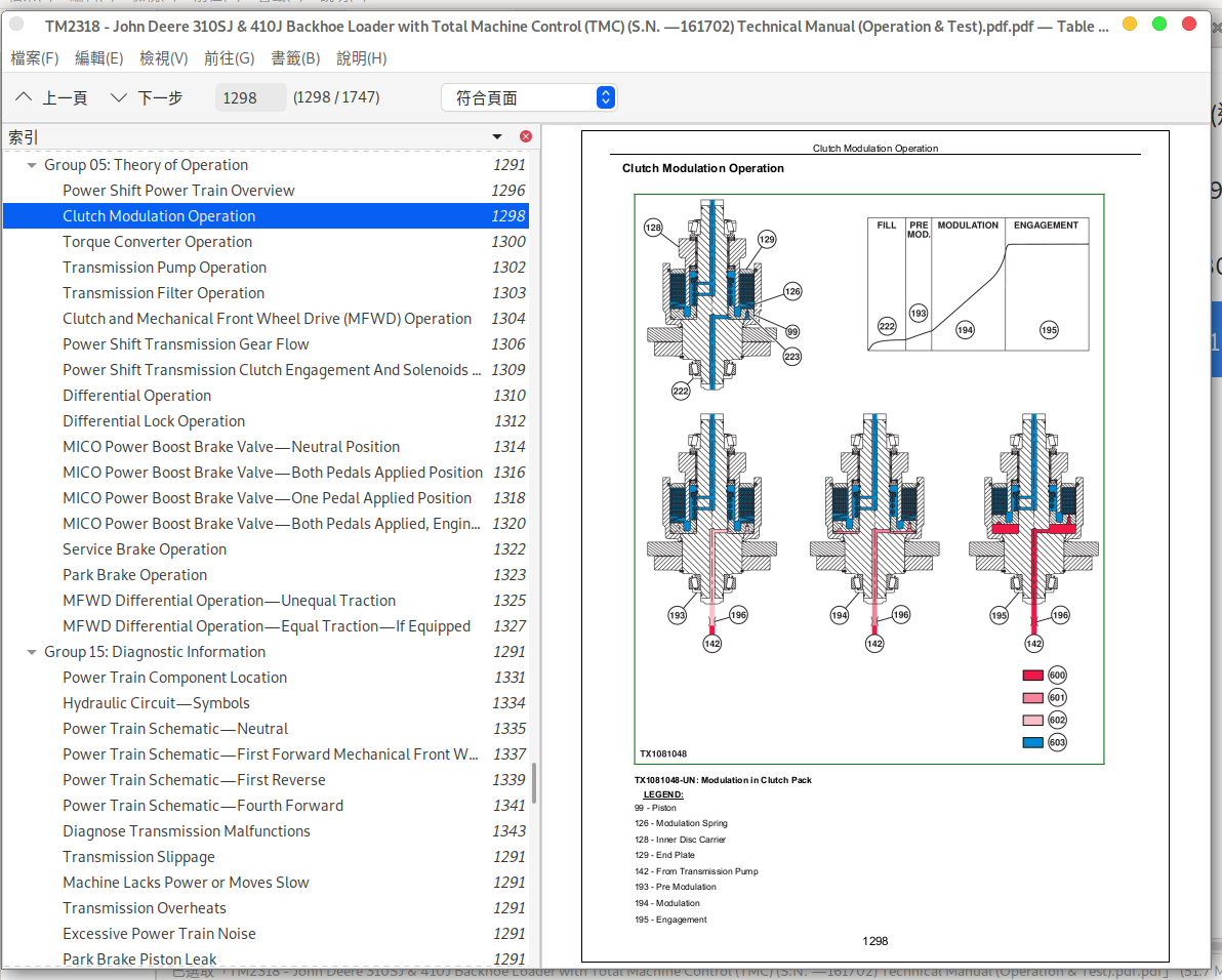
Clutch Modulation Operation
Torque Converter Operation
Transmission Pump Operation
Transmission Filter Operation
Clutch and Mechanical Front Wheel Drive (MFWD) Operation
Power Shift Transmission Gear Flow
Power Shift Transmission Clutch Engagement And Solenoids Activated
Differential Operation
Differential Lock Operation
MICO Power Boost Brake Valve—Neutral Position
MICO Power Boost Brake Valve—Both Pedals Applied Position
MICO Power Boost Brake Valve—One Pedal Applied Position
MICO Power Boost Brake Valve—Both Pedals Applied, Engine Off Position
Service Brake Operation
Park Brake Operation
MFWD Differential Operation—Unequal Traction
MFWD Differential Operation—Equal Traction—If Equipped
Group 15: Diagnostic Information
Power Train Component Location
Hydraulic Circuit—Symbols
Power Train Schematic—Neutral
Power Train Schematic—First Forward Mechanical Front Wheel Drive (MFWD) Engaged
Power Train Schematic—First Reverse
Power Train Schematic—Fourth Forward
Diagnose Transmission Malfunctions
Transmission Slippage
Machine Lacks Power or Moves Slow
Transmission Overheats
Excessive Power Train Noise
Park Brake Piston Leak
No Power to Mechanical Front Wheel Drive (MFWD)
No Power to One Wheel of Mechanical Front Wheel Drive (MFWD)
No Differential Lock Operation
Differential Lock Slips or Chatters When Engaged
Differential Lock Will Not Release
Rear Axle Overfilled With Oil
Poor Service Brakes
Brake Pedal Hard to Push
Service Brakes Will Not Release
Service Brakes Chatter or Noisy
Park Brake Will Not Hold
Park Brake Will Not Release
Group 20: Adjustments
Park Brake Release for Towing
Brake Pedal Adjustment
Brake Bleeding Procedure
Tracking Angle Check and Adjust
Toe-In Check and Adjust
Steering Angle Check and Adjust
Group 25: Tests
Transmission Oil Warm-Up Procedure
Transmission Oil Sampling Procedure—If Equipped
Power Shift Transmission Overall Test Connections, Ports, and Locations
Torque Converter Stall Speed Test
Torque Converter Inlet Pressure Test
Brake Valve Leakage Test
Park Brake Release Pressure Test
Transmission System Pressure Test
Service Brake Boost Pressure Test
Clutch Pressure Test
Differential Lock Pressure Test
Mechanical Front Wheel Drive (MFWD) Pressure Test
Cooler In and Cooler Out Pressure Test
Solenoid Circuit Leakage Test
Transmission Pump Flow Test
Section 9025: Hydraulic System
Group 05: Theory of Operation
Hydraulic Pump Operation
Power Limiting Valve Operation
Hydraulic Filter Operation
Steering Valve Operation
Ride Control Hydraulic Circuit Component Location and Valve Operation
Attachment Coupler Hydraulic Operation
Electro-Hydraulic System Theory of Operation
Electro-Hydraulic Solenoid Logic
Electro-Hydraulic Spool Valve Loader Boom, Bucket, Loader Auxiliary and Backhoe Auxiliary Valves Theory of Operation
Electro-Hydraulic Spool Valve Backhoe Swing Valve Theory of Operation
Electro-Hydraulic Spool Valve Backhoe Extend Theory of Operation
Electro-Hydraulic Spool Valve Direction and Magnitude Solenoids Theory of Operation
Electro-Hydraulic Spool Valve Backhoe Stabilizer Valve Theory of Operation
Electro-Hydraulic Spool Valve Assembly Load Sense Isolator and Pressure Compensator Theory of Operation
Electro-Hydraulic Spool Valve Mid-Inlet Theory of Operation
Electro-Hydraulic Spool Valve Relief Valve Theory of Operation
Electro-Hydraulic Spool Valve Anticavitation Valve and Plug Assembly Theory of Operation
Backhoe Distributed Function Valve Assembly Theory of Operation
Backhoe Distributed Function Valve Assembly Theory of Operation—Boom Raise/Lower Operation
Backhoe Distributed Function Valve Assembly Theory of Operation—Crowd In/Out Operation
Backhoe Distributed Function Valve Assembly Theory of Operation—Bucket Curl/Dump Operation
Distributed Function Valve Assembly Circuit Relief Valve Theory of Operation
Group 15: Diagnostic Information
Hydraulic Schematic
Hydraulic System Component Location
Load Sense Regulation Valve
All Backhoe Functions (Boom, Crowd, Bucket, Hammer) Slow
All Spool Valve Functions (Loader, Swing, Stabilizer, Auxiliary) Slow
Single Spool Valve Function (Loader, Swing, Stabilizer, Auxiliary) Slow
Single Backhoe Function (Boom, Crowd, Bucket, Hammer) Slow
All Functions Chatter
Single Spool Valve Function (Loader, Auxiliary) Chatter
Spool Valve Function (Swing, Extend) Chatter
Single Backhoe Function Chatter
All Spool Valve Functions (Loader, Swing, Extend, Stabilizer) Too Fast
Single Spool Valve Functions (Swing, Extend) Too Fast
All Backhoe Functions (Boom, Crowd, Bucket, Hammer) Fast
Single Backhoe Function (Boom, Crowd, Bucket, Hammer) Fast
No Hydraulics
No Spool Valve (Loader, Swing, Extend, Stabilizer, Auxiliary) Hydraulics
No Backhoe Functions
Spool Valve Functions Do Not Stop
Backhoe Functions Do Not Stop
Low Hydraulic Power
Excessive Engine Pulldown (All Functions)
Excessive Engine Pulldown (Single Backhoe Function)
One Function Slow in Combined Operation (Spool Valve Functions)
One Function Slow in Combined Operation (Backhoe Functions)
No Swing Function
Swing Wag
Hydraulic Oil Overheats
Spool Valve Function Only Moves in One Direction
Backhoe Function Drift
No Stabilizer Function
Foaming Oil
Hydraulic Pump Leaking
Backhoe Boom Valve Noise—In Neutral
Excessive Pump Noise
Slow Steering Hydraulics
No Steering Hydraulics
Hard Steering
Steering Valve Does Not Return to Neutral
No Response when Steering Wheel is Turned
Machine Turns in Opposite Direction
Excessive Vibration of the Steering Wheel
Machine Turns when Steering Valve is in Neutral
Steering Wheel Kickback
Excessive Steering Wheel Turns To Steer Machine
Erratic (“Spongy”) Steering
Steering Wheel "Locks" Up
Poor Centering of Steering Wheel (Wheels Continue to Move After Steering Wheel is Stopped)
Steering Wheel or Front Wheels Slowly Turn by Themselves When Using Backhoe or Loader
Steering Wheel Turns Apply Rear Axle Service Brakes
Steering Wheel Turns Freely With No Resistance or Action On Steered Wheels
Steering Wheel Turns With Slight Resistance and No Action On Steered Wheels
Wander—Vehicle Will Not Stay in a Straight Line
No Loader or Steering Hydraulics
Group 20: Adjustments
Ride Control Accumulator Charge Procedure
Ride Control Accumulator Charge Check Procedure
Ride Control Accumulator Hydraulic Pressure Release Procedure
Pilot Control Pressure Adjustment
Pilot Control Manifold Valve Accumulator Discharge Procedure
Group 25: Tests
JT02156A Digital Pressure and Temperature Analyzer Kit Installation
Hydraulic Oil Warmup Procedure
Hydraulic Oil Sampling Procedure—If Equipped
Hydraulic Circuit Pressure Release
Load Sense Relief Valve Pressure Test
Hydraulic Oil Cooler Restriction Test
Circuit Relief Valve Test With Remote Pump
Pump Load Sense Differential Pressure Test
Hydraulic Pump Flow Test
Hydraulic Return Pressure Test
Power Limiting Valve Test
Pilot Control Accumulator Charge Pressure Test
Steering System Leakage Test
Steering Cylinder Leakage Test
Function Drift Test
Hydraulic Cylinder Leakage Test
Section 9031: Heating and Air Conditioning
Group 05: Theory of Operation
Air Conditioning System Cycle Of Operation
Group 15: Diagnostic Information
Air Conditioning System Does Not Operate
Air Conditioner Does Not Cool Interior of Cab
Air Conditioner Runs Constantly, Too Cold
Interior Windows Continue to Fog
Heater System Does Not Operate
Heater Does Not Warm Interior of Cab
Air Conditioning and Heater System Component Location
Group 25: Tests
Proper Refrigerant Handling
R134a Refrigerant Cautions
R134a Air Conditioning System Test
Operating Pressure Diagnostic Chart
Expansion Valve Operation Test
Blower Switch Test
Blower Resistor Test
Heater Blower Motor Test
Freeze Control Switch Test
Air Conditioning Switch Test
Binary Pressure Switch Test
Compressor Clutch Coil Test
Air Conditioning System Leak Test
Refrigerant Hoses And Tubing Inspection
John Deere 310SJ and 410J Backhoe Loader (TMC) Service Manual (Operation & Test TM2318)
![]()