
John Deere 4044M, 4044R, 4049M, 4049R, 4052M, 4052R, 4066M, 4066R Tractors Diagnostic and Repair Service Manual (TM131019)
All Inclusive Technical Manual with Electrical Wiring Diagrams for John Deere Compact Utility Tractors 4044M, 4044R, 4049M, 4049R, 4052M, 4052R, 4066M & 4066R, with workshop information to maintain, diagnose, repair, and service like professional mechanics.
John Deere Compact Utility Tractors 4044M, 4044R, 4049M, 4049R, 4052M, 4052R, 4066M & 4066R workshop Diagnosis & Repair Manual includes:
* Numbered table of contents easy to use so that you can find the information you need fast.
* Detailed sub-steps expand on repair procedure information
* Numbered instructions guide you through every repair procedure step by step.
* Troubleshooting and electrical service procedures are combined with detailed wiring diagrams for ease of use.
* Notes, cautions and warnings throughout each chapter pinpoint critical information.
* Bold figure number help you quickly match illustrations with instructions.
* Detailed illustrations, drawings and photos guide you through every procedure.
* Enlarged inset helps you identify and examine parts in detail.
TM131019 - John Deere 4044M, 4044R, 4049M, 4049R, 4052M, 4052R, 4066M, 4066R Compact Utility Tractors Diagnosis & Repair Manual.PDF
TM131019 - John Deere 4044M, 4044R, 4049M, 4049R, 4052M, 4052R, 4066M, 4066R Compact Utility Tractors Diagnosis & Repair Manual.EPUB
Total Pages: 3,030 pages
File Format: PDF/EPUB/MOBI/AZW (PC/Mac/Android/Kindle/iPhone/iPad; bookmarked, ToC, Searchable, Printable)
Language: English
TALE OF CONTENTS
Foreword
General Information
Safety
General References
Technical Specific References
Fuel and Lubricants
Serial Number Locations
Engine Repair
Engine
Cooling System
Fuel, Air Intake, and Exhaust Repair
Fuel
Air Intake
Exhaust
Electrical Repair
Battery, Starter and Alternator
Electrical System Components
Wiring Harnesses
Transmissions Repair
Separation
Power Train-Hydrostatic
Power Train-Power Reverser
Final Drive Repair
MFWD
Differential
PTO
Steering and Brake Repair
Steering
Brake
Hydraulics Repair
Hydraulic Pump and Filter
Rockshaft
Range Control and Three Point Hitch
Selective Control Valve
Miscellaneous Repair
Hood and Side Panels
Fenders
Wheels
Cab/Open Operator’s Station Repair
Seat and Support
Control Console
Roll-Gard
Cab Components
Open Operator Station Components
Heating System
Air Conditioning System
Temperature Control, Belts, and Blower Motor
Diagnostic Trouble Codes
General References
Engine Control Unit (ECU) Diagnostic Trouble Codes
Instrument Cluster Control (ICC) Diagnostic Trouble Codes
Power Train Hydrostatic (PTH) Control Unit Diagnostic Trouble Codes
Power Train Reverser (PTR) Control Unit Diagnostic Trouble Codes
Observable Symptoms and System Diagnostics
General References
Engine Diagnostics
Fuel, Air Intake, Exhaust, and Cooling Diagnostics
Electrical Diagnostics
Electronic Control Unit Diagnostics
Drive Systems and Transmission Diagnostics
Steering and Brakes Diagnostics
Hydraulic Diagnostics
Cab/Open Operator`s Station Diagnostics
Engine Operation, Test, and Adjustments
General References
Calibrations, Preliminary Checks and Operational Checks
Theory of Operation
Tests and Adjustments
Fuel , Air Intake, Exhaust, and Cooling Operation, Test, and Adjustments
General References
Calibrations, Preliminary Checks and Operational Checks
Theory of Operation
Component and Connector Information
Tests and Adjustments
Electrical General and Theory of Operation
General References
Key Switch, Starter, and Alternator
Accessory Power and Horn
Control Module, Headlights, Signal, Work Lighting, and Warning Lights
Hydraulics, Rockshaft, and Diverter
Heating and Air Conditioning
Cruise Control
Windshield Wiper and Washer
Dome Light, Door Switch, Air Seat, and Radio
Instrument Control Cluster (ICC)
MFWD, Brakes, PTO, and Speed Sensor
Transmission Control Unit (TCU)
Engine Control Unit (ECU)
Electrical Schematics
General References
Electrical Schematics
Circuit Diagrams
Electrical Components and Connectors
General References
(SE1) Key Switch, Starter, and Alternator
(SE3-SE4) Accessory Power and Horn
(SE5-SE7) Control Module, Headlights, Signal, Work Lighting, and Warning Lights
(SE9) Junction Block Power
(SE10-SE11) Rear Trailer Connector
(SE13) Back-Up Alarm and Beacon Light
(SE14) Hydraulics, Rockshaft, and Diverter
(SE15) Power Port
(SE16-SE17) Heating and Air Conditioning
(SE18) Cruise Control
(SE19-SE20) Windshield Wiper and Washer
(SE22-SE23) Dome Light, Door Switch, Air Seat, and Radio
(SE24) Instrument Control Cluster (ICC)
(SE25-SE28) MFWD, Brakes, PTO, and Speed Sensor
(SE29) Transmission Control Unit (TCU)
(SE30) Engine Control Unit (ECU)
(SE32) Controller Area Network
Fuses and Relays
Ground Points
Interconnects
Electrical Tests and Adjustments
General References
Tests and Adjustments
Electronic Control Units
General References
Calibrations, Preliminary Checks and Operational Checks
Theory of Operation
Component and Connector Information
Test and Adjustments
Instrument Cluster Control (ICC)
Engine Control Unit (ECU)
Power Train Hydrostatic (PTH)
Power Train Reverser (PTR)
Power Train-Transmission Operation, Test, and Adjustments
General References
Calibrations, Preliminary Checks and Operational Checks-PTH
Calibrations, Preliminary Checks and Operational Checks-PTR
Theory of Operation-PTH
Theory of Operation-PTR
Schematics-PTH
Schematics-PTR
Component and Connector Information-PTH
Component and Connector Information-PTR
Tests and Adjustments-PTH
Tests and Adjustments-PTR
Final Drive Operation, Test, and Adjustments
General References
Calibrations, Preliminary Checks and Operational Checks
Theory of Operation
Component and Connector Information
Tests and Adjustments
Steering and Brakes Operation, Test, and Adjustments
General References
Calibrations, Preliminary Checks and Operational Checks-Steering
Calibrations, Preliminary Checks and Operational Checks-Brakes
Theory of Operation-Steering
Theory of Operation-Brakes
Schematics-Steering
Component and Connector Information-Steering
Component and Connector Information-Brakes
Tests and Adjustments-Steering
Tests and Adjustments-Brakes
Hydraulics Operation, Test, and Adjustments
General References
Calibrations, Preliminary Checks and Operational Checks
Theory of Operation
Schematics
Component and Connector Information
Tests and Adjustments
Cab/Open Operators Station Operation, Test, and Adjustments
General References
Calibrations, Preliminary Checks and Operational Checks
HVAC Theory of Operation
Seat Theory of Operation
Schematics
Component and Connector Information
Tests and Adjustments
Service Tools
General References
Dealer Fabricated and Service Tools
TABLE OF CONTENTS (exploded view)
10 - General Information
Alternative and Synthetic Lubricants
Avoid Backover Accidents
Avoid Contact with Agricultural Chemicals
Avoid Harmful Asbestos Dust
Avoid Heating Near Pressurized Fluid Lines
Avoid High-Pressure Fluids
Avoid Hot Exhaust
Clean Exhaust Filter Safely
Clean Vehicle of Hazardous Pesticides
Construct Dealer-Made Tools Safely
Decommissioning Proper Recycling and Disposal of Fluids and Components
Deliver Safely
Diesel Engine Coolant
Diesel Fuel
Engine Oil
Engine Serial Number
Follow Safety Instructions
Glossary of Terms
Grease
Handle Agricultural Chemicals Safely
Handle Fluids Safely342200224Avoid Fires
Handle Fuel Safely342200224Avoid Fires
Handling and Storing Diesel Fuel
Handling Batteries Safely
Illuminate Work Area Safely
Information Available in Sections, Groups and Subgroups
Install All Guards
Keep ROPS Installed Properly
Live With Safety
Lubricant Storage
Machine Product Identification Number
Metric Bolt and Screw Torque Values
Mixing of Lubricants
Park Machine Safely
Practice Safe Maintenance
Prepare for Emergencies
Prevent Machine Runaway
Recognize Safety Information
Remove Paint Before Welding or Heating
Replace Safety Signs
Serial Numbers
Service Accumulator Systems Safely
Service Cooling System Safely
Service Machines Safely
Service Tires Safely
Stay Clear of Rotating Drivelines
Support Machine Properly
Trademarks
Transmission and Hydraulic Oil
Transmission Serial Number
Transport Tractor Safely
Understand Signal Words
Unified Inch Bolt and Screw Torque Values
Use a Safety Chain
Use Proper Lifting Equipment
Use Proper Tools
Use Steps and Handholds Correctly
Wear Protective Clothing
Work in Clean Area
Work In Ventilated Area
20 - Engine Repair
05 - Engine
Cam Follower Inspection
Cam Follower Removal and Installation
Camshaft End Play Check
Camshaft Gear Removal and Installation
Camshaft Inspection
Camshaft Installation
Camshaft Removal
Camshaft Timing Gear Backlash Check
Check Connecting Rod Bearing Clearance
Check Connecting Rod Side Play
Crankcase Breather Remove and Install
Crankshaft and Main Bearing Component Inspection
Crankshaft and Main Bearing Installation
Crankshaft and Main Bearing Removal
Crankshaft End Play Check
Crankshaft Gear Replacement
Crankshaft Main Bearing Clearance Check
Crankshaft Rear Oil Seal Replacement
Cylinder Bore Deglazing
Cylinder Head Assembly Component Inspection
Cylinder Head Components
Cylinder Head Remove and Install
Cylinder Inspection
Cylinder Reboring
Engine Removal and Installation
Fan and Alternator Drive Belt Removal and Installation
Flywheel Housing Removal and Installation
Flywheel Removal and Installation
Grind Valve Seats
Idler Gear Bushing Replacement
Idler Gear Inspection
Idler Gear Removal and Installation
Intake and Exhaust Valves Remove and Install
Lap Valves
Piston and Connecting Rod Assembly Installation
Piston and Connecting Rod Assembly
Piston and Connecting Rod Assembly Removal
Piston and Connecting Rod Component Inspection
Piston and Connecting Rod Disassembly
Piston Cooling Nozzle Removal and Installation
Remove, Inspect, and Install Oil Pump
Rocker Arm Assembly Component Inspection
Rocker Arm Assembly
Rocker Arm Cover Remove and Install
Throttle Rod Removal and Installation
Timing Gear Cover Mounting Plate Removal and Installation
Timing Gear Cover Removal and Installation
Valve Guides Remove and Install
Valve Seat Removal and Installation
10 - Cooling
Charge Air Cooler (CAC) Removal and Installation
Coolant Pump Removal and Installation
Radiator Inspection
Radiator Removal and Installation
Thermostat Removal and Installation
211 - Diagnostic Trouble Codes
05 - General References
Diagnostic Trouble Codes Overview
Diagnostic Trouble Codes - Summary of References
Recall, Record, and Clear Codes
ECU - Engine Control Unit
ECU 000028.00 342200224 Primary Analog Throttle Signal Extremely High
ECU 000028.01 342200224 Primary Analog Throttle Signal Extremely Low
ECU 000028.03 342200224 Primary Analog Throttle Signal Out of Range High
ECU 000028.04 342200224 Primary Analog Throttle Signal Out of Range Low
ECU 000029.03 342200224 Secondary Throttle Signal Out of Range High
ECU 000029.04 342200224 Secondary Throttle Signal Out of Range Low
ECU 000029.08 342200224 Secondary Throttle Signal Abnormal
ECU 000091.03 342200224 Primary Analog Throttle Signal Out of Range High
ECU 000091.04 342200224 Primary Analog Throttle Signal Out of Range Low
ECU 000167.01 342200224 Charging System Voltage Extremely Low
ECU 000167.05 342200224 Charging System Circuit Has High Resistance
ECU 000237.13 342200224 VIN Option Code Security Data Conflict
ECU 000237.31 342200224 VIN Security Data Missing
ECU 001485.02 342200224 ECU Main Relay Invalid
ECU 003695.14 342200224 Diesel Particulate Filter Regeneration Special Instructions
ECU 522243.05 342200224 Engine Starter Solenoid Lockout Relay Driver Circuit Has High Resistance
ECU 522243.06 342200224 Engine Starter Solenoid Lockout Relay Driver Circuit Has Low Resistance
ECU 522590.12 342200224 Sensor Supply #1 Voltage Error
ECU 522596.09 342200224 No CAN Message Received From Source Address 1
ECU 522597.09 342200224 No CAN Message Received From Source Address 2
ECU 522599.09 342200224 Vehicle Controller CAN Communication Error #1
ECU 522600.09 342200224 Vehicle Controller CAN Communication Error #2
ECU 522601.09 342200224 Vehicle Controller CAN Communication Error #3
ECU 522609.09 342200224 Vehicle Controller CAN Communication Error #4
ECU 522618.09 342200224 Vehicle Controller CAN Communication Error #5
ECU 522619.09 342200224 Vehicle Controller Communications Error
ECU 522623.07 342200224 Dual Throttle Open Position Failure
ECU 522624.07 342200224 Dual Throttle Closed Position Failure
ECU 522730.12 342200224 Vehicle Immobilizer System CAN Communication Error
ECU 522744.04 342200224 ECU Power Supply Output #1 Circuit Has Low Resistance
ECU 522994.04 342200224 ECU Power Supply Output #2 Circuit Has Low Resistance
ECU 523471.06 342200224 ECU Power Supply Output #3 Circuit Has Low Resistance
ECU 342200224 Non-Tractor ECU Codes
ICC - Instrument Cluster Control
ICC 000096.03 342200224 Fuel Sender Voltage Above Normal, or Shorted to High Source
ICC 000110.00 342200224 Engine Coolant Temperature Data Valid But Above Normal Operating Range
ICC 000110.04 342200224 Engine Coolant Temperature Voltage Below Normal, or Shorted to Low Source
ICC 000110.09 342200224 Engine Coolant Temperature Abnormal Update Rate
ICC 000190.09 342200224 Engine Speed Abnormal Update Rate
ICC 000247.09 342200224 Engine Total Hours of Operation, Abnormal Update Rate
ICC 000628.02 342200224 Light Bulb Output Driver Data erratic, intermittent or incorrect
ICC 000628.12 342200224 Program Memory, Bad Intelligent Device or Component
ICC 000630.13 342200224 Program Memory Out of Calibration
ICC 000632.05 342200224 Engine Fuel Shutoff Current Below Normal or Open Circuit
ICC 000632.06 342200224 Engine Fuel Shutoff Current Above Normal or Grounded Circuit
ICC 000677.05 342200224 Engine Starter Motor Relay Current Below Normal or Open Circuit
ICC 000677.06 342200224 Engine Starter Motor Relay Current Above Normal or Grounded Circuit
ICC 002000.09 342200224 Source Address 0 Abnormal Update Rate
ICC 002003.09 342200224 Source Address 3 Abnormal Update Rate
ICC 002368.05 342200224 Left Turn Signal Lights Current Below Normal or Open Circuit
ICC 002368.06 342200224 Left Turn Signal Lights Current Above Normal or Grounded Circuit
ICC 002370.05 342200224 Right Turn Signal Lights Current Below Normal or Open Circuit
ICC 002370.06 342200224 Right Turn Signal Lights Current Above Normal or Grounded Circuit
ICC 002392.05 342200224 Alarm Horn Current Below Normal or Open Circuit
ICC 002807.05 342200224 Engine Fuel Shutoff 2 Control Current Below Normal or Open Circuit
ICC 002807.06 342200224 Engine Fuel Shutoff 2 Control Current Above Normal or Grounded Circuit
ICC 002808.03 342200224 Keypad Voltage Above Normal, or Shorted to High Source
ICC 003352.07 342200224 Engine Exhaust Pressure Regulator Vent Valve Position Not Responding or Out of Adjustment
ICC 003695.03 342200224 Diesel Particulate Filter Regeneration Inhibit Switch Voltage above normal, or shorted to high source
ICC 003719.09 342200224 Particulate Trap #1 Soot Load Percent Abnormal Update Rate
ICC 003721.09 342200224 Particulate Trap #1 Time Since Last Active Regeneration Abnormal Update Rate
ICC 522011.02 342200224 TCU is Not Responding, Data Erratic, Intermittent or Incorrect
ICC 523905.05 342200224 Front PTO Driver Current Below Normal or Open Circuit
ICC 523905.06 342200224 Front PTO Driver Current Above Normal or Short to Ground
ICC 524254.06 342200224 Transmission Enable Output Current Above Normal or Grounded Circuit
ICC 524264.31 342200224 Checksum Error Not Available or Condition Exists
PTH - Power Train Hydrostatic'
PTH 000084.08 342200224 MFWD Speed Abnormal Frequency
PTH 000084.31 342200224 MFWD Speed Not Available or Condition Exists
PTH 000091.03 342200224 Throttle Sensor Input Voltage Above Normal, or Shorted to High Source
PTH 000091.04 342200224 Throttle Sensor Input Voltage Below Normal, or Shorted to Low Source
PTH 000091.09 342200224 Throttle Sensor Abnormal Update Rate
PTH 000091.13 342200224 Throttle Sensor Out of Calibration
PTH 000091.15 342200224 Throttle Sensor Data Valid but Above Normal Operating Range - Least Severe Level
PTH 000091.16 342200224 Throttle Sensor Data Valid but Above Normal Operating Range - Moderately Severe Level
PTH 000091.17 342200224 Throttle Sensor Data Valid but Below Normal Operating Range - Least Severe Level
PTH 000091.18 342200224 Throttle Sensor Data Valid but Below Normal Operating Range - Moderately Severe Level
PTH 000158.00 342200224 Switch Battery Potential Data Valid but Above Normal Operation Range - Most Severe Level
PTH 000158.01 342200224 Switched Power Valid but Below Normal Operation Range - Most Severe Level
PTH 000168.00 342200224 Supply Power Valid but Above Normal Operational Range - Most Severe Level
PTH 000168.01 342200224 Supply Power Valid but Below Normal Operation Range - Most Severe Level
PTH 000190.09 342200224 Engine Speed Abnormal Update Rate
PTH 000190.15 342200224 Engine Speed Data Valid but Above Normal Operating Range - Least Severe Level
PTH 000190.16 342200224 Engine Speed Data Valid but Above Normal Operating Range - Moderately Severe Level
PTH 000190.17 342200224 Engine Speed Data Valid but Below Normal Operating Range - Least Severe Level
PTH 000190.18 342200224 Engine Speed Data Valid but Below Normal Operating Range - Moderately Severe Level
PTH 000191.00 342200224 Transmission Output Shaft Speed Data Valid but Above Normal Operational Range - Most Severe Level
PTH 000596.31 342200224 Cruise Control Enable Switch Not Available or Condition Exists
PTH 000599.03 342200224 Cruise Control Enable Switch Voltage Above Normal, or Shorted to High Source
PTH 000599.31 342200224 Resume Enable Switch Not Available or Condition Exists
PTH 000601.03 342200224 Resume Enable Switch Voltage Above Normal, or Shorted to High Source
PTH 000628.02 342200224 Program Memory Data Erratic, Intermittent or Incorrect
PTH 000628.12 342200224 Program Memory Bad Intelligent Device or Component
PTH 000630.14 342200224 Calibration Memory Special Instructions
PTH 000752.15 342200224 Transmission Secondary Shift Selector Data Valid but Above Normal Operating Range - Least Severe Level
PTH 000752.17 342200224 Transmission Secondary Shift Selector Data Valid but Below Normal Operating Range - Least Severe Level
PTH 000767.03 342200224 Transmission Hitch Assist Switch Voltage Above Normal, or Shorted to High Source
PTH 000810.14 342200224 Hitch Assist Speed Sensor Integrity is out of Range
PTH 000903.03 342200224 Hitch Assist Direction Switch Voltage Above Normal
PTH 001504.31 342200224 Operator Seat Switch Not Available or Condition Exists
PTH 002017.09 342200224 Source Address 17 Abnormal Update Rate
PTH 003509.00 342200224 Sensor Supply Voltage Data Valid but Above Normal Operational Range - Most Severe Level
PTH 003509.01 342200224 Sensor Supply Voltage Data Valid but Below Normal Operational Range - Most Severe Level
PTH 521991.00 342200224 Controller Temperature Data Valid but Above Normal Operational Range - Most Severe Level
PTH 521991.01 342200224 Controller Temperature Data Valid but Below Normal Operational Range - Most Severe Level
PTH 521991.15 342200224 Controller Temperature Data Valid but Above Normal Operating Range - Least Severe Level
PTH 521991.16 342200224 Controller Temperature Data Valid but Above Normal Operating Range - Moderately Severe Level
PTH 521991.17 342200224 Controller Temperature Data Valid but Below Normal Operating Range - Least Severe Level
PTH 521991.18 342200224 Controller Temperature Data Valid but Below Normal Operating Range - Moderately Severe Level
PTH 522019.04 342200224 ELX2 State Voltage Below Normal, or Shorted to Low Source
PTH 523498.03 342200224 Hitch Assist Voltage Above Normal or Shorted to High Source
PTH 523590.03 342200224 Machine Drive Forward Pedal Voltage Above Normal, or Shorted to High Source
PTH 523590.04 342200224 Machine Drive Forward Pedal Voltage Below Normal, or Shorted to Low Source
PTH 523590.08 342200224 Machine Drive Forward Pedal Abnormal Frequency or Pulse Width or Period
PTH 523590.13 342200224 Machine Drive Forward Pedal Out of Calibration
PTH 523590.14 342200224 Machine Drive Forward Pedal Special Instructions
PTH 523590.16 342200224 Machine Drive Forward Pedal Data Valid but Above Normal Operating Range - Moderately Severe Level
PTH 523590.18 342200224 Machine Drive Forward Pedal Data Valid but Below Normal Operating Range - Moderately Severe Level
PTH 523590.31 342200224 Machine Drive Forward Pedal Not Available or Condition Exists
PTH 523591.03 342200224 Machine Drive Reverse Pedal Voltage Above Normal, or Shorted to High Source
PTH 523591.04 342200224 Machine Drive Reverse Pedal Voltage Below Normal, or Shorted to Low Source
PTH 523591.08 342200224 Machine Drive Reverse Pedal Abnormal Frequency or Pulse Width or Period
PTH 523591.13 342200224 Machine Drive Reverse Pedal Out of Calibration
PTH 523591.14 342200224 Machine Drive Reverse Pedal Special Instructions
PTH 523591.16 342200224 Machine Drive Reverse Pedal Data Valid but Above Normal Operating Range - Moderately Severe Level
PTH 523591.18 342200224 Machine Drive Reverse Pedal Data Valid but Below Normal Operating Range - Moderately Severe Level
PTH 523591.31 342200224 Machine Drive Reverse Pedal Not Available or Condition Exists
PTH 523655.31 342200224 Forward & Reverse inputs both active Not Available or Condition Exists
PTH 523735.03 342200224 Clutch Driver Power Voltage Above Normal, or Shorted to High Source
PTH 523735.05 342200224 Clutch Driver Power Current Below Normal or Open Circuit
PTH 523735.06 342200224 Clutch Driver Power Current Above Normal or Grounded Circuit
PTH 523966.31 342200224 Come-Home Mode Procedure Detected
PTH 524061.03 342200224 Transmission Enable Command Voltage Above Normal, or Shorted to High Source
PTH 524061.04 342200224 Transmission Enable Command Voltage Below Normal, or Shorted to Low Source
PTH 524061.31 342200224 Transmission Enable Command Not Available or Condition Exists
PTH 524069.03 342200224 Machine Drive Valve Reverse Voltage Above Normal, or Shorted to High Source
PTH 524069.05 342200224 Machine Drive Valve Reverse Current Below Normal or Open Circuit
PTH 524069.13 342200224 Machine Drive Valve Reverse Out of Calibration
PTH 524069.15 342200224 Machine Drive Valve Reverse Data Valid but Above Normal Operating Range - Least Severe Level
PTH 524069.17 342200224 Machine Drive Valve Reverse Data Valid but Below Normal Operating Range - Least Severe Level
PTH 524071.03 342200224 Machine Drive Valve Forward Voltage Above Normal, or Shorted to High Source
PTH 524071.05 342200224 Machine Drive Valve Forward Current Below Normal or Open Circuit
PTH 524071.13 342200224 Machine Drive Valve Forward Out of Calibration
PTH 524071.15 342200224 Machine Drive Valve Forward Data Valid but Above Normal Operating Range - Least Severe Level
PTH 524071.17 342200224 Machine Drive Valve Forward Data Valid but Below Normal Operating Range - Least Severe Level - Least Severe Level
PTH 524254.03 342200224 Transmission Enable Output Voltage Above Normal, or Shorted to High Source
PTH 524254.04 342200224 Transmission Enable Output Voltage Below Normal, or Shorted to Low Source
PTH 524254.15 342200224 Transmission Enable Output Data Valid but Above Normal Operating Range - Least Severe Level
PTH 524254.17 342200224 Transmission Enable Output Data Valid but Below Normal Operating Range - Least Severe Level
PTR - Power Train Reverser
PTR 000158.00 342200224 Switch Battery Potential Data Valid but Above Normal Operation Range - Most Severe Level
PTR 000158.01 342200224 Switched Power Valid but Below Normal Operation Range - Most Severe Level
PTR 000168.00 342200224 Supply Power Valid but Above Normal Operational Range - Most Severe Level
PTR 000168.01 342200224 Supply Power Valid but Below Normal Operation Range - Most Severe Level
PTR 000190.09 342200224 Engine Speed Abnormal Update Rate
PTR 000191.17 342200224 Transmission Output Shaft Speed Data Valid but Below Normal Operating Range
PTR 000598.02 342200224 Bottom of Clutch Switch and Clutch Pedal Position Data erratic, Intermittent or Incorrect
PTR 000628.02 342200224 Program Memory Data Erratic, Intermittent or Incorrect
PTR 000630.13 342200224 Transmission Out of Calibration
PTR 000630.14 342200224 Calibration Memory Special Instructions
PTR 000752.03 342200224 PowrReverser Shuttle Control Voltage Above Normal, or Shorted to High Source
PTR 001638.00 342200224 Hydraulic Oil Temp Data Valid But Above Normal Operating Range - Most Severe Level
PTR 001638.03 342200224 Hydraulic Oil Temp Sensor Voltage Above Normal, or Shorted to High Source
PTR 001638.04 342200224 Hydraulic Oil Temp Sensor Voltage Below Normal, or Shorted to Low Source
PTR 001638.16 342200224 Hydraulic Oil Temp Data Valid But Above Normal Operating Range - Moderately Severe Level
PTR 002820.31 342200224 Direction Commanded with Operator not Present
PTR 002823.31 342200224 FNR Switch Forward and Reverse Directions Not available or Condition Exists
PTR 002826.31 342200224 FNR Switch Forward, Neutral, and Reverse Directions Not available or Condition Exists
PTR 002827.31 342200224 FNR Switch Neutral State Not available or Condition Exists
PTR 002828.15 342200224 FNR Switch Data Valid But Above Normal Operating Range - Least Severe Level
PTR 002828.17 342200224 FNR Switch Data Valid But Below Normal Operating Range - Least Severe Level
PTR 003509.00 342200224 Sensor Supply Voltage High Data Valid But Above Normal Operating Range- Most Severe Level
PTR 003509.01 342200224 Sensor Supply Voltage Low Data Valid But Below Normal Operational Range - Most Severe Level
PTR 521991.00 342200224 Controller Internal Temperature Data Valid But Above Normal Operating Range- Most Severe Level
PTR 521991.01 342200224 Controller Internal Temperature Valid But Below Normal Operational Range - Most Severe Level
PTR 521991.15 342200224 Controller Internal Temperature Data Valid But Above Normal Operating Range - Least Severe Level
PTR 521991.16 342200224 Controller Internal Temperature Data Valid But Above Normal Operating Range - Moderately Severe Level
PTR 521991.17 342200224 Controller Internal Temperature Data Valid But Below Normal Operating Range - Least Severe Level
PTR 521991.18 342200224 Controller Internal Temperature Data Valid But Below Normal Operating Range - Moderately Severe Level
PTR 523966.31 342200224 Come-Home Mode Procedure Detected
PTR 524022.31 342200224 FNR Switch Neutral State Not available or Condition Exists
PTR 524173.03 342200224 Clutch Pedal Voltage Above Normal, or Shorted to High Source
PTR 524173.04 342200224 Clutch Pedal Voltage Below Normal, or Shorted to Low Source
PTR 524173.08 342200224 Clutch Pedal Sensor Abnormal Frequency or Pulse Width or Period
PTR 524173.13 342200224 Clutch Pedal Sensor Out of Calibration
PTR 524173.14 342200224 Clutch Pedal Sensor Channels Mismatch
PTR 524173.16 342200224 Clutch Pedal Sensor Depressed Data Valid But Above Normal Operating Range - Moderately Severe Level
PTR 524173.18 342200224 Clutch Pedal Sensor Neutral Position Data Valid But Below Normal Operating Range - Moderately Severe Level
PTR 524173.31 342200224 Clutch Pedal Position Channel Compare Fault
PTR 524230.07 342200224 Enable Valve Mechanical System Not Responding or Out of Adjustment
PTR 524234.03 342200224 Enable Pressure Sensor Voltage Above Normal, or Shorted to High Source
PTR 524234.04 342200224 Enable Pressure Sensor Voltage Below Normal, or Shorted to Low Source
PTR 524282.31 342200224 Shuttle Shift Prevented Due To High Ground Speed Fault
212 - Observable Symptoms & System Diagnostics
Back-Up Alarm Problems
Brake Problems
CAN System Diagnosis
Charging System Problems
Codes After Adding _ Removing Control Units
Control Unit Problems
Control Unit Programming Failed
Door Switch and Dome Lamp Problems
Electrical Connector Problems
Engine Diagnostics
Engine System Problems
Excessive Fuel Consumption
Fuel and Air System Problems
Horn Problems
HVAC Problems
Lighting System Problems
MFWD Problems
Observable Symptoms and System Diagnostics - Summary of References
Park Position Problems
Power Outlet Problems
Power Train Hydrostatic (PTH) Transmission Problems
Power Train Reverser (PTR) Transmission Problems
Programming Multiple Control Units
Rear Differential Lock Problems
Rear PTO Problems
Rockshaft Problems
SCV Problems
Seat Problems
Starting System Problems
Steering Problems
Trailer Connector and Junction Block Problems
Wiper Problems
220 - Engine Operation, Test and Adjustments
Cylinder Compression Pressure Test
Cylinder Leakage Test
Engine Information
Engine Oil Pressure Test
Engine Operation, Test, and Adjustments - Summary of References
High Idle Speed Adjustment
Low Idle Speed Adjustment
Lubrication System Operation
Symptom Engine Performance
System Lubrication
Torque Capsule Adjustment
Valve Clearance Adjustment
Valve Lift Check
230 - Fuel, Air Intake & Exaust Repair Operation, Test and Adjustments)
Air Cleaner and Intake Components
Air Filter Restriction Indicator Check
Air Intake Operational Checks
Air Intake System Operation
Check Turbocharger Rotor Shaft Axial Play
Check Turbocharger Rotor Shaft Radial Play
Cooling Operational Checks
Cooling System Operation
Cooling System Pressure Test
Exhaust Valve Actuator Rod Adjustment
Extending Turbocharger Life
Fan and Alternator Drive Belt Tension Check and Adjustment
Fuel , Air Intake, Exhaust, and Cooling Operation, Test, and Adjustments - Summary of References
Fuel Injection Nozzle Test
Fuel Operational Checks
Fuel Pump Supply Pressure Test
Fuel Supply Components
Fuel System Bleeding Procedure
Fuel System Operation
Injection Pump Static Timing Adjustment
Radiator Cap Pressure Test
Thermostat Opening Test
Throttle Rod Check and Adjustment
Turbocharger Components
Turbocharger Operational Checks
Turbocharger Operation
Turbocharger Seven-Step Inspection
Turbocharger Waste Gate Test
240A - Electrical General and Theory of Operation
Charging System Theory of Operation
Circuit Malfunctions
Circuit Types
Come Home Mode
Control Module Theory of Operation
Cruise Control Module Theory of Operation
Cruise Control Switch Theory of Operation
Diverter Valve Theory of Operation
Electrical Designators
Electrical General and Theory of Operation - Summary of References
Electrical Procedure
Electrical Schematic Symbols
Hitch Assist Theory of Operation
HVAC Theory of Operation
Hybrid Exhaust Actuator Control Theory of Operation
Instrument Cluster Control (ICC) Theory of Operation
MFWD Circuit Operation
Power Circuit Operation
Power Train Hydrostatic (PTH) Theory of Operation
Power Train Reverser (PTR) Theory of Operation
Radio Theory of Operation
Reading Wiring Schematics and Diagrams
Rear PTO Theory of Operation
Relay Circuit Types
Starting Circuit Theory of Operation
Troubleshooting Unresolved Electrical _ Electronic Problems
Using a Digital Multimeter
Using a Probe Light
Visually Inspect Electrical System
Windshield Wiper and Washer Theory of Operation
Wiring Diagram and Schematic Information
240B - Electrical Schematics
Accessory Power Schematic (SE3)
Air Conditioning Schematic (SE17)
Air Seat Schematic (SE23)
Back-Up Alarm Schematic (SE13A)
Beacon Light Schematic (SE13B)
Brake Switch Schematic (SE28)
Cab Work Lighting Schematic (License and Clearance Lights) (SE7B)
Cab Work Lighting Schematic (SE5B)
Controller Area Network Schematic (SE32)
Control Module, Headlights, Signal, and Warning Lights Schematic (License and Clearance Lights) (SE7A)
Control Module, Headlights, Signal, and Warning Lights Schematic (SE5A)
Creep to Reposition Schematic (SE31)
Cruise Control Schematic (SE18)
Diverter _ Rockshaft Downforce Schematic (SE14B)
Dome Light, Door Switch, and Radio Schematic (SE22)
Dual Rear Continuous Schematic (SE14C)
Electrical Schematics - Summary of References
Engine Control Unit (ECU) Schematic (SE30)
Front Windshield Wiper and Washer Schematic (SE19)
Heating Schematic (SE16)
Horn Schematic (SE4)
Instrument Control Cluster (ICC) Schematic (SE24)
Junction Block Power Schematic (SE9)
Key Switch, Starter, and Alternator342200224with ECU Schematic (SE1A)
Key Switch, Starter, and Alternator342200224without ECU Schematic (SE1B)
Mechanical Front-Wheel Drive (MFWD) Schematic (SE27)
Open Operator Station Work Lighting Schematic (License and Clearance Lights) (SE7C)
Open Operator Station Work Lighting Schematic (SE5C)
Power Port Schematic (SE15)
Rear Trailer Connector Schematic (License and Clearance Lights) (SE11)
Rear Trailer Connector Schematic (SE10)
Rear Windshield Wiper and Washer Schematic (SE21)
Seat Switch, PTO, and Speed Sensor Schematic (SE25)
Third EH Hydraulics Schematic (SE14A)
Transmission Control Unit (TCU) Schematic342200224Hydrostatic Transmission (SE29A)
Transmission Control Unit (TCU) Schematic342200224PowrReverser Transmission (SE29B)
240C - Electrical Components & Connectors
10 - Theory of Operation
20 - Diagnostics
30 - Tests and Adjustments
40 - Schematics (Model Year -2011)
45 - Schematics (Model Year 2012-)
50 - Connector Information
A01X1 Instrument Control Cluster
A01X2 Instrument Control Cluster
A01X3 Instrument Control Cluster
A01X4 Instrument Control Cluster
A02 Main Fuse Block
A04 Radio
A05 Air Seat
A06 Transmission Control Unit (TCU)342200224HST
A06 Transmission Control Unit (TCU)342200224PRT
A09X1 Engine Control Unit (ECU) Connector
A09X2 Engine Control Unit (ECU) Connector
A911 CAN Terminating Resistor
Accessory Power Circuit Diagram (SE3)
Air Conditioning Circuit Diagram (SE17)
Air Seat Circuit Diagram (SE23)
B01 Fuel Sender
B02 Fuel Sender
B03 Air Filter Restriction Switch
B04 Engine Oil Pressure Switch
B05 Engine Coolant Temperature Sensor
B06 Hydraulic Temperature Switch
B07 A _ C Deicing Switch
B08 DPF Inlet Temperature Sensor
B09 DPF Mid-Temperature Sensor
B10 Hydraulic Oil Temperature Sensor
B11 Pressure Enable Sensor
B23 A _ C High _ Low Pressure Switch
B240 Right Speaker
B241 Left Speaker
B5100 Fuel Rail Pressure Sensor
B5114 Manifold Air and Exhaust Pressure Sensor
B5206 Manifold Air Temperature Sensor
B5207 EGRTemperature Sensor
B5208 Engine Coolant Temperature Sensor
B5209 Fuel Temperature Sensor
B5215 Turbocharger Compressor Inlet Temperature Sensor
B5216 Exhaust Manifold Temperature Sensor
B5301 Crankshaft Position Sensor
B5302 Camshaft Position Sensor
Back-Up Alarm Circuit Diagram (SE13A)
Beacon Light Circuit Diagram (SE13B)
Brake Switch Circuit Diagram (SE28)
Cab Work Lighting Circuit Diagram (License and Clearance Lights) (SE7B)
Cab Work Lighting Circuit Diagram (SE5B)
Controller Area Network Circuit Diagram (SE32)
Control Module, Headlights, Signal, and Warning Lights Circuit Diagram (License and Clearance Lights) (SE7A)
Control Module, Headlights, Signal, and Warning Lights Circuit Diagram (SE5A)
Cruise Control Circuit Diagram (SE18)
DE5 Dual Rear Continuous Diode
DE6 Diverter Downforce Diode
DE7 Diverter Power Diode
Diverter _ Rockshaft Downforce Circuit Diagram (SE14B)
Dome Light, Door Switch, and Radio Circuit Diagram (SE22)
Dual Rear Continuous Circuit Diagram (SE14C)
E01 Left Front Headlight
E02 Right Front Headlight
E03 Left Tail _ Turn _ Brake _ Warning Light
E05 Left Front Work Light
E06 Right Front Work Light
E08 Right Tail _ Turn _ Brake _ Warning Light
E11 Right Tail _ Turn _ Brake _ Warning _ Clearance Light
E12 Left Tail _ Turn _ Brake _ Warning _ Clearance Light
E14 Left Rear Work Light
E16 Beacon Light
E17 Left Tail _ Brake Light
E18 Right Tail _ Brake Light
E20 Left Fender Work Light
E21 Right Fender Work Light
E22 Left Rear Turn _ Warning Light
E23 Left Rear Work Light
E24 Right Rear Work Light
E25 Right Front Turn _ Warning Light
E26 Right Rear Turn _ Warning Light
E27 License Plate Light
E28 Left Front Turn _ Warning Light
E29 Right Front Work Light
E30 Left Front Work Light
E31 Right Front Turn _ Warning _ Clearance Light
E32 Left Front Turn _ Warning _ Clearance Light
E41 Left Front Headlight
E42 Right Front Headlight
E43 Right Tail _ Turn _ Brake Light
E44 Left Tail _ Turn _ Brake Light
EH Hydraulics Load Center
Electrical Components and Connectors - Summary of References
Engine Control Unit (ECU) Circuit Diagram (SE30)
F23 (20A) ECU Fuse
F24 (500A) Fusible Link
F27 (50A) Glow Plug Fuse
F28 (50A) Load Center Fuse
F29 (80A) Alternator Fuse
F30 (10A) Diverter Downforce Fuse
Front Windshield Wiper and Washer Circuit Diagram (SE19)
G01 Battery
G02 Alternator
H01 Audible Alarm
H02 Back-Up Alarm
H03 Horn
H04 Audible Alarm
H05 Audible Alarm
H10 Hydraulic Oil Temperature Indicator
Heating Circuit Diagram (SE16)
Horn Circuit Diagram (SE4)
Instrument Control Cluster (ICC) Circuit Diagram (SE24)
Junction Block Power Circuit Diagram (SE9)
K01 Starter Relay
K02 Glow Plug Relay
K03 Fuel Shut Off Relay
K04 Starter Relay
K05 Accessory Power Relay
K09 Right Power Relay
K10 Left Power Relay
K11 Right Blower Relay
K12 Left Blower Relay
K15 Fuel Shut Off Relay
KE11 Diverter Downforce Relay
Key Switch, Starter, and Alternator342200224with ECU Circuit Diagram (SE1A)
Key Switch, Starter, and Alternator342200224without ECU Circuit Diagram (SE1B)
Load Center Fuses and Relays
M01 Starter Motor _ Solenoid
M02 Fuel Pump
M03 Front Wiper Motor
M04 Rear Washer Pump
M05 Front Washer Pump
M06 Exhaust Valve Actuator
M07 Left HVAC Blower Motor
M08 Right HVAC Blower Motor
M11 Rear Wiper Motor
M23 A _ C Compressor Clutch
Mechanical Front-Wheel Drive (MFWD) Circuit Diagram (SE27)
Open Operator Station Work Lighting Circuit Diagram (License and Clearance Lights) (SE7C)
Open Operator Station Work Lighting Circuit Diagram (SE5C)
P01 Forward Pedal Sensor
P02 Reverse Pedal Sensor
P03 Hand Throttle Sensor342200224with ECU
P03 Hand Throttle Sensor342200224without ECU
P04 Clutch Pedal Sensor
P05 Foot Throttle Sensor
Power Port Circuit Diagram (SE15)
R05 PowrReverser Shuttle Control
R21 Manifold Air Heater
R5606 Resistor
Rear Trailer Connector Circuit Diagram (License and Clearance Lights) (SE11)
Rear Trailer Connector Circuit Diagram (SE10)
Rear Windshield Wiper and Washer Circuit Diagram (SE21)
S01 Key Switch
S02 Control Module (License and Clearance Lights)
S02 Control Module
S03 PTO ON _ OFF Switch
S04 540 Speed PTO Sensing Switch
S05 Park Brake Force Switch
S06 DPF Differential Pressure Switch
S07 Clutch Bottom of Travel Switch
S08 Third Function Switch
S09 Dual Rear Continuous Switch
S10 Third Function Selection Switch
S11 Control Module (License and Clearance Lights)
S12 Forward Neutral Reverse (FNR) Switch
S13 Door Switch
S14 Rear Work Light Switch
S15 Horn Switch
S16 Beacon Light Switch
S17 PTO ON _ OFF Switch (Front)
S18 Cruise Control Module
S19 Cruise Control Module
S20 Front Wiper Switch
S21 Rear Wiper Switch
S22 A _ C ON _ OFF Switch
S24 HVAC Blower Switch
S27 Diverter _ Rockshaft Downforce Switch
S33 MFWD Speed Sensor
S34 Hitch Assist Module
S35 C Range Speed Sensor
S36 A Range Switch
S38 Seat Switch
S40 MFWD Engagement Sensing Switch
S41 Brake Switch
S42 Park Brake Switch
S46 Cruise Control Switch
S50 Park Brake Switch
S51 Hitch Assist ON _ OFF Switch
S52 Dome Light
Seat Switch, PTO, and Speed Sensor Circuit Diagram (SE25)
Third EH Hydraulics Circuit Diagram (SE14A)
Transmission Control Unit (TCU) Circuit Diagram342200224Hydrostatic Transmission (SE29A)
Transmission Control Unit (TCU) Circuit Diagram342200224PowrReverser Transmission (SE29B)
V2 Diverter Diode
X03 Junction Block
X04 Power Port
X05 Rear Trailer Connector342200224Open Operator Station
X06 Cab _ OOS Chassis Harness to Glow Plug Harness
X07 Cab _ OOS Chassis Harness to DPF Engine Harness
X08 OOS Chassis Harness to Right-Hand Fender Harness
X09 OOS Chassis Harness to Right-Hand Fender Harness
X102 Service Advisor Connector
X10 Rear Trailer Connector342200224Cab
X11 Cab _ OOS Chassis Harness to Grille Harness
X12 Rear Trailer Connector342200224Cab
X13 Lower Cab Harness to Front PTO Jumper Harness
X15 OOS Chassis Harness to Creep to Reposition Harness
X16 Cab _ OOS Chassis Harness to Grille Harness
X17 Third EH Hydraulics Harness to Mast Extension Harness
X18 Third EH Hydraulics Harness to Mast Extension Harness
X19 Third EH Hydraulics Harness to Mast Extension Harness
X20 OOS Chassis Harness to Engine Harness
X21 OOS Chassis Harness to Engine Harness
X22 OOS Chassis Harness to Engine Harness
X23 OOS Chassis Harness to Engine Harness
X25 Rear Trailer Connector342200224Open Operator Station
X26 OOS Chassis Harness to Left Fender Hitch Assist and Fender Light Harness
X27A Right-Hand Fender Harness to Diverter _ Rockshaft Downforce Harness
X27B Right-Hand Fender Harness to Third EH Hydraulics Harness
X28 Lower Cab Chassis Harness to Right Tail Light Extension Harness
X29 Lower Cab Chassis Harness to Left Tail Light Extension Harness
X31 Cab _ OOS Chassis Harness to Front PTO Harness
X32A Diverter _ Rockshaft Downforce Harness to Diverter _ Rockshaft Harness
X32B Third EH Hydraulics Harness to Diverter _ Rockshaft Harness
X33 OOS Chassis Harness to Right-Hand Fender Harness
X34 OOS Chassis Harness to Right-Hand Fender Harness
X35 OOS Chassis Harness to Left-Hand Fender Harness
X40 Cab Chassis Harness to 540 PTO Harness
X44 Left Work Light Split Harness to Left Rear Work Light Harness
X45 OOS Chassis Harness to Right Work Light Split Harness
X46 OOS Chassis Harness to Left Work Light Split Harness
X47 Right Work Light Split Harness to Right Front Work Light Harness
X48 Left Work Light Split Harness to Left Front Work Light Harness
X50 Cab Chassis Harness to Lower Cab Chassis Harness
X54A Lower Cab Chassis Harness to Diverter _ Rockshaft Downforce Harness
X54B Lower Cab Chassis Harness to Third EH Hydraulics Harness
X66 Lower Cab Chassis Harness to Roof Harness
X67 Lower Cab Chassis Harness to Roof Harness
X76 Lower Cab Chassis Harness to Rear Trailer Connector Harness
X77 Lower Cab Chassis Harness to Rear Trailer Connector Harness
X78 OOS Chassis Harness to Rear Trailer Connector Harness
XGND14 Beacon Ground
XGND1 Chassis Ground
XGND20 Front Wiper Ground
XGND3 Cab Platform Ground
Y01 Rear PTO Solenoid
Y02 Diverter _ Rockshaft Downforce Solenoid
Y03 Front PTO Solenoid
Y04 Third Function A Solenoid
Y05 Forward Proportional Solenoid
Y06 Reverse Proportional Solenoid
Y07 Third Function B Solenoid
Y08 Dual Rear Continuous Solenoid
Y09 Fuel Solenoid
Y10 Forward _ Reverse Enable Solenoid
Y11 Forward Proportional Solenoid
Y12 Reverse Proportional Solenoid
Y5006 Fuel Injector Solenoid 1
Y5007 Fuel Injector Solenoid 2
Y5008 Fuel Injector Solenoid 3
Y5009 Fuel Injector Solenoid 4
Y5400 EGR Valve
Y5401 Air Throttle Actuator
240D - Electrical Tests and Adjustments
10 - Theory of Operation
20 - Diagnostics
30 - Tests and Adjustments
40 - Schematics (Model Year -2011)
45 - Schematics (Model Year 2012-)
50 - Connector Information
A _ C Compressor Circuit Test
Alternator Circuit Test
Battery Inspection Test
CAN Network Voltage Checks
Connector Test
Control Module Test
Diode Test
ECU342200224Engine Control Unit Test
Electrical Tests and Adjustments - Summary of References
Fuse Test
How to Use Electrical Tests and Adjustments Information
ICC342200224Instrument Cluster Control Unit Test
Light Test
Miscellaneous Component Test
Motor Test
Open Circuit Load Test
PTH342200224Power Train Hydrostatic Control Unit Test
PTR342200224Power Train Reverser Control Unit Test
Pump Test
Relay Test
Resistor Test
Sensor Test
Solenoid Test
Switch Test
245 - Electronic Control Units
CAN Bus Message Structure
CAN Bus Theory of Operation
CAN Communication Fault Checks
Control Unit Addresses342200224Access
Control Unit Connectors and Components
Control Unit Messaging Errors
Diagnostic Addresses342200224Engine Control Unit (ECU)
Diagnostic Addresses342200224Instrument Cluster Control (ICC)
Diagnostic Addresses342200224Power Train Hydrostatic (PTH)
Diagnostic Addresses342200224Power Train Reverser (PTR)
Electronic Control Units342200224Summary of References
Entering Diagnostic and Calibration Modes
Instrument Cluster Control (ICC) Beep Mode Without Speed Sensors
Instrument Cluster Control (ICC) Beep Mode With Speed Sensors
Instrument Cluster Control (ICC) Configuration and Calibration
Keep Electronic Control Unit Connectors Clean
Monitoring CAN Bus Traffic Data
Power Train Hydrostatic (PTH) Beep Mode
Power Train Hydrostatic (PTH) Beep Mode With Speed Sensors
Power Train Hydrostatic (PTH) Control Unit342200224System Calibration
Power Train Reverser (PTR) Beep Mode
Power Train Reverser (PTR) Beep Mode With Speed Sensors
Power Train Reverser (PTR) Control Unit342200224System Calibration
Programming Control Units
Rolling Tire Circumference342200224Calibration
Servicing Electronic Control Units
System Address Beep Test
Troubleshooting Control Unit Programming
Troubleshooting Electronic Controllers
Troubleshooting Unresolved Problems
VIN Security Fault Diagnosis
Welding Near Electronic Control Units
250 - Power Train - Transmission Operation, Test and Adjustments
4 Speed Transmission Operation342200224PTR Transmission
Charge Pump Pressure Test342200224PTH Transmission
Clutch Control Valve Operation - Forward342200224PTR Transmission
Clutch Control Valve Operation - Neutral342200224PTR Transmission
Clutch Control Valve Operation - Reverse342200224PTR Transmission
Clutch Control Valve Theory of Operation342200224PTR Transmission
Clutch Operation - Forward342200224PTR Transmission
Clutch Operation - Reverse342200224PTR Transmission
Differential Power Flow and Lock342200224PTR Transmission
Forward Clutch Pressure Test342200224PTR Transmission
Hydrostatic High Pressure Relief Test342200224PTH Transmission
Install Test Equipment 50-1
Install Test Equipment 50-2
Install Test Equipment 50-3
Install Test Equipment 50-4
Install Test Equipment 50-5
Install Test Equipment 50-6
Lube Pressure Test342200224PTR Transmission
MFWD Power Operation342200224PTR Transmission
Power Train342200224Transmission Operation, Test, and Adjustments Summary of References
PTH Center Plate Components
PTH Drive Shaft Components
PTH Drive System Components
PTH Front Drive Components
PTH Transmission Components
PTH Transmission Housing Components
PTH Transmission342200224Operational Checks
PTH Transmission342200224Preliminary Checks
PTR Clutch Components
PTR Clutch Housing Components
PTR Control Valve Components
PTR Manual Shifter, Range Shifting Components
PTR MFWD Parallel Shaft Gear Drive Components
PTR Oil Filter and Lines Components
PTR Parallel Shaft Gear Drive, PTO Gears Components
PTR PTO Clutch Brake Assembly Components
PTR Range Shift Components
PTR Speed Shift Components
PTR Speed Shifter Components
PTR Transmission342200224Operational Checks
PTR Transmission342200224Preliminary Checks
Range Transmission Operation342200224PTR Transmission
Range Transmission Power Flow342200224PTH Transmission
Reverse Clutch Pressure Test342200224PTR Transmission
Steering _ Charge Pump Circuit Schematic342200224PTH Transmission
Steering _ Charge Pump Circuit Schematic342200224PTR Transmission
System Pressure Test342200224PTR Transmission
System Relief Valve Adjustment342200224PTR Transmission
Transmission Operation342200224PTH Transmission
255 - Final Drive Operation, Test, and Adjustments
2-Speed Rear PTO Components
2 Speed Rear PTO Operation
Differential and MFWD - Operational Checks
Differential and MFWD - Preliminary Checks
Differential Backlash Adjustment
Differential Gear Components
Differential Lock Components
Differential Pinion Shaft Adjustment
Differential Power Flow and Lock Operation
Final Drive Operation, Test, and Adjustments Summary of References
Front Drive Components342200224MFWD
Install Test Equipment 50-1
Install Test Equipment 50-2
MFWD Final Drive Components
MFWD Power Flow Operation
MFWD Power Operation
PTH Differential Pinion Shaft Components
PTO Clutch and Brake Operation
PTO Clutch _ Brake Assembly Components
PTO - Operational Checks
PTO - Preliminary Checks
PTO Proportional Valve Components
PTO Valve Flow Test
PTO Valve Pressure Test
Range Shift Components
Rear Axle and Final Drive Components
Rear PTO Components
Rear PTO Operation
260 - Steering and Brake Operation, Test and Adjustments
Brake Housing Components
Brake Pedal Adjustment
Brake Pedals and Linkage Components
Brakes - Operational Test
Brakes - Preliminary Check
Brakes System Operation
Brake Switch Adjustment
Brake System Components
Install Test Equipment 60-1
Install Test Equipment 60-2
Park Brake Adjustment
Park Brake Components
Steering and Brakes Operation, Test, and Adjustments Summary of References
Steering Control Unit (SCU) Components
Steering - Operational Check
Steering - Preliminary Check
Steering Pressure Check
Steering Pump Flow Test
Steering System Components
Steering System Operation
Steering System Schematic
Steering System Test
Toe-In Adjustment
270 - Hydraulics Operation, Test and Adjustments
Diverter Valve Components (If Equipped)
Dual Rear Selective Control Valve (SCV) Components (If Equipped)
Dual Rear Selective Control Valve (SCV) Operation
Dual Selective Control Valve (SCV) Components
Dual Selective Control Valve (SCV) Operation
Heating Hydraulic Oil
Hydraulic Diverter Valve Operation
Hydraulic Filter Components
Hydraulic Functional Schematics
Hydraulic Pump Flow Test
Hydraulics - Operational Check
Hydraulics - Preliminary Check
Hydraulics - Summary of References
Hydraulic System Bleed Procedure
Hydraulic System Components
Hydraulic System Operation
Install Test Equipment 70-1
Install Test Equipment 70-2
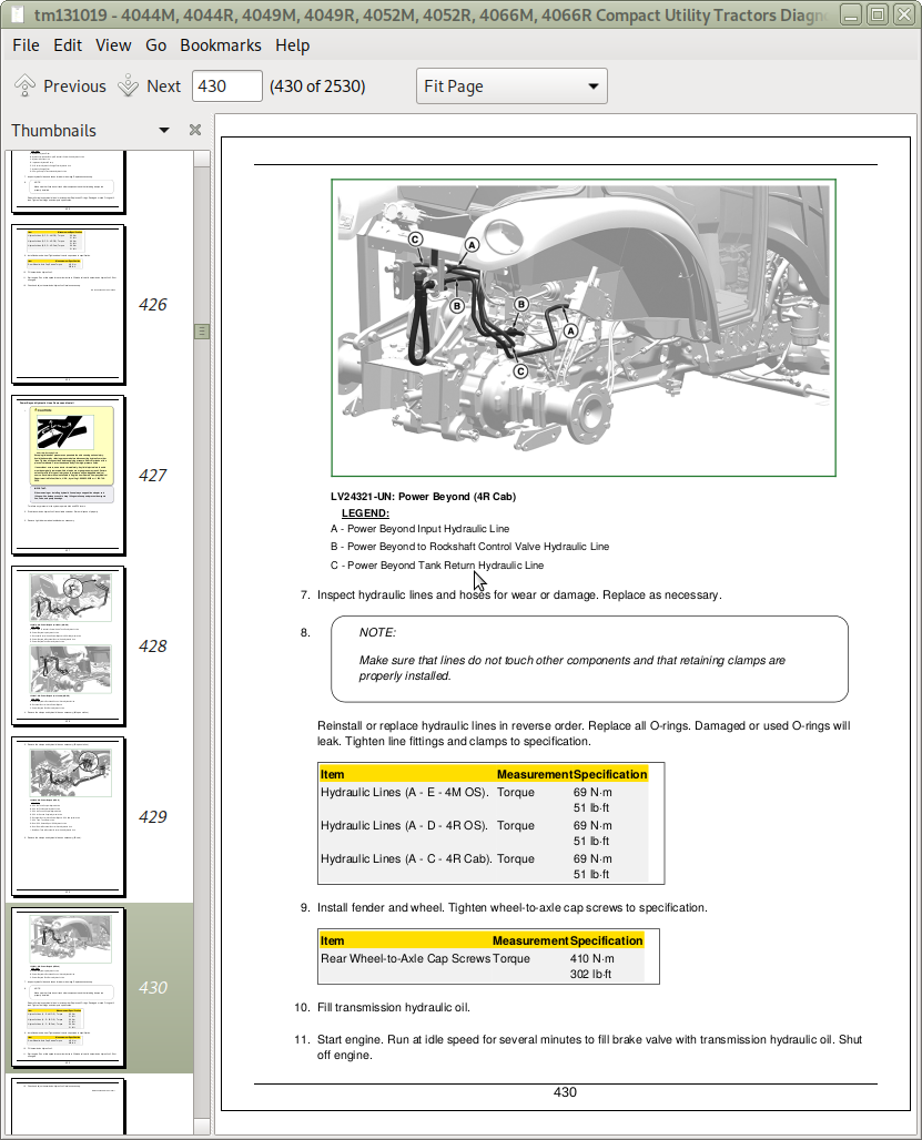
Power Beyond Components (If Equipped)
Power Beyond Operation
Rate of Drop _ Stop Valve Adjustment
Rate of Drop _ Stop Valve Operation
Rockshaft Cable Adjustment
Rockshaft Control Valve Components
Rockshaft Leakage Test
Rockshaft Lift Cycle Test
Rockshaft Position Feedback Linkage Adjustment
Rockshaft Surge Relief Test
Rockshaft Valve Operation
SCV Control Cable Adjustment
System Pressure Relief Valve Test and Adjustment
Third Selective Control Valve (SCV) Components (If Equipped)
Third Selective Control Valve (SCV) Operation
290 - Cab_Operator's Station Operation, Test and Adjustments
Add Refrigerant Oil to System
Air Conditioning Temperature Control Switch Cable Adjustment
Cab _ Open Operators Station Operation, Test, and Adjustments Summary of References
Compressor Clutch Hub Clearance Check
Compressor Oil Charge Check
Compressor Shaft Seal Leakage Test
Determine Correct Refrigerant Oil Charge
Evaporator _ Heater Core Leak Test
Expansion Valve Bench Test
Heater Control Valve Leak Test
Heater Temperature Control Cable Adjustment
Install Test Equipment 90-1
Operator Station - Air Conditioning Compressor Operation
Operator Station - Air Conditioning Condenser Operation
Operator Station - Air Conditioning Dual Pressure Switch Operation
Operator Station - Air Conditioning Evaporator Operation
Operator Station - Air Conditioning Expansion Valve Operation
Operator Station - Air Conditioning ON _ OFF Switch and Temperature Control Knob Operation
Operator Station - Air Conditioning Receiver _ Dryer Operation
Operator Station - Air Conditioning System Operation
Operator Station - Air Conditioning Temperature Control Switch Operation
Operator Station - Air Seat Operation
Operator Station - Component and Connector Information
Operator Station - Heater Temperature Control Knob Operation
Operator Station - Heating and Ventilation Operation
Operator Station - HVAC Operational Checks_{35}
Operator Station - HVAC Operational Checks
Operator Station - HVAC Preliminary Checks_{18}
Operator Station - HVAC Preliminary Checks
Operator Station - Mechanical Seat Operation
Operator Station - Schematics
Recover _ Recycle Refrigerant
Refrigerant Oil Information
Volumetric Efficiency of Compressor Test
299 - Service Toools and Kits
DFLV100342200224Spanner Nut Socket
DFLV101342200224Final Drive Bracket Tool
DFLV102342200224Backlash Measurement Tool
DFRW20 Compressor Holding Fixture
DFRW270342200224PTO Oil Seal Installation Sleeve
Special Tools - Summary of References
30 - Fuel, Air Intake & Exaust Repair
05 - Fuel
Fuel Cooler Removal and Installation
Fuel Filter Assembly Removal and Installation
Fuel Injection Line Removal and Installation
Fuel Injection Nozzle Cleaning and Inspection
Fuel Injection Nozzle Disassembly and Assembly
Fuel Injection Pump Removal and Installation
Fuel Injectors Remove and Install
Fuel Pump Removal and Installation
Fuel Tank Removal and Installation (Cab)
Fuel Tank Removal and Installation (Open Station)
Water Separator Removal and Installation
10 - Air Intake
Air Cleaner Assembly Removal and Installation
Air Filter Restriction Indicator Removal and Installation
Air Pre-Heater Removal and Installation
20 - Exaust
Exhaust Valve Actuator Removal and Installation
Muffler Removal and Installation
Prelube Turbocharger
Repair Turbocharger
Turbocharger Removal and Installation
40 - Electrical Repair
05 - Battery, Starter & Alternator
Alternator Removal and Installation
Battery Fusible Link
Battery Removal and Installation
Prevent Battery Explosions
Starting Motor Removal and Installation
10 - Electrical System Components
Coolant Temperature Switch Removal and Installation
Engine Control Unit (ECU) Removal and Installation (Cab)
Engine Control Unit (ECU) Removal and Installation (Open Station)
Forward Neutral Reverse (FNR) Switch Removal and Installation
Instrument Control Cluster Removal and Installation
Transmission Control Unit (TCU) Removal and Installation (Cab)
Transmission Control Unit (TCU) Removal and Installation (Open Station)
15 - Component Location
CINCH342204242 Flexbox Connectors
Exploded View342200224CINCH Flexbox Connectors
Install WEATHER PACK342204242 Contact
Repair DEUTSCH342204242 Connectors
Repair (Pull Type) METRI-PACK342204242 Connectors
Repair (Push Type) METRI-PACK342204242 Connectors
Replace Connector Body342200224Blade Terminals
Replace WEATHER PACK342204242 Connector
W02 Chassis Harness (4M OOS with ECU)
W03 Chassis Harness (4R OOS with ECU)
W04 Chassis Harness (4M OOS without ECU) (License and Clearance Lights)
W05 Chassis Harness (4R OOS without ECU) (License and Clearance Lights)
W06 DPF Engine Harness (OOS)
W07 Right-Hand Fender Harness (4M OOS)
W08 Right-Hand Fender Harness (4R OOS)
W09 Left Fender Hitch Assist and Fender Light Harness (4R OOS)
W10 Chassis Harness (4M OOS with ECU) (License and Clearance Lights)
W11 CAN Terminating Resistor Harness (without ECU) (License and Clearance Lights)
W12 Third EH Hydraulics Harness (OOS)
W13 Diverter _ Rockshaft-Downforce Harness (OOS)
W14 Rear Trailer Connector Harness (OOS)
W15 Lower Cab Chassis Harness (with ECU) (License and Clearance Lights)
W16 Lower Cab Chassis Harness (without ECU) (License and Clearance Lights)
W17 Cab Chassis Harness (without ECU) (License and Clearance Lights)
W18 Lower Cab Chassis Harness (with ECU)
W19 Cab Chassis Harness (with ECU)
W20 Roof Harness
W21 Rear Trailer Connector Harness (License and Clearance Lights)
W22 Diverter _ Rockshaft-Downforce Harness (Cab)
W23 Right Tail Light Extension Harness (License and Clearance Lights)
W24 Left Tail Light Extension Harness (License and Clearance Lights)
W25 Third EH Hydraulics Harness (Cab)
W27 DPF Engine Harness (Cab)
W29 Front PTO Jumper Harness
W30 Grille Wiring Harness (License and Clearance Lights)
W31 Grille Wiring Harness
W32 540 PTO Harness (Cab)
W33 Cab Platform Ground Strap
W34 Rear Trailer Connector Harness (Cab)
W35 Right Work Light Split Harness (OOS)
W36 Left Work Light Split Harness (OOS)
W37 Right Front Work Light Harness (OOS)
W38 Left Front Work Light Harness (OOS)
W40 Left Rear Work Light Harness (OOS)
W41 Diverter _ Rockshaft Harness
W42 Mast Extension Harness (OOS)
W43 Right-Hand Fender Harness (4M OOS)342200224PowrReverser Transmission
W44 Right-Hand Fender Harness (4R OOS)342200224PowrReverser Transmission
W45 Left-Hand Fender Harness (4R OOS)342200224PowrReverser Transmission
W46 Chassis Harness (4M OOS with ECU)342200224PowrReverser Transmission
W47 Chassis Harness (4M OOS without ECU) (License and Clearance Lights)342200224PowrReverser Transmission
W48 Chassis Harness (4M OOS with ECU) (License and Clearance Lights)342200224PowrReverser Transmission
W49 Chassis Harness (4R OOS with ECU)342200224PowrReverser Transmission
W50 Negative Battery Cable (OOS)
W51 Positive Battery Cable (OOS)
W52 Fusible Link to Starter Cable (OOS)
W53 Power Lead
W54 Negative Battery Cable (Cab)
W55 Positive Battery Cable (Cab)
W56 Fusible Link to Starter Cable (Cab)
50 - Transmissions Repair
05 - Separation
Machine Splitting (Front)
Machine Splitting - Front (Power Reverser)
Machine Splitting (Rear)
Machine Splitting - Rear (Power Reverser)
10 - Power Train - Hydrostatic
Forward and Reverse Pedals Assembly Removal and Installation
Forward and Reverse Position Sensors Removal and Installation
Hydrostatic Transmission Disassembly
Hydrostatic Transmission Removal and Installation
15 - Power Train - Power-Reverser
4-Speed Transmission Removal and Installation
Clutch Pedal (Open Station)342200224Removal and Installation
Front Cap Oil Seal Replacement
PowrReverser342204242 Control Valve Removal and Installation
PowrReverser342204242 Oil Filter Head Removal and Installation
PowrReverser342204242 Traction Clutch Removal and Installation
55 - Final Drive Repair
05 - MFWD
MFWD Control Removal and Installation (Cab)
MFWD Control Removal and Installation (Open Station)
MFWD Differential Removal and Installation
MFWD Drive Shaft Removal and Installation
MFWD Final Drive Cover Removal and Installation
MFWD Final Drive Housing Removal and Installation
MFWD Output Shaft Removal and Installation
MFWD Removal and Installation
MFWD Spindle Shaft Removal and Installation
Spindle Housing Removal and Installation
10 - Differential
Differential Lock Fork Removal and Installation
Differential Lock Pedal Removal and Installation (Cab)
Differential Lock Pedal Removal and Installation (Open Station)
Differential Removal and Installation
Final Drive Disassembly, Inspection, and Assembly
Final Drive Installation
Final Drive Removal
Speed Range Transmission Removal and Installation
15 - PTO
2-Speed Rear PTO Drive Shaft and Gears Removal and Installation
Mid PTO Removal and Installation
PTO Clutch and Brake Removal and Installation
Rear PTO Drive Shaft and Gears Removal and Installation
60 - Steering & Brake Repair
10 - Steering
Steering Control Unit (SCU) Removal and Installation
Steering Cylinder Removal and Installation
Steering Wheel Removal and Installation
Tie Rod Removal and Installation
Tilt Steering Mechanism Removal and Installation
15 - Brake
Brake Installation
Brake Pedal and Linkage Removal and Installation
Brake Removal and Inspection
70 - Hydraulics Repair
05 - Specifications
10 - Component Location and Schematics
15 - Theory of Operation
20 - Troubleshooting
25 - Tests and Adjustments
30 - Repair
Auxiliary Rockshaft Control Removal and Installation (Cab)
Auxiliary Rockshaft Control Removal and Installation (Open Station)
Dual Rear SCV Removal and Installation342200224Cab
Dual Rear SCV Removal and Installation342200224OOS
Dual SCV Removal and Installation342200224Cab
Dual SCV Removal and Installation342200224OOS
Hydraulic Gear Pump Removal and Installation
Lift Arms Removal and Installation
Oil Cooler Removal and Installation
Range Control Lever Removal and Installation (Cab)
Range Control Lever Removal and Installation (Open Station)342200224Hydrostatic Transmission
Range Control Lever Removal and Installation (Open Station)342200224PowrReverser Transmission
Rockshaft Control Valve Removal and Installation
Rockshaft Piston Removal and Installation
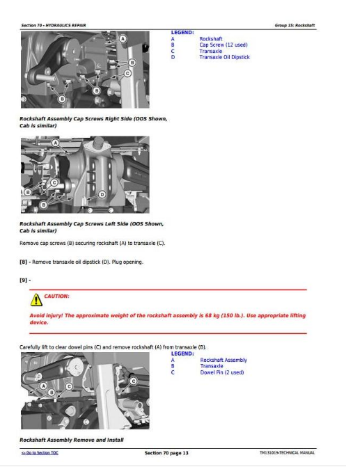
Rockshaft Removal and Installation
SCV Control Cable Removal and Installation
Third SCV Removal and Installation342200224Cab
Third SCV Removal and Installation342200224OOS
Three Point Hitch Removal and Installation
80 - Miscellenous Repair
Grille Removal and Installation
Hood Removal and Installation
Rear Fenders Removal and Installation (Cab)
Rear Fenders Removal and Installation (Open Station)
Side Panel Removal and Installation
Wheel Removal and Installation342200224Front
Wheel Removal and Installation342200224Rear
90 - Cab_Operator's Station Repair
Air Conditioning Evaporator Removal and Installation
Air Conditioning Receiver-Dryer Removal and Installation
Blower Motors Removal and Installation
Cab Door Removal and Installation
Cab Outer Roof Removal and Installation
Cab Removal and Installation
Center Console Pedestal Removal and Installation (Open Station)
Charge Air Conditioning System
Cleaning Cab Air Filter
Compressor Clutch Disassemble and Assemble
Compressor Disassemble, Inspect, and Assemble
Control Panel Removal and Installation (Cab)
Control Panel Removal and Installation (Open Station)342200224Hydrostatic Transmission
Control Panel Removal and Installation (Open Station)342200224PowrReverser Transmission
Cowl Panel Removal and Installation (Cab)
Cowl Panel Removal and Installation (Open Station)
Evacuate Air Conditioning System
Flush Air Conditioning System
Foot Deck Removal and Installation (Open Station)342200224Hydrostatic Transmission
Foot Deck Removal and Installation (Open Station)342200224PowrReverser Transmission
Foot Throttle Removal and Installation (Open Station)342200224PowrReverser Transmission
Headliner Removal and Installation
Heater Control Valve Removal and Installation
Heater Core Removal and Installation
Left Side Control Console Removal and Installation
Remove, Inspect, and Install Air Conditioning Compressor
Remove, Inspect, and Install Air Conditioning Condenser
Right Side Control Console Removal and Installation
Roll Over Protection System (ROPS) Removal and Installation (Open Station)
Seat and Support Removal and Installation (Cab)
Seat and Support Removal and Installation (Open Station)
Seat Closeout Removal and Installation (Open Station)342200224Hydrostatic Transmission
Seat Closeout Removal and Installation (Open Station)342200224PowrReverser Transmission
Service Expansion Valve
Servicing Air Conditioner Belt (Cab)
Temperature Control Cable Removal and Installation
Temperature Control Removal and Installation
John Deere 4044M, 4044R, 4049M, 4049R, 4052M, 4052R, 4066M, 4066R Tractors Diagnostic and Repair Service Manual (TM131019)
![]()