
John Deere 3032E, 3036E, 3038E Compact Utility Tractors Service Technical Manual (TM100619)
All Inclusive Diagnosis, Operation, Tests, Repair & Service manual with electrical wiring diagrams for John Deere Compact Utility Tractors Models 3032E, 3036E and 3038E (S.N. 010001-60999), with all the shop information to maintain, diagnose, repair, and service like professional mechanics.
Total Pages: 1,096 pages
File Format: PDF/EPUB/MOBI/AZW (PC/Mac/Android/Kindle/iPhone/iPad; bookmarked, ToC, Searchable, Printable)
Language: English
TM100619 - John Deere Compact Utility Tractors Models 3032E, 3036E and 3038E (S.N. 010001-60999) Tractors All Inclusive Technical Service Manual (Diagnostic & Repair).PDF
TM100619 - John Deere Compact Utility Tractors Models 3032E, 3036E and 3038E (S.N. 010001-60999) Tractors All Inclusive Technical Service Manual (Diagnostic & Repair).EPUB
MAIN SECTIONS
Foreword
Safety
Safety
Specifications and Information
General Specifications
Fuel and Lubricants
Serial Number Locations
Engine-Diesel
Specifications
Component Location
Theory of Operation
Diagnostics
Tests and Adjustments
Repair
Electrical
General Information
Specifications
Component Location
Schematics and Harnesses
Operation and Diagnostics
Tests and Adjustments
Repair
Export Electrical
Component Location
Schematics and Harnesses
Operation and Diagnostics
Power Train
Specifications
Component Location
Theory of Operation
Diagnostics
Troubleshooting
Tests and Adjustments
Repair
Hydraulics
Specifications
Component Location and Schematics
Theory of Operation
Troubleshooting
Tests and Adjustments
Repair
Steering
Specifications
Component Location
Theory of Operation
Diagnostics
Tests and Adjustments
Repair
Brakes
Specifications
Component Location
Theory of Operation
Diagnostics
Tests and Adjustments
Repair
Miscellaneous
Specifications
Component Location
Repair
TABLE OF CONTENTS (exploded view)
10 - General Information
05 - Safety
Avoid Harmful Asbestos Dust
Avoid Heating Near Pressurized Fluid Lines
Avoid High-Pressure Fluids
Dispose of Waste Properly
Handle Chemical Products Safely
Handle Fluids Safely342200224Avoid Fires
Illuminate Work Area Safely
Live With Safety
Park Machine Safely
Prepare for Emergencies
Prevent Acid Burns
Prevent Battery Explosions
Protect Against High Pressure Spray
Recognize Safety Information
Remove Paint Before Welding or Heating
Replace Safety Signs
Service Cooling System Safely
Service Machines Safely
Service Tires Safely
Stay Clear of Rotating Drivelines
Support Machine Properly
Understand Signal Words
Use Proper Lifting Equipment
Use Proper Tools
Wear Protective Clothing
Work in Clean Area
Work In Ventilated Area
20 - Specifications and Information
05 - Genearl Specifications
Gasket Sealant Application
Metric Bolt and Screw Torque Values
Metric Cap Screw Torque Values342200224Grade 7
Service Recommendations For Flat Face O-Ring Seal Fittings
Service Recommendations for O-Ring Boss Fittings
Unified Inch Bolt and Screw Torque Values
10 - Fuels and Lubricants
Alternative and Synthetic Lubricants
Diesel Engine Break-In Oil
Diesel Engine Oil
Diesel Fuel
Grease
Heavy Duty Diesel Engine Coolant
Lubricant Storage
Mixing of Lubricants
Transmission and Hydraulic Oil
15 - Machine Specifications
Engine Serial Number
Machine Product Identification Number
Serial Numbers
25 - Diagnostic Trouble Codes
05 - General References
10 - Instrument Cluster Control (ICC) DTC
15 - Engine Control Unit (ECU) DTC
30 - Engine - Diesel
05 - Specifications
General Specifications
Operational Tests
Other Materials
Repair Specifications
Service Equipment and Tools
Tests and Adjustment Specifications
Torque Values, Non-Standard Fasteners
10 - Component Location
Air Cleaner and Intake Components
Fuel Supply Components
Turbocharger Components
15 - Theory of Operation
Air Intake System
Cooling System Operation
Fuel System Operation
Lubrication System Operation
Turbocharger Operation
20 - Diagnostics
Check for Head Gasket Failures
Coolant in Oil or Oil in Coolant
Coolant Temperature Abnormal
Diagnostic Table
Engine Oil Diagnostics
Engine Oil Pressure Low
Engine Operation Poor
Engine Starting Problem
Engine Troubleshooting
Excessive Fuel Consumption
Incorrect Manifold Pressure
Low Engine Compression
Turbocharger Failure Analysis
25 - Tests and Adjustments
Bleed Fuel System
Camshaft End Play Check
Check Air Intake System
Check for Excessive Engine Crankcase Pressure (Turbocharged Engines)
Check for Exhaust Air Leaks (Turbocharger)
Check for Intake and Exhaust Restrictions
Connecting Rod Bearing Clearance Check
Connecting Rod Side Play Check
Cooling System Pressure Test
Crankshaft End Play Check
Crankshaft Main Bearing Clearance Check
Cylinder Compression Test
Engine Oil Pressure Test
Fan and Alternator Drive Belt Adjustment
Fuel Injection Nozzle Test
Fuel Supply Pump Pressure Test
Fuel System Leakage Test
Injection Pump Timing
Radiator Bubble Test
Radiator Pressure Cap Test
Slow Idle Adjustment
Thermostat Opening Test
Throttle Rod Adjustment
Timing Gear Backlash Check
Turbocharger Inspection
Turbocharger Oil Seal Leak Check
Turbocharger Waste Gate Test
Valve Clearance Adjustment
Valve Lift Check
30 - Repair
Camshaft Followers
Camshaft
Crankshaft and Main Bearings
Crankshaft Front Oil Seal
Crankshaft Rear Oil Seal
Cylinder Bore
Cylinder Head and Valves Disassembly and Assembly
Cylinder Head and Valves Removal and Installation
Engine and Flywheel Housing Split
Engine Removal and Installation
Exhaust Manifold
Flywheel and Coupling
Fuel Filter and Water Separator
Fuel Injection Nozzles
Fuel Injection Pump
Glow Plug Removal and Installation (3032E)
Grind Valve Seats
Idler Gear
Intake Manifold
Lap Valves
Measure Piston-To-Cylinder Head Clearance
Muffler Removal and Installation
Oil Pan and Strainer
Oil Pump
Piston and Connecting Rod
Piston Inspection
Radiator Removal and Installation
Rocker Arm Assembly
Rocker Cover Removal and Installation
Starting Motor Removal and Installation
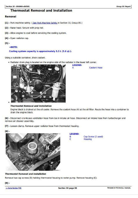
Thermostat Removal and Installation
Timing Gear Cover Mounting Plate
Timing Gear Cover
Turbocharger Removal and Installation
Valve Guides
Valve Recession
Valve Seats
Valve Springs
Water Pump Removal and Installation
40 - Electrical
05 - General Information
Common Circuit Tests
Conductors For 12 Volt Circuits
Diagnostic Information
Reading Electrical Schematics
Theory Of Operation Information
Wire Color Abbreviation Chart
10 - Specifications
Other Materials
Service Equipment and Tools
Specifications
15 - Component Location
Control Panel
Cruise Control Components
Electrical Components
Load Center
20 - Schematic and Wiring Harness
Cruise Control Harness Color Codes
Cruise Control Schematic
Main Schematic
Schematic and Wiring Harness Legend
W1 Main Wiring Harness Color Codes
W1 Main Wiring Harness
W2 Cruise Control Wiring Harness
25 - Operation and Diagnostics
Charging Circuit Diagnosis
Charging Circuit Schematic
Charging Circuit Theory of Operation
Cranking Circuit Diagnosis
Cranking Circuit Theory of Operation
Cranking, Glow Plug, and Fuel Circuit Schematic
Cruise Control Circuit Diagnosis
Cruise Control Circuit Schematic
Cruise Control Circuit Theory of Operation
Display Panel Circuit Diagnosis
Display Panel Circuit Schematic
Display Panel Theory of Operation
Fuel Supply Circuit Theory of Operation
Glow Plug Circuit Theory of Operation
Lighting Circuit Schematic
Lighting Circuit Theory of Operation
Power Circuit Schematic
Power Circuit Theory of Operation
PTO Circuit Diagnosis
PTO Circuit Operation
PTO Circuit Schematic
30 - Tests and Adjustments
Alternator Regulated Voltage Test
Battery342200224Charge
Battery342200224Load Test
Battery Voltage and Specific Gravity Test
Brake Switch Test
Cruise Control Magnet Test
Cruise Control Switch Test
Engine Coolant Temperature Sensor Test
Engine Oil Pressure Switch Test
Fuel Shutoff Solenoid Test
Fuse Test
Glow Plug Test
Ground Circuit Test
Hazard Switch Test
Horn Switch Test
Key Switch Test
Light Switch Test
Manifold Heater Test
Miniature Relay Test
PTO Solenoid Test
Rear PTO Switch Test
Regulated Amperage and Voltage Test
Relay Test
Seat Switch Test
Sensing Switch Test
Starting Motor Amperage Draw Test
Starting Motor No-Load Amperage Draw and RPM Test
Starting Motor Solenoid Test
Turn Signal Switch Test
35 - Repair
Alternator Disassembly and Assembly
Alternator Removal and Installation
Starting Motor Disassembly and Assembly
Starting Motor Inspection_Test
45 - Export Electrical
05 - Component Location
Control Panel
Electrical Components
Load Center
10 - Schematic and Wiring Harness
Main Schematic
Schematic and Wiring Harness Legend
W1 Main Wiring Harness Color Codes
W1 Main Wiring Harness
15 - Operations and Diagnostics
Charging Circuit Diagnosis
Charging Circuit Electrical Schematic
Charging Circuit Operation
Cranking Circuit Diagnosis
Cranking Circuit Electrical Schematic
Cranking Circuit Theory of Operation
Cruise Control Circuit Diagnosis
Cruise Control Circuit Schematic
Cruise Control Circuit Theory of Operation
Display Panel Circuit Diagnosis
Display Panel Circuit Electrical Schematic
Display Panel Theory of Operation
Fuel and Safety Circuit Diagnosis
Fuel and Safety Circuit Electrical Schematic
Fuel and Safety Circuit Operation
Glow Plug and Manifold Heater Circuit Diagnosis
Glow Plug Circuit Schematic
Glow Plug Circuit Theory of Operation
Lights and Horn Circuit Diagnosis
Lights and Horn Circuit Operation
Lights and Horn Circuit Schematic
Power Circuit Diagnosis
Power Circuit Electrical Schematic
Power Circuit Theory of Operation
PTO and Safety Circuit Diagnosis
PTO and Safety Circuit Electrical Schematic
PTO and Safety Circuit Operation
50 - Power Train
05 - Specifications
General Specifications
Other Material
Repair Specifications
Service Equipment and Tools
Torque Specifications
10 - Component Location
Axle Housing
Brake and Axle Housing
Brake and Differential Lock Linkage
Differential Assembly
Drive Pedals and Linkage
Front Drive (For MFWD)
MFWD Front Axle Housing and Differential
Pinion Shaft
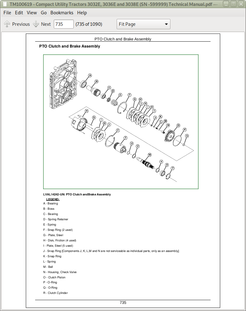
PTO Clutch and Brake Assembly
PTO Rear Shaft
Rear Axle and Final Drive
Transmission and Swash Plate
Transmission Housing
Transmission Oil Pump
15 - Theory of Operation
Differential Power Flow and Lock
MFWD Power Operation
Power Transmission - Rear PTO
Range Transmission
20 - Diagnostics
Final Drive Diagnosis
System Checks
25 - Troubleshooting
Differential Lock
Final Drive Symptom Diagnosis
General Operation
PTO Diagnostics
Symptom Diagnosis
30 - Tests and Adjustments
Charge Pump Pressure Test and Adjustment
Control Pedal Adjustment
Differential Backlash Adjustment
Differential Pinion Shaft Adjustment
35 - Repair
Axle Housing Disassembly and Assembly
Differential Removal and Installation
Hydraulic Gear Pump and Drive Removal
Hydraulic Gear Pump Removal
Machine Splitting (Front)
Machine Splitting (Rear)
MFWD Differential
MFWD Final Drive Cover
MFWD Output Assembly
MFWD Removal and Installation
MFWD Spindle Shaft
PTO Clutch Disassembly and Assembly
PTO Clutch Removal and Installation
PTO Drive Shaft and Gears
Rear Axles
Speed Range Gears
60 - Hydraulics
05 - Specifications
Hydraulic Specifications
Service Equipment and Tools
Torque Specifications
10 - Component Location and Schematics
PTO System Schematics
Rockshaft and Lift Arms
Rockshaft and SCV System Schematics
Rockshaft Control Valve
Steering System Components
Steering System Schematic
15 - Theory of Operation
Hydraulic Operation
PTO Clutch and Brake Theory of Operation
Rockshaft Operation
20 - Troubleshooting
Hydrostatic Troubleshooting
Rockshaft Hydraulics
25 - Tests and Adjustments
Charge Pressure Test
Hydraulic System Bleed Procedure
Lift Arms Adjustment
PTO Clutch Pressure Test
Rate of Drop and Stop Valve Adjustment
Rockshaft Leakage Test
Rockshaft Lift Cycle Test
Rockshaft Position Feedback Linkage Adjustment
Rockshaft Surge Relief Test
Steering Pressure Test
System Pressure Adjustment
System Pressure and Flow Test
30 - Repair
Hydraulic Gear Pump and Reduction
Rockshaft Disassembly and Assembly
Rockshaft Lift Arms Removal and Installation
Rockshaft Removal and Installation
70 - Steering
05 - Specifications
Service Equipment and Tools
Steering Specifications
Torque Specifications
10 - Component Location and Schematics
Steering Components
Steering System Schematic
15 - Theory of Operation
Steering
20 - Troubleshooting
Symptom Steering Noisy or Vibrates
Symptom Steering Problems
System Steering Checks
25 - Tests and Adjustments
Steering Pressure Check
Steering System Test
Toe-in Adjustment MFWD
30 - Repair
Steering Control Unit (SCU) Removal and Installation
Steering Cylinder Removal and Installation MFWD
Steering Wheel Removal and Installation
Tie Rod Removal and Installation MFWD
80 - Brakes
05 - Specifications
Brakes
Torque Specifications
10 - Component Location
Brake Assembly
Brake Pedal and Linkage (Exploded View)
Brake Pedal and Linkage
15 - Theory of Operation
Brakes
20 - Troubleshooting
Brakes
Diagnostic Check Points
25 - Tests and Adjustments
Brake and Differential Lock Adjustment
30 - Repair
Brake Assembly
Brake Pedal Assembly Removal and Installation
90 - Miscellaneous
05 - Specifications
General Specifications
Torque Specifications
10 - Component Location
Fuel Tank and Firewall
15 - Repair
Battery Removal and Installation
Control Panel Removal and Installation
Front Wheel Removal and Installation
Fuel Tank Removal and Installation
Hood Removal and Installation
Operator342200231s Foot Decks
Rear Fenders Removal and Installation
Rear Wheel Removal and Installation
Roll Over Protection System (ROPS)
Seat and Seat Support Removal and Installation
John Deere 3032E, 3036E, 3038E Compact Utility Tractors Service Technical Manual (TM100619)
![]()