
John Deere Compact Utility Tractors Models 3032E, 3036E, 3038E Service Technical Manual (TM127919)

All Inclusive Diagnosis, Operation, Tests, Repair Service manual with electrical wiring diagrams for John Deere Compact Utility Tractors Models 3032E, 3036E, and 3038E (SN. from 610000), with workshop information to maintain, diagnose, repair, and service like professional mechanics.
TM127919 - John Deere 3032E, 3036E, 3038E (SN.610000-) Tractors All Inclusive Technical Service Manual (Diagnostic & Repair) (August 2014).pdf
TM127919 - John Deere 3032E, 3036E, 3038E (SN.610000-) Tractors All Inclusive Technical Service Manual (Diagnostic & Repair) (August 2014).epub
Total Pages: 1,454 pages
File Format: PDF/EPUB/MOBI/AZW (PC/Mac/Android/Kindle/iPhone/iPad; bookmarked, ToC, Searchable, Printable)
Language: English
MAIN SECTIONS
Foreword
Safety
Safety
Specifications and Information
General Specifications
Fuel and Lubricants
Serial Number Locations
Diagnostic Trouble Codes
General References
Instrument Cluster Control (ICC) Diagnostic Trouble Codes
Engine Control Unit (ECU) Diagnostic Trouble Codes
Engine-Diesel
Specifications
Component Location
Theory of Operation
Diagnostics
Tests and Adjustments
Repair
Electrical
General Information
Specifications
Component Location
Schematics and Harnesses
Operation and Diagnostics
Tests and Adjustments
Repair
Electrical - 3036E
Component Location
Schematics and Harnesses
Operation and Diagnostics
Electronic Control Units
General References
Theory of Operation
Programing and Calibrations
Test and Adjustments
Diagnostic Addresses
Power Train
Specifications
Component Location
Theory of Operation
Diagnostics
Troubleshooting
Tests and Adjustments
Repair
Hydraulics
Specifications
Component Location and Schematics
Theory of Operation
Troubleshooting
Tests and Adjustments
Repair
Steering
Specifications
Component Location
Theory of Operation
Diagnostics
Tests and Adjustments
Repair
Brakes
Specifications
Component Location
Theory of Operation
Diagnostics
Tests and Adjustments
Repair
Miscellaneous
Specifications
Component Location
Repair
tm127919 - 3025E, 3032E, 3036E, and 3038E Compact Utility Tractors Diagnostic and Repair Manual
Table of Contents
Foreword
Section 10: General Information
Group 05A: Safety
Recognize Safety Information
Understand Signal Words
Follow Safety Instructions
Prepare for Emergencies
Wear Protective Clothing
Protect Against Noise
Handle Fuel Safely—Avoid Fires
Handle Starting Fluid Safely
Fire Prevention
In Case of Fire
Keep ROPS Installed Properly
Use Foldable ROPS and Seat Belt Properly
Stay Clear of Rotating Drivelines
Use Steps and Handholds Correctly
Read Operator’s Manuals for ISOBUS Controllers
Use Seat Belt Properly
Operating the Tractor Safely
Avoid Backover Accidents
Limited Use in Forestry Operation
Operating the Loader Tractor Safely
Keep Riders Off Machine
Instructional Seat
Use Safety Lights and Devices
Use a Safety Chain
Transport Towed Equipment at Safe Speeds
Towing Trailers/Implements Safely
Use Caution on Slopes, Uneven Terrain, and Rough Ground
Freeing a Mired Machine
Avoid Contact with Agricultural Chemicals
Handle Agricultural Chemicals Safely
Handling Batteries Safely
Avoid Heating Near Pressurized Fluid Lines
Remove Paint Before Welding or Heating
Handle Electronic Components and Brackets Safely
Practice Safe Maintenance
Avoid Hot Exhaust
Clean Exhaust Filter Safely
Work In Ventilated Area
Support Machine Properly
Prevent Machine Runaway
Park Machine Safely
Transport Tractor Safely
Service Cooling System Safely
Service Accumulator Systems Safely
Service Tires Safely
Service Front-Wheel Drive Tractor Safely
Tightening Wheel Retaining Bolts/Nuts
Avoid High-Pressure Fluids
Do Not Open High-Pressure Fuel System
Store Attachments Safely
Decommissioning — Proper Recycling and Disposal of Fluids and Components
Group 05B: General References
Deliver Safely
Information Available in Sections, Groups and Subgroups
Glossary of Terms
Trademarks
Group 05C: Technical Specific References
Metric Bolt and Screw Torque Values
Unified Inch Bolt and Screw Torque Values
Metric Cap Screw Torque Values—Grade 7
Gasket Sealant Application
Service Recommendations For Flat Face O-Ring Seal Fittings
Service Recommendations for O-Ring Boss Fittings
Group 05D: Fuel and Lubricants
Diesel Fuel
Handling and Storing Diesel Fuel
Diesel Engine Oil
Diesel Engine Break-In Oil
Alternative and Synthetic Lubricants
Lubricant Storage
Mixing of Lubricants
Grease
Transmission and Hydraulic Oil
Diesel Engine Coolant (engine with wet sleeve cylinder liners)
Group 05E: Serial Number Locations
Serial Numbers
Machine Product Identification Number
Engine Serial Number
Section 20: Engine Repair
Group 05: Engine
Glow Plug Removal and Installation
Rocker Cover Removal and Installation
Rocker Arm Assembly
Engine Removal and Installation
Cylinder Head and Valves Removal and Installation
Cylinder Head and Valves Disassembly and Assembly
Valve Seats
Valve Recession
Valve Guides
Valve Springs
Grind Valve Seats
Lap Valves
Measure Piston-To-Cylinder Head Clearance
Piston and Connecting Rod
Piston Inspection
Cylinder Bore
Crankshaft Front Oil Seal
Crankshaft Rear Oil Seal
Crankshaft and Main Bearings
Flywheel and Coupling
Camshaft
Camshaft Followers
Timing Gear Cover
Idler Gear
Timing Gear Cover Mounting Plate
Oil Pan and Strainer
Oil Pump
Group 10: Cooling System
Radiator Removal and Installation—3036E
Radiator Removal and Installation—3032E, 3038E
Thermostat Removal and Installation
Water Pump Removal and Installation
Section 30: Fuel, Air Intake, and Exhaust Repair
Group 05: Fuel
Fuel Filter and Water Separator
Secondary Fuel Filter
Fuel Injection Pump
Fuel Injection Nozzles
Fuel Tank Removal and Installation
Group 10: Air Intake
Intake Manifold
Group 20: Exhaust
Muffler Removal and Installation
Diesel Particulate Filter Removal and Installation
Exhaust Pipe Removal and Installation-Downward Exhaust
Exhaust Pipe Removal and Installation-Vertical Exhaust
Turbocharger Removal and Installation
Exhaust Manifold
Section 40: Electrical Repair
Group 05: Battery, Starter and Alternator
Battery Removal and Installation
Starting Motor Removal and Installation
Starting Motor Disassembly and Assembly
Starting Motor Inspection/Test
Alternator Removal and Installation
Alternator Disassembly and Assembly
Group 10: Electrical System Components
Engine Control Unit (ECU) Removal and Installation
Section 50: Drive System and Transmissions Repair
Group 05: Separation
Machine Splitting (Rear)
Machine Splitting (Front)
Group 10: Power Train
Speed Range Gears
Group 15: MFWD
MFWD Output Assembly
MFWD Removal and Installation
MFWD Final Drive Cover
MFWD Spindle Shaft
MFWD Differential (—Oct 2013)
MFWD Differential (Oct 2013— )
Group 20: Differential
Rear Axles
Axle Housing Disassembly and Assembly
Differential Removal and Installation
Group 25: PTO
PTO Drive Shaft and Gears
PTO Clutch Removal and Installation
PTO Clutch Disassembly and Assembly
Section 60: Steering and Brake Repair
Group 05: Steering
Steering Cylinder Removal and Installation MFWD
Steering Wheel Removal and Installation
Steering Control Unit (SCU) Removal and Installation
Tie Rod Removal and Installation MFWD
Group 10: Brake
Power Train Brake Assembly
Brake Pedal Assembly Removal and Installation
Brake Assembly
Section 70: Hydraulics Repair
Group 05: Hydraulic Pump and Filter
Hydraulic Gear Pump Removal
Hydraulic Gear Pump and Drive Removal
Hydraulic Gear Pump and Reduction
Group 10: Rockshaft
Rockshaft Removal and Installation
Rockshaft Disassembly and Assembly
Rockshaft Lift Arms Removal and Installation
Section 80: Miscellaneous Repair
Group 05: Hood and Side Panels
Hood Removal and Installation
Group 10: Fenders
Rear Fenders Removal and Installation
Group 15: Wheels
Front Wheel Removal and Installation
Rear Wheel Removal and Installation
Section 90: Operator’s Station Repair
Group 05: Seat and Support
Seat and Seat Support Removal and Installation
Group 10: Control Console
Control Panel Removal and Installation
Group 15: Roll-Gard
Roll Over Protection System (ROPS)
Group 20: Operator Station Components
Operator’s Foot Decks
Section 211: Diagnostic Trouble Codes
Group 05: General References
Diagnostic Trouble Codes - Summary of References
Diagnostic Trouble Codes Overview
Recall, Record, and Clear Codes
Erroneous Diagnostic Trouble Codes
Group ICC: Instrument Cluster Control (ICC) Diagnostic Trouble Codes
ICC 000000.00-999999.99 - ICC Diagnostic Trouble Codes
Group ECU: Engine Control Unit (ECU) Diagnostic Trouble Codes
ECU - Non-Tractor ECU Codes
ECU 000000.00-999999.99 - ECU Diagnostic Trouble Codes
Section 212: Observable Symptoms and System Diagnostics
Group 05: General References
Observable Symptoms and System Diagnostics - Summary of References
Group 20: Engine System Diagnostics
Engine Diagnosis
Group 30: Fuel, Air Intake, Exhaust, and Cooling System Diagnostics
Fuel and Air System Diagnosis
Group 40: Electrical System Diagnostics
Starting System Diagnosis
Charging System Diagnosis
Group 45: Electronic Control Unit System Diagnostics
CAN System Diagnosis
Group 50: Drive Systems and Transmission System Diagnostics
MFWD System Diagnosis
Power Train System Diagnosis
Differential Lock System Diagnosis
Rear PTO System Diagnosis
Group 60: Steering and Brakes System Diagnostics
Rear Brake System Diagnosis
Steering System Diagnosis
Group 70: Hydraulic System Diagnostics
Hydraulic System Diagnosis
SCV / Hitch System Diagnosis
Section 220: Engine Operation, Test, and Adjustments
Group 05: General References
Engine Operation, Test and Adjustments—Summary of References
Engine Information
Install Test Equipment 20-1
Install Test Equipment 20-2
Group 10: Calibrations, Preliminary Checks and Operational Checks
Engine—Preliminary Checks
Engine—Operational Checks
Group 20: Theory of Operation
Lubrication System Theory of Operation
Group 50: Tests and Adjustments
Fan and Alternator Drive Belt Adjustment
Cylinder Compression Test
Cylinder Leakage Test
Valve Clearance Adjustment
Valve Lift Check
Engine Oil Pressure Test
Engine Oil Consumption
Crankshaft End Play Check
Timing Gear Backlash Check
Camshaft End Play Check
Connecting Rod Side Play Check
Connecting Rod Bearing Clearance Check
Crankshaft Main Bearing Clearance Check
Section 230: Fuel , Air Intake, Exhaust, and Cooling Operation, Test, and Adjustments
Group 05: General References
Fuel, Air Intake, Exhaust, and Cooling Operation, Test, and Adjustments—Summary of References
Install Test Equipment 30-1
Install Test Equipment 30-2
Group 10: Calibrations, Preliminary Checks and Operational Checks
Air Intake Operational Checks
Cooling Operational Checks
Fuel Operational Checks
Turbocharger Operational Checks
Group 20: Theory of Operation
Fuel System Theory of Operation
Cooling System Theory of Operation
Air Intake System Theory of Operation
Turbocharger Theory of Operation
Group 40: Component and Connector Information
Air Cleaner and Intake Component Overview—3025E
Air Cleaner and Intake Component Overview—3032E
Air Cleaner and Intake Component Overview—3036E
Air Cleaner and Intake Component Overview—3038E
Fuel Supply Component Overview—3025E
Fuel Supply Component Overview—3032E and 3038E
Fuel Supply Component Overview—3036E
Turbocharger Component Overview
Group 50: Tests and Adjustments
Check Air Intake System
Check for Intake and Exhaust Restrictions
Throttle Rod Adjustment
Slow Idle Adjustment
Fuel System Leakage Test
Bleed Fuel System
Fuel Pump Supply Pressure Test
Injection Pump Timing
Fuel Injection Nozzle Test
Check for Exhaust Air Leaks (Turbocharger)
Turbocharger Oil Seal Leak Check
Turbocharger Waste Gate Test
Turbocharger Inspection
Cooling System Pressure Test
Radiator Cap Pressure Test
Thermostat Opening Test
Section 240A: Electrical General and Theory of Operation
Group 05: General References
Electrical General and Theory of Operation - Summary of References
Electrical Designators
Electrical Procedure
Circuit Malfunctions
Circuit Types
Relay Circuit Types
Electrical Schematic Symbols
Reading Wiring Functional Schematics
Wiring Diagram and Schematic Information
Troubleshooting Unresolved Electrical/Electronic Problems
Visually Inspect Electrical System
Using a Probe Light
Using a Digital Multimeter
Group 20A: Key Switch, Starter and Alternator Theory of Operation
Cranking Circuit Theory of Operation
Glow Plug Circuit Theory of Operation
Charging Circuit Theory of Operation
Power Circuit Theory of Operation
Group 20B: Instrument Cluster Control (ICC) Theory of Operation
Instrument Cluster Control (ICC) Theory of Operation
PTO Circuit Theory of Operation
Group 20C: Engine Control Unit (ECU) Theory of Operation
Fuel Supply Circuit Theory of Operation
Group 20D: Lights, Turn Signals, Cruise Control Theory of Operation
Lighting Circuit Theory of Operation
Cruise Control Circuit Theory of Operation
Section 240B: Electrical Schematics
Group 05: General References
Electrical Schematics - Summary of References
Group 30AA: Key Switch, Starter and Alternator—with ECU (SE1A)
Key Switch, Starter and Alternator—with ECU Schematic (SE1A)
Group 30AB: Key Switch, Starter and Alternator—without ECU (SE1B)
Key Switch, Starter and Alternator—without ECU Schematic (SE1B)
Group 30BA: Instrument Cluster Control—with ECU (SE2A)
Instrument Cluster Control—with ECU Schematic (SE2A)
Group 30BB: Instrument Cluster Control—without ECU (SE2B)
Instrument Cluster Control—without ECU Schematic (SE2B)
Group 30CA: Engine Control Unit (ECU)—3032E, 3038E (SE3A)
Engine Control Unit (ECU) Schematic—3032E, 3038E (SE3A)
Group 30CB: Engine Control Unit (ECU)—3025E (SE3B)
Engine Control Unit (ECU) Schematic—3025E (SE3B)
Group 30DA: Lights and Turn Signals—with ECU (SE4A)
Lights and Turn Signals—with ECU Schematic (SE4A)
Group 30DB: Lights and Turn Signals—with ECU (SE4B)
Lights and Turn Signals—without ECU Schematic (SE4B)
Group 30EA: Cruise Control (SE5)
Cruise Control Schematic (SE5)
Group 30FA: Electrical Harness Diagrams
W100 Chassis Harness Diagram—3032E, 3038E
W101 Chassis Harness Diagram—3025E
W102 Chassis Harness Diagram—3036E
W200 Cruise Control Harness Diagram
Section 240C: Electrical Components and Connectors
Group 05: General References
Electrical Components and Connectors - Summary of References
Group 40AA: Key Switch, Starter and Alternator—with ECU (SE1A)
F21 Inline Fuse (250A)—with ECU
F22 Alternator Fuse
F23 Load Center Fuse
F24 Glow Plugs Fuse
G01 Battery—with ECU
G02 Alternator—with ECU
K02 Starter Relay—with ECU
K03 Glow Plug Relay—with ECU
M01 Starter Motor—with ECU
M02 Fuel Pump Motor—with ECU
R01 Glow Plug—with ECU
R02 Glow Plug—with ECU
R03 Glow Plug—with ECU
S01 Key Switch—with ECU
Group 40AB: Key Switch, Starter and Alternator—without ECU (SE1B)
G01 Battery—without ECU
G02 Alternator—without ECU
M01 Starter Motor—without ECU
R01 Glow Plug—without ECU
R02 Glow Plug—without ECU
R03 Glow Plug—without ECU
S01 Key Switch—without ECU
Group 40BA: Instrument Cluster Control—with ECU (SE2A)
A01 Instrument Cluster Control (ICC)
A01-J1 Instrument Cluster Control (ICC) Connector—with ECU
A01-J2 Instrument Cluster Control (ICC) Connector—with ECU
A01-J3 Instrument Cluster Control (ICC) Connector—with ECU
B04 Engine Oil Pressure Switch—with ECU
S03 Turn Signal Switch—with ECU
S04 Transmission Neutral Switch—with ECU
S05 PTO Switch—with ECU
S38 Seat Switch—with ECU
S39 Park Brake Switch
S47 Roll/Display Mode Switch
X19 Service Advisor Connector
Group 40BB: Instrument Cluster Control—without ECU (SE2B)
A01 Instrument Cluster Control (ICC)—without ECU
A01-J1 Instrument Cluster Control (ICC) Connector—without ECU
A01-J2 Instrument Cluster Control (ICC) Connector—without ECU
A01-J3 Instrument Cluster Control (ICC) Connector—without ECU
B02 Engine Coolant Temp Switch—without ECU
B04 Engine Oil Pressure Switch—without ECU
S04 Transmission Neutral Switch—without ECU
S05 PTO Switch—without ECU
S38 Seat Switch—without ECU
Y02 Fuel Shutoff Solenoid—without ECU
Y03 Rear PTO Solenoid—without ECU
Group 40CA: Engine Control Unit (ECU)—3032E, 3038E (SE3A)
ECU—3032E, 3038E
ECU-J1 Connector—3032E, 3038E
ECU-J2 Connector—3032E, 3038E
F08 Inline Fuse (10A)—with ECU
B12 DPF Inlet Temperature Sensor
B13 DPF Intermediate Temperature Sensor
B14 DPF Differential Pressure Switch
P03 Hand Throttle Switch—3032E, 3038E
S48 DPF Regeneration Switch
Group 40CB: Engine Control Unit (ECU)—3025E (SE3B)
ECU—3025E
ECU Connector—3025E
B10 Throttle Sensor
B11 Coolant Temperature Sensor
B15 Revolution Sensor
K27 Main Battery Relay
Y05 EGR Valve
Y06 Rack Actuator
Y08 Cold Start Device
Group 40DA: Lights and Turn Signals—with ECU (SE4A)
E01 LH Headlight—with ECU
E02 RH Headlight—with ECU
E03 Left Tail/Turn/Warning Light—with ECU
E04 Right Tail/Turn/Warning Light—with ECU
E05 LH Work Light—with ECU
E06 RH Work Light—with ECU
S02 Light Switch—with ECU
Group 40DB: Lights and Turn Signals—Without ECU (SE4B)
E01 LH Headlight—Without ECU
E02 RH Headlight—Without ECU
E05 LH Work Light—Without ECU
E06 RH Work Light—Without ECU
E07 Right Front Turn Signal, Tail Light, and Hazard Light—Without ECU
E11 Left Rear Turn Signal and Hazard Light—Without ECU
E13 Left Front Turn Signal, Tail Light, and Hazard Light—Without ECU
E16 Right Rear Turn Signal and Hazard Light—Without ECU
E18 License Plate Light—Without ECU
H02 Horn
S02 Light Switch—Without ECU
S07 Turn Signal Switch—Without ECU
S11 Horn Switch
S13 Hazard Light Switch—Without ECU
S42 Brake Switch—Without ECU
Group 40EA: Cruise Control (SE5)
K08 Cruise Control Relay
K09 Cruise Control Relay
M03 Cruise Control Magnet
S42 Brake Switch—With ECU
S46 Cruise Control Switch
Group 40ZA: Fuses and Relays
Load Center—3032E, 3038E
Load Center—3025E
Load Center—3036E
Group 40ZB: Ground Points
W01 Chassis Ground
Group 40ZC: Interconnects
X03 Cruise Control Interconnect
Group 40ZD: Harnesses
W100 Chassis Harness Location—3032E, 3038E
W101 Chassis Harness Location—3025E
W102 Chassis Harness Location—3036E
W200 Cruise Control Harness Location
Section 240D: Electrical Tests and Adjustments
Group 05: General References
Electrical Tests and Adjustments - Summary of References
How to Use Electrical Tests and Adjustments Information
Group 50: Tests and Adjustments
Connector Test
Diode Test
Fuse Test
Light Test
Miscellaneous Component Test
Motor Test
Pump Test
Relay Test
Resistor Test
Sensor Test
Solenoid Test
Switch Test
Alternator Circuit Test
Battery Inspection Test
Open Circuit Load Test
CAN Network Voltage Checks
ECU—Engine Control Unit Test
ICC—Instrument Cluster Control Unit Test
Section 245: Electronic Control Units
Group 05: General References
Electronic Control Units—Summary of References
Control Unit Addresses—Access
Entering Diagnostic and Calibration Modes
VIN Security Fault Diagnosis
Servicing Electronic Control Units
Welding Near Electronic Control Units
Keep Electronic Control Unit Connectors Clean
Group 10: Calibrations, Preliminary Checks and Operational Checks
Programming Control Units
Group 20: Theory of Operation
CAN Bus Theory of Operation
CAN Bus Message Structure
Group 40: Component and Connector Information
Control Unit Connectors and Components
Group 50: Test and Adjustments
Troubleshooting Control Unit Programming
Troubleshooting Unresolved Problems
Control Unit Messaging Errors
Troubleshooting Electronic Controllers
CAN Communication Fault Checks
Monitoring CAN Bus Traffic Data
Group ICC: Instrument Cluster Control (ICC)
Diagnostic Addresses—Instrument Cluster Control (ICC)
Instrument Cluster Control (ICC) Configuration and Calibration
Group ECU: Engine Control Unit (ECU)
Diagnostic Addresses—Engine Control Unit (ECU)
Section 250: Drive System and Transmission Operation, Test, and Adjustments
Group 05A: General References
Drive System and Transmission Operation, Test, and Adjustments—Summary of References
Group 10: Calibrations, Preliminary Checks and Operational Checks
Transmission—Preliminary Checks
Transmission—Operational Checks
PTO - Preliminary Checks
PTO - Operational Checks
Differential and MFWD - Preliminary Checks
Differential and MFWD - Operational Checks
Group 20: Theory of Operation
Range Transmission Theory of Operation
Differential Power Flow and Lock Theory of Operation
MFWD Power Theory of Operation
Power Transmission - Rear PTO Theory of Operation
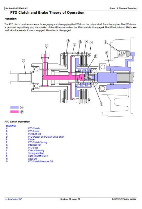
PTO Clutch and Brake Theory of Operation
Group 30: Schematics
Steering System and Hydrostatic Schematic
PTO System Schematic
Group 40: Component and Connector Information
Drive Pedals and Linkage Component Overview
Transmission Oil Pump Component Overview
Transmission and Swash Plate Component Overview
Transmission Housing Component Overview
Drive/Pinion Shaft Component Overview
Differential Assembly Component Overview
Rear Axle and Final Drive Component Overview
PTO Clutch and Brake Assembly Component Overview
PTO Rear Shaft Component Overview
Front Drive Component Overview (For MFWD)
MFWD Front Axle Housing and Differential Component Overview (—OCT 2013)
MFWD Front Axle Housing Component Overview (OCT 2013—)
Differential Component Overview (OCT 2013—)
Axle Housing Component Overview
Axle Housing Component Overview (OCT 2013—)
Group 50: Tests and Adjustments
Control Pedal Adjustment
Charge Pump Pressure Test and Adjustment
Differential Pinion Shaft Adjustment
Differential Backlash Adjustment
PTO Clutch Pressure Test
MFWD Driveline Test
Section 260: Steering and Brakes Operation, Test, and Adjustments
Group 05A: General References
Steering and Brakes Operation, Test, and Adjustments—Summary of References
Group 10A: Calibrations, Preliminary Checks and Operational Checks—Steering
Steering - Preliminary Check
Steering - Operational Check
Group 10B: Calibrations, Preliminary Checks and Operational Checks—Brakes
Brakes - Preliminary Check
Brakes - Operational Check
Group 20A: Theory of Operation—Steering
Steering Theory of Operation
Group 20B: Theory of Operation—Brakes
Brakes Theory of Operation
Group 30A: Schematics—Steering
Steering System Schematic
Group 40A: Component and Connector Information—Steering
Steering Component Overview
Group 40B: Component and Connector Information—Brakes
Brake and Differential Lock Linkage Component Overview
Brake and Axle Housing Component Overview
Brake Pedal and Linkage Component Overview
Brake Assembly Component Overview
Group 50A: Tests and Adjustments—Steering
Steering Pressure Test
Steering Pressure Check
Steering System Test
Toe-in Adjustment MFWD
Group 50B: Tests and Adjustments—Brakes
Brake and Differential Lock Adjustment
Section 270: Hydraulics Operation, Test, and Adjustments
Group 05A: General References
Hydraulics Operation, Test, and Adjustments—Summary of References
Group 10: Calibrations, Preliminary Checks and Operational Checks
Hydraulics - Preliminary Check
Hydraulics - Operational Check
Group 20: Theory of Operation
Hydraulic Theory of Operation
Rockshaft Theory of Operation
Group 30: Schematics
Rockshaft and SCV System Schematic
Group 40: Component and Connector Information
Rockshaft and Lift Arms Component Overview
Rockshaft Control Valve Component Overview
Group 50: Tests and Adjustments
Heating Hydraulic Oil
Hydraulic System Bleed Procedure
Rate of Drop and Stop Valve Adjustment
Lift Arms Adjustment
System Pressure and Flow Test
System Pressure Adjustment
Charge Pressure Test
Rockshaft Lift Cycle Test
Rockshaft Leakage Test
Rockshaft Position Feedback Linkage Adjustment
Rockshaft Surge Relief Test
Section 299: Service Tools
Group 05A: General References
Special Tools - Summary of References
Group 05C: Dealer Fabricated and Service Tools
DFRW20 Compressor Holding Fixture
John Deere Compact Utility Tractors Models 3032E, 3036E, 3038E Service Technical Manual (TM127919)
![]()