
John Deere Compact Utility Tractors Models 3033R, 3038R, 3039R, 3045R, 3046R Service Technical Manual (TM130619)

All Inclusive Technical Manual with Electrical Wiring Diagrams for John Deere 3033R, 3038R, 3039R, 3045R, 3046R Compact Utility Tractors (September 2014), with all the shop information to maintain, diagnose, repair, rebuild like professional mechanics.
John Deere Compact Utility Tractors Models 3033R, 3038R, 3039R, 3045R, 3046R workshop Diagnostics and Repair manual includes:
* Numbered table of contents easy to use so that you can find the information you need fast.
* Detailed sub-steps expand on repair procedure information
* Numbered instructions guide you through every repair procedure step by step.
* Troubleshooting and electrical service procedures are combined with detailed wiring diagrams for ease of use.
* Notes, cautions and warnings throughout each chapter pinpoint critical information.
* Bold figure number help you quickly match illustrations with instructions.
* Detailed illustrations, drawings and photos guide you through every procedure.
* Enlarged inset helps you identify and examine parts in detail.
tm130619 - 3033R, 3038R, 3039R, 3045R and 3046R Compact Utility Tractors Diagnostic and Repair Manual (October 2017) Technical Manual.pdf
Total Pages: 2,647 pages
File Format: PDF/EPUB/MOBI/AZW (PC/Mac/Android/Kindle/iPhone/iPad; bookmarked, ToC, Searchable, Printable)
Language: English
MAIN SECTIONS
Foreword
General Information
Safety
Specifications and Information
General Specifications
Fuel and Lubricants
Serial Number Locations
Diagnostic Trouble Codes
General References
Power Train Hydrostatic (PTH) Control Unit Diagnostic Trouble Codes
Instrument Cluster Control (ICC) Diagnostic Trouble Codes
Engine Control Unit (ECU) Diagnostic Trouble Codes
Engine-Diesel
Specifications
Component Location
Theory of Operation
Diagnostics
Tests and Adjustments
Repair
Electrical - North America
General Information
Specifications
Component Location
Schematics and Harnesses
Operation and Diagnostics
Tests and Adjustments
Electrical - EEC
European Electrical Section
Specifications
Component Location
Schematics and Harnesses
Operation and Diagnostics
Electronic Control Units
General References
Theory of Operation
Programing and Calibrations
Test and Adjustments
Diagnostic Addresses
Power Train-Hydrostatic
Specifications
Component Location
Schematics
Theory of Operation
Diagnostics
Troubleshooting
Tests and Adjustments
Repair
Power Train-PowrReverser
Specifications
Component Location
Theory of Operation
Diagnostics
Troubleshooting
Tests and Adjustments
Repair
Power Train-Final Drive
Specifications
Component Location
Theory of Operation
Diagnostics
Troubleshooting
Final Drive Troubleshooting
Tests and Adjustments
Repair
PTO Theory of Operation
PTO Repair
Hydraulics
Specifications
Component Location
Schematics
Theory of Operation
Troubleshooting
Tests and Adjustments
Repair
Steering
Specifications
Component Location
Theory of Operation
Diagnostics
Tests and Adjustments
Repair
Brakes
Specifications
Component Location
Theory of Operation
Diagnostics
Tests and Adjustments
Repair
HVAC
Specifications
Tools and Materials
General Information
Tests and Adjustments
Miscellaneous
Specifications
Repair
tm130619 - 3033R, 3038R, 3039R, 3045R and 3046R Compact Utility Tractors Diagnostic and Repair Manual (October 2017)
Table of Contents
Foreword
Section 10: General Information
Group 05A: Safety
Recognize Safety Information
Understand Signal Words
Follow Safety Instructions
Prepare for Emergencies
Wear Protective Clothing
Protect Against Noise
Handle Fuel Safely—Avoid Fires
Handle Starting Fluid Safely
Fire Prevention
In Case of Fire
Keep ROPS Installed Properly
Use Foldable ROPS and Seat Belt Properly
Stay Clear of Rotating Drivelines
Use Steps and Handholds Correctly
Read Operator’s Manuals for ISOBUS Controllers
Use Seat Belt Properly
Operating the Tractor Safely
Avoid Backover Accidents
Limited Use in Forestry Operation
Operating the Loader Tractor Safely
Keep Riders Off Machine
Instructional Seat
Use Safety Lights and Devices
Use a Safety Chain
Transport Towed Equipment at Safe Speeds
Towing Trailers/Implements Safely
Use Caution on Slopes, Uneven Terrain, and Rough Ground
Freeing a Mired Machine
Avoid Contact with Agricultural Chemicals
Handle Agricultural Chemicals Safely
Handling Batteries Safely
Avoid Heating Near Pressurized Fluid Lines
Remove Paint Before Welding or Heating
Handle Electronic Components and Brackets Safely
Practice Safe Maintenance
Avoid Hot Exhaust
Clean Exhaust Filter Safely
Work In Ventilated Area
Support Machine Properly
Prevent Machine Runaway
Park Machine Safely
Transport Tractor Safely
Service Cooling System Safely
Service Accumulator Systems Safely
Service Tires Safely
Service Front-Wheel Drive Tractor Safely
Tightening Wheel Retaining Bolts/Nuts
Avoid High-Pressure Fluids
Do Not Open High-Pressure Fuel System
Store Attachments Safely
Decommissioning — Proper Recycling and Disposal of Fluids and Components
Group 05B: General Reference
Deliver Safely
Information Available in Sections, Groups and Subgroups
Glossary of Terms
Trademarks
Group 05C: Technical Specific References
Unified Inch Bolt and Screw Torque Values
Metric Bolt and Screw Torque Values
Metric Cap Screw Torque Values—Grade 7
Gasket Sealant Application
Service Recommendations for O-Ring Boss Fittings
Service Recommendations for Flat Face O-Ring Seal Fittings
Group 05D: Fuel and Lubricants
Diesel Fuel
Handling and Storing Diesel Fuel
Engine Oil
Alternative and Synthetic Lubricants
Lubricant Storage
Mixing of Lubricants
Grease
Transmission and Hydraulic Oil
Diesel Engine Coolant
Group 05E: Serial Number Locations
Serial Numbers
Machine Product Identification Number
Engine Serial Number
Section 20: Engine Repair
Group 05: Engine
Rocker Arm Assembly Removal and Installation
Rocker Arm Inspection
Push Rod Inspection
Rocker Arm Contact Surface Inspection
Cylinder Head and Valves Removal
Cylinder Head and Valves Installation
Cylinder Head and Valves Disassemble and Inspection
Cylinder Head and Valve Assemble
Valve Seat Inspection
Intake and Exhaust Valve Inspection
Valve Recession Inspection
Valve Guides Inspection
Valve Springs Inspection
Grind Valve Seats
Lap Valves
Measure Piston-To-Cylinder Head Clearance
Piston and Connecting Rod Removal
Piston Inspection
Piston and Connecting Rod Disassemble
Piston and Connecting Rod Installation
Cylinder Bore Inspection and Recondition
Crankshaft Front Oil Seal Removal and Installation
Crankshaft Rear Oil Seal Removal and Installation
Crankshaft and Main Bearings Removal and Installation
Flywheel and Coupling Removal and Installation
Camshaft Removal and Installation
Camshaft Followers Removal and Installation
Timing Gear Cover Removal and Installation
Idler Gear Removal and Installation
Timing Gear Cover Mounting Plate Removal and Installation
Oil Pan and Crankcase Housing Extension
Oil Pump (Engines 3TNV8x-JT, -MJT) Removal and Installation
Oil Pump (Engines 3TNV8x-BJT, -BMJT, -BXJT) Removal and Installation
Oil Pump Disassemble and Assemble
Group 10: Cooling System
Thermostat Removal and Installation
Water Pump Removal and Installation
Section 30: Fuel, Air Intake, and Exhaust Repair
Group 05: Fuel
Fuel Injection Pump Removal
Fuel Injection Pump Installation
Fuel Injection Nozzles Removal and Installation
Fuel Injection Nozzles Disassemble and Assemble
Fuel Injection Nozzles Clean and Inspect
Fuel Tank Removal and Installation (Cab)
Fuel Tank Removal and Installation (Open Station)
Group 10: Air Intake
Intake Manifold Removal and Installation
Air Cleaner Assembly Removal and Installation
Turbocharger Removal and Installation
Turbocharger Installation
Group 20: Exhaust
Muffler Removal and Installation
Exhaust Manifold Removal and Installation
Exhaust Valve Removal and Installation
Exhaust Valve Actuator Removal and Installation
Section 40: Electrical Repair
Group 05: Connectors
Installation of Repair Wire Assembly (RWA)
Using High-Pressure Washers
Remove Connector Body from Blade Terminals
Replace WEATHER PACK™ Connector
Install WEATHER PACK™ Contact
Repair (Pull Type) METRI-PACK™ Connectors
Repair (Push Type) METRI-PACK™ Connectors
Exploded View—CINCH Flexbox Connectors
CINCH™ Flexbox Connectors
Repair DEUTSCH™ Connectors
Group 10: Battery, Starter and Alternator
Prevent Battery Explosions
Battery Removal and Installation
Bus Bar Fuse Removal and Installation
Battery Fusible Link Removal and Installation
Starting Motor Removal and Installation
Alternator Removal and Installation
Group 15: Electrical System Components
Engine Control Unit (ECU) Removal and Installation (Cab)
Engine Control Unit (ECU) Removal and Installation (Open Station)
Transmission Control Unit (TCU) Removal and Installation (Cab)
Transmission Control Unit (TCU) Removal and Installation (Open Station)
Section 50: Drive Train and Transmission Repair
Group 10: Separation
PTH Machine Splitting
PTR Machine Splitting
Group 15: Power Train
Charge Pressure Relief Valve Removal and Installation—PTH
Forward and Reverse Pedal Assembly Removal and Installation—PTH
Forward and Reverse Pedal Assembly Disassemble and Assemble—PTH
Clutch Pedal and Linkage Removal and Installation—PTR
Shift/Clutch Valve Removal and Installation—PTR
Shift/Clutch Valve Disassemble and Assemble—PTR
Traction Clutch Removal and Installation—PTR
Traction Clutch Removal and Installation—PTR
Traction Clutch Disassembly and Assembly—PTR
Transfer Shaft Disassembly and Assembly—PTR
Transmission Gear Set Removal—PTR
Transmission Gear Set Installation—PTR
Shift Forks and Shafts Disassemble and Assemble—PTR
4 Speed Gear Shaft Set Disassemble and Assemble—PTR
Synchromesh Gear Set Disassemble and Assemble—PTR
Mid Shaft Disassemble and Assemble—PTR
Drive Pinion Shaft Set Disassemble and Assemble—PTR
Group 20: Mechanical Front Wheel Drive
MFWD Output Shaft Removal and Installation
MFWD Output Shaft Disassemble
MFWD Output Shaft Assemble
MFWD Drive Shaft Removal and Installation
MFWD Removal
MFWD Installation
MFWD Final Drive Cover Removal
MFWD Final Drive Cover Installation
MFWD Final Drive Housing Removal
Spindle Housing Installation
MFWD Spindle Shaft Removal
MFWD Spindle Shaft Installation
MFWD Differential Removal
MFWD Differential Installation
Group 25: Differential
Speed Range Transmission Removal—PTH
Speed Range Transmission Installation—PTH
Driven Shaft Disassemble and Assemble—PTH
Pinion Shaft Disassemble and Assemble—PTH
Main Gear Disassemble and Assemble
Left-Hand Final Drive Removal and Installation
Right-Hand Final Drive Removal and Installation
Final Drive Disassemble and Assemble
Differential Lock Fork Removal and Installation
Differential Removal and Installation
Differential Disassemble and Assemble
Differential Lock Pedal Removal and Installation (Open Station)
Differential Lock Pedal Removal and Installation (Cab)
Pinion Depth, Preload, and Backlash Adjustment
Group 30: PTO
PTO Drive Shaft and Gears—Without Mid PTO Removal and Installation
PTO Drive Shaft and Gears—With Mid PTO Removal
PTO Drive Shaft and Gears—With Mid PTO Installation
PTO Drive Shaft and Gears Disassemble and Assemble
Rear and Mid PTO Shifter Removal and Installation
PTO Clutch and Brake Removal and Installation
PTO Clutch and Brake Disassemble and Assemble
Mid PTO Removal and Installation
Mid PTO Disassemble and Assemble
Section 60: Steering and Brake Repair
Group 05: Steering
Steering Cylinder Removal and Installation
Steering Wheel Removal and Installation
Tilt Steering Mechanism Removal and Installation
Steering Control Unit (SCU) Removal and Installation (Cab)
Steering Control Unit (SCU) Removal and Installation (Open Station)
Tie Rod Removal and Installation
Group 10: Brake
Brake Pedal and Linkage Removal and Installation (Cab)
Brake Pedal and Linkage Removal and Installation (Open Station)
Brake Shaft Removal and Installation
Brake Assembly Removal and Installation
Brake Assembly Disassemble and Assemble
Section 70: Hydraulics Repair
Group 05: Hydraulic Pump and Filter
Hydraulic Gear Pump Removal and Installation
Hydraulic Gear Pump Disassemble
Hydraulic Gear Pump Assemble
Oil Cooler Removal and Installation
Group 10: Rockshaft
Rockshaft Removal and Installation (Open Station)
Rockshaft Removal and Installation (Cab)
Rockshaft Disassemble
Rockshaft Assemble
Rockshaft Lift Arms Removal
Rockshaft Lift Arms Installation
Group 15: Range Control and Three Point Hitch
Center Link Bracket Removal and Installation
Center Lift Link Removal and Installation
Draft Arm & Adjustable Sway Bar Removal and Installation
Lift Link Removal and Installation
Range Control Lever Removal and Installation (Open Station)—PTH
Range Control Lever Removal and Installation (Open Station)—PTR
Range Control Lever Removal and Installation (Cab)
Group 20: Selective Control Valves
Diverter Valve Removal and Installation
Selective Control Valve (SCV) Removal and Installation (Open Station)
Selective Control Valve (SCV) Removal and Installation (Cab)
3rd EH Selective Control Valve (SCV) Removal and Installation (Cab) (OCT 2014—)
3rd EH Selective Control Valve (SCV) Removal and Installation (Open Station) (OCT 2014—)
Group 30: Hydraulic Lines
Main Hydraulic Lines and Steering Lines Remove and Install
Mid SCV Hydraulic Lines Remove and Install
Rear EH SCV Hydraulic Lines Remove and Install
Dual Rear SCV and Mid SCV Hydraulic Lines Remove and Install
Rear EH SCV, Dual Rear SCV, and Mid SCV Hydraulic Lines Remove and Install
Section 80: Miscellaneous Repair
Group 05: Hood and Side Panels
Hood Removal and Installation
Side Panel Removal and Installation
Grille Removal and Installation
Group 10: Fenders
Right Rear Fender Removal and Installation (Cab)
Left Rear Fenders Removal and Installation (Cab)
Right Rear Fenders Removal and Installation (Open Station)
Left Rear Fenders Removal and Installation (Open Station)
Group 15: Wheels
Wheel Removal and Installation
Section 90: Cab/Open Operator’s Station Repair
Group 05: Seat and Support
Seat and Support Removal and Installation—Deluxe (Cab)
Seat and Support Removal and Installation—Standard (Cab)
Seat and Support Removal and Installation (Open Station)
Seat Closeout Removal and Installation (Open Station)—PTH
Seat Closeout Removal and Installation (Open Station)—PTR
Group 10: Control Console
Control Panel Removal and Installation (Cab)
Control Panel Removal and Installation (Open Station)—PTH
Control Panel Removal and Installation (Open Station)—PTR
Right-Side Control Console Removal and Installation (Cab)
Right-Side Control Console Removal and Installation (Open Station)
Left-Side Control Console Removal and Installation (Cab)
Group 15: Roll-Guard
Roll Over Protection System (ROPS)
Group 30: Cab Components
Cab Removal and Installation
Cab Door Removal and Installation
Cab Outer Roof Removal and Installation
Cleaning Cab Air Filter
Headliner Removal and Installation
Cowl Panel Removal and Installation (Cab)
Group 35: Open Operator Station Components
Cowl Panel Removal and Installation (Open Station)—PTH
Cowl Panel Removal and Installation (Open Station)—PTR
Operator Platform Removal and Installation—PTH
Operator Platform Removal and Installation—PTR
Foot Throttle Removal and Installation (Open Station)—PTR
Group 40: Heating
Heater Core Removal and Installation
Heater Control Valve Removal and Installation
Group 45: Air Conditioning
Air Conditioning Receiver-Dryer Removal and Installation
Air Conditioning Evaporator Removal and Installation
Remove, Inspect, and Install Air Conditioning Condenser
Remove, Inspect, and Install Air Conditioning Compressor
Group 50: Temperature Control, Belts, and Blower Motor
Temperature Control Cable Removal and Installation
Temperature Control Removal and Installation
Blower Motors Removal and Installation
Section 211: Diagnostic Trouble Codes
Group 05: General References
Diagnostic Trouble Codes - Summary of References
Diagnostic Trouble Codes Overview
Recall, Record, and Clear Codes
Erroneous Diagnostic Trouble Codes
Group ICC: Instrument Cluster Control (ICC) Diagnostic Trouble Codes
ICC 000000.00-999999.99 - ICC Diagnostic Trouble Codes
Group ECU: Engine Control Unit (ECU) Diagnostic Trouble Codes
ECU - Non-Tractor ECU Codes
ECU 000000.00-999999.99 - ECU Diagnostic Trouble Codes
Group PTH: Power Train Hydrostatic (PTH) Control Unit Diagnostic Trouble Codes
PTH 000000.00-999999.99 - PTH Diagnostic Trouble Codes
Section 212: Observable Symptoms and System Diagnostics
Group 05: General References
System Diagnostics - Summary of References
Group 20: Engine System Diagnostics
Engine Diagnosis
Group 30: Fuel, Air Intake, Exhaust, and Cooling System Diagnostics
Fuel and Air System Diagnosis
Group 40: Electrical System Diagnostics
Starting System Diagnosis
Charging System Diagnosis
Group 45: Electronic Control Unit System Diagnostics
CAN System Diagnosis
Group 50: Drive Systems and Transmission System Diagnostics
MFWD System Diagnosis
Power Train System Diagnosis
Differential Lock System Diagnosis
Rear PTO System Diagnosis
Group 60: Steering and Brakes System Diagnostics
Rear Brake System Diagnosis
Steering System Diagnosis
Group 70: Hydraulic System Diagnostics
Hydraulic System Diagnosis
SCV / Hitch System Diagnosis
Group 90: Cab/Open Operator's Station System Diagnostics
HVAC System Diagnosis
Section 220: Engine Operation, Test, and Adjustments
Group 05: References
Engine Operation, Test and Adjustments—Summary of References
Engine Information
Install Test Equipment 20-1
Install Test Equipment 20-2
Group 10: Calibrations, Preliminary Checks and Operational Checks
Engine—Preliminary Checks
Engine—Operational Checks
Group 20: Theory of Operation
Lubrication System Theory of Operation
Group 50: Tests and Adjustments
Low Idle Adjustment
Cylinder Compression Test
Cylinder Leakage Test
Valve Clearance Adjustment
Valve Lift Check
Engine Oil Pressure Test
Check for Excessive Engine Crankcase Pressure (Turbocharged Engines)
Engine Oil Consumption
Crankshaft End Play Check
Timing Gear Backlash Check
Camshaft End Play Check
Connecting Rod Side Play Check
Connecting Rod Bearing Clearance Check
Crankshaft Main Bearing Clearance Check
Section 230: Fuel, Air Intake, Exhaust, and Cooling Operation, Test, and Adjustments
Group 05: General References
Fuel, Air Intake, Exhaust, and Cooling Operation, Test, and Adjustments—Summary of References
Install Test Equipment 30-1
Install Test Equipment 30-2
Group 10: Calibrations, Preliminary Checks and Operational Checks
Air Intake Operational Checks
Cooling Operational Checks
Fuel Operational Checks
Turbocharger Operational Checks
Group 20: Theory of Operation
Fuel System Theory of Operation
Cooling System Theory of Operation
Air Intake System Theory of Operation
Turbocharger Theory of Operation
Group 40: Component and Connector Information
Air Cleaner and Intake Component Location
Turbocharge Component Location
Fuel Supply Component Location
Group 50: Tests and Adjustments
Check Air Intake System
Air Restriction Indicator Test
Check for Intake and Exhaust Restrictions
Throttle Cable Adjustment
Throttle Position Sensor Test and Adjustment—3036R
Exhaust Valve Actuator Rod Adjustment
Fuel System Leakage Test
Bleed Fuel System
Fuel Pump Supply Pressure Test
Injection Pump Timing (EPA Engines)
Fuel Injection Nozzle Test
Check for Exhaust Air Leaks (Turbocharger)
Turbocharger Oil Seal Leak Check
Turbocharger Waste Gate Test
Turbocharger Inspection
Cooling System Pressure Test
Radiator Cap Pressure Test
Thermostat Opening Test
Section 240A: Electrical General and Theory of Operation
Group 05: General References
Electrical General and Theory of Operation - Summary of References
Circuit Malfunctions
Circuit Types
Electrical Designators
Electrical Procedure
Electrical Schematic Symbols
Reading Wiring Schematics and Diagrams
Relay Circuit Types
Using a Digital Multimeter
Using a Probe Light
Visually Inspect Electrical System
Wiring Diagram and Schematic Information
Group 20A: Key Switch, Starter, and Alternator Theory of Operation
Power Circuit Theory of Operation
Cranking Circuit Theory of Operation
Charging Circuit Theory of Operation
Manifold Heater Circuit Theory of Operation—EEC
Group 20D: Control Module, Headlights, Signal, and Warning Lights Theory of Operation
Light Circuit Theory of Operation
Dash Panel Module Circuit Theory of Operation
Radio Circuit Theory of Operation
Group 20H: Diverter Theory of Operation
Diverter Valve Circuit Theory of Operation (If equipped)
Group 20K: Air Conditioning Theory of Operation
HVAC Circuit Theory of Operation
Group 20M: Wiper and Washer Theory of Operation
Wiper and Washer Circuit Theory of Operation
Group 20P: Instrument Control Cluster Theory of Operation
Instrument Cluster Control (ICC) Theory of Operation
Tachometer Circuit Theory of Operation
Hour Meter Circuit Theory of Operation
Speedometer Circuit Theory of Operation—EEC
Fuel Gauge Circuit Theory of Operation
Group 20Q: Seat Switch, PTO, and Speed Sensor Theory of Operation
Rear and Mid PTO Circuit Theory of Operation
MFWD Circuit Theory of Operation
Front PTO Circuit Theory of Operation (If equipped)
Air Ride Seat Circuit Theory of Operation (If equipped)
Group 20S: Transmission Control Unit (TCU) Theory of Operation
Forward Drive Circuit Theory of Operation
Reverse Drive Circuit Theory of Operation
Cruise Control Module Circuit Theory of Operation
Come Home Mode
Group 20T: Engine Control Unit (ECU) Theory of Operation
Fuel Supply/Engine Shutoff Circuit Theory of Operation
Section 240B: Electrical Schematics
Group 05: General References
Electrical Schematics - Summary of References
Group 30AA: Starting and Charging—With ECU (SE1A)
Starting and Charging—With ECU (SE1A)
Group 30AB: Starting and Charging—Without ECU (SE1B)
Starting and Charging—Without ECU (SE1B)
Group 30BA: Lighting—Without License Light (SE2A)
Lighting—Without License Light (SE2A)
Group 30BB: Lighting—With License Light (SE2B)
Lighting—With License Light (SE2B)
Group 30BC: Brake Switch, Horn, and Rear Trailer Connector (SE2C)
Brake Switch, Horn, and Rear Trailer Connector (SE2C)
Group 30BD: Cab Lighting—Without License Light (SE2D)
Cab Lighting—Without License Light (SE2D)
Group 30BE: Cab Light—With License Light (SE2E)
Cab Light—With License Light (SE2E)
Group 30CA: Instrument Control Cluster (ICC) (SE3)
Instrument Control Cluster (ICC) (SE3)
Group 30DA: Engine Control Unit (ECU) (SE4)
Engine Control Unit (ECU) (SE4)
Group 30EA: Transmission Control Unit (TCU) (SE5)
Transmission Control Unit (TCU) (SE5)
Group 30FA: Kits (SE6)
Kits (SE6)
Group 30HA: Cab (SE8)
Cab (SE8)
Group 30WA: Electrical Harness Diagrams—NA
W1 Chassis Wiring Harness (Open Station)
W2 Chassis Wiring Harness (Open Station)—PowrReverser Transmission
W3 Fender Wiring Harness (Open Station)
W4 Hood Harness
W5 Grille Wiring Harness
W6 HST Valve Wiring Harness
W7 Chassis Wiring Harness (Cab)
W8 Lower Wiring Harness (Cab)
W9 Upper Wiring Harness (Cab)
W9 Upper Wiring Harness Relay Block (Cab)
W10 Diverter Valve Jumper Harness
W11 3rd EH Wiring Harness (Open Station) (—OCT 2014)
W11 3rd EH Wiring Harness (Open Station) (OCT 2014—)
W12 Load Center Harness (Cab)
W13 3rd EH, Diverter, Creep to REPO Harness (Cab) (—OCT 2014)
W13 3rd EH, Diverter, Creep to REPO Harness (Cab) (OCT 2014—)
W14 Seat Switch Jumper Harness (Cab)
W15 Seat Switch Jumper Harness (Open Station)
W16 Fender Wiring Harness (Open Station)—PowrReverser Transmission
W17 Diverter Wiring Harness (Open Station)
W18 Diverter Wiring Harness (Cab)
Group 30XA: Electrical Harness Diagrams—EEC
W1 Chassis Wiring Harness (Open Station)—EEC
W2 Chassis Wiring Harness (Open Station)—PowrReverser Transmission—EEC
W3 Fender Wiring Harness (Open Station)—EEC
W4 Hood Wiring Harness—EEC
W5 Grille Wiring Harness—EEC
W6 HST Valve Wiring Harness—EEC
W7 Chassis Wiring Harness (Cab)—EEC
W8 Lower Wiring Harness (Cab)—EEC
W9 Upper Wiring Harness (Cab)—EEC
W9 Upper Wiring Harness Relay Block (Cab)—EEC
W10 Diverter Valve Jumper Harness—EEC
W11 3rd EH Wiring Harness (Open Station)—EEC (—2014)
W11 3rd EH Wiring Harness (Open Station)—EEC (2014—)
W12 Load Center Harness (Cab)—EEC
W13 3rd EH, Diverter, Creep to REPO Harness (Cab)—EEC (—2014)
W13 3rd EH, Diverter, Creep to REPO Harness (Cab)—EEC (2014—)
W16 Fender Wiring Harness (Open Station)—PowrReverser Transmission—EEC
W17 Diverter Wiring Harness (Open Station)—EEC
W18 Diverter Wiring Harness (Cab)—EEC
W19 Seven Pin Trailer Connector Wiring Harness (Cab)—EEC
Section 240C: Electrical Components and Connectors
Group 05: General References
Electrical Component and Connectors—Summary of References
Group 40AA: Starting and Charging—With ECU (SE1A)
F17 Fusible Link
F20 Glow Plug Fuse
F21 Load Center Fuse
F22 Alternator Fuse
FE1 ECU Fuse
G01 Battery
G02 Alternator
K01 Starter Relay
K02 Glow Plug Relay
K18 Accessory Power Relay
M01 Starter Motor/Solenoid
M02 Fuel Pump
R01 Glow Plug
R02 Glow Plug
R03 Glow Plug
S01 Key Switch
S39 Air Seat
X03 Junction Block
X04 Power Port
Group 40AB: Starting and Charging—Without ECU (SE1B)
F17 Fusible Link—EEC
F20 Manifold Heater Fuse—EEC
F21 Load Center Fuse—EEC
F22 Alternator Fuse—EEC
FE3 Junction Block Fuse—EEC
G01 Battery—EEC
G02 Alternator—EEC
K01 Starter Relay—EEC
K02 Manifold Heater Relay—EEC
K15 Fuel Shut Off Relay—EEC
K18 Accessory Power Relay—EEC
M01 Starter Motor/Solenoid—EEC
M02 Fuel Pump—EEC
R21 Manifold Air Heater—EEC
S01 Key Switch—EEC
S39 Air Seat—EEC
X03 Junction Block—EEC
X04 Power Port—EEC
Y09 Fuel Soleniod—EEC
Group 40BA: Lighting—Without License Light (SE2A)
E01 Left Front Headlight
E02 Right Front Headlight
E03 Left Tail/Turn/Brake/Warning Light
E04 Right Tail/Turn/Brake/Warning Light
E05 Left Work Light
E06 Right Work Light
S02 Control Module
Group 40BB: Lighting—With License Light (SE2B)
E01 Left Front Headlight—EEC
E02 Right Front Headlight—EEC
E03 Left Tail/Turn/Brake/Hazard Light—EEC
E04 Right Tail/Turn/Brake/Hazard Light—EEC
E05 Left Work Light—EEC
E06 Right Work Light—EEC
E15 License Plate Light—EEC
S02 Control Module—EEC
Group 40BC: Brake Switch, Horn, and Rear Trailer Connector (SE2C)
H02 Horn
S15 Horn Switch
S41 Brake Switch
X25 Rear Trailer Connector
X25 Rear Trailer Connector—EEC
Group 40BD: Cab Lighting—Without License Light (SE2D)
E03 Left Tail Light—Cab
E04 Right Tail Light—Cab
E16 Beacon Light
E22 Left Rear Turn/Warning Light
E23 Left Rear Work Light
E24 Right Rear Work Light
E25 Right Front Turn/Warning Light
E26 Right Rear Turn/Warning Light
E28 Left Front Turn/Warning Light
E29 Right Front Work Light
E30 Left Front Work Light
S14 Rear Work Light Switch
S16 Beacon Light Switch
Group 40BE: Cab Lighting—With License Light (SE2E)
E03 Left Tail/Turn/Brake Light—Cab EEC
E04 Right Tail/Turn/Brake Light—Cab EEC
E15 License Plate Light—Cab EEC
E16 Beacon Light—EEC
E23 Left Rear Work Light—EEC
E24 Right Rear Work Light—EEC
E29 Right Front Work Light—EEC
E30 Left Front Work Light—EEC
E31 Right Front Turn/Hazard/Clearance Light—EEC
E32 Left Front Turn/Hazard/Clearance Light—EEC
S14 Rear Work Light Switch—EEC
S16 Beacon Light Switch—EEC
Group 40CA: Instrument Control Cluster (ICC) (SE3)
B01 Fuel Gauge Sensor
B02 Coolant Temperature Sensor
B04 Engine Oil Pressure Switch
B08 Air Filter Restriction Switch
H01 Warning Alarm
Instrument Control Cluster (ICC)
ICC-J1 Connector
ICC-J2 Connector
ICC-J3 Connector
ICC-J4 Connector
M06 Exhaust Valve Actuator
S03 Rear PTO On/Off Switch
S17 Front PTO On/Off Switch
S38 Seat Switch
S40 MFWD Engagement Sensing Switch
S42 Park Brake Swtich
S48 Rear PTO Sensing Switch
S49 Mid PTO Sensing Switch
S61 Neutral Sensing Switch
S63 Mid-Mount Proxy Sensor
X102 Service Advisor Connector
X65 CAN Terminating Resistor
Y01 Rear PTO Solenoid
Y03 Front PTO Solenoid
Group 40DA: Engine Control Unit (ECU) (SE4)
Engine Control Unit (ECU)
ECU-J1 Connector
ECU-J2 Connector
P01 Foot Throttle Sensor—PTR
P02 Hand Throttle Sensor (With ECU)
S06 Differential Pressure Switch
S08 Inlet Temperature Sensor
S09 Mid-Temperature Sensor
X01—W03 Engine Harness Connector
X04—W03 Engine Harness Connector
X05—W03 Engine Harness Connector
X06—W03 Engine Harness Connector
Group 40EA: Transmission Control Unit (TCU) (SE5)
B11 Forward Pedal Sensor
B12 Reverse Pedal Sensor
H02A Backup Alarm
P03 Hand Throttle (Without ECU)
S33 MFWD Speed Sensor
S46 Cruise Module
Transmission Control Unit (TCU)
TCU-J1 Connector
Y05 Forward Proportional Solenoid
Y06 Reverse Proportional Solenoid
Group 40FA: Kits (SE6)
S10 Dual Continuous Switch
S27 Diverter Switch
S54 Third Function Control Switch
V1 Diode
Y04 Third Function Solenoid A
Y07 Third Function Solenoid B
Y08 Upper Hydraulic Soleniod Valve
Y10 Lower Hydraulic Soleniod Valve
Group 40HA: Cab (SE8)
A01 Radio
H03 Left Speaker
H04 Right Speaker
K09 Right Power Relay
K10 Left Power Relay
K11 Right Blower Relay
K12 Left Blower Relay
M03 Front Wiper Motor
M04 Rear Washer Pump
M05 Front Washer Pump
M07 Left Blower Motor
M08 Right Blower Motor
M11 Rear Wiper Motor
S13 Door Switch
S20 Front Wiper Switch
S21 Rear Wiper Switch
S22 HVAC Temperature Sensor
S23 High-Low Pressure Switch
S24 Blower Switch
S29 HVAC Switch
S52 Dome Light
Y23 Air Conditioning Compressor Clutch
Group 40TA: Fuses and Relays
Fuses and Relays—DOM
Fuses and Relays—EEC
Group 40UA: Ground Points
T20 Front Wiper Ground
W01 Chassis Ground
W02 Beacon Ground
Group 40VA: Interconnects
X02 Hood to Grille Harness Interconnect
X07 Chassis to Hood Harness Interconnect
X08 Chassis to Hood Harness Interconnect
X09 Chassis to Right Fender Harness Interconnect
X10 Chassis to Right Fender Harness Interconnect
X11 Right Fender to Third EH/Diverter Harness Interconnect
X12 Diverter Valve Harness Interconnect
X13 Chassis to Front PTO Switch Interconnect
X14 Chassis to Front PTO Harness Interconnect
X15 Chassis to Creep to Reposition Switch Harness Interconnect
X26 Chassis to HST Harness Interconnect
X38 Chassis to Seat Switch Harness Interconnect
X50 Chassis to Lower Cab Wiring Harness Interconnect
X51 Chassis to 7-Pin Wiring Harness Interconnect
X52 Lower Cab to Upper Cab Wiring Harness Interconnect
X53 Lower Cab to Upper Cab Wiring Harness Interconnect
X54 Rear harness Connector Interconnect
X55 Load Center to Third EH, Diverter, Creep to REPO Harness Interconnect
X56 Third EH, Diverter, Creep to REPO to Creep to REPO Harness Interconnect
X78 Lower Cab/Third EH Harness to Third EH SCV handle Harness Interconnect
Group 40WA: Wiring Harnesses—NA
W1 Chassis Wiring Harness Component Location (Open Station)
W2 Chassis Wiring Harness Component Location (Open Station)—PowrReverser Transmission
W3 Fender Wiring Harness Component Location (Open Station)
W4 Hood Wiring Harness Component Location
W5 Grille Wiring Harness Component Location
W6 HST Valve Wiring Harness Component Location
W7 Chassis Wiring Harness Component Location (Cab)
W8 Lower Wiring Harness Component Location (Cab)
W9 Upper Wiring Harness Component Location (Cab)
W10 Diverter Valve Jumper Harness Component Location
W11 3rd EH Wiring Harness Component Location (Open Station)
W12 Load Center Harness Component Location (Cab)
W13 3rd EH, Diverter, Creep to REPO Harness Component Location (Cab)
W16 Fender Wiring Harness Component Location (Open Station)—PowrReverser Transmission
W17 Diverter Wiring Harness Component Location (Open Station)
W18 Diverter Wiring Harness Component Location (Cab)
Group 40WB: Wiring Harnesses—EEC
W1 Chassis Wiring Harness Component Location (Open Station)—EEC
W2 Chassis Wiring Harness Component Location (Open Station)—PowrReverser Transmission—EEC
W3 Fender Wiring Harness Component Location (Open Station)—EEC
W4 Hood Wiring Harness Component Location—EEC
W5 Grille Wiring Harness Component Location—EEC
W6 HST Valve Wiring Harness Component Location—EEC
W7 Chassis Wiring Harness Component Location (Cab)—EEC
W8 Lower Wiring Harness Component Location (Cab)—EEC
W9 Upper Wiring Harness Component Location (Cab)—EEC
W10 Diverter Valve Jumper Harness Component Location—EEC
W11 3rd EH Wiring Harness Component Location (Open Station)—EEC
W12 Load Center Harness Component Location (Cab)—EEC
W13 3rd EH, Diverter, Creep to REPO Harness Component Location (Cab)—EEC
W16 Fender Wiring Harness Component Location (Open Station)—PowrReverser Transmission—EEC
W17 Diverter Wiring Harness Component Location (Open Station)—EEC
W18 Diverter Wiring Harness Component Location (Cab)—EEC
W19 Seven-Pin Trailer Connector Wiring Harness Component Location (Cab)—EEC
Section 240D: Electrical Tests and Adjustments
Group 05: General References
Electrical Tests and Adjustments - Summary of References
How to Use Electrical Tests and Adjustments Information
Group 50: Tests and Adjustments
Connector Test
Diode Test
Fuse Test
Light Test
Miscellaneous Component Test
Motor Test
Pump Test
Relay Test
Resistor Test
Sensor Test
Solenoid Test
Switch Test
A/C Compressor Circuit Test
Alternator Circuit Test
Battery Inspection Test
Open Circuit Load Test
CAN Network Voltage Checks
Control Module Test
ECU—Engine Control Unit Test
PTH—Power Train Hydrostatic Control Unit Test
ICC—Instrument Cluster Control Unit Test
Section 245: Electronic Control Units
Group 05: General References
Electronic Control Units—Summary of References
Control Unit Addresses—Access
Entering Diagnostic and Calibration Modes
Keep Electronic Control Unit Connectors Clean
Approved Software for Control Units
CAN Bus Message Structure
Group 10: Calibrations, Preliminary Checks and Operational Checks
Programming Control Units
Rolling Tire Circumference—Calibration
Power Train Hydrostatic (PTH) Control Unit—System Calibration
Group 20: Theory of Operation
CAN Bus Theory of Operation
Group 40: Component and Connector Information
Control Unit Connectors and Components
Group 50: Test and Adjustments
System Address Beep Test
VIN Security Fault Diagnosis
Troubleshooting Electronic Controllers
Troubleshooting Control Unit Programming
Troubleshooting Unresolved Electrical/Electronic Problems
Group ICC: Instrument Cluster Control (ICC)
Diagnostic Addresses—Instrument Cluster Control (ICC)
Instrument Cluster Control (ICC) Beep Mode With Speed Sensors
Instrument Cluster Control (ICC) Beep Mode Without Speed Sensors
Group ECU: Engine Control Unit (ECU)
Diagnostic Addresses—Engine Control Unit (ECU)
Group PTH: Power Train Hydrostatic (PTH)
Diagnostic Addresses—Power Train Hydrostatic (PTH)
Power Train Hydrostatic (PTH) Beep Mode
Power Train Hydrostatic (PTH) Beep Mode With Speed Sensors
Section 250: Drive System and Transmission Operation, Test, and Adjustments
Group 05: General References
Drive Systems and Transmission Operation, Test, and Adjustments Summary of References
Install Test Equipment 50-1
Install Test Equipment 50-2
Install Test Equipment 50-3
Install Test Equipment 50-4
Install Test Equipment 50-5
Install Test Equipment 50-6
Group 10A: Calibrations, Preliminary Checks and Operational Checks
HST Transmission—Preliminary Checks
HST Transmission—Operational Checks
PRT Transmission—Preliminary Checks
PRT Transmission—Operational Checks
PTO - Preliminary Checks
PTO - Operational Checks
Differential and MFWD - Preliminary Checks
Differential and MFWD - Operational Checks
Group 20A: Theory of Operation
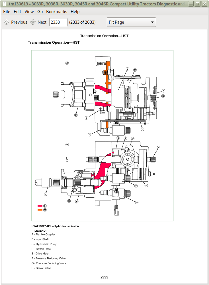
Transmission Operation—HST
Range Transmission Power Flow—HST
Control Valve Operation—PRT
Forward Clutch Operation—PRT
Reverse Clutch Operation—PRT
Transmission Operation—PRT
Differential Power Flow and Lock Theory of Operation
MFWD Power Theory of Operation
MFWD Power Flow Theory of Operation
PTO Clutch and Brake Theory of Operation
Rear PTO Theory of Operation
Mid PTO Theory of Operation
Group 30A: Schematics
Drivetrain Hydraulic Schematic — HST
Drivetrain Hydraulic Schematic — PRT
Group 40A: Drive Systems and Transmission Component and Connector Information
Drive Systems and Transmission Component and Connector Overview (HST)
Drive Systems and Transmission Component and Connector Overview (PRT)
C301 PR Clutch Pack
C601 PTO Clutch
G301 Hydrostatic Transmission
G302 PRT Control Valve
M301 Hydrostatic System Hydraulic Motor
P301 Hydrostatic System Hydraulic Pump
Group 50A: Tests and Adjustments
Hydrostatic High-Pressure Relief Test—HST
Charge Pump Pressure Test—PTH
Clutch Linkage Adjustment and Test—PRT
Forward Clutch Pressure Test—PRT
Reverse Clutch Pressure Test—PRT
Lube Pressure Test—PRT
Differential Pinion Shaft Adjustment
Differential Backlash Adjustment
Transmission Range Adjustment
PTO Selector Cable Adjustment
PTO Valve Pressure Test
PTO Valve Flow Test
Differential Lock Cable Adjustment
MFWD Cable Adjustment
MFWD Driveline Test
Section 260: Steering and Brakes Operation, Test, and Adjustments
Group 05: General References
Steering and Brakes Operation, Test, and Adjustments—Summary of References
Install Test Equipment 60-1
Install Test Equipment 60-2
Group 10A: Calibrations, Preliminary Checks and Operational Chedks—Steering
Steering - Preliminary Check
Steering - Operational Check
Group 10B: Calibrations, Preliminary Checks and Operational Checks—Brakes
Brakes - Preliminary Check
Brakes - Operational Check
Group 20A: Theory of Operation—Steering
Steering System Operation
Group 20B: Theory of Operation—Brakes
Brake System Theory of Operation
Group 30A: Schematics—Steering
Steering System Functional Schematic
Group 40A: Component and Connector Information—Steering
Steering System Component and Connector Overview
C101 Steering Cylinder
G101 Steering Control Valve
P001 Steering Pump
Group 40B: Component and Connector Information—Brakes
Brake System Component and Connector Overview (Cab)—HST
Brake System Component and Connector Overview (Open Station)—HST
Brake System Component and Connector Overview—PRT
Group 50A: Tests and Adjustments—Steering
Steering Pressure Check
Steering Pump Flow Test
Steering System Test
Toe-in Adjustment MFWD
Group 50B: Tests and Adjustments—Brakes
Brake Pedal Adjustment—PTH
Brake Pedal Adjustment—PTR
Brake Switch Adjustment
Parking Brake Adjustment
Section 270: Hydraulics Operation, Test, and Adjustments
Group 05: General References
Hydraulics—Summary of References
Install Test Equipment 70-1
Group 10: Calibrations, Preliminary Checks and Operational Checks
Hydraulics - Preliminary Check
Hydraulics - Operational Check
Group 20: Theory of Operation
Hydraulic Theory of Operation—HST
Hydraulic Theory of Operation—PRT
PTO Clutch Theory of Operation
PTO Valve Theory of Operation
Rockshaft Theory of Operation
Diverter Valve Theory of Operation
Group 30: Hydraulic Schematics
Hydraulic Functional Schematics—HST
Hydraulic Functional Schematics—PRT
Diverter Valve Schematics
Group 40: Component and Connector Information
Hydraulic System Component and Connector Overview
A601 PTO Clutch Accumulator
C401 Rockshaft Cylinder
F001 Suction Filter
F002 High Pressure Filter
F003 Mesh Filter
G401 Rockshaft Control Manifold
G402 Rockshaft Control Valve
G501 Dual Mid SCV Valve
H001 Hydraulic Oil Cooler
P002 Implement Pump
V507 Diverter Valve 1
V508 Diverter Valve 2
Group 50: Tests and Adjustments
Multi-Function Lever Cable Adjustment
Heating Hydraulic Oil
Hydraulic System Bleed Procedure
Hydraulic Pump Relief Valve Test
Hydraulic Pump Relief Valve Adjustment
Hydraulic Pump Flow Test
Rate of Drop/Stop Valve Adjustment
Lift Arms Adjustment
Rockshaft Cable Adjustment
Rockshaft Lift Cycle Test
Rockshaft Leakage Test
Rockshaft Position Feedback Linkage Adjustment
Section 290: Cab/Open Operators Station Operation, Test, and Adjustments
Group 05: General References
Cab/Open Operators Station Operation, Test, and Adjustments—Summary of References
System Information
Refrigerant Oil Information
Determine Correct Refrigerant Oil Charge
Install Test Equipment 90-1
Group 10: Calibrations, Preliminary Checks and Operational Checks
Operator Station - HVAC Preliminary Checks
Operator Station - HVAC Operational Checks
Group 20: Theory of Operation
Operator Station - Air Conditioning System Operation
Operator Station - Air Conditioning Compressor Operation
Operator Station - Air Conditioning Condenser Operation
Operator Station - Air Conditioning Evaporator Operation
Operator Station - Air Conditioning Expansion Valve Operation
Operator Station - Air Conditioning Receiver/Dryer Operation
Operator Station - Air Conditioning Temperature Control Switch Operation
Group 30: Schematics
Operator Station - Schematics
Group 40: Component and Connector Information
Operator Station - Component and Connector Information
Group 50: Tests and Adjustments
A/C Compressor Belt Adjustment
Heater Temperature Control Cable Adjustment
Air Conditioner Temperature Control Switch Cable Adjustment
Compressor Shaft Seal Leakage Test
Compressor Clutch Hub Clearance Check
Evaporator/Heater Core Leak Test
Compressor Oil Charge Check
Add Refrigerant Oil to System
Recover/Recycle Refrigerant
Evacuate Air Conditioning System
Charge Air Conditioning System
Flush Air Conditioning System
Expansion Valve Bench Test
Air Conditioning—System Static Pressure Test
Air Conditioning—System Pressure Test
Air Conditioning—Temperature Drop Test
Section 299: Service Tools
Group 05A: General References
Service Tools - Summary of References
Group 05C: Dealer Fabricated and Service Tools
DFRW20 Compressor Holding Fixture
John Deere Compact Utility Tractors Models 3033R, 3038R, 3039R, 3045R, 3046R Service Technical Manual (TM130619)
![]()