
John Deere Compact Utility Tractors Models 3028EN, 3036E, 3036EN Service Technical Manual (TM902119)
John Deere Compact Utility Tractors Models 3028EN, 3036E, 3036EN Service Technical Manual (TM902119)
TM902119 - John Deere Compact Utility Tractors Models 3028EN, 3036E, 3036EN Technical Manual (Diagnosis Operation Tests Repair Service).PDF
All Inclusive Technical Manual with Electrical Wiring Diagrams for John Deere 3028EN, 3036E, 3036EN Compact Utility Tractors (July 2015, 1PY, Asia), with all the shop information to maintain, diagnostic, repair, rebuild like professional mechanics.
John Deere Compact Utility Tractors Models 3028EN, 3036E, 3036EN workshop Diagnostic and Repair manual includes:
* Numbered table of contents easy to use so that you can find the information you need fast.
* Detailed sub-steps expand on repair procedure information
* Numbered instructions guide you through every repair procedure step by step.
* Troubleshooting and electrical service procedures are combined with detailed wiring diagrams for ease of use.
* Notes, cautions and warnings throughout each chapter pinpoint critical information.
* Bold figure number help you quickly match illustrations with instructions.
* Detailed illustrations, drawings and photos guide you through every procedure.
* Enlarged inset helps you identify and examine parts in detail.
Total Pages: 1,521 pages
File Format: PDF (bookmarked, ToC, Searchable, Printable, high quality)
Language: English
MAIN SECTIONS
Foreword
Safety
Safety
Specifications and Information
General Specifications
Fuel and Lubricants
Serial Number Locations
Engine
Specifications
Component Location
Theory of Operation
Diagnostics
Tests and Adjustments
Repair
Special Tools and Other Materials
Electrical System
General Information and Specification
Electrical System Component
Theory Of Operation
Diagnosis, Tests and Adjustments
Electrical Repair
Electrical Schematics
Electrical Components and Connectors
Power Train-SyncReverser™
General References
Specifications
Component Location
Theory of Operation
Diagnosis, Tests and Adjustments
Repair
Power Train-Final Drives
Specifications
Component Location
Theory of Operation
Diagnosis, Tests and Adjustments
Repair
Hydraulic System
Specification
Hydraulic System Components
Theory of Operation
Diagnosis, Tests and Adjustments
Hydraulic Schematics
Hydraulic Repair
Steering System
Specifications
Steering System Component
Theory of Operation
Diagnosis, Tests and Adjustments
Repair
Brake System
Specifications
Component Location
Theory of Operation
Diagnosis, Tests and Adjustments
Repair
Miscellaneous
Specifications
Front Axle Repair
Wheels Repair
Cowl
3-Point Hitch
Operational Checkout Procedures
Operational Checkout Procedures
Operator Station
Seat and Support
Operator Platform
Fenders
Hood
Roll-Gard™
Special Tools
Dealer Fabricated Tools
tm902119 - 3036E, 3028EN and 3036EN Tractor (Worldwide Edition)
Table of Contents
Foreword
Section 10: Safety
Group 05: Safety
Recognize Safety Information
Understand Signal Words
Follow Safety Instructions
Prepare for Emergencies
Wear Protective Clothing
Protect Against Noise
Handle Fuel Safely—Avoid Fires
Handle Starting Fluid Safely
Fire Prevention
In Case of Fire
Avoid Static Electricity Risk When Refueling
Keep ROPS Installed Properly
Use Foldable ROPS and Seat Belt Properly
Stay Clear of Rotating Drivelines
Use Steps and Handholds Correctly
Read Operator’s Manuals for ISOBUS Controllers
Use Seat Belt Properly
Operating the Tractor Safely
Avoid Backover Accidents
Limited Use in Forestry Operation
Operating the Loader Tractor Safely
Keep Riders Off Machine
Instructional Seat
Use Safety Lights and Devices
Transport Towed Equipment at Safe Speeds
Use Caution on Slopes, Uneven Terrain, and Rough Ground
Freeing a Mired Machine
Avoid Contact with Agricultural Chemicals
Handle Agricultural Chemicals Safely
Handling Batteries Safely
Avoid Heating Near Pressurized Fluid Lines
Remove Paint Before Welding or Heating
Handle Electronic Components and Brackets Safely
Practice Safe Maintenance
Avoid Hot Exhaust
Clean Exhaust Filter Safely
Work In Ventilated Area
Support Machine Properly
Prevent Machine Runaway
Park Machine Safely
Transport Tractor Safely
Service Cooling System Safely
Service Accumulator Systems Safely
Service Tires Safely
Service Front-Wheel Drive Tractor Safely
Tightening Wheel Retaining Bolts/Nuts
Avoid High-Pressure Fluids
Do Not Open High-Pressure Fuel System
Store Attachments Safely
Decommissioning — Proper Recycling and Disposal of Fluids and Components
Section 20: Specifications and Information
Group 05: General Specifications
John Deere 3028EN Tractor
John Deere 3036E Tractor
John Deere 3036EN Tractor
Ground Speed at Rated Engine Speed (2800 rpm)
Metric Bolt and Screw Torque Values
Metric Cap Screw Torque Values—Grade 7
Unified Inch Bolt and Screw Torque Values
Gasket Sealant Application
Service Recommendations For Flat Face O-Ring Seal Fittings
Service Recommendations for O-Ring Boss Fittings
Group 10: Fuel and Lubricants
Diesel Fuel
Handling and Storing Diesel Fuel
Diesel Engine Oil — Non-Emissions Certified and Certified Tier 1 and Stage I
Diesel Engine Break-In Oil — Non-Emissions Certified and Certified Tier 1, Tier 2, Tier 3, Stage I, Stage II, and Stage III
Alternative and Synthetic Lubricants
Lubricant Storage
Mixing of Lubricants
Multipurpose Extreme Pressure (EP) Grease
Transmission and Hydraulic Oil
Tractor Engine Coolant
Group 15: Serial Number Locations
Serial Numbers
Machine Product Identification Number
Front Axle Serial Number
Engine Serial Number
Transmission Serial Number
ROPS Certificate and Serial Number
Keep Machines Secure
Section 30: Engine
Group 05: Specifications
General Specifications
Repair Specifications
Tests and Adjustment Specifications
Operational Tests
Torque Values, Non-Standard Fasteners
Group 10: Component Location
Air Cleaner and Intake Components (For 3036E)
Air Cleaner and Intake Components (For 3028EN and 3036EN)
Fuel Supply Components (For 3036E)
Fuel Supply Components (For 3028EN and 3036EN)
Engine Throttle Components (For 3036E)
Engine Throttle Components (For 3028EN and 3036EN)
Group 15: Theory of Operation
General Engine Operation
Head Gasket Joint Construction and Operation
Fuel System Operation
Cooling System Component Location Diagram
Cooling System Operation
Air Intake System
Lubrication System Operation
Group 20: Diagnostics
Engine Troubleshooting
Engine Oil Diagnostics
Excessive Fuel Consumption
Incorrect Manifold Pressure
Low Engine Compression
Engine Starting Problem
Engine Operation Poor
Engine Oil Pressure Low
Coolant Temperature Abnormal
Coolant in Oil or Oil in Coolant
Diagnostic Table
Check for Head Gasket Failures
Group 25: Tests and Adjustments
Check Air Intake System (For 3036E)
Check Air Intake System (For 3028EN and 3036EN)
Air Restriction Indicator Test
Check for Intake and Exhaust Restrictions
Fan/Alternator Drive Belt Adjustment
Throttle Rod Adjustment (For 3036E)
Throttle Rod Adjustment (For 3028EN and 3036EN)
Slow Idle Adjustment
Cylinder Compression Test
Valve Clearance Adjustment
Valve Lift Check
Radiator Bubble Test
Thermostat Opening Test
Radiator Pressure Cap Test
Cooling System Pressure Test
Engine Oil Pressure Test
Fuel System Leakage Test
Bleed Fuel System
Fuel Supply Pump Pressure Test
Injection Pump Timing
Fuel Injection Nozzle Test
Crankshaft End Play Check
Timing Gear Backlash Check
Camshaft End Play Check
Connecting Rod Side Play Check
Connecting Rod Bearing Clearance Check
Crankshaft Main Bearing Clearance Check
Group 30: Repair
Radiator Removal and Installation (For 3036E)
Radiator Removal and Installation (For 3028EN and 3036EN)
Thermostat Removal and Installation (For 3036E)
Thermostat Removal and Installation (For 3028EN and 3036EN)
Water Pump Removal and Installation (For 3036E)
Water Pump Removal and Installation (For 3028EN and 3036EN)
Alternator Fan Belt Removal and Installation (For 3036E)
Alternator Fan Belt Removal and Installation (For 3028EN and 3036EN)
Fuel Tank Removal and Installation (For 3036E)
Fuel Tank Removal and Installation (For 3028EN and 3036EN)
Water Separator (For 3036E)
Water Separator (For 3028EN and 3036EN)
Secondary Fuel Filter
Remove, and Install Air Cleaner Assembly
Fuel Injection Pump (For 3036E)
Fuel Injection Pump (For 3028EN and 3036EN)
Fuel Injection Nozzles
Intake Manifold
Muffler Removal and Installation (For 3036E)
Muffler Removal and Installation (For 3028EN and 3036EN)
Exhaust Manifold
Starting Motor Removal and Installation (For 3036E)
Starting Motor Removal and Installation (For 3028EN and 3036EN)
Alternator Removal and Installation (For 3036E)
Alternator Removal and Installation (For 3028EN and 3036EN)
Rocker Cover Removal and Installation
Engine Removal and Installation (For 3036E)
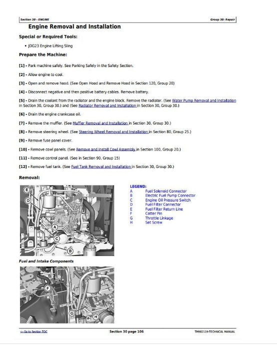
Engine Removal and Installation (For 3028EN and 3036EN)
Engine Repair Stand
Install Engine Adapter on Repair Stand
Install Lift Straps
Lifting Procedure
Rocker Arm Assembly
Cylinder Head and Valves Removal and Installation
Cylinder Head and Valves Disassembly and Assembly
Cylinder Head Gasket — Inspection
Valve Seats
Intake / Exhaust Valves Removal and Installation
Valve Recession
Valve Guides
Valve Guides Inspection, Removal and Installation
Valve Springs
Grind Valve Seats
Lap Valves
Measure Piston-To-Cylinder Head Clearance
Piston and Connecting Rod
Piston Inspection
Cylinder Bore
Crankshaft Front Oil Seal Removal
Crankshaft Rear Oil Seal Replacement
Crankshaft and Main Bearings
Flywheel and Coupling
Camshaft Removal and Installation
Camshaft Followers
Gear Case Cover Removal and Installation
Timing Gear Cover
Idler Gear Inspection, Removal and Installation
Timing Gear Cover Mounting Plate
Oil Pan and Crankcase Housing Extension
Oil Pump
Group 35: Special Tools and Other Materials
Special Tools
Other Materials
Section 40: Electrical System
Group 05: General Information and Specification
Reading Electrical Schematics
Theory of Operation Information
Diagnostic Information
Wire Color Abbreviation Chart
Common Circuit Tests
Conductors for 12-Volt Circuits
System Specifications
Essential or Recommended Tools
Other Materials
Service Equipment and Tools
Other Material
Group 10: Electrical System Component
Electrical Components
Control Panel
Fuses and Fuse Box (Load Center)
Group 15: Theory Of Operation
Theory of Operation Information
Fuses and Fuse Box (Load Center)
Relays
Starting System Operation
Charging System Operation
Turn Signal and Warning Light Operation
Head Lamp and Parking Lamp (Tail / Stop Lamp) Operation
Fuel Gauge Operation
Temperature Gauge Operation
Air Filter Restriction Indicator Operation
7-Pin Trailer Outlet Connector Operation
Horn Operation
Flood Light Operation
Brake Switch Operation
Engine Oil Pressure Indicator Operation
Group 20: Diagnosis, Tests and Adjustments
How to Use Electrical Tests and Adjustments Information
Troubleshooting Unresolved Electrical/Electronic Problems
Connector Test
Diode Test
Fuse Test
Light Test
Miscellaneous Component Test
Motor Test
Pump Test
Relay Test
Resistor Test
Sensor Test
Solenoid Test
Switch Test
Battery Voltage and Specific Gravity Tests
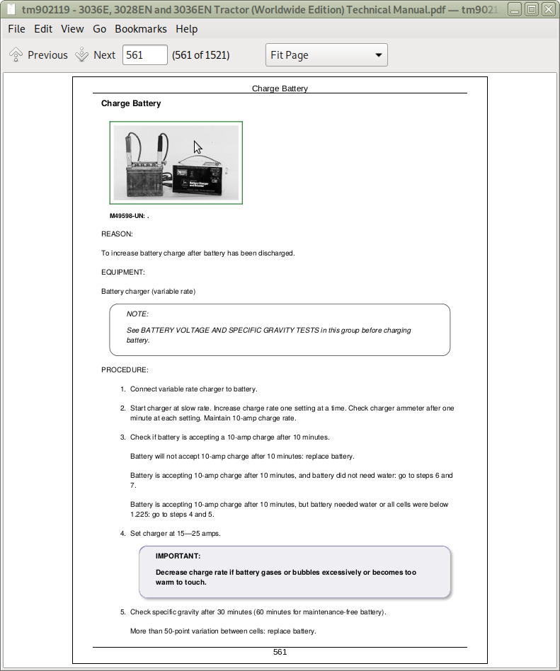
Charge Battery
Battery Load Test
Starter AMP Draw/RPM Test
Starter No-Load AMP Draw/RPM Test
Alternator/Regulator Test
Starter Solenoid Test
Starter Relay Test
Key Switch Test
Plug-In Relay Test
Diode Pack Test
Fuse Test
Neutral Start Switch Test
PTO Switch Test
Light Switch Test
Turn/Hazard Switch Test
Fuel Shut-Off Solenoid Test
Group 25: Electrical Repair
Remove and Install Battery (For 3036E)
Remove and Install Battery (For 3028EN and 3036EN)
Starting Motor Removal and Installation
Starter Motor — Assemble
Starter Motor — Installation
Starter Motor — No-Load Test
Starter Motor — Removal
Starter Motor — Tear Down
Starter Motor Armature — Cleaning and Inspection
Starter Motor Field Coil — Cleaning and Inspection
Starter Motor Magnetic Switch — Cleaning and Inspection
Starter Motor Pinion Clutch Assembly — Cleaning and Inspection
Alternator Removal and Installation, 3036E
Alternator Removal and Installation, For 3028EN and 3036EN
Replace Air Filter Restriction Sensor
Replace Coolant Temperature Sender
Replace Engine Oil Pressure Sensor
Replace Key Switch
Replace Light Switch
Replace Turn Signal Controller and Hazard Switch
Replace Horn Switch
Replace Instrument Panel
Disassemble, Inspect and Assemble Instrument Cluster
Replace Neutral Start Switch
Replace Brake Switch
Replace Fuel Level Sender,3036E
Replace Fuel Level Sender, For 3028EN and 3036EN
Replace PTO Switch, 3036E
Replace PTO Switch, For 3028EN and 3036EN
Group 30: Electrical Schematics
Schematic Information
Component Identification Table
Quick Reference Table
Reference Tables
Alternator, Starter Motor, and Key Switch (SE01) (For 3036E)
Light Circuit (SE02) (For 3036E)
Instrument Cluster and Trailer Connector (SE03) (For 3036E)
Alternator, Starter Motor, and Key Switch (SE01) (For 3028EN and 3036EN)
Light Circuit (SE02) (For 3028EN and 3036EN)
Instrument Cluster (SE03) (For 3028EN and 3036EN)
Trailer Connector (SE04) (For 3028EN and 3036EN)
Trailer Connector (SE04) (For 3028EN and 3036EN) (SAE)
Trailer Connector (SE04) (For 3028EN and 3036EN) (ISO)
Group 40: Electrical Components and Connectors
A01—Instrument Cluster
B01—Air Filter Switch
B02—Fuel Level Sendor
B03—Coolant Temperature Switch
B04—Engine Oil Pressure Switch
E01—Right Head Lamp
E02—Left Head Lamp
E05—Right Turn / Hazard Light (3036E)
E06—Left Turn / Hazard Light (3036E)
E07—Rear Right Tail / Stop Lamp (3036E)
E08—Rear Left Tail / stop Lamp (3036E)
E11—Work Lamp
G01—Battery
G02—Alternator
H01—Vehicle Horn
K01—PTO Off Neutral Relay
K02—Starter Relay
K03—Latch Relay
K04—Solenoid Relay
K05—Fuel Flow Relay
K06—Flasher
M01—Starter Motor
M02—Fuel Pump
S01—Key Switch
S02—Neutral Start Switch
S03—Rear PTO Switch
S04—Light Switch
S06—Turn / Hazard Switch
S07—Horn Switch
S08—Brake Switch
T01—Delay Timer
V01—Diode Block
X01—7 Pin Connector for Trailer Connection
X02—12 Pin Connector for Interconnect to Rear Wiring Harness
X03—6 Pin Connector for Hood Harness Interconnect
X04—12 Pin Inter Connect Front Harness
Y01—Fuel Shut Off Solenoid
E12—Right-Hand Side Rear Combination Lamp (3028EN and 3036EN)
E13—Left-Hand Side Rear Combination Lamp (3028EN and 3036EN)
E14—License Plate Lamp (3028EN and 3036EN)
Section 50: Power Train—SyncReverser™
Group 05A: General References
Power Train—SyncReverser™ - Summary of References
Group 05: Specifications
General Specifications
Repair Specifications
Torque Specifications
Essential or Recommended Tools
Other Material
Group 10: Component Location
Transmission Components
Transmission Case — Clutch Housing
Drive Shaft Assembly, Speed (Driving)
Drive Shaft Assembly, Speed (Driven)
Drive Shaft Assembly, Range (Driven)
Drive Shaft Assembly, MFWD (Driven)
Shifter Assembly, Speed
Shifter Assembly, Range and MFWD
Countershaft Assembly with Synchronizer, Forward-Reverse
Input Shaft Assembly, Forward-Reverse
Shifter Assembly, Forward-Reverse
Reverse Idler Shaft
Group 15: Theory of Operation
SyncReverser™ Transmission (For 3036E)
SyncReverser™ Transmission (For 3028EN and 3036EN)
Single Clutch Operation
Transmission Power Flow—Forward Drive (A Range)
Transmission Power Flow—Forward Drive (B Range)
Transmission Power Flow—Reverse Drive (A Range)
Transmission Power Flow—Reverse Drive (B Range)
Group 20: Diagnosis, Tests and Adjustments
Diagnostic Information
Isolate the Problem Area
Traction Clutch Slips
Traction Clutch Dragging
Traction Clutch Does Not Engage
Traction Clutch Grabs
Traction Clutch Squeaks
Traction Clutch Does Not Release
Traction Clutch Chatters
Traction Clutch Rattles
Traction Clutch Engagement Is Noisy
Excessive Vibration in Traction Clutch
Clutch Pedal Does Not Return
Clutch Pedal Loose
Clutch Pedal Pulsates
Jerky or Rough Transmission of Power
Low Transmission Oil Level (Excessive Oil Leakage or Seepage)
Gears Clash, Shifts Hard, or Will Not Engage
Transmission Will Not Stay in Gear
Transmission Noisy
Clutch Pedal Free Play Adjustment (3036E)
Clutch Pedal Free Play Adjustment (For 3028EN and 3036EN)
Group 25: Repair
Remove And Install Transmission (For 3036E)
Remove and Install Transmission (For 3028EN and 3036EN)
Remove and Install Clutch Assembly
Remove and Inspect Clutch Release Mechanism and Shaft
Install Clutch Release Mechanism and Shaft
Remove, Inspect, and Repair Gear Shift Lever Assembly (For 3036E)
Remove, Inspect, and Repair Gear Shift Lever Assembly (For 3028EN and 3036EN)
Remove, Inspect and Repair Range Shift Lever Assembly (For 3036E)
Remove Inspect, and Repair Range Shift Lever Assembly (For 3028EN and 3036EN)
Forward-Reverse Retainer Oil Seal Replacement
Disassemble, Inspect, and Assemble Shift Shaft Assemblies (Speed)
Disassemble, Inspect and Assemble Shift Shaft Assemblies (Range and MFWD)
Disassemble, Inspect, and Assemble Shift Shaft Assemblies (Forward-Reverse)
Disassemble, Inspect, and Assemble Input Shaft and Reverse Idler (Forward-Reverse)
Disassemble and Inspect Countershaft—Forward-Reverse
Disassemble, Inspect and Assemble Drive Shaft Assembly, Speed (Driving)
Disassemble, Inspect and Assemble Drive Shaft Assembly, Speed (Driven)
Disassemble, Inspect, and Assemble Drive Shaft Assembly, Range (Driven)
Disassemble, Inspect and Assemble Drive Shaft Assembly, MFWD (Driven)
Section 60: Power Train—Final Drives
Group 05: Specifications
Specifications—Differential
Specifications—Final Drives
Specifications—Rear PTO
Essential or Recommended Tools—Differential
Essential or Recommended Tools—Final Drives
Essential or Recommended Tools—Rear PTO
Essential or Recommended Tools
Other Material
Group 10: Component Location
Final Drive Components
Rear PTO Components (For 3036E)
Rear PTO Components (For 3028EN and 3036EN)
Rear PTO Shift Assembly
Group 15: Theory of Operation
Final Drive Operation
Rear PTO Operation (Dual Speed for 3036E)
Rear PTO Operation (Dual Speed for 3028EN and 3036EN)
Differential Power Flow
Differential Power Flow and Lock
Group 20: Diagnosis, Tests and Adjustments
Differential Cone Point Adjustment- For 2 Pinion Differential
Differential Backlash Adjustment
PTO Noisy
PTO Hard to Engage
PTO Will Not Operate
PTO Will Not Stay Engaged
Excessive Differential Noise
Differential Does Not Work
Differential Chatters
Axle Noise
Axle Shaft Will Not Turn
Differential Lock Symptom Diagnosis
Group 25: Repair
Remove and Install Differential Assembly
Disassemble, Inspect, and Assemble 2 Pinion Differential Assembly
Remove and Inspect Differential Drive Shaft
Install Differential Drive Shaft
Remove, Inspect and Install Differential Lock Assembly
Disassemble and Inspect Rear Drive Assembly
Remove and Install Final Drive Assembly (For 3036E)
Remove and Install Final Drive Assembly (For 3028EN and 3036EN)
Install Rear Drive Assembly
Remove and Inspect Rear Axle Shaft Assembly (For 3036E)
Remove and Inspect Rear Axle Shaft Assembly (For 3028EN and 3036EN)
Install Rear Axle Shaft Assembly (For 3036E)
Install Rear Axle Shaft Assembly (For 3028EN and 3036EN)
Remove and Install Rear PTO Assembly
Disassemble, Inspect, and Assemble Rear PTO Cover and Retainer
Disassemble and Inspect Rear PTO Output shaft
Assemble Rear PTO Output shaft
Section 70: Hydraulic System
Group 05: Specification
Special Tools
Service Parts Kits
Other Material
Hydraulic Specifications
Repair Specifications
Group 10: Hydraulic System Components
Hydraulic System Components—Summary of References
Hydraulic System Component Information
Hydraulic System Components
Group 15: Theory of Operation
Theory of Operation—Summary of References
Theory of Operation Information
Hydraulic System Operation
Hydraulic Filter Operation, 3036E
Hydraulic Filter Operation, 3028EN and 3036EN
Hydraulic Pump Operation
Rockshaft Operation
Group 20: Diagnosis, Tests and Adjustments
Diagnostic Information
Preliminary Hydraulic System Inspection
Entire Hydraulic System Fails to Function/No Hydraulic Pump Output
Insufficient Pump Delivery
Hydraulic Functions Too Slow
Excessive Pump Pressure
Slow Hydraulic Pump Response
Excessive Pump Noise During Operation
Rockshaft Jerking in Lift Position
Rockshaft Does Not Lift or Lifts Slowly
Rockshaft Does Not Lower or Lowers Slowly
Rockshaft Lowering Automatically
Position Control Lever too Hard or Loose
External Hydraulic Connection Not Working
Insufficient Maximum Lift of Implement
Rockshaft Over Heating
Lift Capacity Does Not Correspond as Recommended
Rockshaft too Responsive
Hydraulic System Tests
System Pressure and Flow Test
Rockshaft Lift Cycle Test
Rockshaft Leakage Test
Main Relief Valve Test
Hydraulic System Bleed Procedure
Rate of Drop and Stop Valve Adjustment
Lift Arms Adjustment
System Pressure Adjustment
Rockshaft Position Feedback Linkage Adjustment
Group 25: Hydraulic Schematics
Hydraulic Circuit Symbols
Hydraulic Schematics
Group 30: Hydraulic Repair
Remove and Install Hydraulic Pump
Inspect and Replace Hydraulic Suction Lines, 3036E
Inspect and Replace Hydraulic Suction Lines, 3028EN and 3036EN
Inspect and Replace Hitch Pump outlet Lines, 3036E
Inspect and Replace Hitch Pump outlet Lines, 3028EN and 3036EN
Remove and Install Hydraulic Oil Filter / Canister, 3036E
Remove and Install Hydraulic Oil Filter / Canister, 3028EN and 3036EN
Change Transmission-Hydraulic Oil Filter Element
Rockshaft Removal and Installation
Rockshaft Cylinder Disassembly and Assembly
Rockshaft Control Valve Removal and Installation
Rockshaft Control Valve Disassembly and Assembly
Rockshaft Lift Arms Removal and Installation, (For 3036E)
Rockshaft Lift Arms Removal and Installation (For 3028EN and 3036EN)
Section 80: Steering System
Group 05: Specifications
Steering Specifications
Torque Specifications
Service Equipment and Tools
Group 10: Steering System Component
Steering System Components (For 3036E)
Steering System Components (For 3028EN and 3036EN)
Group 15: Theory of Operation
Theory of Operation Information
Steering System Operation (For 3036E)
Steering System Operation (For 3028EN and 3036EN)
Steering Valve Operation—Neutral
Steering Valve Operation—Power Turning
Group 20: Diagnosis, Tests and Adjustments
Diagnosis, Tests and Adjustments—Summary of References
Diagnostic Information
Isolate the Problem—Steering System
Steering Sluggish or Loss of Steering
Steering Pressure Check
Steering System Test
Steering Pump Flow Test
Steering Valve Relief Test
Steering Cylinder Leakage Test
Steering Valve Leakage Test
Check Toe-In (MFWD Tractor)
Adjust Toe-In (MFWD Tractor)
Group 25: Repair
Remove and Install Steering Pump (For 3036E)
Remove and Install Steering Pump (For 3028EN and 3036EN)
Steering Cylinder Removal and Installation MFWD
Steering Wheel Removal and Installation
Steering Control Unit (SCU) Removal and Installation
Tie Rod Removal and Installation MFWD
Section 90: Brake System
Group 05: Specifications
Brakes Specifications (For 3036E)
Brakes Specifications (For 3028EN and 3036EN)
Essential or Recommended Tools
Group 10: Component Location
Brake System Components
Brake Assembly Components
Group 15: Theory of Operation
Brake System Operation
Group 20: Diagnosis, Tests and Adjustments
Adjust Brake Pedal Free Play
Diagnostic Information
Isolate the Problem—Brakes
Brake Pedals and Linkage Checks
Brake Operation Problems
Internal Components
Group 25: Repair
Remove and Inspect Brakes
Install Brakes
Section 100: Miscellaneous
Group 05: Specifications
Torque Specifications
Group 10: Front Axle Repair
Identification View
Maintenance Points
Maintenance Intervals
MFWD Drive Shaft & Hydraulic Line Removal (For 3036E)
MFWD Drive Shaft & Hydraulic Line Removal (For 3036EN and 3028EN)
Axle Removal (For 3036E Light Duty Front Axle)
Axle Removal (For 3036EN and 3028EN)
Steering Cylinder Removal
Tie Rod Removal
Drain Plug Removal
Final Drive Cover Disassembly
Final Drive Cover Installation
Drop Shaft and Knuckle Disassembly
Drop Shaft & Knuckle Assembly
Shoulder Disassembly
Shoulder Assembly
Cassette Seal Installation
Face Seal Installation
Center Section Removal & Disassembly
Center Section Assembly & Installation
Drain Plug Installation
Tie Rod Installation
Steering Cylinder Installation
Axle Trunnion Installation
Assemble Front Trunnion
Axle Installation & Toe-In Adjustment
Drive shaft & Hydraulic Line Installation
Essential or Recommended Tools—Front Axle
Group 11: Front Axle Repair (Heavy Duty 3036E)
Identification View
Maintenance Points
Maintenance Intervals
Drain Plug Removal
MFWD Drive Shaft and Hydraulic Line Removal
Front Axle Removal
Steering Cylinder Removal
Tie Rod Removal
Final Drive Cover Disassembly
Final Drive Cover Installation
Drop Shaft Disassembly
Drop Shaft Assembly and Installation
Knuckle Housing Removal
Knuckle Housing Installation
Shoulder Housing Removal and Disassembly
Shoulder Housing Assembly
Cassette Seal Installation
Face Seal Installation
Center Section Removal and Disassembly
Center Section Assembly and Installation
Drain Plug Installation
Tie Rod Installation
Steering Cylinder Installation
Axle Trunnion Installation
Axle Installation and End Play Adjustment
Toe-In Adjustment
Drive shaft and Hydraulic Line Installation
Group 15: Wheels Repair
Remove and Install Front or Rear Wheels
Tire Inflation Pressure Chart (For 3036EN and 3028EN)
Front and Rear Tire Combinations—MFWD (For 3036EN and 3028EN)
Tread Settings—Multi-Position Rear Wheels (For 3036EN and 3028EN)
Tread Settings—MFWD Front Axle (For 3036EN and 3028EN)
Tread Setting—Front and Rear Wheels (For 3036EN and 3028EN)
Tire Inflation Pressure Chart (For 3036EN Export)
Front and Rear Tire Combinations—MFWD (For 3036EN Export)
Tread Settings—Multi-Position Rear Wheels (For 3036EN Export)
Tread Settings—MFWD Front Axle (For 3036EN Export)
Tread Setting—Front and Rear Wheels (For 3036EN Export)
Group 20: Cowl
Remove and Install Cowl Assembly (For 3036E)
Remove and Install Cowl Assembly (For 3036EN and 3028EN)
Group 30: 3-Point Hitch
Specifications (For 3036E)
Specifications (For 3036EN and 3028EN)
Inspect and Repair Fixed Draft Links
Inspect and Repair Adjustable Lift Link (For 3036E)
Inspect and Repair Adjustable Lift Link (For 3036EN and 3028EN)
Inspect and Repair Fixed Lift Link
Inspect and Repair Center Link
Remove and Install Drawbar Hitch (For 3036E)
Remove and Install Drawbar Hitch (For 3036EN and 3028EN)
Section 110: Operational Checkout Procedures
Group 05: Operational Checkout Procedures
Operational Checkout Procedure Information
Engine Oil Level and Condition Check
Coolant Level and Condition Check
Transmission and Hydraulic Oil Check (For 3036E)
Transmission and Hydraulic Oil Check (For 3028EN and 3036EN)
Fan and Belt Check
Fuel System Check
Air Intake System Check (For 3036E)
Air Intake System Check (For 3028EN and 3036EN)
Electrical System Check (For 3036E)
Electrical System Check (For 3028EN and 3036EN)
Hydraulic System Check
Indicator Lamps Check
Engine Start Check
Transmission Neutral Start Check (For 3036E)
Transmission Neutral Start Check (For 3028EN and 3036EN)
Engine Fast and Slow Idle Operation
Power Steering Check
Clutch Check
Speed Lever Shift Check (For 3036E)
Speed Lever Shift Check (For 3028EN and 3036EN)
Range Lever Shift Check (For 3036E)
Range Lever Shift Check (For 3028EN and 3036EN)
Brake Check
Rockshaft Check (For 3036E)
Rockshaft Check (For 3028EN and 3036EN)
Miscellaneous Checks
Section 120: Operator Station
Group 05: Seat and Support
Specifications (For 3036E )
Specifications (For 3036EN and 3028EN)
Remove and Install Seat and Support (For 3036E)
Remove and Install Seat and Support (For 3036EN and 3028EN)
Remove and Install Seat Closeout
Group 10: Operator Platform
Specifications
Remove and Install Floor Mat (3036E)
Remove and Install Floor Mat (3036EN and 3028EN)
Remove and Install Right-Side Platform (3036E)
Remove and Install Right-Side Platform (3036EN and 3028EN)
Remove and Install Left-Hand Side Platform and Step
Remove and Install Left-Hand Side Platform and Step (3036EN and 3028EN)
Group 15: Fenders
Specification
Remove and Install Fenders
Remove and Install Fenders (3036EN and 3028EN)
Group 20: Hood
Open Hood
Remove Hood (For 3036E)
Remove Hood (For 3036EN and 3028EN)
Group 25: Roll-Gard™
Specifications
Remove and Install Roll-Gard™ (For 3036E)
Remove and Install Roll-Gard™ (For 3036EN and 3028EN)
Section 130: Special Tools
Group 05: Dealer Fabricated Tools
Starter Wrench
![]()