
John Deere 2320 Compact Utility Tractor Service Technical Manual (TM2388)
All Inclusive Technical Manual with electrical wiring diagrams for John Deere 2320 Compact Utility Tractor, with all the technical information to maintain, diagnose, repair, and rebuild like professional mechanics.
John Deere Compact Utility Tractors 2320 workshop diagnostic operation test adjustments repair service manual includes:
* Numbered table of contents easy to use so that you can find the information you need fast.
* Detailed sub-steps expand on repair procedure information
* Numbered instructions guide you through every repair procedure step by step.
* Troubleshooting and electrical service procedures are combined with detailed wiring diagrams for ease of use.
* Notes, cautions and warnings throughout each chapter pinpoint critical information.
* Bold figure number help you quickly match illustrations with instructions.
* Detailed illustrations, drawings and photos guide you through every procedure.
* Enlarged inset helps you identify and examine parts in detail.
tm2388 - Compact Utility Tractor 2320 Series Technical Manual.pdf
tm2388 - Compact Utility Tractor 2320 Series Technical Manual.epub
Total Pages: 1,147 pages
File Format: PDF/EPUB/MOBI/AZW (PC/Mac/Android/Kindle/iPhone/iPad; bookmarked, ToC, Searchable, Printable)
Language: English
MAIN SECTIONS
Foreword
Safety
Safety
Specifications and Information
General Specifications
Fuel and Lubricants
Serial Number Locations
Engine - Diesel
Specifications
Theory of Operation
Component Location
Diagnostics
Tests and Adjustments
Repair
Starting Motor
Electrical
General Information
Specifications
Component Location
System Schematics
Diagnostics & Operation
Tests and Adjustments
Export Electrical
Specifications
Component Location
System Schematics
Diagnostics and Operation
Power Train - Hydrostatic
Specifications
Component Location
Theory of Operation
Diagnostics
Tests and Adjustments
Repair
Hydraulics
Specifications
Component Locations
Hydraulic Schematics
Operation and Diagnostics
Troubleshooting
Theory of Operation
Tests and Adjustments
Repair
Steering
Specifications
Component Location
Theory of Operation
Diagnostics
Tests and Adjustments
Repair
Brakes
Specifications
Component Location
Theory of Operation
Diagnostics
Tests and Adjustments
Repair
Miscellaneous
Specifications
Repair
tm2388 - Compact Utility Tractor 2320 Series
Table of Contents
Foreword
Section 10: Safety
Group 05: Safety
Recognize Safety Information
Understand Signal Words
Replace Safety Signs
Handle Fluids Safely—Avoid Fires
Prepare for Emergencies
Prevent Battery Explosions
Prevent Acid Burns
Wear Protective Clothing
Avoid High-Pressure Fluids
Avoid Heating Near Pressurized Fluid Lines
Service Machines Safely
Use Proper Tools
Park Machine Safely
Support Machine Properly
Use Proper Lifting Equipment
Work in Clean Area
Protect Against High Pressure Spray
Illuminate Work Area Safely
Work In Ventilated Area
Remove Paint Before Welding or Heating
Avoid Harmful Asbestos Dust
Service Tires Safely
Stay Clear of Rotating Drivelines
Service Cooling System Safely
Dispose of Waste Properly
Handle Chemical Products Safely
Live With Safety
Section 20: Specifications and Information
Group 05: General Specifications
Metric Bolt and Screw Torque Values
Unified Inch Bolt and Screw Torque Values
Metric Cap Screw Torque Values—Grade 7
Gasket Sealant Application
Service Recommendations For Flat Face O-Ring Seal Fittings
Service Recommendations for O-Ring Boss Fittings
Group 10: Fuel and Lubricants
Diesel Fuel
Handling and Storing Diesel Fuel
Diesel Engine Oil
Diesel Engine Break-In Oil
Alternative and Synthetic Lubricants
Lubricant Storage
Mixing of Lubricants
Grease
Transmission and Hydraulic Oil
Heavy Duty Diesel Engine Coolant
Group 15: Serial Number Locations
Serial Numbers
Machine Product Identification Number
Engine Serial Number
Section 30: Engine - Diesel
Group 05: Specifications
General Specifications
Operational Tests
Tests and Adjustment Specifications
Repair Specifications
Torque Specifications
Service Equipment and Tools
Special Tools
Other Materials
Group 10: Theory of Operation
Cooling System Operation
Lubrication System Operation
Fuel System Theory of Operation
Air System Theory of Operation
Group 15: Component Location
Engine
Fuel System
Group 20: Diagnostics
Starting Problems
Low Engine Output
Exhaust Abnormal Under Load
Engine Runs Rough
Excessive Fuel Consumption
Lubricating Oil
Temperature Problems
Low Compression
Engine Diagnostic Table
Group 25: Tests and Adjustments
Cylinder Compression Test
Throttle Cable Adjustment
Slow Idle Adjustment
Valve Clearance Adjustment
Valve Lift Check
Fuel Injection System Tests
Fuel Injection Nozzle Test
Injection Pump Static Timing Check
Injection Pump Timing (EPA Engines)
Thermostat Test
Fan/Alternator Belt Adjustment
Radiator Bubble Test
Cooling System Pressure Test
Radiator Cap Pressure Test
Engine Oil Pressure Test
Fuel Transfer Pump Pressure Test
Fuel Pump Flow Test
Fuel System Leakage Test
Bleed Fuel System
Group 30: Repair
Fan/Alternator Belt Removal and Installation
Muffler Removal and Installation
Exhaust Manifold Removal and Installation
Rocker Arm Cover Removal and Installation
Radiator Removal and Installation
Engine Removal and Installation
Rocker Arm and Push Rods
Cylinder Head Removal and Installation
Cylinder Head Recondition
Crankshaft Oil Seals
Timing Gear Cover
Camshaft End Play Check
Timing Gear Backlash Check
Idler Gear
Camshaft Followers
Camshaft
Oil Pan and Strainer
Connecting Rod Side Play Check
Crankshaft End Play Check
Connecting Rod Bearing Clearance Check
Crankshaft Main Bearing Clearance Check
Piston-To-Cylinder Head Clearance
Piston and Connecting Rod Repair
Cylinder Bore
Crankshaft and Main Bearings
Flywheel Removal and Installation
Engine Back Plate
Timing Gear Housing
Oil Pump
Coolant Temperature Switch
Thermostat Removal and Installation
Water Pump
Fuel Transfer Pump
Fuel Injection Nozzle
Fuel Injection Pump
Fuel Shutoff Solenoid Removal and Installation
Fuel Control and Governor Linkage Removal and Installation
Fuel Filter Assembly Removal and Installation
Fuel Filter Removal and Installation
Group 35: Starting Motor
Starting Motor Removal and Installation
Starting Motor Disassembly and Assembly
Starting Motor Inspection and Test
Starting Motor Gear Train
Starting Motor Solenoid
20 Amp Alternator
High Capacity Alternator
Section 40: Electrical
Group 05: General Information
Reading Electrical Schematics
Theory Of Operation Information
Diagnostic Information
Wire Color Abbreviation Chart
Common Circuit Tests
Conductors for 12 Volt Circuits
Group 10: Specifications
System Specifications
Service Equipment and Tools
Other Materials
Group 15: Component Location
Electrical Components
Group 20: System Schematics
Schematic and Wiring Harness Legend
Electrical Schematic (1 of 4)
W1 Main Wiring Harness (1 of 4)
W2 Power Supply Wiring Harness
W3 Battery Cable Wiring Harness
W4 Engine Wiring Harness
Y2 Fuel Shutoff Solenoid
W1 Main Wiring Harness Color Codes
W2 Power Supply Wiring Harness Color Codes
W3 Battery Cable Wiring Harness Color Codes
Group 25: Diagnostics & Operation
Power Circuit Operation
Power Circuit Electrical Schematic
Power Circuit Diagnosis
Cranking Circuit Operation
Cranking Circuit Electrical Schematic
Cranking Circuit Diagnosis
Engine Preheater Circuit Operation
Engine Preheater Circuit Electrical Schematic
Engine Preheater Circuit Diagnosis
Fuel Supply Operation
Fuel Supply Electrical Schematic
Fuel Supply Diagnosis
Engine Shutoff Circuit Operation
Engine Shutoff Electrical Schematic
Engine Shutoff Circuit Diagnosis
Charging Circuit Operation
Charging Circuit Electrical Schematic
Charging Circuit Diagnosis
PTO Circuit Operation
PTO Circuit Electrical Schematic
PTO Circuit Diagnosis
Control Panel Circuit Operation
Control Panel Circuit Electrical Schematic
Control Panel Circuit Diagnosis
Light Switch Circuit Operation
Light Switch Circuit Electrical Schematic
Light Switch Circuit Diagnosis
Turn Signal Circuit Operation
Turn Signal Circuit Electrical Schematic
Turn Signal Circuit Diagnosis
Group 30: Tests and Adjustments
Ground Circuit Test
Battery Voltage and Specific Gravity Test
Battery - Charge
Battery - Load Test
Unregulated Voltage Output Test
Stator Resistance Test
Unregulated Amperage Test - 55 Amp
Regulated Amperage and Voltage Test
Regulator/Rectifier Test
Starting Motor Solenoid Test
No-Load Amperage Draw and RPM Test
Starting Motor Amperage Draw Test
Engine Coolant Temperature Sensor Test
Engine Oil Pressure Switch Test
Glow Plug Test
Diode Test
Fuse Test
Control Panel Light Test
Light Switch Test
Fuel Pull-in Relay Test
Relay Test
Engine Preheater Relay Test
Key Switch Test
Seat Switch Test
Transmission Neutral Switch Test
Turn Signal Switch Test
Position Lights Switch Test
Hazard Lights Switch Test
Rear PTO Switch Test
PTO Switch Test
Fuel Shutoff Solenoid Test
Fuel Gauge Sensor Test
PTO Solenoid Test
Parking Brake Switch Test and Adjustment
Brake Switch Test
Section 45: Export Electrical
Group 05: Specifications
System Specifications
Service Equipment and Tools
Other Materials
Group 10: Component Location
Electrical Components
Group 15: System Schematics
Schematic and Wiring Harness Legend
Electrical Schematic (1 of 4)
W1 Main Wiring Harness (1 of 4)
W2 Power Supply Wiring Harness
W3 Battery Cable Wiring Harness
W4 Engine Wiring Harness
Y2 Fuel Shutoff Solenoid
W1 Main Wiring Harness Color Codes
W2 Power Supply Wiring Harness Color Codes
W3 Battery Cable Wiring Harness Color Codes
Group 20: Diagnostics and Operation
Power Circuit Operation
Power Circuit Electrical Schematic
Power Circuit Diagnosis
Cranking Circuit Operation
Cranking Circuit Electrical Schematic
Cranking Circuit Diagnosis
Engine Preheater Circuit Operation
Engine Preheater Circuit Electrical Schematic
Engine Preheater Circuit Diagnosis
Fuel Supply Operation
Fuel Supply Electrical Schematic
Fuel Supply Diagnosis
Engine Shutoff Circuit Operation
Engine Shutoff Electrical Schematic
Engine Shutoff Circuit Diagnosis
Charging Circuit Operation
Charging Circuit Electrical Schematic
Charging Circuit Diagnosis
PTO Circuit Operation
PTO Circuit Electrical Schematic
PTO Circuit Diagnosis
Control Panel Circuit Operation
Control Panel Circuit Electrical Schematic
Control Panel Circuit Diagnosis
Marker, Head, and Brake Light Circuit Operation
Marker, Head, and Brake Light Circuit Electrical Schematic
Marker, Head, and Brake Light Circuit Diagnosis
Hazard Lights and Turn Signal Lights Circuit Operation
Hazard Lights and Turn Signal Lights Circuit Electrical Schematic
Hazard Lights and Turn Signal Lights Circuit Diagnosis
Section 50: Power Train - Hydrostatic
Group 05: Specifications
Specifications
Essential or Recommended Tools
Service Equipment and Tools
Other Material
Group 10: Component Location
Drive Pedals and Linkage Components
Swash Plate and Control Arm Components
Center Case and Pumps Components
Differential Front Cover Components
Countershaft and Reduction Shaft Components
Differential Carrier Components
Rear Axle and Final Drive Components
PTO Clutch and Brake Shaft Components
PTO Drive and Output Shafts Components
Mid PTO Shaft Components
MFWD Front Drive Shaft Components
MFWD Front Axle Housing Components
MFWD Front Gear Case Components
MFWD Front Spindle and Final Drive Gears Components
Group 15: Theory of Operation
Drive Train Range Drive Gears
Rear and Mid PTO Drive
MFWD Drive Gears
Group 20: Diagnostics
Transmission Troubleshooting
Power Train Checks
Group 25: Tests and Adjustments
Hydrostatic High Pressure Relief Test
Charge Pump Pressure Test
Neutral Adjustment
Group 30: Repair
Transaxle Removal and Installation
Hydrostatic Pump and Motor Removal and Installation
Swashplate Removal and Installation
Rear PTO Shaft Removal and Installation
Rear Axle Removal
Rear Axle Installation
Rear Axle Housing Disassembly and Inspection
Rear Axle Housing Assembly
Transmission Center Section Disassembly and Assembly
Countershaft Disassembly and Assembly
Reduction Shaft Disassembly and Assembly
PTO Clutch Shaft Disassembly and Assembly
PTO Brake Disassembly and Assembly
PTO Output Shaft Disassembly and Assembly
MFWD Output Shaft Disassembly and Assembly
Differential Disassembly and Assembly
Mechanical Front Wheel Drive (MFWD) Removal and Installation
Final Drive Housing Disassembly and Inspection - MFWD
Final Drive Housing Assembly - MFWD
Final Drive Cover Disassembly and Inspection - MFWD
Final Drive Cover Assembly - MFWD
Spindle Housing Disassembly and Inspection - MFWD
Spindle Housing Assembly - MFWD
Drive Shaft Removal and Installation - MFWD
Differential Input Housing Disassembly - MFWD
Differential Input Housing Assembly - MFWD
Differential Disassembly and Inspection - MFWD
Differential Assembly - MFWD
Section 60: Hydraulics
Group 05: Specifications
Specifications
Service Equipment and Tools
Group 10: Component Locations
Drive Pedals Assembly
HST Drive Pedals Assembly - Exploded View
Hydraulic System
Hydraulic Pump Components
Hydraulic Pump and Filter Lines
Pump Shaft Components
Selective Control Valve Components
Selective Control Valve - Linkage and Controls Components
Selective Control Valve - Hydraulic Lines Components
Rockshaft Case Components
Rockshaft Lift Arms and Linkage Components
Rockshaft Lift Arms and Piston Components
Rockshaft Relief Valve Components
Rockshaft Stop Valve Components
Rockshaft Safety Valve
Divider Valve Components
Mid Rockshaft Components
Hydraulic Mid Rockshaft Components
Group 15: Hydraulic Schematics
Drive and Rockshaft Hydraulic Schematic
Steering and Rockshaft Schematic
Selective Control Valve (SCV) Schematic
Group 20: Operation and Diagnostics
Hydraulic System
Hydraulics - SCV Operation
Group 25: Troubleshooting
Hydraulics
Group 30: Theory of Operation
Hydraulics (Rockshaft)
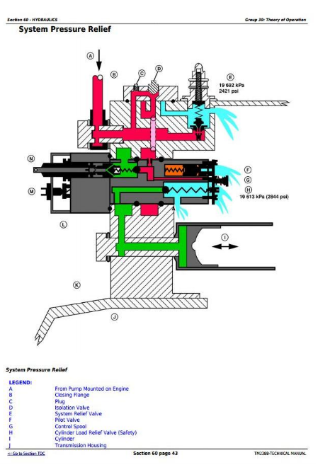
System Pressure Relief
Speed Control Valve - Neutral
Rockshaft Control Valve - Raise
Rockshaft Control Valve - Lower
Rockshaft - Neutral
Group 35: Tests and Adjustments
Hydraulic Warmup Procedure
Rockshaft Position Feedback Linkage Adjustment (Rockshaft Travel Limit)
Rate of Drop/Stop Valve Adjustment
Rockshaft Lift Cycle Test
Rockshaft Leakage Test
System Relief Pressure Test
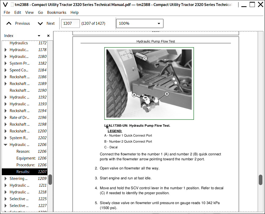
Hydraulic Pump Flow Test
Steering System Relief Pressure Test
Group 40: Repair
Hydraulic Pump Removal and Installation - Export
Selective Control Valve (SCV) Removal and Installation
Selective Control Valve (SCV) Distribution Lines Assembly Removal and Installation
Selective Control Valve (SCV) Disassembly and Assembly
Rockshaft Assembly Removal and Installation
Lift Arms and Rockshaft, Removal and Installation
Rockshaft Control Valve Removal and Installation
Rockshaft Control Valve Linkage Removal and Installation
Rockshaft Piston Removal and Installation
Divider Valve Removal and Installation
Divider Valve Disassembly and Assembly
Rate-of-Drop Valve and Adjuster Removal and Installation
Slow Return Valve Removal and Installation
Rockshaft Safety Valve Removal and Installation
Relief Valve Removal and Installation
Transmission Filter Removal and Installation
Mid Rockshaft Removal and Installation
Section 70: Steering
Group 05: Specifications
Specifications
Service Equipment and Tools
Group 10: Component Location
Steering System Components
Steering System Schematic
Group 15: Theory of Operation
Steering Operation
Group 20: Diagnostics
Steering
Noise
Steering Components
Group 25: Tests and Adjustments
Steering System Test
Group 30: Repair
Tie Rod Removal and Installation
Steering Cylinder Removal and Installation
Steering Wheel Removal and Installation
Steering Control Unit (SCU) Removal and Installation
Section 80: Brakes
Group 05: Specifications
Specifications
Group 10: Component Location
Brake Pedals and Linkage
Brake Pedal and Park Brake Components - Explode
Brake Pedal Components (Export)
Park Brake Components (Export)
Brake Housing Components
Group 15: Theory of Operation
Brakes
Group 20: Diagnostics
Brakes
Brake Check Points
Group 25: Tests and Adjustments
Brake Pedal Adjustment
Park Brake Adjustment - Export
Group 30: Repair
Brake Disassembly and Inspection
Brake Assembly
Brake Pedal Removal and Installation
Park Brake Linkage Removal and Installation
Park Brake Linkage Removal and Installation - (Export)
Section 90: Miscellaneous
Group 05: Specifications
3-Point Hitch
Capacities
Ground Speed
Group 10: Repair
Hood Removal and Installation
Control Panel Removal and Installation
Control Panel Lower Shroud Removal and Installation
Foot Rest Removal and Installation
Battery Removal and Installation
Front Wheel Removal and Installation
Rear Wheel Removal and Installation
Fuel Tank Removal and Installation
Seat and Seat Frame Removal and Installation
Roll Over Protection System Removal and Installation
Rear Fenders Removal and Installation
Fender/ROPS Support Removal and Installation
Three-Point Hitch Removal and Installation
John Deere 2320 Compact Utility Tractor Service Technical Manual (TM2388)
![]()