
John Deere 1654, 1854, 2054, 2104, 6165J, 6185J, 6205J, 6210J Tractors Diagnosis & Tests Service Manual (TM802219)

John Deere 1654, 1854, 2054, 2104, 6165J, 6185J, 6205J, 6210J Tractors Diagnosis & Tests Service Manual (TM802219)
tm802219 - 1654, 1854, 2054, 2104, 6165J, 6185J, 6205J and 6210J Tractors Diagnostic Technical Manual.pdf
Complete Diagnosis and Tests technical manual with electrical wiring diagrams for John Deere Tractors JD1654, JD1854, JD2054, JD2104, 6165J, 6185J, 6205J & 6210J 2WD / MFWD, with all the shop information to maintain, diagnose, rebuild like professional mechanics.
John Deere 1654, 1854, 2054, 2104, 6165J, 6185J, 6205J, 6210J Tractors workshop Operation and Tests manual includes:
* Numbered table of contents easy to use so that you can find the information you need fast.
* Detailed sub-steps expand on repair procedure information
* Numbered instructions guide you through every repair procedure step by step.
* Troubleshooting and electrical service procedures are combined with detailed wiring diagrams for ease of use.
* Notes, cautions and warnings throughout each chapter pinpoint critical information.
* Bold figure number help you quickly match illustrations with instructions.
* Detailed illustrations, drawings and photos guide you through every procedure.
* Enlarged inset helps you identify and examine parts in detail.
Total Pages: 1,941 pages
File Format: PDF (bookmarked, ToC, Searchable, Printable, high quality)
Language: English
MAIN SECTIONS
Foreword
General Information
Safety Information
General References
Diagnostic Trouble Codes
BCU Diagnostic Trouble Codes
ECU Control Unit
Observable Symptoms
Electrical System
Electronic Control Units
PowrQuad Transmissions
Drive Systems
Steering and Brakes
Hydraulic System
Operator's Cab
System Diagnosis
Electronics
Hydraulic System
Engine
General Information
Operational Checks
Tests and Adjustments
Fuel, Air Intake and Cooling Systems
Tests and Adjustments
Fuel System
Air Intake System
Cooling System
Cold-Weather Starting Aids
Electrical System
Fuse Box
Starting and Charging Circuit
CAN BUS and Service Connector
ECU - Power
ECU - Throttle and Fuel System
ECU - Fuel Preheater and Aid Heater
ECU - Sensors
BCU - Electronic Hitch-Control
BCU - Brakes
BCU - PTO
BCU - Front-Wheel Drive
BCU - Differential Lock
BCU - Hall Sending Unit Speedmeter
BCU - Turn Signal and Hazard Warning Lights
Panel Warning Lights
Lights, Tail Lights and License Plate
Work Lights
Radio, Dome Light, Console Light and Beacon Light
Horn and Accessories Socket
Power Outlet
Seat Compressor and Cigarette Lighter
Fan and A/C
Front Windshield Wiper and Washer
Rear Windshield Wiper and Washer
Trailer Connector
Wiring Harnesses
Connectors
Electronic Control Units
Operation and General Information on Diagnostics
Interactive Tests
Interactive Calibrations
Information on How to Reprogram Control Units
Data BUS Systems, Operation
BCU - Basic Control Unit
ECU Control Unit
PowrQuad Transmissions
Operational Check
Tests and Adjustments
Operation
Range Box
Drive Systems
Operational Check
Tests and Adjustments
Operation
Steering and Brakes
Preliminary Checks
Operational Check
Tests and Adjustments
Hydrostatic Steering
Brakes
Air brake system
Hydraulic System
Operational Check
Tests and Adjustments
Theory of operation
Oil Filter, Charge Pump and Hydraulic Pump
Hitch
Selective control valves (SCV)
Hydraulic block
Operator's Cab
Tests and Adjustments
Operation
Special Tools (Dealer-Fabricated)
Special Tools (Dealer-Fabricated)
Special Tools (Available as Spare Parts)
tm802219 - 1654, 1854, 2054, 2104, 6165J, 6185J, 6205Jand 6210JTractors Diagnostic
Table of Contents
Foreword
Section 210: General Information
Group 05: Safety Information
Recognize Safety Information
Follow Safety Instructions
Replace Safety Signs
Wear Protective Clothing
Prevent Battery Explosions
Service Tires Safely
Keep ROPS Installed Properly
Park Machine Safely
Handle Fluids Safely—Avoid Fires
Handle Fuel Safely—Avoid Fires
Prepare for Emergencies
Work in Clean Area
Prevent Machine Runaway
Work In Ventilated Area
Avoid High-Pressure Fluids
Use Proper Lifting Equipment
Illuminate Work Area Safely
Use Proper Tools
Live With Safety
Safety Measures on Electronic Control Units
Group 15: General References
General References—Summary of References
Unified Inch Bolt and Cap Screw Torque Values
Metric Bolt and Cap Screw Torque Values
Hydraulic System Unified Inch Fitting Torques
Hydraulic system metric fitting torques
Component Identification Table
How to use an Electrical Diagram
Electrical Diagram Symbols
Wire Numbers and Color Codes
Troubleshooting Unsolved Problems
Electrical System Visual Inspection
Circuit Malfunctions
Seven Steps Electrical Test Procedure
Hydraulic System — Circuit Symbols
Electrical System, Worksheet for Circuit/Harness Test
Section 211: Diagnostic Trouble Codes
Group BCU: BCU Diagnostic Trouble Codes
BCU 000084.02 - B09 - Hall Sending Unit Speedmeter, out of Valid Range
BCU 000168.03 - Control Unit, Supply Voltage Too High
BCU 000168.04 - Control Unit, Supply Voltage Too Low
BCU 000168.16 - Control Unit, Supply Voltage Too High (Engine Speed Above 500 rpm)
BCU 000168.17 - Control Unit, Supply Voltage Too Low (Engine Speed Above 1500 rpm)
BCU 000168.18 - Control Unit, Supply Voltage Too Low (Engine Speed Above 500 rpm)
BCU 000177.18 - Non-Existent Function Activated
BCU 000186.02 - B06 - Sensor for Rear PTO Speed, Open Circuit
BCU 000186.15 - B06 - Rear PTO Speed Sensor, Speed Present Despite Rear PTO Being Switched Off
BCU 000186.17 - B06 - Rear PTO Speed Sensor, Speed Not Present
BCU 000190.02 - Non-Existent Function Activated
BCU 000237.02 - VIN Information, Mismatch
BCU 000237.14 - VIN Information, System De-Activated
BCU 000237.31 - VIN Information, Incorrect
BCU 000629.12 - Control Unit Internal Fault
BCU 000639.12 - Vehicle CAN BUS, High Error Rate
BCU 000639.14 - Vehicle CAN BUS, Very High Error Rate
BCU 000746.31 - Y05 - Differential Lock Solenoid Valve, Fault
BCU 000980.07 - S21 - Rear PTO Switch, Fault
BCU 001058.18 - Non-Existent Function Activated
BCU 001079.03 - 5-volt Power Supply, Voltage Too High
BCU 001079.04 - 5-volt Power Supply, Voltage Too Low
BCU 001873.03 - B21 - Hitch Position Sensor, Voltage Too High
BCU 001873.04 - B21 - Hitch Position Sensor, Voltage Too Low
BCU 001873.15 - B21 - Hitch Position Sensor, Voltage Too High During Calibration
BCU 001873.17 - B21 - Hitch Position Sensor, Voltage Too Low During Calibration
BCU 001882.02 - Non-Existent Function Activated
BCU 001882.15 - Non-Existent Function Activated
BCU 001882.17 - Non-Existent Function Activated
BCU 001883.31 - Rear PTO Speed Too High
BCU 001890.03 - Non-Existent Function Activated
BCU 001890.04 - Non-Existent Function Activated
BCU 001890.31 - Non-Existent Function Activated
BCU 001893.07 - Non-Existent Function Activated
BCU 001894.31 - INFORMATION FOR OPERATOR: Rear PTO Switch was On When Engine was Started
BCU 002000.09 - Incorrect CAN BUS Message, Information from ECU
BCU 002392.31 - Non-Existent Function Activated
BCU 002818.31 - Non-Existent Function Activated
BCU 002876.07 - S08 - Turn signal switch, Fault (Turn Signal)
BCU 303053.03 - B26 - Sensitivity Potentiometer, Signal Voltage Too High During Calibration
BCU 303053.04 - B26 - Sensitivity Potentiometer, Signal Voltage Too Low During Calibration
BCU 303054.03 - B27 - Depth-Setting Potentiometer, Signal Voltage Too High During Calibration
BCU 303054.04 - B27 - Depth-Setting Potentiometer, Signal Voltage Too Low During Calibration
BCU 303056.03 - B27 - Raise-Limit Potentiometer, Signal Voltage Too High During Calibration
BCU 303056.04 - B27 - Raise-Limit Potentiometer, Signal Voltage Too Low During Calibration
BCU 303057.03 - B27 - Rate-of-Drop Potentiometer, Signal Voltage Too High During Calibration
BCU 303057.04 - B27 - Rate-of-Drop Potentiometer, Signal Voltage Too Low During Calibration
BCU 522451.03 - Non-Existent Function Activated
BCU 522451.04 - Non-Existent Function Activated
BCU 522451.14 - Non-Existent Function Activated
BCU 522507.31 - Control Unit Not Calibrated
BCU 523438.02 - Control Unit Internal Fault
BCU 523652.02 - Control Unit Connected to Wrong Harness Connector
BCU 523689.31 - S22 - Differential Lock Switch, Fault
BCU 523690.02 - S68 - Switches for Remote Control of Hitch (Left), Fault
BCU 523701.05 - M08 - Stepper Motor for Hitch (Coil 2), Open Circuit
BCU 523701.06 - M08 - Stepper Motor for Hitch (Coil 2), Current Too High
BCU 523702.14 - VIN Information, System De-Activated
BCU 523702.31 - VIN Information, Incorrect
BCU 523703.02 - B41 - Draft Sensor, Distorted Signal During Calibration
BCU 523703.03 - B41 - Draft Sensor, Voltage Too High During Calibration
BCU 523703.04 - B41 - Draft Sensor, Voltage Too Low During Calibration
BCU 523703.15 - B41 - Draft Sensor, Voltage Too High
BCU 523703.17 - B41 - Draft Sensor, Voltage Too Low
BCU 523704.02 - Non-Existent Function Activated
BCU 523704.03 - Non-Existent Function Activated
BCU 523704.04 - Non-Existent Function Activated
BCU 523704.15 - Non-Existent Function Activated
BCU 523704.17 - Non-Existent Function Activated
BCU 523751.05 - M08 - Stepper Motor for Hitch (Coil 1), Open Circuit
BCU 523751.06 - M08 - Stepper Motor for Hitch (Coil 1), Current Too High
BCU 523753.16 - M08 - Stepper Motor for Hitch, Raising Deadband Too High During Calibration
BCU 523753.18 - M08 - Stepper Motor for Hitch, Raising Deadband Too Low During Calibration
BCU 523756.16 - M08 - Stepper Motor for Hitch, Lowering Deadband Too High During Calibration
BCU 523756.18 - M08 - Stepper Motor for Hitch, Lowering Deadband Too Low During Calibration
BCU 523758.11 - Non-Existent Function Activated
BCU 523759.11 - Non-Existent Function Activated
BCU 523760.04 - Turn Signal/Hazard Flasher System, Supply Voltage Too Low
BCU 523760.31 - Turn Signal/Hazard Flasher System, Fault
BCU 523826.03 - Non-Existent Function Activated
BCU 523826.04 - Non-Existent Function Activated
BCU 523834.03 - B27 - Depth-Setting Potentiometer, Voltage Too High
BCU 523834.04 - B27 - Depth-Setting Potentiometer, Voltage Too Low
BCU 523839.31 - Non-Existent Function Activated
BCU 523843.02 - S24 - Quick Withdrawal Switch, Switch Status out of Valid Range
BCU 523843.03 - S24 - Quick Withdrawal Switch, Voltage Too High
BCU 523843.04 - S24 - Quick Withdrawal Switch, Voltage Too Low
BCU 523904.31 - Non-Existent Function Activated
BCU 523905.31 - Non-Existent Function Activated
BCU 523908.14 - Non-Existent Function Activated
BCU 523908.31 - Non-Existent Function Activated
BCU 524055.11 - Control Unit Internal Fault
BCU 524055.31 - Control Unit Not Calibrated
BCU 524216.14 - Non-Existent Function Activated
BCU 524216.31 - Non-Existent Function Activated
BCU 524224.14 - Non-Existent Function Activated
BCU 524224.31 - INFORMATION FOR OPERATOR: Rear PTO was Switched On When Engine Was Started
BCU 524235.02 - Non-Existent Function Activated
BCU 524235.31 - Y03 - Front-Wheel Drive Solenoid Valve, Fault
BCU 524252.31 - Y04 - Solenoid Valve for Rear PTO, Fault
Group ECU: ECU Control Unit
ECU 000029.03 - B96 - Hand Throttle Potentiometer, Voltage Too High
ECU 000029.04 - B96 - Hand Throttle Potentiometer, Voltage Too Low
ECU 000084.31 - Incorrect CAN BUS Message, Wheel Speed from BCU
ECU 000091.03 - B79 - Accelerator Pedal Potentiometer, Voltage Too High
ECU 000091.04 - B79 - Accelerator Pedal Potentiometer, Voltage Too Low
ECU 000097.03 - Water In Fuel Signal Out of Range
ECU 000097.04 - Water In Fuel Signal Out of Range Low
ECU 000097.16 - Water In Fuel Detected
ECU 000105.00 - Manifold Air Temperature Signal Extremely High
ECU 000105.03 - Manifold Air Temperature Signal Out of Range High
ECU 000105.04 - Manifold Air Temperature Signal Out of Range Low
ECU 000105.15 - Manifold Air Temperature Signal Slightly High
ECU 000105.16 - Manifold Air Temperature Signal Moderately High
ECU 000108.02 - Barometric Air Pressure Signal Invalid
ECU 000110.00 - Coolant Temperature Signal Extremely High
ECU 000110.03 - Coolant Temperature Signal Out of Range High
ECU 000110.04 - Coolant Temperature Signal Out of Range Low
ECU 000110.15 - Coolant Temperature Signal Slightly High
ECU 000110.16 - Engine Coolant Temperature Moderately High
ECU 000157.03 - Fuel Rail Pressure Signal Out of Range High
ECU 000157.04 - Fuel Rail Pressure Signal Out of Range Low
ECU 000157.10 - Fuel Rail Pressure Loss Detected
ECU 000157.17 - Fuel Rail Pressure Not Developed
ECU 000158.17 - ECU Power Down Error
ECU 000160.02 - Wheel Speed Signal Incorrect
ECU 000174.00 - Fuel Temperature Signal Extremely High
ECU 000174.03 - Fuel Temperature Signal Out of Range High
ECU 000174.04 - Fuel Temperature Signal Out of Range Low
ECU 000174.16 - Fuel Temperature Signal Moderately High
ECU 000189.00 - Engine Speed Derate Condition Exists
ECU 000190.00 - Engine Speed Extremely High
ECU 000190.16 - Engine Overspeed Moderate
ECU 000237.02 - VIN Information, Mismatch
ECU 000237.13 - VIN Option Code Invalid
ECU 000237.31 - VIN Information, Incorrect
ECU 000611.03 - Injector Shorted to Voltage Source
ECU 000611.04 - Injector Shorted to Ground
ECU 000627.01 - All Injector Circuits Have High Resistance
ECU 000629.12 - ECU EEPROM Error
ECU 000629.13 - ECU Boot Block Error
ECU 000636.02 - Camshaft Position Signal Invalid
ECU 000636.05 - Camshaft Position Circuit Has High Resistance
ECU 000636.06 - Camshaft Position Circuit Has Low Resistance
ECU 000636.08 - Camshaft Position Signal Missing
ECU 000636.10 - Camshaft Position Signal Rate of Change Abnormal
ECU 000637.02 - Crankshaft Position Signal Invalid
ECU 000637.05 - Crankshaft Position Circuit Has High Resistance
ECU 000637.06 - Crankshaft Position Circuit Has Low Resistance
ECU 000637.07 - Crankshaft and Camshaft Position Signals Out of Sync
ECU 000637.08 - Crankshaft Position Signal Missing
ECU 000637.10 - Crankshaft Position Signal Rate of Change Abnormal
ECU 000651.02 - Injector #1 Part Number Invalid
ECU 000651.05 - Injector #1 Circuit Has High Resistance
ECU 000651.06 - Injector #1 Circuit Has Low Resistance
ECU 000651.07 - Injector #1 Not Responding
ECU 000651.13 - Injector #1 Calibration Fault
ECU 000652.02 - Injector #2 Part Number Invalid
ECU 000652.05 - Injector #2 Circuit Has High Resistance
ECU 000652.06 - Injector #2 Circuit Has Low Resistance
ECU 000652.07 - Injector #2 Not Responding
ECU 000652.13 - Injector #2 Calibration Fault
ECU 000653.02 - Injector #3 Part Number Invalid
ECU 000653.05 - Injector #3 Circuit Has High Resistance
ECU 000653.06 - Injector #3 Circuit Has Low Resistance
ECU 000653.07 - Injector #3 Not Responding
ECU 000653.13 - Injector #3 Calibration Fault
ECU 000654.02 - Injector #4 Part Number Invalid
ECU 000654.05 - Injector #4 Circuit Has High Resistance
ECU 000654.06 - Injector #4 Circuit Has Low Resistance
ECU 000654.07 - Injector #4 Not Responding
ECU 000654.13 - Injector #4 Calibration Fault
ECU 000655.02 - Injector #5 Part Number Invalid
ECU 000655.05 - Injector #5 Circuit Has High Resistance
ECU 000655.06 - Injector #5 Circuit Has Low Resistance
ECU 000655.07 - Injector #5 Not Responding
ECU 000655.13 - Injector #5 Calibration Fault
ECU 000656.02 - Injector #6 Part # Data Invalid
ECU 000656.05 - Injector #6 Circuit Has High Resistance
ECU 000656.06 - Injector #6 Circuit Has Low Resistance
ECU 000656.07 - Injector #6 Not Responding
ECU 000656.13 - Injector #6 Calibration Fault
ECU 000676.03 - Glow Plug Relay Voltage Too High
ECU 000676.05 - Glow Plug Relay Voltage Too Low
ECU 001069.31 - Tire Size Error
ECU 001347.03 - Suction Control Valve Signal Out of Range High
ECU 001347.05 - Suction Control Valve Circuit Has High Resistance
ECU 001347.07 - Fuel Rail Pressure Actual to Desired Mismatch
ECU 001569.31 - Engine in Power Derate Condition
ECU 002033.09 - Incorrect CAN BUS Message, CAN Message from BCU
ECU 002033.14 - Communication Problem between ECU and BCU
ECU 002033.19 - Communication Problem between ECU and BCU
ECU 003509.03 - Sensor Supply #1 Voltage Out of Range High
ECU 003509.04 - Sensor Supply #1 Voltage Out of Range Low
ECU 003510.03 - Sensor Supply Voltage 2 Too High
ECU 003510.04 - Sensor Supply Voltage 2 Too Low
ECU 003511.03 - Sensor Supply Voltage 3 Too High
ECU 003511.04 - Sensor Supply Voltage 3 Too Low
Section 212: Observable Symptoms
Group 40: Electrical System
Control Unit(s) Not Displayed
Diagnostic Mode Cannot Be Entered or Connection Problems with Service ADVISOR (Cab Tractors)
Problems with the CAN-BUS Connection to Service ADVISOR
Problems with the Battery
Problems with the Starter Motor
Problems with the Fuel Preheater, Aid Heater and Fuel Pump
Problems with the Instrument Unit
Problems with the Horn
Problems with Cigarette Lighter (E05)
Problems with Seat with Compressor and Heater (A29)
Problems with the Parking Lights
Problems with Low-Beam Headlights
Problems with High-Beam Headlights
Problems with the Worklights on Front of Roof
Problems with the Worklights on Rear of Roof
Problems with the Radio
Problems with the Air-Conditioning System and/or with the Fan
Problems with the Front Windshield Wiper
Problems with the Front Windshield Washer
Problems with the Rear Windshield Wiper
Problems with the Rear Windshield Washer
Problems with the Beacon Light
Group 45: Electronic Control Units
Problems when Programming the BCU Control Unit
Problems when Programming the ECU Control Unit
Problem with the BCU Control Unit
Problem with the Instrument Unit (Adjustment)
Group 55: PowrQuad Transmissions
Problems with PowrQuad Transmission
Group 56: Drive Systems
Problems with the PTO
Group 60: Steering and Brakes
Problems with the Brakes
Problems with the Steering
Group 70: Hydraulic System
Problems with the Rockshaft
Problems with the Rockshaft's Remote Control
Group 90: Operator's Cab
Problems with the Air-Conditioning System
Section 213: System Diagnosis
Group 45: Electronics
29-bit CAN BUS - Check (Cab Tractors)
VIN Security Fault Diagnosis
Group 70: Hydraulic System
Check for PFC Hydraulic System
Section 220: Engine
Group 05: General Information
Information on Engine
Group 10: Operational Checks
Engine - Safety Measures
Engine - Preliminary Engine Tests
Group 15: Tests and Adjustments
Engine - Tune-Up, Summary of References
Engine - Measuring PTO Power Output
Engine - Engine Tests with Service ADVISOR
Section 230: Fuel, Air Intake and Cooling Systems
Group 15: Tests and Adjustments
Fuel, Air Intake and Cooling Systems - Tests and Adjustments, Summary of References
Fuel, Air Intake and Cooling Systems - General Information
Fuel, Air Intake and Cooling Systems - Explanation of Checks
Fuel, Air Intake and Cooling Systems - Safety Measures
Fuel, Air Intake and Cooling Systems - Special Tools, Summary of References
Fuel, Air Intake and Cooling Systems - Specifications
Air Intake System - System Check
Cooling System - Filling/Bleeding the System
Cooling System - Leak Test
Cooling System - Test Thermostat Opening Temperature
Cooling System - Flow Testing in the Low-Temperature Circuit
Cooling System - Check the Viscous Fan Drive
Fuel System - Check the Fuel Transfer Pump
Group 20A: Fuel System
Fuel System - Theory of Operation, Summary of References
Fuel System - Theory of Operation
Fuel System - Fuel Cooler, Component Information
Fuel System - Fuel Transfer Pump, Component Information
Group 20B: Air Intake System
Air Intake System - Theory of Operation, Summary of References
Air Intake System - Theory of Operation
Group 20C: Cooling System
Cooling System - Summary of References
Coolant Circuit - Description
Cooling System Radiator - Description
Itercooler - Description
Ring-Shaped (Transmission Oil) Cooler - Description
Automatic Drive Belt Tensioner - Theory of Operation
Group 20D: Cold-Weather Starting Aids
Cold-Weather Starting Aids - Summary of References
Cold-Weather Starting Aids - General Information
Cold-Weather Starting Aids - Coolant Heater - Component Information
Cold-Weather Starting Aids - Transmission Oil Heater - Component Information
Cold-Weather Starting Aids - Charge Pump Preheater - Component Information
Section 240: Electrical System
Group 05A: Fuse Box
Fuse Box - Theory of Operation
Fuse Box - Electrical Diagram
Group 05B: Starting and Charging Circuit
Starting and Charging Circuit - Theory of Operation
Starting and Charging Circuit - Electrical Diagram
Circuit test for Starter motor checks (M01)
Circuit test for Alternator (G02)
Circuit test for Battery (G01)
Circuit test for K01 Starter relay
Group 05C: CAN BUS and Service Connector
CAN BUS System - Theory of Operation
CAN BUS System - Electrical Diagram
Group 05D: ECU - Power
ECU Power - Theory of Operation
ECU Power - Electrical Diagram
Group 05E: ECU - Throttle and Fuel System
ECU Throttle and Fuel System - Theory of Operation
ECU Throttle and Fuel System - Electrical Diagram
Circuit test for Foot throttle (B79)
Circuit test for Electrical hand throttle (B96)
Group 05F: ECU - Fuel Preheater and Aid Heater
ECU Fuel Preheater and Aid Heater - Theory of Operation
ECU Fuel Preheater and Aid Heater - Electrical Diagram
Circuit test for Fuel Pump (M31)
Circuit test for Heating Element of Fuel Preheater (R02)
Circuit test for Sender for Electrical starting aid heater (R15)
Group 05G: ECU - Sensors
ECU Sensors - Theory of Operation
ECU Sensors - Electrical Diagram
Circuit test for Engine Speed Sender (B72)
Group 05H: BCU - Electronic Hitch-Control
BCU - Electronic Hitch-Control - Theory of Operation
BCU - Electronic Hitch-Control - Electrical Diagram
Circuit test for Rockshaft Control Stepper Motor (M08)
Circuit test for Sensitivity Potentiometer (B26)
Circuit test for Depth-setting Potentiometer (R08)
Circuit test for Rate-of-Drop Potentiometer (R06)
Circuit test for Raise-Limit Potentiometer (R07)
Circuit test for Position Sensor (B21)
Circuit test for Position Sensor (B41)
Circuit/harness test for Rapid Raise Switch (S24)
Circuit test for Left Remote Control Switch (S68)
Circuit test for Supply Voltage for 5-Volt BCU Components
Group 05I: BCU - Brakes
BCU - Brakes - Theory of Operation
BCU - Brakes - Electrical Diagram
Circuit test for Brake Pedal Sensor Unit (B88)
Group 05J: BCU - PTO
BCU - PTO - Theory of Operation
BCU - PTO - Electrical Diagram
Circuit test for PTO Switch (S21)
Circuit test for PTO Solenoid Valve (Y04)
Circuit test for Rear PTO Speed Sensor (B06)
Group 05K: BCU - Front-Wheel Drive
BCU - Front-Wheel Drive - Theory of Operation
BCU - Front-Wheel Drive - Electrical Diagram
Circuit test for Front-Wheel Drive Switch (S63)
Circuit test for Front-Wheel Drive Solenoid Valve (Y03)
Group 05L: BCU - Differential Lock
BCU - Differential Lock - Theory of Operation
BCU - Differential Lock - Electrical Diagram
Circuit test for Differential Lock Switch (S22)
Circuit test for Differential Lock Solenoid Valve (Y05)
Group 05M: BCU - Hall Sending Unit Speedmeter
BCU Hall Sending Unit Speedmeter - Theory of Operation
BCU Hall Sending Unit Speedmeter - Electrical Diagram
Circuit test for Hall Sending Unit Speedmeter (B09)
Group 05N: BCU - Turn Signal and Hazard Warning Lights
BCU - Turn Signal and Hazard Warning Lights - Theory of Operation
BCU - Turn Signal and Hazard Warning Lights - Electrical Diagram
Circuit test for hazard warning switch (S106)
Circuit test for Turn Signal Switch (S08)
Group 05O: Panel Warning Lights
Panel Warning Lights - Theory of Operation
Panel Warning Lights - Electrical Diagram
Circuit test for Sender for air cleaner restriction warning light (B02)
Circuit test for Fuel gauge sender (B03)
Circuit test for Engine oil pressure sender (B04)
Circuit test for Sender for the transmission oil filter sender (B07)
Circuit test for Coolant temperature sender (B08)
Circuit test for Transmission oil pressure sender (B31)
Circuit test for Transmission oil temperature sender (B29)
Group 05P: Lights, Tail Lights and License Plate
Lights and Tail Lights - Theory of Operation
Lights and Tail Lights - Electrical Diagram
Lighting Circuits
Group 05Q: Work Lights
Work Lights - Theory of Operation
Work Lights - Electrical Diagram
Work lights
Group 05R: Radio, Dome Light, Console Light and Beacon Light
Radio, Dome Light, Console Light and Beacon Light - Theory of Operation
Radio, Dome Light, Console Light and Beacon Light - Electrical Diagram
Circuit test for Radio (A60 - Radio Circuits)
Circuit test forDome Light (A08)
Circuit test for Beacon light (E27)
Group 05S: Horn and Accessories Socket
Horn and Accessories Socket - Theory of Operation
Horn and Accessories Socket - Electrical Diagram
Circuit test for Horn (H01)
Group 05T: Power Outlet
Power Outlet - Theory of Operation
Power Outlet - Electrical Diagram
Group 05U: Seat Compressor and Cigarette Lighter
Seat Compressor and Cigarette Lighter - Theory of Operation
Seat Compressor and Cigarette Lighter - Electrical Diagram
Seat and Cigarette lighter System
Group 05V: Fan and A/C
Fan and A/C - Theory of Operation
Fan and A/C - Electrical Diagram
Fan, Air Conditioning and Automatic A/C control
Group 05W: Front Windshield Wiper and Washer
Front Windshield Wiper and Washer - Theory of Operation
Front Windshield Wiper and Washer - Electrical Diagram
Front Windshield Wiper and Washer System
Group 05X: Rear Windshield Wiper and Washer
Rear Windshield Wiper and Washer - Theory of Operation
Rear Windshield Wiper and Washer - Electrical Diagram
Rear Windshield Wiper and Washer System
Group 05Y: Trailer Connector
Trailer Connector - Theory of Operation
Trailer Connector - Electrical Diagram
Group 10: Wiring Harnesses
Disconnecting Electrical Circuits
Location of Ground Points
Removing and Installing Wiring Harness W01 — Power link Box
Removing and Installing Wiring Harness W02 — Engine Wiring Harness (Cab Tractors)
Removing and Installing Wiring Harness W04 — Headlights
Removing and Installing Wiring Harness W08 — (Cab Tractors)
Removing and Installing Wiring Harness W09 — Hood (Cab Tractors)
Removing and Installing Wiring Harness W19 — Cab Roof
Removing and Installing Wiring Harness W26 — Fan and Air Conditioning
Removing and Installing Wiring Harness W28 — Front End of Transmission (Cab Tractors)
Removing and Installing Wiring Harness W30 — Rear End of Transmission (Cab Tractors)
Wiring Harness W31 — Power Take-Off for 7-Pin Socket
Group 15: Connectors
Connectors - Summary of References
A01 - Fuse and relay box
A02 - Fuse Box 2
A03 - Fuse Box 3
A04 - Fuse Box 4
A05 - Fuse Box 5
A06 - Power Link Box
A08 - Dome Light
A29 - Pneumatic operator's seat and rear wiper
A60 - Radio
A62 - Bus terminator
A84 - Bus terminator engine
B02 - Sender for air cleaner restriction warning light
B03 - Fuel gauge sensor unit
B04 - Sender for engine oil pressure indicator light
B06 - Rear PTO Speed Sensor
B07 - Transmission oil filter pressure sensor - Without AutoTrac™ Integrated
B08 - Coolant temperature sensor
B09 - Hall Sending Unit Speedmeter
B14 - Compressor and thermostat switch
B15 - Air conditioning system pressure switch
B21 - Hitch-control position sensor
B26 - Sensitivity potentiometer
B27 - Feedback unit
B29 - Transmission oil temperature sensor
B30 - Hydrostatic oil temperature sensor
B31 - Transmission oil pressure sender
B36 - Neutral start switch
B37 - Interface handbrake
B41 - Draft potentiometer
B56 - Water temperature engine sensor
B59 - Manifold air temperature sensor
B72 - Crankshaft speed sensor
B74 - Event sensor
B79 - Foot throttle
B88 - Brake switch
B96 - Electrical hand throttle
B114 - Fuel temperature sensor
B121 - Water in fuel sensor
B137 - Fuel rail pressure sensor
E01 - Right-hand front light
E02 - Left-hand front light
E05 - Cigarette lighter
E09-R - Right-hand front working light
E09-L - Left-hand front working light
E11-1 - Right-hand rear working light
E11-2 - Left-hand rear working light
E12-2 - Console light
E27 - Beacon light
G01 - Battery
G02 - Alternator
H01 - Horn
H77 - Aid heater indicator light
K01 - Starter relay
M01 - Starter motor
M02 - Air conditioning compressor
M03 - Wiper motor
M04 - Wiper motor
M05 - Windshield washer pump
M06 - Windshield washer pump
M07 - Fan motor
M08 - Hitch-control stepper motor
M10 - Fan motor
M31 - Fuel pump
R02 - Fuel preheater
R03 - Resistors
R15 - Electrical starting aid heater
S01 - Starter switch
S04 - Horn switch
S08 - Turn signal switch
S09 - Light switch
S10 - Full/low beam light switch
S14 - Fan switch
S15 - Windshield wiper switch
S18 - Rear wiper switch
S20 - Windshield switch
S21 - PTO switch
S22 - Differential lock switch
S36 - Beacon light switch
S63 - Front-wheel drive switch
S68 - External hitch-control switch
S92-2 - Rear work lights switch
S106 - Hazard warning lights switch
W25 - Radio antenna
X05 - Trailer connector
X25 - Instrument right panel connector
X26 - Instrument left panel connector
X37 - Accessories socket
X40 - Connector (W22 and W23)
X42 - Connector (W21 and W22)
X106 - Tail, brake and turn signal lights (right-hand)
X107 - Tail, brake and turn signal lights (left-hand)
X108 - Front right- hand turn signal light
X109 - Front left-hand turn signal light
X113 - License Light Connector
X182 - Connector (W08 and W26)
X234 - Connector (W30 and W31)
X239 - Outlet Socket Connector
X305 - Cooler grounding
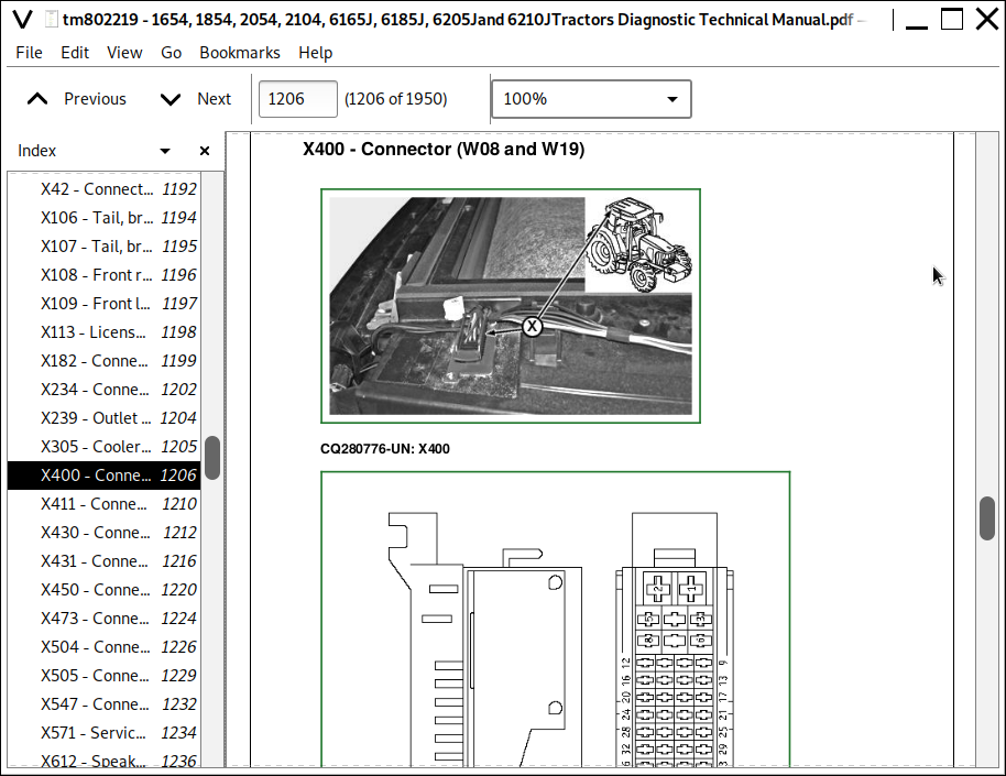
X400 - Connector (W08 and W19)
X411 - Connector (W02 and W04)
X430 - Connector (W08 and W30)
X431 - Connector (W08 and W28)
X450 - Connector (W02 and W08)
X473 - Connector (W01 and W08)
X504 - Connector (W08 and W09)
X505 - Connector (W08 and W09)
X547 - Connector (W02 and W03)
X571 - Service connector (CAN Bus)
X612 - Speaker connector
X616-1 Basic control unit (BCU)
X616-2 Basic control unit (BCU)
X616-3 Basic control unit (BCU)
X844-1 — Engine control unit (ECU)
X844-2 — Engine control unit (ECU)
XGND1 - Cab ground wire
XGND2 - Cab ground wire
XGND5 - Cab ground wire
XGND6 - Rear wiper ground wire
XGND9 - Engine grounding
XGND10 - Cab roof ground wire
XGND14 - Cab roof ground wire
XGND58 - Fan and A/C wiring harness grounding
Y03 - Front-wheel drive solenoid valve
Y04 - PTO Solenoid
Y05 - Differential lock solenoid valve
Y44 - Suction control valve
Y47 - Injection valve
Section 245: Electronic Control Units
Group 05: Operation and General Information on Diagnostics
Operation and General Information - Summary of References
Eletronic Control Units - Special Tools
Operation and General Information on Diagnostics - Abbreviations for Control Units
Operation and General Information on Diagnostics - Instrument Unit Adjustment
Operation and General Information on Diagnostics - Operation and Entering the Program Mode using the Performance Monitor
Operation and General Information on Diagnostics - Procedure for Dealing with Diagnostic Trouble Codes
Operation and General Information on Diagnostics - Accessing Addresses and Diagnostic Trouble Codes
Operation and General Information on Diagnostics - Approved Software for Control Units
Operation and General Information on Diagnostics - Locations and Allocations of Control Units
Group 10A: Interactive Tests
Interactive Tests - Summary of References
Procedure in the Event of Problems with Interactive Tests
BCU: Recording in Debug Mode
BCU: Control Unit Information and Input Addresses - Summary
BCU: BCU Test
ECU: Cylinder Misfire Test
ECU: Compression Test
ECU: Cylinder Cut-Out Test
ECU: Harness diagnostic mode test
ECU: Internal Data Monitor (IDM)
ECU: Communication Error Test
ECU: Control Unit Information and Summary
ECU: Engine Speed Change Test
Group 10B: Interactive Calibrations
Interactive Calibrations - Summary of References
Procedure in the Event of Problems with Interactive Calibration
BCU: Calibrate the Hitch Control
ECU: Calibrate the Electronic Fuel Injectors (Move Injectors to Different Positions or Replace Injectors, and Display Progress of Calibration)
Group 15: Information on How to Reprogram Control Units
Information on How to Program Control Units - Summary of References
General Information on How to Reprogram Control Units
Check and Download Tractor-Specific Software Information
Procedure When Replacing Control Units
Important Notes on Programming
Procedure When Programming Control Units
Procedure in the Event of a Problem Programming Control Units Protected by VIN
Procedure in the Event of a Programming Problem
Group 20: Data BUS Systems, Operation
Data BUS systems - Summary of References
Data BUS Systems - CAN BUS Systems
Data BUS Systems - CAN BUS Systems on Engines with Level 16 Control Unit (2-Valve HPCR Fuel System)
Data BUS systems - Plug Layout
Data BUS systems - Determining the Type of the CAN BUS Fault
Group BCU: BCU - Basic Control Unit
BCU - Summary of References
BCU - Summary of Addresses
BCU - Calibration and Input Addresses
BCU - Summary of Operational Checks
BCU - Theory of Operation (Basic Functions)
BCU - Theory of Operation (Hitch Control)
BCU - CAN BUS Information
Address BCU020 - Input Address, Engine Speed Sensor/Pulses per Engine Revolution
Address BCU021 - Input Address, Rear PTO Speed Sensor/Pulses per PTO Revolution
Address BCU022 - Input Address, Front-Wheel Drive Control Function
Address BCU023 - Vacant Input Address
Address BCU024 - Input Address, Settings for Units of Measurement in Display and for Acoustic Indicator for Turn Signal
Address BCU026 - Vacant Input Address
Address BCU027 - Vacant Input Address
Address BCU028 - Input Address, Rear PTO Present/Not Present
Address BCU029 - Vacant Input Address
Address BCU030 - Input Address, Sensor Diagnostics
Address BCU031 - Vacant Input Address
Address BCU034 - Input Address, Configuration of Instrument Unit and Self-Canceling Turn Signals
Address BCU035 - Input Address, Service Interval Setting
Address BCU041 - Vacant Input Address
Address BCU042 - Vacant Input Address
Address BCU043 - Vacant Input Address
Address BCU045 - Vacant Input Address
Address BCU046 - Input Address, Activate/De-activate Delayed Activation of Alternator
Address BCU047 - Input Address, Delayed Activation of Alternator, Configuration
Address BCU048 - Vacant Input Address
Address BCU049 - Vacant Input Address
Address BCU050 - Vacant Input Address
Address BCU051 - Vacant Input Address
Address BCU052 - Vacant Input Address
Address BCU055 - Input Address, Configuration of Acoustic Alarm
Address BCU056 - Input Address, Tire Configuration
Address BCU058 - Input Address, Sensor for Wheel Speed / Transmission Pulses per Axle Revolution
Address BCU060 - Vacant Input Address
Address BCU063 - Vacant Input Address
Address BCU065 - Vacant Input Address
Address BCU071 - Vacant Input Address
Address BCU073 - Vacant Input Address
Address BCU074 - Vacant Input Address
Address BCU075 - Vacant Input Address
Address BCU077 - Vacant Input Address
Address BCU078 - Vacant Input Address
Address BCU088 - Vacant Input Address
Address BCU089 - Vacant Input Address
Address BCU090 - Vacant Input Address
Address BCU091 - Vacant Input Address
Address BCU092 - Vacant Input Address
Address BCU093 - Vacant Input Address
Address BCU094 - Vacant Input Address
Address BCU097 - Input Address, Low Fuel Level Acoustic Alarm
Address BCU099 - Input Address, Automatic Deletion of Diagnostic Trouble Codes
Address BCU101 - Input Address, Leak-Off Function of Hitch Valve On or Off
Address BCU118 - Input Address, Quick Withdrawal and Hitch Dampening On or Off
Address BCU122 - Hitch Control Calibration
Address BCU138 - Input Address, Leak-off Function of Hitch Valve (Adjusting Stepper Motor Steps)
Address BCU145 - Input Address, Hitch Control On or Off
Address BCU154 - Input Address, Leak-off Function of Hitch Valve (Time Setting)
Address BCU162 - Input Address, Switching Off Hydraulic Oil Temperature Access (During Calibration)
Address BCU165 - Input Address, Raise Rate Setting
Address BCU167 - Input Address, Activate/De-activate Hitch Components
Address BCU174 - Input Address, Index for Load Control
Address BCU247 - Tractor Model Designation
Address BCU248 - Tractor Serial Number
B06 - Rear PTO Speed Sensor, Operational Check
B09 - Hall Sending Unit Speedmeter, Operational Check
B21 - Hitch Position Sensor, Operational Check
B26 - Sensitivity Potentiometer, Operational Check
B27 - Position Feedback Unit for Hitch Control, Operational Check
B41 - Draft Sensor, Operational Check
B88 - Brake Pedal Sensor Unit, Operational Check
M08 - Stepper Motor for Hitch, Operational Check
S08 - Turn Signal Switch, Operational Check
S21 - Rear PTO Switch, Operational Check
S22 - Differential Lock Switch, Operational Check
S24 - Quick Withdrawal Switch, Operational Check
S63 - Front-Wheel Drive Switch, Operational Check
S68 - Switch for Hitch Remote Control (Left), Operational Check
S106 - Hazard Warning Light Switch, Operational Check
Supply Voltage for 5-volt BCU Components, Operational Check
Group ECU: ECU Control Unit
ECU - Summary of References
ECU - Summary of Addresses (Level 16 ECU for 2-Valve Engine with HPCR)
ECU - Calibration and Input Addresses (Level 16 ECU for 2-Valve Engine with HPCR)
ECU - Summary of Operational Checks
ECU - Theory of Operation (Level 16 ECU for 2-Valve Engine with HPCR)
B02 - Air Cleaner Restriction Sensor, Operational Check
B96 - Hand Throttle Potentiometer, Operational Check
B79 - Accelerator Pedal Potentiometer, Operational Check
R15 - Heating Element of Electrical Starting Aid (2-Valve Engine with HPCR), Operational Check
Section 255: PowrQuad Transmissions
Group 10: Operational Check
PowrQuad Transmission—Operational Check
Group 15: Tests and Adjustments
PowrQuad Transmission—Summary of References
PowrQuad Transmission— Special Tools
PowrQuad Transmission—System Check
PowrQuad Transmission—Test Ports
PowrQuad Transmission—Checking Rate of Flow at Cooler
PowrQuad Transmission—Checking the Cooler Relief Valve
PowrQuad Transmission—System Pressure Check
PowrQuad Transmission—Checking Lube Oil Pressure
PowrQuad Transmission—Checking Cooling Oil Pressure (Forward Clutch)
PowrQuad Transmission—Checking Cooling Oil Pressure (Reverse Brake)
PowrQuad Transmission—Checking Pressure at Forward Clutch
PowrQuad Transmission—Checking Pressure at Reverse Brake
PowrQuad Transmission—Checking Pressure at Brake B1
PowrQuad Transmission—Checking Pressure at Brake B2
PowrQuad Transmission—Checking Pressure at Brake B3
PowrQuad Transmission—Checking Pressure at Clutch C4
PowrQuad Transmission—Adjusting System Pressure
PowrQuad Transmission—Test Result Table
PowrQuad Transmission—Adjusting Gear Shift
PowrQuad Transmission—Adjusting Forward/Reverse Cable
PowrQuad Transmission—Adjusting Park Lock
Group 20: Operation
PowrQuad Transmission — Summary of References
PowrQuad Transmission—Layout
PowrQuad Module—Layout
PowrQuad Module—Cross-Sectional and 3D View
PowrQuad Module—Location of Valves, Sensors and Switches
PowrQuad Module—Element Engagement Chart
PowrQuad Module—Pneumatic Pump
PowrQuad Module—Transmission Oil Pump
PowrQuad Module — Pressure-Regulating Valve and Filter Relief Valve
PowrQuad Module—Overspeed Relief Valve and Anti-Cavitation Check Valve
PowrQuad Module—Clutch Cooling Components
PowrQuad Module —Clutch Cooling Valve (Forward/Reverse)
PowrQuad Module—System 1 Oil and System 2 Oil
PowrQuad Module—Hydraulic Schematic, Mechanically Actuated PowrQuad Module
PowrQuad Module—Operation of Forward/Reverse Modulation, Mechanically Actuated PowrQuad Module
PowrQuad Module—Neutral Start Circuit, Mechanically Actuated PowrQuad Module
PowrQuad Module—Operation of Gear-to-Gear Modulation, Mechanically Actuated PowrQuad Module
Group 30: Range Box
Range Transmission — Cross-Sectional View
Section 256: Drive Systems
Group 10: Operational Check
Power train - operational check
Group 15: Tests and Adjustments
Tests and Adjustments—Summary of References
Tests and Adjustments—Special Tools
Drive Systems—System Check
Checking Pressure at the Front-Wheel Drive Clutch
Checking Pressure at the Hydraulic Differential Lock
Checking Pressure at the PTO
Drive Systems—Test Result Table
Group 20: Operation
Drive Systems—Summary of References
Front Wheel Drive Clutch—Cross-Sectional View
Front Wheel Drive Clutch—Oil Flow and Power Flow
Front Wheel Drive Clutch Disengaged—Oil Flow
Differential—Cross-Sectional View
Differential—Power Flows
Differential—Oil Flows
Final Drives—Operation and Cross-Sectional View
PTO Options—Description
PTO Options—PTO Modulating Valve and Solenoid Valve
PTO Options—PTO brake and PTO clutch
PTO Options—Power Flows
Section 260: Steering and Brakes
Group 05: Preliminary Checks
Preliminary Checks—Summary of References
Preliminary Checks – Steering System
Preliminary Checks – Brake System
Group 10: Operational Check
Operational Checkout—Summary of References
Safety Information
Steering Check
Checking Brakes
Group 15: Tests and Adjustments
Tests & Adjustments—Summary of References
Steering and Brakes - Special Tools
Steering and Brakes - Specifications
Checking Steering Valve
Checking Brake System
Bleeding the Rear Brakes
Adjusting Brake Pedals and Switches
Group 20A: Hydrostatic Steering
Description of Steering Valves, Operation
Group 20B: Brakes
Brakes—Summary of Reference
Operation of Brake Piston, Plate and Disks
Brake released
Initial Braking
Brake Engaged
Rear Wheel Brakes, Operation
Group 20C: Air brake system
Steering and Brakes - Air Brakes, Summary of References
Steering and Brakes - Air Brakes, Description
Steering and Brakes - Air Brakes, Compressor
Steering and Brakes - Air Brakes, Pressure Regulating Valve
Steering and Brakes - Air Brakes, Compressed Air Tank
Steering and Brakes - Air Brakes, Trailer Control Valve
Steering and Brakes - Air Brakes, Coupling Ends
Section 270: Hydraulic System
Group 10: Operational Check
Hydraulic System - Operational Check—Summary of References
General Information - Transmission and Hydraulic System, Introductory Checks
Hydraulic System - Load Check
Hitch Control – Operational Check
Hydraulic System - External Control of Hitch, Operational Check-Out
Hydraulic System - Selective Control Valves (M-SCV), Operational Check-Out
Group 15: Tests and Adjustments
Tests and Adjustments—Summary of References
Hydraulic System - Special Tools
Safety Measures for Hydraulic Checks
PFC Hydraulic System - Worksheet for the Hydraulic System Diagnostics
PFC Hydraulic System - Oil Pressure Test Ports
PFC Hydraulic System - Checking and Adjusting the Maximum Load Sense Pressure
PFC Hydraulic System - Check and Adjust System Oil Pressure
PFC Hydraulic System - Check and Adjust Differential Pressure
PFC Hydraulic System - Priority Circuit 1, Checking and Adjusting the Load Sense Oil Pressure for Steering
PFC Hydraulic System - Priority Circuit 3, Checking the Oil Pressure
PFC Hydraulic System - Hydraulic Pump, Checking the Delivery Rate
Hydraulic System - Hitch Valve, Rough Adjustment of the Raise and Lower Valves
Hydraulic System - Hitch Valve, Checking and Adjusting the Draft Potentiometer
Group 20: Theory of operation
Hydraulic System Theory of Operation—Summary of References
Hydraulic System - Summary of Abbreviations
PFC Hydraulic System - Summary of Components
PFC Hydraulic System — Symbolic Representation
Group 20A: Oil Filter, Charge Pump and Hydraulic Pump
Oil Filter, Charge Pump and Hydraulic Pump―Summary of References
PFC Hydraulic System - Hydraulic Oil Filter, Operation
PFC Hydraulic System - Charge Pump, Operation
PFC Hydraulic System - Hydraulic Pump, Operation
PFC Hydraulic System - Hydraulic Pump, Operating Modes
PFC Hydraulic System - Hydraulic Oil Primary Filter, Component Information
PFC Hydraulic System - Hydraulic Oil Filter, Component Information
PFC Hydraulic System - Charge Pump, Component Information
PFC Hydraulic System - Hydraulic Pump, Component Information
Group 20B: Hitch
Hitch - Summary of References
Hitch - Summary of Components
Hitch - Hitch Control, Operation
Hitch - Hitch Valve, Operation
Hitch - Position Sensor, Operation
Hitch - Draft Sensor, Operation
Hitch - Controls
Hitch - Direct Control
Group 20C: Selective control valves (SCV)
Selective Control Valves (SCVs) - Summary of References
Selective Control Valve (M-SCV 100) - Operation
Selective Control Valve (M-SCV 200) - Operation
Group 20D: Hydraulic block
PFC Hydraulic System - Hydraulic Block, Summary of References
PFC Hydraulic System - Hydraulic Block, Summary of Components
PFC Hydraulic System - Priority 1 Control Block, Component Information
PFC Hydraulic System - Priority 3 Control Block, Component Information
Section 290: Operator's Cab
Group 15: Tests and Adjustments
Operational Checkout―Summary of References
Safety in the Workplace
Handling Refrigerant
Safety Equipment
In the Event of an Emergency
Storage of Refrigerant Containers
Refrigerant R134a
Important
Operator's Cab - Special Tools
Specification
Explanation Of Checks
Pressure Deviations
Group 20: Operation
Air Condtioning System - Summary of References
Air Condtioning System - R134A Refrigerant
Air Condtioning System - Principle of Heat Exchange
Refrigerant Circuit Layout (Cab Tractors)
Refrigerant Circuit Operation
Component Description
Air Condtioning System - Expansion Valve, Component Information
Thermostat Switch
Heating and Ventilation
Section 299: Special Tools (Dealer-Fabricated)
Group 05: Special Tools (Dealer-Fabricated)
Special Tools (Dealer-Fabricated) — Summary
Retainer Tool
Adjustment Tool
DFRW2—Needle Valve Test Hose Assembly
DFLX10 and DFLX11—Test Harnesses
DFLX12—Special Tool for 11-bit and 29-bit CAN BUS
DFLX14—Solenoid Valve Test Harness
Group 10: Special Tools (Available as Spare Parts)
Special tool information
![]()