
John Deere 1654, 1854, 2054, 2104, 6165J, 6185J, 6205J, 6210J Tractors Repair Service Manual (TM802319)

John Deere 1654, 1854, 2054, 2104, 6165J, 6185J, 6205J, 6210J Tractors Repair Service Manual (TM802319)
tm802319 - 1654, 1854, 2054, 2104, 6165J, 6185J, 6205J,and 6210J Repair Manual Technical Manual.pdf
Complete service repair technical manual for John Deere Tractors JD1654, JD1854, JD2054, JD2104, 6165J, 6185J, 6205J & 6210J (Asian Edition) 2WD / MFWD, with all the technical information to maintain, repair, rebuild like professional mechanics.
John Deere 1654, 1854, 2054, 2104, 6165J, 6185J, 6205J, 6210J Tractors workshop service repair manual includes:
* Numbered table of contents easy to use so that you can find the information you need fast.
* Detailed sub-steps expand on repair procedure information
* Numbered instructions guide you through every repair procedure step by step.
* Notes, cautions and warnings throughout each chapter pinpoint critical information.
* Bold figure number help you quickly match illustrations with instructions.
* Detailed illustrations, drawings and photos guide you through every procedure.
* Enlarged inset helps you identify and examine parts in detail.
Total Pages: 1,311 pages
File Format: PDF (bookmarked, ToC, Searchable, Printable, high quality)
Language: English
MAIN SECTIONS
Foreword
Safety
Safety Regulations
General Information
Specifications
Adjusting
Engine
Removing and Installing Engine
Fuel Systems, Air Intake, Cooling and Exhaust
Removal and Installation of Components
Speed Control
Fuel System
Air Intake System
Cooling System
Exhaust System
Electrical System
Connectors
Wiring Harnesses
Charging Circuit
Starter Motor Circuit
Fuses, Relays and Switches
Monitoring Systems
Electrical Components
Electronic Control Units
Removal and Installation of Electronic Control Units
Removal and Installation of Terminating Resistors
PowrQuad Transmission
Removing and Installing PowrQuad Module
Transmission Selectors Control
PowrQuad Module
Range Box
Drive Systems
Removing and Installing Component
U-Jointed Shafts and Torsional Damper
Front-Wheel Drive Clutch
Rear Differential
Hydraulic Pump Drive
Final Drives
Rear PTO
Steering and Brakes
Hydrostatic Steering
Brake Valve
Rear Wheel Brakes
Hydraulic System
Controls
Oil Filter, Charge Pump and Hydraulic Pump
Valves
Hitch
Selective Control Valves and Couplers
Miscellaneous
Removing and Installing Components
Main Chassis
Wheels
Center Link Bracket and Swinging Drawbar
Operator's Cab
Removing and Installing Components
Air Conditioning System
Heating System
Operator's Cab
Special Tools (Dealer-Fabricated)
Special Tools (Dealer-Fabricated)
tm802319 - 1654, 1854, 2054, 2104, 6165J, 6185J, 6205J,and 6210J Repair Manual
Table of Contents
Foreword
Section 05: Safety
Group 05: Safety Regulations
Live With Safety
Recognize Safety Information
Follow Safety Instructions
Handle Fluids Safely—Avoid Fires
Prevent Battery Explosions
Handle Batteries Safely
Prepare for Emergencies
Remove Paint Before Welding or Heating
Avoid High-Pressure Fluids
Engine Coolant
Prevent Machine Runaway
Avoid Heating Near Pressurized Fluid Lines
Work In Ventilated Area
Wear Protective Clothing
Practice Safe Maintenance
Park Machine Safely
Use Proper Lifting Equipment
Support Machine Safely
Work in Clean Area
Illuminate Work Area Safely
Service Machines Safely
Use Proper Tools
Service Tires Safely
Safe Servicing of Front-Wheel Drive
Use Seat Belt Properly
Keep ROPS Installed Properly
Dispose of Waste Properly
Section 10: General Information
Group 05: Specifications
Engine
PTO
POWRQUAD POWRQUAD is a registered trademark of the Deere & Company Transmission
Clutch
Brakes
Hydraulic System
Wheel Configurations
Drawbar
Dimensions
Electrical System
Capacities
Transmission and Hydraulic Oil
Front-Wheel Drive Axle Oil (Standard)
Metric Bolt and Screw Torque Values
Unified Inch Bolt and Screw Torque Values
Hydraulic system inch fitting torques
Hydraulic system metric fitting torques
Interpreting the Serial Number of Your Machine - 13 digits PIN
Interpreting the Serial Number of Your Machine - 17 digits PIN
Year of Production Table (Digit 5)
Transmission Type Table (Digit 6)
Serial Number Plates
Product Identification Number
Engine Serial Number
POWRQUAD POWRQUAD is a registered trademark of the Deere & Company Transmission Serial Number
Front-Wheel Drive Serial Number
POWRQUAD POWRQUAD is a registered trademark of the Deere & Company Differential Serial Number
Cab Serial Number
Group 10: Adjusting
Specifications
Using High-Pressure Washers
Preliminary Engine Test
Tractor Adjusting
Removing and Cleaning the Primary Air Cleaner Element
Checking the Air Cleaner Safety Element
Installing the Primary Filter Element
Checking Air Intake System Connections for Leaks
Checking Air Intake Hoses
Checking the Crankcase Vent Hose for Clogging
Cleaning Dirt from Radiator Screen
Adjust the Hood
Cleaning Radiator
Checking Expansion Tank Cap
Checking for Leaks in Radiator
Checking Engine Thermostat
Checking the Fuel Transfer Pump Operation
Cleaning Water Trap
Checking Fuel Filter
Bleed Fuel System
Check Transmission/Hydraulic System Oil Level
Cleaning Battery, Cables and Battery Box with a Clean Cloth
Checking Neutral Start Circuit
Checking Starter Motor
Checking Lighting Circuit
Final Engine Checks
Tractor Operation Check
Section 20: Engine
Group 00: Removing and Installing Engine
Special Tools
Specifications
Removing Engine
Installing Engine
Engine Mounting
Replace the Engine Mountings
Section 30: Fuel Systems, Air Intake, Cooling and Exhaust
Group 00: Removal and Installation of Components
Remove Engine Hood
Install Engine Hood
Remove Battery
Install Battery
Group 05: Speed Control
General Information
Specifications
Replace Accelerator Pedal Assembly
Remove Accelerator Pedal Potentiometer
Group 10: Fuel System
General Information
Removing the Fuel Tank
Installing the Fuel Tank
Replace Fuel Level Sensor
Replace the Fuel Transfer Pump
Changing the Fuel Filters
Bleed Fuel System
Group 15: Air Intake System
General Information
Air filter - Exploded view
Replacing Air Filter Restriction Sensor
Group 20: Cooling System
General Information
Specifications
Removing Radiator
Installing Radiator
Replacing Fan
Remove and Install the Charge Air Cooler
Removing and Installing the Expansion Tank
Removing and Installing Thermostat
Fill Cooling System with Coolant
Releasing Drive Belt Tension
Replacing Engine Fan Belt
Replacing Drive Belt Tensioner
Remove and Install Fan Console (with Mechanical Coolant Pump)
Group 30: Exhaust System
General Information
Specifications
Exhaust to Upper Right-Hand Side
Section 40: Electrical System
Group 05: Connectors
Special Tools
General
Using high-pressure washers
Disconnecting Electrical Circuits
Reconditioning Wire Ends
Installing a Terminal
WEATHER PACK Connectors
Metri-Pack Metri-Pack is a trademark of Delphi Connection Systems Connector with Rear Terminal Lock
Metri-Pack Metri-Pack is a trademark of Delphi Connection Systems Connector with Front Terminal Lock
Metri-Pack Metri-Pack is a trademark of Delphi Connection Systems Connectors
CAN BUS Terminating Resistor Connector
Electronic Control Unit Connectors
Connectors
CRIMP SNAP IN Connectors
KOSTAL Connectors
DEUTSCH Connectors
Individual Terminals
Fuse and Relay Boxes — Cab Tractors
Fuse and Relay Box — Open Station Tractors
Group 10: Wiring Harnesses
Disconnecting Electrical Circuits
Removing and Installing Wiring Harness W01 — Power link Box
Removing and Installing Wiring Harness W02 — Engine Wiring Harness (Cab Tractors)
Removing and Installing Wiring Harness W04 — Headlights
Removing and Installing Wiring Harness W08 — (Cab Tractors)
Removing and Installing Wiring Harness W09 — Hood (Cab Tractors)
Removing and Installing Wiring Harness W19 — Cab Roof
Removing and Installing Wiring Harness W26 — Fan and Air Conditioning
Removing and Installing Wiring Harness W28 — Front End of Transmission (Cab Tractors)
Removing and Installing Wiring Harness W30 — Rear End of Transmission (Cab Tractors)
Wiring Harness W31 — Power Take-Off for 7-Pin Socket
Group 15: Charging Circuit
Special Tools
Specifications
Repairing the Alternator
Disconnecting Electrical Circuits
Relieve Drive Belt Tension
Removing/Installing Alternator
Removing/Installing Alternator Pulley
Group 20: Starter Motor Circuit
Specifications
Repairing the Starting Motor
Disconnecting Electrical Circuits
Removing and Installing Starter Motor
Group 25: Fuses, Relays and Switches
Note
Special Tools
Specifications
Removing Hood Covers
Disconnecting Electrical Circuits
Fuse and Relay Box - Cab Tractors
Fuses and relays (Power Link Box)
Power Link Box- Components
Replacing Starter Switch
Replacing Brake Switches
Replacing Light Switch
Replacing Full/Low Beam Switch
Replacing Work Light Switches
Replacing Hazard Warning Light Switch
Replacing Turn Signal Switch
Replacing Horn Switch
Replacing Windshield Wiper and Windshield Washer Switch
Replacing Front-Wheel Drive Switch
Replacing Fan Switch
Replacing Differential Lock Switch
Replacing Rockshaft Remote Control Switch
Group 30: Monitoring Systems
Note
Note
Disconnecting Electrical Circuits
Replacing Engine Oil Pressure Sensor Unit (B04)
Replacing Coolant Temperature Gauge Sensor Unit (B08)
Group 40: Electrical Components
Note
Special Tools
Specifications
Disconnecting Electrical Circuits
Replacing Socket of 7-Terminal Power Outlet
Replacing Service Socket
Removing Windshield Wiper Motor
Adjusting the Headlights
Section 45: Electronic Control Units
Group 05: Removal and Installation of Electronic Control Units
Disconnecting Electrical Circuits
Instructions when Replacing a VIN Control Unit
Instructions when Replacing a Control Unit
Safety Information
Replace BCU Control Unit
Replace ECU Control Unit
Group 10: Removal and Installation of Terminating Resistors
Terminating Resistors for the CAN BUS (Cab)
Section 55: PowrQuad Transmission
Group 00: Removing and Installing PowrQuad Module
Special Tools
Special Tool (Own Fabrication)
Specifications
Removing PowrQuad Housing
Installing PowrQuad Housing
Removing Range Box
Installing Range Box
Final installation
Group 05: Transmission Selectors Control
Specifications
Reconditioning Gear Shift Mechanism
Reconditioning of Range Shift Mechanism
Checking and Adjusting Gear Shift Units
Adjusting Clutch Pedal
Group 10: PowrQuad Module
Special Tools
Other Material
Specifications
Transmission Components
Replacing Neutral Start Circuit (Mechanically Actuated PowrQuad Module)
Removing and Installing Oil Filter Base
Replacing Oil Filter
Removing and Installing Front Valve Housing
Removing and Installing Front Valve Housing Valves (With Mechanically Actuated PowrQuad Module)
Removing and Installing Transmission Front Cover
Removing and Installing Transmission Front Cover Valves (With Mechanically Actuated PowrQuad Module)
Removing Clutch Pedal Valve (Mechanically Actuated PowrQuad Module)
Removing and Installing Shift Valve Housing (With Mechanically Actuated PowrQuad Module)
Removing and Installing Shift Valve Housing Valves (With Mechanically Actuated PowrQuad Module)
Removing Transmission Oil Pump
Servicing Transmission Oil Pump
Installing Transmission Oil Pump
Removing Planetary Drive Gears
Repairing Planetary Drive Gears
Installing Planetary Drive Gears
Removing B1 Brake Housing
Reconditioning B1 Brake
Installing B1 Brake Housing
Removing B2-B3 Brake Housing
Reconditioning B2 Brake
Reconditioning B3 Brake
Installing B2-B3 Brake Housing
Removing C4 Clutch
Reconditioning C4 Clutch
Installing C4 Clutch
Removing Reverse Brake
Servicing Reverse Brake
Installing Reverse Brake
Removing Forward Clutch with Planetary Drive (Forward/Reverse)
Servicing Forward Clutch with Planetary Drive (Forward/Reverse)
Installing Forward Clutch with Planetary Drive (Forward/Reverse)
Replacing Output Shaft
Group 20: Range Box
Special Tools
Other Material
Specifications
Cross-Sectional View—Input Drive Shaft
Remove Intermediate Shaft
Repair Intermediate Shaft
Remove Input Drive Shaft
Repair Input Drive Shaft
Install Input Drive Shaft
Adjust Input Drive Shaft End Play
Intermediate Shaft Installation And Cone Point Adjustment
Adjust Intermediate Shaft End Play
Remove, Repair, and Install Shift Cover
Repair Shifting Mechanism
Repair Park Lock
Adjust Range Shift
Replace Speed Sensor
Section 56: Drive Systems
Group 00: Removing and Installing Component
Special Tools
Special Tools (Dealer-Fabricated)
Specifications
Removing MFWD Clutch
Installing MFWD Clutch
Removing Differential Housing
Installing Differential Housing
Removing Final Drive
Installing Final Drive
Removing Rear PTO
Installing Rear PTO
Group 05: U-Jointed Shafts and Torsional Damper
Special Tools
Use of Special Tool KJD10426
Specifications
Removing MFWD Universal-Joint Drive Shaft
Repairing MFWD Universal-Joint Drive Shaft
Installing MFWD Universal-Joint Drive Shaft
Removing Engine Universal-Joint Drive Shaft
Removing Torsional Damper
Replacing Torsional Damper Bearings
Installing Torsional Damper
Installing Engine Universal-Joint Drive Shaft
Group 10: Front-Wheel Drive Clutch
Special Tools
Specifications
MFWD Clutch Repair Instructions
MFWD Clutch — Cross-Sectional View
Disassembling MFWD Clutch
Disassembling MFWD Clutch Assembly
MFWD Clutch Exploded View
Mounting MFWD Clutch Assembly
Mounting MFWD Clutch
Group 15: Rear Differential
Special Tools
Specifications
Rear Differential Repair Instructions
Removing Rear Differential
Rear Differential — Cross Sectional View
Disassembling Rear Differential
Rear Differential — Exploded View
Assembling Rear Differential
Adjust Rear Differential Preload
Adjust Rear Differential Backlash
Group 20: Hydraulic Pump Drive
Special tools
Specifications
Removing and Disassembling Pump Drive Pinion
Removing and Disassembling Pump Drive Gear
Assembling and Installing Pump Drive Gear
Assembling and Installing Pump Drive Pinion
Checking and Adjusting Play of Pump Drive Pinion
Group 25: Final Drives
Special Tools
Specifications
Final Drive Repair Instructions
Checking Final Drive Shaft and Retainer
Final Drive Housing — Exploded View
Removing Planetary Carrier
Disassembling Planetary Carrier
Planetary Carrier — Exploded View
Assembling Planetary Carrier
Final Drive Housing — Cross Sectional View
Removing Final Drive Housing to Axle
Disassembling and Assembling Final Drive Housing
Disassembling and Assembling Axle
Installing Final Drive Housing to Axle
Installing Planetary Carrier
Final Assembly
Group 30: Rear PTO
Special Tools
Rear PTO - Specifications
Replacing Output Shaft Seal Ring
Rear PTO Clutch - Cross Sectional View
Rear PTO Clutch - Exploded View
Removing Rear PTO Clutch
Reconditioning Rear PTO Clutch
Reconditioning Rear PTO Brake
Installing Rear PTO Clutch
Rear PTO Drive Train - Cross Sectional View
Rear PTO Drive Train - Exploded View
Removing Rear PTO Drive Train
Reconditioning Output Shaft
Reconditioning Countershaft
Installing Rear PTO Drive Train
Adjust Taper Roller Bearing of Countershaft
Adjust Tapered Roller Bearing of Bearing Support
Reconditioning Rear PTO Solenoid Valve
Removing PTO Modulating Valve
Reconditioning PTO Modulating Valve
Installing PTO Modulating Valve
Replace B06 - Rear PTO Speed Sensor
Recondition the Oil Sight-Glass
Section 60: Steering and Brakes
Group 05: Hydrostatic Steering
Special Tools
Specifications
Preliminary Work
Disconnect/Connect Steering or Brake Hoses
Steering Valve - Removing
Steering Valve - Cross Sectional View
Disassembling Steering Valve
Exploded View of Steering Valve
Mounting Steering Valve
Adjusting Shock Valves
Steering - Exploded View
Steering Column - Exploded View
Installing Steering Valve
Group 15: Brake Valve
Special Tools
Specifications
Brake Valve Repair Instructions
Brake Valve
Group 20: Rear Wheel Brakes
Rear Brakes, Specifications
Rear Wheel Brakes - Exploded View
Removing Rear Brakes
Reconditioning Rear Brakes
Installing Rear Brakes
Replacing Retraction Pins on the Rear Wheel Brakes
Section 70: Hydraulic System
Group 05: Controls
Specifications
Selective Control Valves — Removing and Installing Actuating Elements
Selective Control Valves — Adjusting Bowden Cable
Group 10: Oil Filter, Charge Pump and Hydraulic Pump
Other Material
Specifications
Removing and Installing Hydraulic Oil Mesh Filter
Removing and Installing Hydraulic Oil Filter
Removing and Installing Charge Pump
Charge Pump - Checking the Lube Oil Valve
Hydraulic Oil Reservoir — Restrictor
Hydraulic Pump - Removing and Installing Pressure-and-Flow Controller
Hydraulic Pump - Reconditioning Pressure-and-Flow Controller
Removing and Installing Hydraulic Pump
Hydraulic Pump - Exploded View
Disassembling Hydraulic Pump
Assembling Hydraulic Pump
Group 15: Valves
Special Tools
Specifications
Hydraulic System Repair Instructions
Removing Priority 1 Control Block
Installing Priority 1 Control Block
Reconditioning Priority 1 Control Block
Removing Priority 3 Control Block
Installing Priority 3 Control Block
Recondition Priority 3 Control Block
Group 20: Hitch
Other Material
Specifications
Rockshaft Valve, Removing and Installing the Stepper Motor
Remove Rockshaft Valve
Recondition the Rockshaft Valve
Install the Hitch Valve
Rockshaft - Removg and Installing Position Sensor and Toothed Segment
Rockshaft - Removing and Installing Rockshaft
Rockshaft - Removing Rockshaft Cylinders
Rockshaft - Reconditioning Lift Cylinder
Rockshaft - Install Rockshaft Cylinders
Rockshaft - Removing and Installing Draft Load Potentiometer and Draft Link Support
Group 25: Selective Control Valves and Couplers
Specifications
Selective Control Valves (SCVs) and Couplers Repair Instructions
Remove the Selective Control Valves (SCVs)
Recondition the Selective Control Valves (M-SCVs 100)
Recondition the Selective Control Valves (M-SCVs 200)
Install the Selective Control Valves (SCVs)
Selective Control Valves (SCVs) - Reconditioning the Couplers
Section 80: Miscellaneous
Group 00: Removing and Installing Components
Special Tools
Special Tools (Dealer-Fabricated)
Specifications
Removing Main Chassis
Installing Main Chassis
Removing Front-Wheel Drive Axle
Installing Front-Wheel Drive Axle
Group 05: Main Chassis
Specifications
Reconditioning Main Chassis
Group 15: Wheels
Essential, Recommended and Fabricated Tools
Specifications
Service Heavy-Duty Wheel Clamps
Group 20: Center Link Bracket and Swinging Drawbar
Specifications
Checking Swinging Drawbar Wear
Installing Center Link Bracket
Swinging Drawbar
Adjusting Retention Rod
Section 90: Operator's Cab
Group 00: Removing and Installing Components
Special Tools
Dealer-Manufactured Special Tools
Specifications
Swinging Up Operator's Cab
Swinging Down Operator's Cab
Removing Operator's Cab or Platform
Installing Operator's Cab or Platform
Checking and Adjusting Gear Shift Units
Group 15: Air Conditioning System
Special Tools
Tightening Torque for Refrigerant Hoses
Safety Regulations
Handling Refrigerant
In the Event of an Emergency
Safety Equipment
Storage of Refrigerant Containers
Refrigerant R134a
Important
Other Material
Specification
Filling the Cylinder
Charging Air Conditioning System (With Loading Cylinder)
Adding Oil to the Air Conditioning System
Leak Test
Evacuate Air Conditioning System
Cleaning the Air Conditioning System
Separating Compressor
Checking Compressor Level
Disassembling Compressor Clutch
Checking Clutch Hub Separation
Installing Compressor
Separating and Installing Condenser
Separating and Installing Drier
Replacing Expansion Valve
Separating and Installing Evaporator and Expansion Valve
Installing Condensation Water Drain Hoses
Layout of Condensation Water Drain Hoses
Separating and Installing Thermostat
Separating and Installing High/Low Pressure Switch
Vacuum Pump — General Information
Group 20: Heating System
Fan and Heater, Disassembling
Removing Cab Air Filter
Separating and Installing Fan
Separating and Installing Heater Regulator
Separating Heater/Evaporator Housing
Group 25: Operator's Cab
Removing Cab Frame
Cab Mounting Torques
Removing and Installing Windshield
Removing and Installing Rear Window
Installing Door Lock
Adjusting Window Contact Pressure
Removing and Installing Operator's Cab Door
Removing and Installing Sun-Visor Roller
Section 99: Special Tools (Dealer-Fabricated)
Group 05: Special Tools (Dealer-Fabricated)
DFLX1 - Adapter Strut
DFLX7 - Turning Device
DFLX14 – Suspended MFWD Axle Housing Bracket
DFLX29 - Support
Lifting Device
Holding Device
Suspension Eyes for Operator's Cab
Holding Tool
Wooden Block
DFRW79 - Piston Holding Tool
Socket Wrench Insert
Seal Installer
Driver
Assembly and Guide Mandrels
Turning Device
Seal Installer
Socket Wrench Insert
Special Wrench
Quick Coupler Securing Support
Lifting Tool
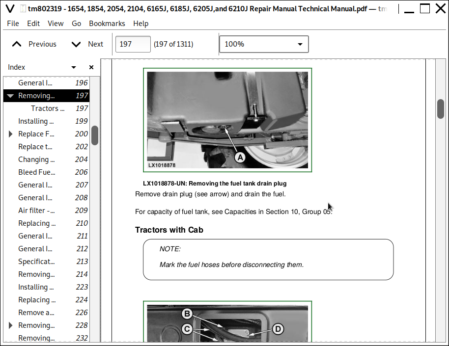
![]()