
John Deere Tractors 550, 554, 5055B, 600, 604, 650, 654, 700, 704 Service Technical Manual (TM701619)
Complete diagnosis & repair technical manual with electrical wiring diagrams for John Deere 2WD or MFWD China Tractors 550, 554, 5055B, 600, 604, 650, 654, 700,704, 550-1, 554-1, 600-1, 604-1, 650-1,654-1, 700-1 and 704-1, with workshop information to maintain, diagnose, repair, and service like professional mechanics.
John Deere Tractors 550, 554, 5055B, 600, 604, 650, 654, 700, 704 workshop operation test service repair manual includes:
* Numbered table of contents easy to use so that you can find the information you need fast.
* Detailed sub-steps expand on repair procedure information
* Numbered instructions guide you through every repair procedure step by step.
* Troubleshooting and electrical service procedures are combined with detailed wiring diagrams for ease of use.
* Notes, cautions and warnings throughout each chapter pinpoint critical information.
* Bold figure number help you quickly match illustrations with instructions.
* Detailed illustrations, drawings and photos guide you through every procedure.
* Enlarged inset helps you identify and examine parts in detail.
tm701619 - 550, 554, 5055B, 600, 604, 650, 654, 700,704, 550-1, 554-1, 600-1, 604-1, 650-1,654-1, 700-1 and 704-1 Tractors Technical Manual.pdf
tm701619 - 550, 554, 5055B, 600, 604, 650, 654, 700,704, 550-1, 554-1, 600-1, 604-1, 650-1,654-1, 700-1 and 704-1 Tractors Technical Manual.epub
Total Pages: 1,410 pages
File Format: PDF/EPUB/MOBI/AZW (PC/Mac/Android/Kindle/iPhone/iPad; bookmarked, ToC, Searchable, Printable)
Language: English
MAIN SECTIONS
Foreword
General Information
Safety
Specifications
Fuel and Lubricants
Serial Number Locations
Drain Oil and Water Before Servicing
Engine
Engine
Cooling System
Fuel and Air
Speed Control Linkage
Fuel System
Air Intake System
Electrical System
Battery, Starter and Alternator
Electrical System Components
Wiring Harness
Fuses And Relays
Wiring Diagram
Power Train
Towing
Component Removal
PTO
Clutch
Clutch Housing
Transaxle
Differential
Final Drives
MFWD Drop Gearbox
Front Axle-MFWD
Front Axle-2WD
Steering and Brakes
Steering Repair
Brake Repair
Air Brake
Hydraulics
Hydraulic Pump, Filter and Lines
Rockshaft
Drawbar
Miscellaneous
Hood and Shields
3-Point Hitch
Wheels
Front Support
Cab Operator Station
Removal and Installation of Components (CAB)
Removal and Installation of Components (OOS)
Seat
SPECIAL TOOLS (Dealer-Fabricated)
DEALER-FABRICATED TOOLS
Operational Checkout Procedures
Operational Checkout Procedures
Engine Operation Theory, Test and Adjust
Component Locations
Theory of Operation
Diagnose, Test, and Adjust
Fuel and Air System Operation Theory, Test, and Adjustment
Component Locations
Theory of Operation
Diagnose, Test, and Adjustments
Operational principles, test and adjustment of electrical system
Component locations
Operational principles
Diagnose, test and adjust
Wiring Diagram
Operational principles, test and adjustment of drive system
Component locations
Operational principles
Diagnose, test and adjust
Operational principles, test and adjustment of steering and braking devices
Component locations
Operational principles
Diagnose, test and adjust
Operational principles, test and adjustment of hydraulic system
Component locations
Theory of Operation
Diagnose, test and adjust
tm701619 - 550, 554, 5055B, 600, 604, 650, 654, 700,704, 550-1, 554-1, 600-1, 604-1, 650-1,654-1, 700-1 and 704-1 Tractors Technical Manual
Table of Contents
Foreword
Section 10: General Information
Group 05: Safety
Recognize Safety Information
Live With Safety
Understand Signal Words
Follow Safety Instructions
Prepare for Emergencies
Wear Protective Clothing
Protect Against Noise
Handle Fuel Safely—Avoid Fires
Avoid Static Electricity Risk When Refueling
Handle Starting Fluid Safely
Keep ROPS Installed Properly
Use Foldable ROPS and Seat Belt Properly
Stay Clear of Rotating Drivelines
Use Steps and Handholds Correctly
Use Seat Belt Properly
Operating the Tractor Safely
Limited Use in Forestry Operation
Operating the Loader Tractor Safely
Keep Riders Off Machine
Instructional Seat
Use Safety Lights and Devices
Use a Safety Chain
Transport Towed Equipment at Safe Speeds
Use Caution On Slopes and Uneven Terrain
Freeing a Mired Machine
Avoid Contact with Agricultural Chemicals
Handle Agricultural Chemicals Safely
Handling Batteries Safely
Avoid Heating Near Pressurized Fluid Lines
Remove Paint Before Welding or Heating
Handle Electronic Components and Brackets Safely
Practice Safe Maintenance
Avoid Hot Exhaust
Work In Ventilated Area
Support Machine Properly
Prevent Machine Runaway
Park Machine Safely
Transport Tractor Safely
Engine Coolant
Service Cooling System Safely
Service Accumulator Systems Safely
Service Tires Safely
Service Front-Wheel Drive Tractor Safely
Tightening Wheel Retaining Bolts/Nuts
Do Not Open High-Pressure Fuel System
Avoid High-Pressure Fluids
Dispose of Waste Properly
Work in Clean Area
Service Machines Safely
Illuminate Work Area Safely
Use Proper Lifting Equipment
Construct Dealer-Made Tools Safely
Use Proper Tools
Fire Prevention
In Case of Fire
Avoid Backover Accidents
Clean Exhaust Filter Safely
Solutions for Emergencies
Group 10: Specifications
Technical Specifications of 2WD Machine
Technical Specifications of 4WD Machine
Maximum Control Force
Minimum Turning Radius
PTO Shaft Properties
Traction Properties
Properties of Hydraulic Suspension System
Pouring Capacity (L/gal)
Metric Bolt and Screw Torque Values
Torque Values of Imperial Bolts and Screws
Hydraulic System Imperial Connector Torque
Hydraulic System Metric Connector Torque
Clean Air Filter
Check Hose Clamps
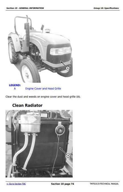
Clear Dust On Engine Cover and Hood Grille
Clean Radiator
Check Oil Level of Gearbox, Lifter and Front Drive Axle
Clean Battery
Check Neutral Start Circuit
Tractor Operation Check
Group 15: Fuel and Lubricants
Handle Fuel Safely—Avoid Fires
Handle Fluids Safely—Avoid Fires
Handling and Storing Diesel Fuel
Cold Weather Operation
Hot Weather Operation
Diesel Fuel
Lubricity of Diesel Fuel
Testing Diesel Fuel
Fill Fuel Tank
Alternative and Synthetic Lubricants
Lubricant Storage
Diesel Engine Break-In Oil
Diesel Engine Oil
Oil Filters
Heavy Duty Diesel Engine Coolant
Use Water As Coolant
Liquid Coolant Conditioner
Transmission and Hydraulic Oil
Use Correct Transmission/Hydraulic Filter Element
MFWD Front Axle Housing Oil
MFWD Wheel Hub Oil
Fill The Transmission With Oil
Check And Service Transmission Regularly
Grease (Specific Application)
Grease
Group 20: Serial Number Locations
Serial Number
Tractor Serial Number
Tractor Machine Serial Number - 13 Digits PIN
Engine Serial Number
Group 25: Drain Oil and Water Before Servicing
MFWD Model Front Axle Oil Drain
MFWD Model Drive Transfer Case Oil Drain
Steering Oil Tank Drain
Gearbox Oil Drain
Lifter Oil Drain
Oil Tank Diesel Drain
Drain Coolant
Engine Oil Drain
Section 20: Engine
Group 05: Engine
Essential or Recommended Tools
Specifications
Engine Maintenance
Remove and Install Engine
Group 10: Cooling System
Specifications
Engine Water Pump Repair
Remove, Install, and Adjust Fan Drive Belt
Remove, Inspect, and Install Radiator
Remove Thermostat
Install Thermostat
Section 30: Fuel and Air
Group 05: Speed Control Linkage
Specifications
Inspect and Repair Speed Control Linkage (OOS)
Inspect and Repair Speed Control Linkage (CAB)
Adjust Throttle Linkage
Adjust Foot Throttle Pedal Pressure (OOS)
Adjust Shut Down Cable
Adjust Hand Throttle Handle (OOS)
Adjust Throttle Lever Friction Nut (CAB)
Adjust Synchronization of Foot Throttle Pedal and Hand Throttle Handle (OOS)
Group 10: Fuel System
Specifications
Injection Pump, Nozzle, and Governor Repair
Fuel Tank Explosive View (OOS)
Fuel Tank Explosive View (CAB)
Remove and Install Fuel Tank (OOS)
Remove and Install Fuel Tank (CAB)
Replace Fuel Pump
Replace Sediment Bowl (OOS)
Replace Sediment Bowl Assembly (OOS)
Replace Fuel Filter and Engine Oil Filter
Bleed Fuel System
Group 15: Air Intake System
Specifications
Inspect and Repair Air Filter
Air Filter Maintenance
Inspect and Repair Muffler
Section 40: Electrical System
Group 05: Battery, Starter and Alternator
Prevent Damage to Electrical Systems
Prevent Battery Explosions
Handle Batteries Safely
Battery Replacement Specification
Charge Batteries
Connect Battery Cables
Remove and Install Battery
Remove and Install Engine
Group 10: Electrical System Components
Service Equipment and Tools
Replace Water Temperature Sensor
Replace Engine Oil Pressure Switch
Replace Engine Speed Sensor
Replace Fuel Level Sender (OOS)
Replace Fuel Level Sender (CAB)
Replace Key Switch (OOS)
Replace Key Switch (CAB)
Replace Hazard Warning Switch (OOS)
Replace High Low Beam Switch/Light Switch/Floodlight Switch/Turn Light Switch/Horn Switch (OOS)
Replace High Low Beam Switch/Rear Floodlight Switch/Wiper Switch (CAB)
Replace Hazard Warning Switch/Light Switch/Turn Light Switch (CAB)
Replace Horn Switch/Front Floodlight Switch (If Equipped) (CAB)
Replace Brake Lamp Switch (OOS)
Replace Brake Lamp Switch (CAB)
Replace Air Pressure Switch (If Equipped)
Replace Horn
Replace Flasher (OOS)
Replace Flasher (CAB)
Replace Trailer Connector (If Equipped)
Replace Neutral Start Switch (OOS)
Replace Neutral Start Switch (CAB)
Replace PTO Switch
Replace Wiper Motor
Replace Dome Lamp
Group 15: Wiring Harness
Wire Repair Pliers
Electrical Connector Handling
Remove Connector Body from Blade Terminals
Replace Connector
Install Contact
Wiring Harness (OOS)
Wiring Harness (CAB)
Group 20: Fuses And Relays
Locate Fuses
Fuse Specification and Function
Replace Starter Relay (OOS)
Replace Starter Relay (CAB)
Group 25: Wiring Diagram
Cable Color Codes
Electrical Schematic (OOS)
Electrical Schematic (CAB)
Section 50: Power Train
Group 00: Towing
Tow Tractor
Group 05: Component Removal
Essential or Recommended Tools
Other Material
Specifications
Transmission Separation
Transmission Component Identification
Transmission Drain Plug Locations
Remove and Install Rear Axle Assembly
Remove and Install Final Drive Assembly
Remove and Install Clutch
Remove, Inspect, and Install MFWD Drive Shaft
Remove and Install MFWD Drop Gearbox
Remove and Install Front Axle - MFWD
Remove and Install Front Axle - 2WD
Group 10: PTO
Essential or Recommended Tools
Service Equipment and Tools
Other Material
PTO-Exploded View
PTO Lever Assembly-Exploded View
Disassemble and inspect PTO assembly
Assemble PTO assembly
Group 15: Clutch
Essential or Recommended Tools
Service Equipment and Tools
Other Material
Specifications
Separate and Install Engine-to-Clutch Housing
Remove and Install Clutch Linkage (OOS Models)
Remove and Install Clutch Linkage (CAB Models)
Adjust Clutch Pedal and Linkage (OOS)
Adjust Clutch Pedal and Linkage (CAB)
Exploded View of Clutch
Disassemble and Inspect Clutch
Assemble Clutch
Group 20: Clutch Housing
Essential or Recommended Tools
Service Equipment and Tools
Other Material
Specifications
Remove and Disassemble Clutch Housing
Assemble Clutch Housing
Group 25: Transaxle
Essential or Recommended Tools
Service Equipment and Tools
Other Material
Specifications
Disassemble Transmission Main Housing
Disassemble Gear Case Upper Cover
Assemble Gear Case Upper Cover
Assemble and Install Transmission Main Housing
Group 30: Differential
Essential or Recommended Tools
Service Equipment and Tools
Other Material
Specifications
Remove Differential
Remove Differential (Creeper)
Disassemble Differential Lock
Disassemble Differential Kit
Assemble Differential Kit
Install Differential
Install Differential (Creeper)
Install Differential Lock
Group 35: Final Drives
Essential or Recommended Tools
Service Equipment and Tools
Other Material
Specifications
Final Drives-Exploded View
Remove and Install Final Drive
Disassemble, Inspect and Assemble Final Drive
Group 40: MFWD Drop Gearbox
Essential or Recommended Tools
Service Equipment and Tools
Other Material
Disassemble MFWD Drop Gearbox
Assemble MFWD Drop Gearbox
Group 45: Front Axle—MFWD
Essential or Recommended Tools
Service Equipment and Tools
Other Material
Specifications
Remove and Install Steering Rod Assembly - MFWD
Disassemble Front Rear Drive Assembly - MFWD
Assemble Front Rear Drive Assembly - MFWD
Disassemble Front Main Drive Assembly - MFWD
Assemble Front Main Drive Assembly - MFWD
Group 50: Front Axle—2WD
Essential or Recommended Tools
Service Equipment and Tools
Other Material
Specifications
Remove, Inspect, and Install Tie Rod Assembly - 2WD
Disassemble Front Axle Assembly - 2WD
Disassemble Front Hub
Assemble Front Hub
Assemble Front Axle Assembly - 2WD
Section 60: Steering and Brakes
Group 05: Steering Repair
Service Equipment and Tools
Specifications
Service Parts Kits
Remove and Install Steering Wheel
Remove and Install Steering Column
Disassemble Hydraulic Steering Oil Tank
Remove and Install Steering Valve
Disassemble and Inspect Steering Valve
Assemble Steering Valve
Remove and Install Steering Cylinder
Disassemble, Inspect and Assemble Steering Cylinder
Disassemble Constant Flow Pump
Check Toe-in (2WD)
Adjust Toe-in (2WD)
Check Toe-in (MFWD)
Adjust Toe-in (MFWD)
Group 10: Brake Repair
Service Equipment and Tools
Other Material
Specifications
Remove and Replace Brake Pedals and Linkage
Adjust Brake Linkage
Remove and Install Brakes
Disassemble Brakes (LH and RH)
Assemble Brakes (LH and RH)
Group 15: Air Brake
Remove and Install Brake Valve
Remove and Install Air Reservoir
Remove and Install Air Outlet Pipe Connector
Remove and Install Air Pipe
Air pump maintenance
Section 70: Hydraulics
Group 05: Hydraulic Pump, Filter and Lines
Remove and Install Hydraulic Pump (OOS)
Remove and Install Hydraulic Pump (CAB)
Remove and Install Hydraulic Oil Filter
Remove and Install Rockshaft Tubes
Group 10: Rockshaft
Specifications
Remove and Install Rockshaft Housing
Remove and Install Rockshaft Cover
Remove and Install Rockshaft Components-Truncation Lever Limit Plate Assembly
Remove and Install Rockshaft Components-Lift Arms and Rockshaft
Remove and Install Rockshaft Components-Control Linkages
Remove and Install Rockshaft Components-Cylinder and Distribution Assembly
Remove and Install Rockshaft Components-Disassemble Distribution
Remove and Install Rockshaft Components-Cylinder
Remove and Install Rockshaft Components-Dipstick
Group 15: Drawbar
Remove and Install Drawbar
Section 80: Miscellaneous
Group 05: Hood and Shields
Specifications
Engine Hood Explosive View (OOS)
Engine Hood Explosive View (CAB)
Remove Engine Hood (OOS)
Install Engine Hood (OOS)
Remove Engine Hood (CAB)
Install Engine Hood (CAB)
Remove and Install Air Cylinder
Remove and Install Engine Hood Lock
Remove and Install PTO Shield
Group 10: 3-Point Hitch
3-Point Hitch Exploded View
Adjust Center Link
Remove and Install Center Link
Adjust Adjustable Lift Link
Remove and Install Adjustable Lift Link
Remove and Install Draft Link
Adjust Stabilizer Chains
Remove and Install Stabilizer Chains
Remove and Install Sway Chain Bracket
Group 15: Wheels
Specifications
Remove and Install Front Wheels (2WD)
Remove and Install Front Wheels (4WD)
Remove and Install Rear Wheel
Rear Ballast
Group 20: Front Support
Specifications
Remove, Inspect and Install Front Support
Section 90: Cab Operator Station
Group 05: Removal and Installation of Components (CAB)
Service Equipment and Tools
Essential Tools
Specifications
Remove and Install Headliner
Remove and Install Upholstery
Remove and Install Front Windshield
Remove and Install Windshield Wiper
Remove and Install Rear Window
Remove and Install Rear Lower Window
Remove and Install Side Windows
Remove and Install Cab Door
Remove and Install Cab Outer Roof
Remove and Install Safety Exit Door
Remove and Install Door Lock
Remove Operator Cab
Install Operator Cab
Group 10: Removal and Installation of Components (OOS)
Essential or Recommended Tools
Service Equipment and Tools
Remove and Install ROPS
Remove and Install Frame
Remove and Install Cowl
Remove and Install Fender and Platform
Remove and Install Pedal
Group 15: Seat
Remove and Install Seat
Section 99: SPECIAL TOOLS (Dealer-Fabricated)
Group 05: DEALER-FABRICATED TOOLS
Special tool Q23-5 for installing bearing 305
Special tool Q23-6 for installing bushes
Special tool Q22-56 for installing oil seals
Special tool Q22-57 for installing bearings
Special tool Q22-105 for installing brake camshaft
Special tool Q22-3 for installing reverse gear composite bush
Special tool Q23-3 for installing bearing 6207
Special tool Q22-106 for installing bearing 30211 inner ring
Section 210: Operational Checkout Procedures
Group 05: Operational Checkout Procedures
Operational Checkout Procedure Information
Engine Oil Level and Condition Check
Coolant Level and Condition Check
Transmission Oil Check
Hydraulic Oil Check
Fan and Belt Check
Fuel System Check
Air Intake System Check
Electrical System Check
Hydraulic System Check
Indicator Lamps Check
Engine Start Check
Power Steering Check
Differential Lock Check
Mechanical Front Wheel Drive (MFWD) Check
Clutch Check
Transmission Shift Check
Range Lever Shift Check
Brake Check
Rockshaft Check
Miscellaneous Checks
Section 220: Engine Operation Theory, Test and Adjust
Group 05: Component Locations
Component Location Information
Engine External Components—Left-Hand Side
Engine External Components—Right-Hand Side
Group 10: Theory of Operation
Theory of Operation Information
Engine Cooling System Operation
Group 15: Diagnose, Test, and Adjust
Specifications
Cooling System Test
Adjust Throttle
Fan/Alternator Drive Belt Adjustment
Bleed Fuel System
Air Filter Plugged
Engine Not Starting or is Difficult to Start
Engine Does Not Develop Full Power
Engine Exhausts Black Smoke
Engine Exhausts Blue Smoke
Engine Exhausts White Smoke
Engine Oil Pressure is Abnormal
Engine Oil Level Rises
Abnormal Sound
Engine Coolant Temperature is High
Engine Oil Consumption is Too Much
Oscillating Seriously
Starter fault
Alternator Fault
Section 230: Fuel and Air System Operation Theory, Test, and Adjustment
Group 05: Component Locations
Component Location Information
Fuel System Components
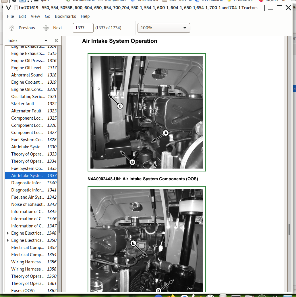
Air Intake System Components
Group 10: Theory of Operation
Theory of Operation Information
Fuel System Operation
Air Intake System Operation
Group 15: Diagnose, Test, and Adjustments
Diagnostic Information
Fuel and Air System Diagnose, Test, and Adjustments
Noise of Exhausts Iis Abnormal
Section 240: Operational principles, test and adjustment of electrical system
Group 05: Component locations
Information of Component Locations
Engine Electrical Components (OOS)
Engine Electrical Components (CAB)
Electrical Components of Dashboard and Main Control Panel (OOS)
Electrical Components of Dashboard and Main Control Panel (CAB)
Wiring Harness (OOS)
Wiring Harness (CAB)
Group 10: Operational principles
Theory of Operation Information
Fuses (OOS)
Fuses (CAB)
Relays
Starting System Operation (OOS)
Starting System Operation (CAB)
Battery Charging System Operation (OOS)
Battery Charging System Operation (CAB)
Lighting System Operation - Left/Right Turning Signal (OOS)
Lighting System Operation - Left/Right Turning Signal (CAB)
Lighting System Operation - High/Low Beam (OOS)
Lighting System Operation - High/Low Beam (CAB)
Lighting System Operation - Dashboard Light (OOS)
Lighting System Operation- Dashboard Light (CAB)
Lighting System Operation - Floodlight (OOS)
Lighting System Operation - Floodlight (CAB)
Lighting System Operation - Tail Lamp, Position Lamp and Brake Lamp (OOS)
Lighting System Operation - Tail Lamp, Position Lamp and Brake Lamp (CAB)
Lighting System Operation - Hazard Warning Light (OOS)
Lighting System Operation - Hazard Warning Light (CAB)
Dashboard System Operation - Engine Oil Pressure Indicator (OOS)
Dashboard System Operation- Engine Oil Pressure Indicator (CAB)
Dashboard System Operation - Air Pressure Indicator (OOS)
Dashboard System Operation - Air Pressure Indicator (CAB)
Dashboard System Operation - Tachometer (OOS)
Dashboard System Operation - Tachometer (CAB)
Dashboard System Operation - Fuel Gauge (OOS)
Dashboard System Operation - Fuel Gauge (CAB)
Dashboard System Operation - Water Temperature Gauge (OOS)
Dashboard System Operation - Water Temperature Gauge (CAB)
Horn Operation (OOS)
Horn Operation (CAB)
Dome Light Operation (CAB)
Wiper Operation (CAB)
Fan Operation (CAB)
Group 15: Diagnose, test and adjust
Diagnostic Information
Cable Color Table
Starting System Test Point - Normal Operation (OOS)
Starting System Test Point - Normal Operation (CAB)
Battery Charging System Test Point (OOS)
Battery Charging System Test Point (CAB)
Lighting System Test Points - Left/Right Turning Signal (OOS)
Lighting System Test Points - Left/Right Turning Signal (CAB)
Lighting System Test Points - High/Low Beam (OOS)
Lighting System Test Points - High/Low Beam (CAB)
Lighting System Test Points - Dashboard Light (OOS)
Lighting System Test Points - Dashboard Light (CAB)
Lighting System Test Points - Floodlight (OOS)
Lighting System Test Points - Floodlight (CAB)
Lighting System Test Points - Tail Lamp, Position Lamp and Brake Lamp (OOS)
Lighting System Test Points - Tail Lamp, Position Lamp and Brake Lamp (CAB)
Lighting System Test Points - Hazard Warning Light (OOS)
Lighting System Test Points - Hazard Warning Light (CAB)
Dashboard System Test Points - Engine Oil Pressure Indicator (OOS)
Dashboard System Test Points - Engine Oil Pressure Indicator (CAB)
Dashboard System Test Points - Air Pressure Indicator (OOS)
Dashboard System Test Points - Air Pressure Indicator (CAB)
Dashboard System Test Points - Tachometer (OOS)
Dashboard System Test Points - Tachometer (CAB)
Dashboard System Test Points - Fuel Gauge (OOS)
Dashboard System Test Points - Fuel Gauge (CAB)
Dashboard System Test Points - Water Temperature Gauge (OOS)
Dashboard System Test Points - Water Temperature Gauge (CAB)
Horn Test Points (OOS)
Horn Test Points (CAB)
Dome Light Test Points (CAB)
Wiper Test Points (CAB)
Fan Test Points (CAB)
Battery Voltage Test
Charging Battery
Key Switch Test
Fuse Test
Neutral Start Switch Test
Hazard Warning Switch Test (OOS)
High/Low Beam Switch Test (OOS)
Light Switch Test (OOS)
Floodlight Switch Test (OOS)
Turn Switch Test (OOS)
Horn Switch Test (OOS)
Wiper Switch Test (CAB)
Rear Floodlight Switch Test (CAB)
High/Low Beam Switch Test (CAB)
Turn Switch Test (CAB)
Light Switch Test (CAB)
Hazard Warning Switch Test (CAB)
Horn Switch Test (CAB)
Front Floodlight Switch Test (CAB)
Group 20: Wiring Diagram
Cable Color Codes
Electrical Schematic (OOS)
Electrical Schematic (CAB)
Section 250: Operational principles, test and adjustment of drive system
Group 05: Component locations
Information of component locations
Transmission system components
Clutch components
Gearbox components
Final drive components
Rear PTO components
Group 10: Operational principles
Information of operational principles
Operational principles of clutch
Operational principles of gearbox
Operational principles of final drive
Operational principles of rear PTO shaft
Operational principles of drive transfer case transmission
Operational principles of MFWD
Group 15: Diagnose, test and adjust
Diagnostic information
Isolate defective components
Clutch slippage
Clutch incomplete separation
Clutch engagement
Clutch non-separation
Clutch pedal non-return
Unstable or unsteady power transmission
Gearbox oil level low (serious oil leakage)
Bumping gear, difficult shifting or non-engagement
Gearbox failing to stay at gear position
PTO shaft noisy
Difficulty in PTO shaft engagement
PTO shaft failing to stay at engaged status
Differential being noisy
Section 260: Operational principles, test and adjustment of steering and braking devices
Group 05: Component locations
Information of component locations
Steering system components
Brake system components
Group 10: Operational principles
Information of operational principles
Operational principles of steering system
Operational principles of braking system
Group 15: Diagnose, test and adjust
Diagnostic information
Isolate defective components - steering system
Being difficult or failed to steer
Isolate defective components - brake
Steering cylinder leakage test
Check toe-in (2WD)
Adjust toe-in (2WD)
Check toe-in (MFWD)
Adjust toe-in (MFWD)
Brake pedal adjustment
Section 270: Operational principles, test and adjustment of hydraulic system
Group 05: Component locations
Information of component locations
Rockshaft Assembly
Hydraulic Pump
Tubes
Group 10: Theory of Operation
Theory of Operation Information
Hydraulic System Operation
Group 15: Diagnose, test and adjust
Diagnostic information
Preliminary Hydraulic System Inspection
Entire Hydraulic System Fails to Function/No Hydraulic Pump Output
Insufficient Pump Delivery
Excessive Pump Pressure
Excessive Pump Noise During Operation
Rockshaft Does Not Lift or Lifts Slowly
John Deere Tractors 550, 554, 5055B, 600, 604, 650, 654, 700, 704 Service Technical Manual (TM701619)
![]()