
John Deere Rotary Mower Conditioners Models 916, 926 and 936 Diagnosis and Tests Service Manual (TM1823)

John Deere Rotary Mower Conditioners Models 916, 926 and 936 Diagnosis and Tests Service Manual (TM1823)
tm1823 - 916, 926 and 936 rotary mower conditioners Technical Manual.PDF
Complete service manual for John Deere 916, 926 and 936 Rotary Mower-Conditioners, with all the workshop information to maintain, diagnose, repair, service & rebuild like professional mechanics.
John Deere Rotary Mower Conditioners Models 916, 926 and 936 workshop Technical Manual includes:
* Numbered table of contents easy to use so that you can find the information you need fast.
* Detailed sub-steps expand on repair procedure information
* Numbered instructions guide you through every repair procedure step by step.
* Notes, cautions and warnings throughout each chapter pinpoint critical information.
* Bold figure number help you quickly match illustrations with instructions.
* Detailed illustrations, drawings and photos guide you through every procedure.
* Enlarged inset helps you identify and examine parts in detail.
Total Pages: 616 pages
File Format: PDF (bookmarked, ToC, Searchable, Printable, high quality)
Language: English
MAIN SECTIONS
Foreword
Service Technician Response
General
Safety
Specifications
General Information
Lubricants
Power Train
General Information
Diagnosing Malfunctions
Driveline Repair
Main Drive Gear Case-916
Main Drive Gear Case-926/36
Slip Clutch
Belt Drive
Cutterbar Drive Gear Case
Cutting Components
General Information
Diagnosing Malfunctions
Cutterbar Assembly
Disks and Knives
Platform-916
General Information
Platform Repair
Platform-926/36
General Information
Platform Repair
Conditioner
General Information
Diagnosing Malfunctions
Roll Bearings and Arms
Rolls
Impeller
Carrier Frame and Tongue-916
General Information
Diagnosing Malfunctions
Carrier Frame
Tongue
Carrier Frame and Tongue-926/36
General Information
Diagnosing Malfunctions
Carrier Frame
Tongue
Hydraulics-916
General Information
Diagnosing Malfunctions
Lift Cylinder
Hydraulics-926/36
General Information
Diagnosing Malfunctions
Lift Cylinders
Tongue Positioner Cylinder (Optional)
Tilt Cylinder (Top Link) (Optional)
Miscellaneous
Wheels and Wheel Support Assembly
Connector Repair
Dealer Fabricated Tools
Dealer Fabricated Tools
tm1823 - 916, 926 and 936 rotary mower conditioners
Table of Contents
Foreword
Service Technician Response
Section 10: General
Group 05: Safety
Recognize Safety Information
Understand Signal Words
Follow Safety Instructions
Operate Mower-Conditioner Safely
Keep Riders Off Machine
Handle Fluids Safely-Avoid Fires
Prepare for Emergencies
Handle Chemical Products Safely
Avoid High-Pressure Fluids
Stay Clear of Rotating Drivelines
Avoid Injury From Thrown Objects
Use Safety Lights and Devices
Use a Safety Chain
Tow Loads Safely
Support Machine Properly
Fire Prevention
In Case of Fire
Wear Protective Clothing
Work in Clean Area
Service Machines Safely
Illuminate Work Area Safely
Replace Safety Signs
Use Proper Lifting Equipment
Remove Paint Before Welding or Heating
Avoid Heating Near Pressurized Fluid Lines
Service Tires Safely
Practice Safe Maintenance
Use Proper Tools
Construct Dealer-Made Tools Safely
Dispose of Waste Properly
Live With Safety
Group 10: Specifications
Mower-Conditioner Specifications (Specifications and design subject to change without notice.)-916
Mower-Conditioner Specifications (Specifications and design subject to change without notice.)-926
Mower-Conditioner Specifications (Specifications and design subject to change without notice.)-936
Metric Bolt and Cap Screw Torque Values
Unified Inch Bolt and Cap Screw Torque Values
Group 15: General Information
Machine Description-916
Machine Description-926/36
Record Product Identification Numbers
Record Mower-Conditioner Serial Number
Metric And Customary Design
Repair Components
Unauthorized Modifications
Care Of V-Belts
Tighten Bearing Locking Collar
Group 20: Lubricants
Grease
Cutterbar and Gear Case Oil
Alternative and Synthetic Lubricants
Mixing of Lubricants
Lubricant Storage
Perform Lubrication and Maintenance
Section 20: Power Train
Group 05: General Information
Power Train Operation-916
Power Train Operation-926/36
Group 10: Diagnosing Malfunctions
Diagnose Driveline Malfunctions
Group 15: Driveline Repair
Other Material
Service Parts Kits
Specifications
General Information
Remove and Install PTO Hookup
Repair PTO Hookup
Repair PTO Sliding Collar Disconnect
Replace Drive Shaft and Bearings-916
Replace Power-Cushion Drive Shaft and Bearings-926/36
Remove and Install Rear Driveline
Repair Rear Driveline
Repair Cutterbar U-Joint Coupler
Group 20: Main Drive Gear Case-916
Service Equipment And Tools
Other Material
Service Parts Kits
Specifications
Remove and Install Main Drive Gear Case
Disassemble Main Drive Gear Case
Inspect Gear Case Parts
Assemble Main Drive Gear Case
Group 21: Main Drive Gear Case-926/36
Service Equipment And Tools
Other Material
Service Parts Kits
Specifications
Remove and Install Main Drive Gear Case
Disassemble Main Drive Gear Case
Inspect Gear Case Parts
Assemble Main Drive Gear Case
Convert Main Drive Gear Case RPM (926 Only)
Group 25: Slip Clutch
Other Material
Specifications
Replace Slip Clutch Lining
Remove and Install Slip Clutch
Disassemble and Inspect Slip Clutch
Assemble Slip Clutch
Check Slip Clutch for Proper Operation
Adjust Slip Clutch
Group 30: Belt Drive
Specifications
Replace Cutterbar Drive Belt
Adjust Cutterbar Drive Belt Tension
Group 35: Cutterbar Drive Gear Case
Essential or Recommended Tools
Service Equipment and Tools
Other Material
Service Parts Kits
Specifications
Remove Cutterbar Drive Gear Case
Disassemble Cutterbar Drive Gear Case
Inspect Gear Case Parts
Assemble Cutterbar Drive Gear Case
Install Cutterbar Drive Gear Case
Install Breather Tube
Section 30: Cutting Components
Group 05: General Information
Cutterbar Description
Group 10: Diagnosing Malfunctions
Diagnose Cutterbar Malfunctions
Group 15: Cutterbar Assembly
Service Equipment and Tools
Other Material
Service Parts Kits
Specifications
Drain Oil From Cutterbar
Remove and Install Cutterbar
Remove and Install Individual Intermediate Module from Cutterbar
Checking Dented Module
Repairing a Dented Module
Disassemble and Assemble Cutterbar
Remove Idler Gear Bearing From Idler Gear
Remove and Install Left-Hand End Quill Assembly
Remove and Install Right-Hand End or Intermediate Quill Assemblies
Cutterbar Quill and Pinion Gear Timing Detail-Disks Rotate Towards Center
Cutterbar Quill and Pinion Gear Timing Detail-Alternating Disk Rotation
Disassemble and Assemble Quill Assembly
Replace Left-Hand End Disk Driver
Replace Intermediate Disk Drivers
Replace Right-Hand End Disk Driver
Group 20: Disks and Knives
Specifications
Remove Disks
Install and Synchronize Disks
Check Knives and Knife Bolts for Wear
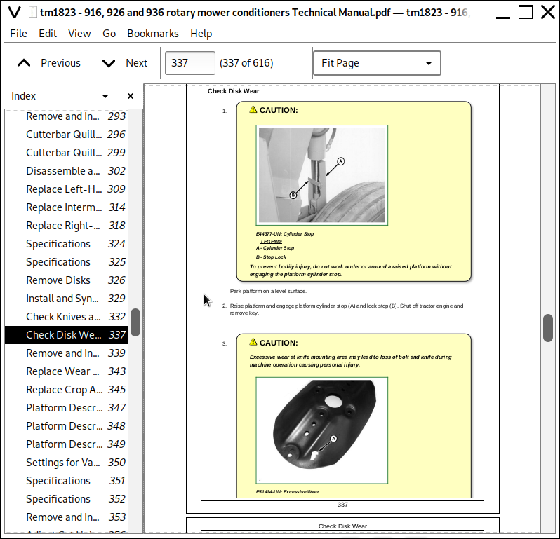
Check Disk Wear
Remove and Install Knives
Replace Wear Cap On Knife Bolt
Replace Crop Accelerator (If Equipped)
Section 40: Platform-916
Group 05: General Information
Platform Description
Settings for Various Crop Conditions
Group 10: Platform Repair
Specifications
Remove and Install Gauge Shoes
Adjust Cut Height
Adjust Cutterbar Angle
Adjust Platform Float
Adjust or Replace Float Spring Bolt Wear Pad
Remove and Install Platform
Section 41: Platform-926/36
Group 05: General Information
Platform Description
Settings for Various Crop Conditions
Group 10: Platform Repair
Specifications
Remove and Install Gauge Shoes
Adjust Cut Height-Turnbuckle Top Link
Adjusting Cut Height-Hydraulic Tilt Control
Adjusting Platform Float
Remove and Install Platform
Section 50: Conditioner
Group 05: General Information
Conditioner Description
Group 10: Diagnosing Malfunctions
Diagnose Roll Conditioner Malfunctions
Diagnose Impeller Conditioner Malfunctions
Group 15: Roll Bearings and Arms
Service Equipment And Tools
Specifications
Other Material
Remove Roll Bearings and Roll Arm-Left-Hand Side
Install Roll Bearings and Roll Arm-Left-Hand Side
Remove and Install Roll Bearings and Roll Arm-Right-Hand Side
Replace Roll Arm Bushing
Replace Idler Gear Bearings and Seals
Adjust Idler Gear Alignment
Group 20: Rolls
Specifications
Remove Rolls
Install Lower Roll
Install Upper Roll
Adjust Roll Alignment
Adjust Roll Timing
Adjust Roll Pressure
Adjust Roll Spacing
Group 25: Impeller
Specifications
Remove Impeller
Install Impeller
Change Impeller Rotor Speed
Section 60: Carrier Frame and Tongue-916
Group 05: General Information
Carrier Frame Description
Group 10: Diagnosing Malfunctions
Diagnosing Malfunctions
Group 15: Carrier Frame
Windrow Forming Shields
Adjust Windrow Width
Group 20: Tongue
Specifications
Other Material
Remove and Install Tongue
Repair Tongue Assembly
Section 61: Carrier Frame and Tongue-926/36
Group 05: General Information
Carrier Frame Description
Group 10: Diagnosing Malfunctions
Diagnosing Malfunctions
Group 15: Carrier Frame
Adjust Carrier Frame Height
Windrow Forming Shields
Adjust Windrow Width
Group 20: Tongue
Specifications
Other Material
Remove and Install Tongue-Front Half
Remove and Install Tongue-Rear Half
Repair Tongue (Front Half)
Section 70: Hydraulics-916
Group 05: General Information
Hydraulic Lift Cylinder (Platform Lift) Operation
Group 10: Diagnosing Malfunctions
Diagnose Lift Cylinder Malfunctions
Group 15: Lift Cylinder
Service Parts Kits
Specifications
Remove and Install Lift Cylinder
Disassemble and Inspect Lift Cylinder
Assemble Lift Cylinder
Section 71: Hydraulics-926/36
Group 05: General Information
Hydraulic Lift Cylinders Operation
Optional Tongue Positioner Cylinder Operation
Optional Hydraulic Tilt Cylinder Operation
Group 10: Diagnosing Malfunctions
Diagnose Lift Cylinder Malfunctions
Diagnose Tongue Positioner Cylinder Malfunctions
Diagnose Hydraulic Tilt Cylinder Malfunctions
Group 15: Lift Cylinders
Service Parts Kits
Specifications
Remove and Install Lift Cylinders
Disassemble and Inspect Master Lift Cylinder
Assemble Master Lift Cylinder
Disassemble and Inspect Slave Lift Cylinder
Assemble Slave Lift Cylinder
Install One-Way Orifice
Bleed Platform Lift Circuit
Phasing Lift Cylinders
Group 20: Tongue Positioner Cylinder (Optional)
Service Parts Kits
Specifications
Remove and Install Tongue Positioner Cylinder
Disassemble and Inspect Tongue Positioner Cylinder
Assemble Tongue Positioner Cylinder
Group 25: Tilt Cylinder (Top Link) (Optional)
Service Parts Kits
Specifications
Remove and Install Tilt Cylinder (Top Link)
Disassemble and Inspect Tilt Cylinder (Top Link)
Assemble Tilt Cylinder (Top Link)
Section 80: Miscellaneous
Group 05: Wheels and Wheel Support Assembly
Service Equipment And Tools
Specifications
Other Material
Remove and Install Wheel
Pack or Replace Wheel Bearings
Replace Lower Lift Arm (916)
Replace Lower Lift Arm Bushings (916)
Repair Wheel Support (926/36)
Group 10: Connector Repair
Essential or Recommended Tools
Other Material
Electrical Connector Handling
Use Contact Cleaner and Di-electric Grease
Replace WEATHER PACK WEATHER PACK is a trademark of Packard Electric. Connector
Install WEATHER PACK WEATHER PACK is a trademark of Packard Electric. Contact
Replace METRI-PACK (Push Type) Connectors
Harness Repair-Splice Connector
Lighting Enhancement Module
Tail and Warning Lights Wiring Diagram
Section 99: Dealer Fabricated Tools
Group 05: Dealer Fabricated Tools
DFEX1823A Backlash Measuring Strap
![]()