
John Deere Hay and Forage Round Balers Models 960, 990 Diagnosis and Tests Service Manual (TM300519)

Complete Diagnostics and Tests manual for John Deere 960 and 990 Hay and Forage Round Baler (Worldwide Edition), with all the shop information to maintain, diagnose, repair, and rebuild like professional mechanics.
John Deere Hay and Forage Round Balers Models 960 and 990 workshop Diagnosis Operation Tests manual includes:
* Numbered table of contents easy to use so that you can find the information you need fast.
* Detailed sub-steps expand on repair procedure information
* Numbered instructions guide you through every repair procedure step by step.
* Troubleshooting and electrical service procedures are combined with detailed wiring diagrams for ease of use.
* Notes, cautions and warnings throughout each chapter pinpoint critical information.
* Bold figure number help you quickly match illustrations with instructions.
* Detailed illustrations, drawings and photos guide you through every procedure.
* Enlarged inset helps you identify and examine parts in detail.
TM300519 - John Deere Hay and Forage Round Balers Models 960 and 990 Technical Manual (Operation and Tests).PDF
TM300519 - John Deere Hay and Forage Round Balers Models 960 and 990 Technical Manual (Operation and Tests).EPUB
Total Pages: 890 pages
File Format: PDF/EPUB/MOBI/AZW (PC/Mac/Android/Kindle/iPhone/iPad; bookmarked, ToC, Searchable, Printable)
Language: English
MAIN SECTIONS
Foreword
General Information
Safety Information
General References
Diagnostic Trouble Codes
Description
Diagnostic Trouble Code List
Troubleshooting
Troubleshooting
Electrical System
Schematic
Diagnostic Tests
Diagnostic Modes/ISOBUS Baler
Machine Setup - ISOBUS Baler
Connector and Component Information
Electrical Component Location
Component Information - A
Component Information - E
Component Information - H
Component Information - K
Component Information - M
Component Information - N
Component Information - R
Component Information - S
Component Information - V
Component Information - W
Component Information - Connectors (XB101 to XB199)
Component Information - Connectors (XB301 to XB399)
Component Information - Connectors (XB401 to XB499)
Component Information - Connectors (XB501 to XB599)
Component Information - Connectors (XB701 to XB799)
Component Information - Connectors (XB801 to XB899)
Component Information - Splices (XB901 to XB999)
Component Information - Connectors (Others)
Component Information - Y
Lubrication System - Operation and Tests
Theory of Operation
Lubrication System - Component Location
Air Brake System - Operation and Tests
Safety
Air Brake System - Description
Air Brake System - Tests
Hydraulic Brake System - Operation and Tests
Hydraulic Brake System - Description
Hydraulic Brake System - Tests
Hydraulic System - Operation and Tests
Safety
General Information
Bale Density and Gate Control - Description
Bale Density/Gate Control - Tests
Rotary Feeder Hydraulic System without Precutter Device - Description
Rotary Feeder Hydr. System w. Precutter Device 13 Knives-Description
Rotary Feeder Hydr. System w. Precutter Device 25 Knives-Description
Special Tools
Special Tools (Available as Spare Parts)
tm300519 - 960 and 990 Round Baler Diagnostics -: (Worldwide Edition)
Table of Contents
Foreword
Section 210: General Information
Group 05: Safety Information
Safety Information - Summary of References
Prevent Battery Explosions
Prepare for Emergencies
Prevent Acid Burns
Avoid High-Pressure Fluids
Support Machine Properly
Wear Protective Clothing
Service Machines Safely
Work in Clean Area
Remove Paint Before Welding or Heating
Avoid Heating Near Pressurized Fluid Lines
Illuminate Work Area Safely
Replace Safety Signs
Use Proper Lifting Equipment
Service Tires Safely
Practice Safe Maintenance
Use Proper Tools
Decommissioning — Proper Recycling and Disposal of Fluids and Components
Live With Safety
Safety Information - Air Brake System
Group 15: General References
General References - Summary of References
Unified Inch Bolt and Screw Torque Values
Metric Bolt and Screw Torque Values
Electrical Circuit Malfunctions
Open Circuit
Circuit Shorted to Ground
Shorted Circuit
How to Read a Functional Schematic
How to Read a Wiring and Harness Diagram
Symbols in System Diagrams
Component Identification Table
Section 211: Diagnostic Trouble Codes
Group 05: Description
Description - Summary of References
What is a DTC?
Group RBC: Diagnostic Trouble Code List
Diagnostic Trouble Code List - Summary of References
Warning Screens
Recent Problems
RBC 000168.16 - Battery Voltage too High
RBC 000168.18 - Battery Voltage too Low
RBC 001563.12 - Control Unit ID Error
RBC 003025.04 - Automatic Greasing System Relay Short to Ground
RBC 003025.05 - Automatic Greasing System Relay Open Load
RBC 003509.03 - Sensor Supply Voltage too High
RBC 003509.04 - Sensor Supply Voltage too Low
RBC 003755.15 - High Baler Drive Roll Speed
RBC 003755.16 - Baler Drive Roll Speed Above Proper Operation
RBC 003755.17 - Low Baler Drive Roll Speed
RBC 003755.18 - Baler Drive Roll Speed Below Proper Operation
RBC 003761.03 - Drop Floor Solenoid Valve Open Load or Shorted to Battery
RBC 003761.04 - Drop Floor Solenoid Valve Shorted to Ground
RBC 003762.03 - Precutter Knife Set 1 Solenoid Valve Open Load or Short to Battery
RBC 003762.04 - Precutter Knife Set 1 Solenoid Valve Short to Ground
RBC 003763.03 - Pickup Solenoid Valve Open Load or Short to Battery
RBC 003763.04 - Pickup Solenoid Valve Short to Ground
RBC 003764.07 - No Movement of the Actuator
RBC 003764.11 - Actuator Broken
RBC 003764.14 - Actuator Stalled
RBC 003766.12 - Twine Actuator Broken
RBC 003766.14 - Twine Actuator Stalled
RBC 003782.14 - Twine not cut
RBC 003774.11 - Gate Ajar. The Gate is in an Unknown Position
RBC 003776.07 - Bale Stuck in the Chamber
RBC 003776.14 - Bale Stuck on Ramp
RBC 003778.14 - Unexpected Movement of Knives 1 from Previous State
RBC 003779.05 - Unexpected Oversize Bale
RBC 003779.14 - Oversize Bale
RBC 003781.07 - Net not Feeding Properly
RBC 003781.08 - Net Stopped Feeding
RBC 003781.11 - Net Unexpectedly Feeding
RBC 003781.14 - Net not Cut after Tying
RBC 003782.07 - Twine not Feeding Properly
RBC 003782.11 - Twine Feeding Unexpectedly
RBC 20990.02 - Softkey Event Queue Full
RBC 20991.02 - Button Event Queue Full
RBC 20992.02 - Standard Signal Queue Full
RBC 20993.02 - Priority Signal Queue Full
RBC 20994.02 - No Process Timer Available
RBC 20995.02 - No Signal Timer Available
RBC 20996.02 - Unreachable Code
RBC 517003.04 - John Deere B-Wrap Sensor Supply Short to Ground
RBC 517003.05 - John Deere B-Wrap Sensor Supply Open Load
RBC 517004.04 - John Deere B-Wrap Sensor Short to Ground
RBC 517005.07 - John Deere B-Wrap Sensor do not Detect Metal Strip During Tying Cycle
RBC 517006.14 - End of John Deere B-Wrap Roll Detected
RBC 521075.03 - Precutter Knife Set 2 Solenoid Valve Open Load or Short to Battery
RBC 521075.04 - Precutter Knife Set 2 Solenoid Valve Short to Ground
RBC 521075.14 - Unexpected Movement of Knives 2 from Previous State
RBC 521078.14 - Unexpected Movement of Drop Floor from Previous State
RBC 521079.03 - Soft Core Solenoid Valve Open Load or Short to Battery
RBC 521079.04 - Soft Core Solenoid Valve Short to Ground
RBC 521083.03 - Right Bale Shape Sensor Shorted High
RBC 521083.04 - Right Bale Shape Sensor Shorted to Ground
RBC 521083.13 - Right Bale Shape Sensor not Calibrated
RBC 521083.16 - Right Bale Shape Sensor out of Range High
RBC 521083.18 - Right Bale Shape Sensor out of Range Low
RBC 521084.03 - Left Bale Shape Sensor Shorted High
RBC 521084.04 - Left Bale Shape Sensor Shorted to Ground
RBC 521084.13 - Left Bale Shape Sensor not Calibrated
RBC 521084.16 - Left Bale Shape Sensor out of Range High
RBC 521084.18 - Left Bale Shape Sensor out of Range Low
RBC 521086.03 - Bale Size Sensor Shorted High
RBC 521086.04 - Bale Size Sensor Shorted to Ground
RBC 521086.13 - Bale Size Sensor Not Calibrated
RBC 521086.14 - Bale Size Near Preset Size after Power Cycle
RBC 521086.16 - Bale Size Sensor out of Range High
RBC 521086.18 - Bale Size Sensor out of Range Low
RBC 521127.03 - Bale Density Sensor Short to Battery
RBC 521127.04 - Bale Density Sensor Short to Ground
RBC 522016.07 - Ramp Switch Problem
RBC 522022.02 - Calibration Mirror EEPROM, Checksum Failure on Last Power Down
RBC 522023.02 - Field Mirror EEPROM, Checksum Failure on Last Power Down
RBC 522024.02 - User Mirror EEPROM, Checksum Failure on Last Power Down
RBC 522025.02 - Automation Mirror EEPROM, Checksum Failure on Last Power Down
RBC 522026.02 - Dealer Mirror EEPROM, Checksum Failure on Last Power Down
RBC 522027.02 - Factory Mirror EEPROM, Checksum Failure on Last Power Down
RBC 522028.02 - Calibration EEPROM, Checksum Failure
RBC 522028.12 - Calibration EEPROM, Checksum Failure on Last Power Down
RBC 522029.02 - Field EEPROM, Checksum Failure
RBC 522029.12 - Field EEPROM, Checksum Failure on Last Power Down
RBC 522030.02 - User EEPROM, Checksum Failure
RBC 522030.12 - User EEPROM, Checksum Failure on Last Power Down
RBC 522031.02 - Automation EEPROM, Checksum Failure
RBC 522031.12 - Automation EEPROM, Checksum Failure on Last Power Down
RBC 522032.02 - Dealer EEPROM, Checksum Failure
RBC 522032.12 - Dealer EEPROM, Checksum Failure on Last Power Down
RBC 522033.02 - Factory EEPROM, Checksum Failure
RBC 522033.12 - Factory EEPROM, Checksum Failure on Last Power Down
RBC 523108.13 - Control Unit Output Problem on Net or Twine
RBC 523836.18 - Grease Reservoir Empty
RBC 523837.18 - Grease Reservoir Empty when System is Manually Activated
RBC 524063.03 - Actuator Short to Battery
RBC 524063.04 - Actuator Short to Ground
RBC 524063.05 - Actuator Open Load
RBC 524093.03 - Twine Actuator Short to Battery
RBC 524093.04 - Twine Actuator Short to Ground
RBC 524093.05 - Twine Actuator Open Load
Section 212: Troubleshooting
Group 10: Troubleshooting
Troubleshooting - Summary of References
Diagnose Hydraulic Functions
Net Tying Equipment Difficulties
Section 240: Electrical System
Group 30: Schematic
Schematic - Summary of References
Power Supply Schematic
CAN Bus System Schematic
Control Unit Schematic
Gate Control Schematic (Baler up to S.N. 150127)
Gate Control Schematic (Baler from S.N. 150128)
Net Tying Control Schematic (Baler up to S.N. 150127)
Net Tying Control Schematic (Baler from S.N. 150128)
Twine Tying Control Schematic
Pickup Lift Control Schematic
Precutter Knife Control Schematic
Drop Floor Control Schematic
Bale Control Schematic
Bale Discharging Ramp Control Schematic (Baler up to S.N. 150127)
Bale Discharging Ramp Control Schematic (Baler from S.N. 150128)
Automatic Greasing System Schematic (Baler up to S.N. 150127)
Automatic Greasing System Schematic (Baler from S.N. 150128)
Road Lighting System Schematic
B-Wrap System Schematic
Group 50: Diagnostic Tests
Diagnostic Tests - Summary of References
Check Fuse FB111 (Baler up to S.N. 150127)
Check Fuse FB111 (Baler from S.N. 150128)
Check Fuse FB112
Check Fuse FB115
Check Automatic Greasing System AB711
Check Net Actuator MB411
Check Twine Actuator MB421
Check Bale Diameter Potentiometer RB311
Check Left Bale Shape Potentiometer RB321
Check Right Bale Shape Potentiometer RB322
Check Bale Oversize Switch SB311
Check Left Gate Latch Sensor SB331
Check Density Pressure Sensor SB351
Check Left Gate Latch Sensor SB3310
Check Right Gate Latch Sensor SB3311
Check Right Gate Latch Sensor SB332
Check Bale Discharging Ramp Sensor SB341
Check Bale Discharging Ramp Sensor SB343
Check Baler Rotation Speed Sensor SB361
Check Baler Rotation Speed Sensor SB366
Check Net Feeding Sensor SB411
Check Net Feeding Sensor SB415
Check B-Wrap Sensor SB416
Check Left Twine Pulley 1 Sensor SB421
Check Right Twine Pulley 2 Sensor SB422
Check Drop Floor Sensor SB531
Check Sensor for Precutter Knife Set 1 SB551
Check Sensor for Precutter Knife Set 2 SB552
Check Proportional Density Solenoid Valve YB352
Check Pickup Lift Solenoid Valve YB511
Check Drop Floor Solenoid Valves YB531 and YB532
Check Solenoid Valve for Precutter Knife Set 1 YB551
Check Solenoid Valve for Precutter Knife Set 2 YB552
Group 50B: Diagnostic Modes/ISOBUS Baler
Diagnostic Modes - ISOBUS Baler - Summary of References
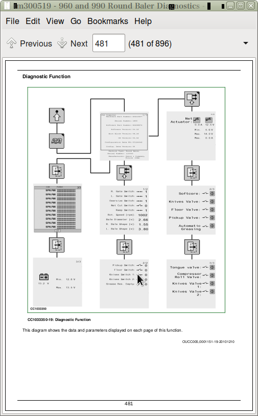
Diagnostic Function
Software Parameters
Recent Problem List
Test Tractor Battery Voltage
Test Net Actuator Electrical Consumption
Test Sensors and Switches
Test Electro-Hydraulic Components
Group 50C: Machine Setup - ISOBUS Baler
Machine Setup - ISOBUS Baler - Summary of References
Calibrate Bale Diameter Potentiometer RB311
Calibrate Bale Shape Potentiometers RB321 and RB322
Calibrate Net Tying Actuator MB411
Calibrate Twine Tying Actuator MB421
Enter Advanced Settings
Advanced Setting Function
Set Soft Core Device
Set Baler Rotation Speed Sensor Parameters
Set Linear Belt Speed
Set Third Bale Shape Potentiometer Device
Set Bale Discharging Ramp Sensor Device
Set Net Actuator Parameters
Set Pickup Sensor Device
Set Windrow Compressor Roll Device
Set Tongue Device
Section 249: Connector and Component Information
Group 35: Electrical Component Location
Electrical Component Location - Summary of References
Cab Electrical Component Location
Baler Electrical Component Location (Baler up to S.N. 150127)
Baler Electrical Component Location (Baler from S.N. 150128)
Group 40A: Component Information - Assemblies
Component Information - Assemblies - Summary of References
Component information - Assemblies - Specifications
AB144 - Electronic Control Unit
AB711 - Automatic Greasing Actuator
Group 40E: Component Information - Position Lights
Component Information - Position Lights - Summary of References
EB813 - Left Tail Light
EB814 - Right Tail Light
EB823 - Left Clearance Light
EB824 - Right Clearance Light
Group 40H: Component Information - Signal Lights
Component Information - Signal Lights - Summary of References
HB815 - Left Turn Light
HB816 - Right Turn Light
HB817 - Left Brake Light
HB818 - Right Brake Light
Group 40K: Component Information - Relays
Component Information - Relays - Summary of References
Component Information - Relays - Specifications
KB111 - Power Relay
Group 40M: Component Information - Motors
Component Information - Motors - Summary of References
MB411 - Net Actuator
MB421 - Twine Actuator
Group 40N: Component Information - CAN BUS Terminating Resistors
Component Information - CAN BUS Terminating Resistors - Summary of References
NB121 - CAN Bus Terminating Resistor
NB122 - CAN Bus Terminating Resistor
Group 40R: Component Information - Potentiometers
Component Information - Potentiometers - Summary of References
RB311 - Bale Diameter Potentiometer
RB321 - Left Bale Shape Potentiometer
RB322 - Right Bale Shape Potentiometer
Group 40S: Component Information - Switches
Component Information - Switches - Summary of References
Component Information - Switches - Specifications
SB311 - Bale Oversize Switch
SB331 - Left Gate Latch Sensor
SB332 - Right Gate Latch Sensor
SB341 - Bale Discharging Ramp Sensor
SB343 - Bale Discharging Ramp Sensor
SB351 - Density Pressure Sensor
SB361 - Baler Rotation Speed Sensor
SB366 - Baler Rotation Speed Sensor
SB411 - Net Feeding Sensor
SB415 - Net Feeding Sensor
SB416 - B-Wrap Sensor
SB421 - Left Twine Pulley 1 Sensor
SB422 - Right Twine Pulley 2 Sensor
SB531 - Drop Floor Sensor
SB551 - Sensor for Precutter Knife Set 1
SB552 - Sensor for Precutter Knife Set 2
SB3310 - Left Gate Latch Sensor
SB3311 - Right Gate Latch Sensor
Group 40V: Component Information - Semiconductors
Component Information - Semiconductors - Summary of References
Component Information - Semiconductors - Specifications
VB351 - Proportional Density Diode
Group 40W: Component Information - Wiring Harnesses
Component Information - Wiring Harnesses - Summary of References
WB1 - Main Wiring Harness (Baler up to S.N. 150127)
WB1 - Main Wiring Harness (Baler from S.N. 150128 up to S.N. 160386)
WB1 - Main Wiring Harness (Baler from S.N. 160387 up to S.N. 16xxxx)
WB1 - Main Wiring Harness (Baler from S.N. 16xxxx)
WB2 - Precutter Wiring Harness
WB3 - RotoFlow Wiring Harness
WB4 - Proportional Density Wiring Harness
WB5 - Automatic Greasing Wiring Harness
WB9 - Virtual Terminal Cab Wiring Harness
WB22 - B-Wrap Wiring Harness
WB23 - B-Wrap Jumper Wiring Harness
WB24 - B-Wrap Wiring Harness Extension
Group 40X1: Component Information - Connectors (XB101 to XB199)
Component Information - Connectors (XB101 to XB199) - Summary of References
XB111M - 3-terminal Plug for Power Supply
XB112F - 5-terminal Plug for Power Relay
XB112M - 5-terminal Plug for Power Relay
XB121F - 6-terminal Plug for CAN BUS Terminating Resistor
XB121M - 6-terminal Plug for CAN BUS Terminating Resistor
XB122F - 6-terminal Plug for CAN BUS Terminating Resistor
XB122M - 6-terminal Plug for CAN BUS Terminating Resistor
XB123M - Diagnostic Plug
XB134F - 26-terminal Plug for Monitor
XB1441F - 32-terminal Plug 1 for Control Unit
XB1441M - 32-terminal Plug 1 for Control Unit
XB1442F - 48-terminal Plug 2 for Control Unit
XB1442M - 48-terminal Plug 2 for Control Unit
XB1443F - 32-terminal Plug 3 for Control Unit
XB1443M - 32-terminal Plug 3 for Control Unit
Group 40X3: Component Information - Connectors (XB301 to XB399)
Component Information - Connectors (XB301 to XB399) - Summary of References
XB311F - 3-terminal Plug for Bale Diameter Potentiometer
XB311M - 3-terminal Plug for Bale Diameter Potentiometer
XB312F - 2-terminal Plug for Bale Oversize Switch
XB312M - 2-terminal Plug for Bale Oversize Switch
XB321F - 3-terminal Plug for Left Bale Shape Potentiometer
XB321M - 3-terminal Plug for Left Bale Shape Potentiometer
XB322F - 3-terminal Plug for Right Bale Shape Potentiometer
XB322M - 3-terminal Plug for Right Bale Shape Potentiometer
XB331F - 4-terminal Plug for Left Gate Latch Sensor
XB331M - 4-terminal Plug for Left Gate Latch Sensor
XB332F - 4-terminal Plug for Right Gate Latch Sensor
XB332M - 4-terminal Plug for Right Gate Latch Sensor
XB334F - 3-terminal Plug for Left Gate Latch Sensor
XB334M - 3-terminal Plug for Left Gate Latch Sensor
XB341F - 4-terminal Plug for Bale Discharging Ramp Sensor
XB341M - 4-terminal Plug for Bale Discharging Ramp Sensor
XB344F - 3-terminal Plug for Bale Discharging Ramp Sensor
XB344M - 3-terminal Plug for Bale Discharging Ramp Sensor
XB351F - 2-terminal Plug for Proportional Density
XB351MB - 2-terminal Plug for Proportional Density Wiring Harness
XB352F - 2-terminal Plug for Proportional Density Solenoid
XB352M - 2-terminal Plug for Proportional Density Solenoid
XB354F - 3-Terminal Plug for Pressure Sensor
XB354M - 3-Terminal Plug for Pressure Sensor
XB361F - 4-terminal Plug for Baler Rotation Speed Sensor
XB361M - 4-terminal Plug for Baler Rotation Speed Sensor
XB366F - 3-terminal Plug for Baler Rotation Speed Sensor
XB366M - 3-terminal Plug for Baler Rotation Speed Sensor
XB3312F - 3-terminal Plug for Right Gate Latch Sensor
XB3312M - 3-terminal Plug for Right Gate Latch Sensor
Group 40X4: Component Information - Connectors (XB401 to XB499)
Component Information - Connectors (XB401 to XB499) - Summary of References
XB411F - 2-terminal Plug for Net Actuator
XB411M - 2-terminal Plug for Net Actuator
XB412F - 4-terminal Plug for Net Feeding Sensor
XB412M - 4-terminal Plug for Net Feeding Sensor
XB416F - 3-terminal Plug for Net Feeding Sensor
XB416M - 3-terminal Plug for Net Feeding Sensor
XB418F - 2-terminal Plug for B-Wrap Wiring Harness
XB418M - 2-terminal Plug for B-Wrap Wiring Harness
XB4110F - 3-terminal Plug for B-Wrap Sensor
XB4110M - 3-terminal Plug for B-Wrap Sensor
XB4111F - 2-terminal Plug for B-Wrap Jumper Wiring Harness
XB4111M - 2-terminal Plug for B-Wrap Jumper Wiring Harness
XB422F - 2-Terminal Plug for Left Twine Pulley 1 Sensor
XB422M - 2-Terminal Plug for Left Twine Pulley 1 Sensor
XB423F - 2-Terminal Plug for Right Twine Pulley 2 Sensor
XB423FA - 2-Terminal Plug for Right Twine Pulley 2 Sensor
XB423M - 2-Terminal Plug for Right Twine Pulley 2 Sensor
XB423MA - 2-Terminal Plug for Right Twine Pulley 2 Sensor
XB424F - 2-Terminal Plug for Twine Actuator
XB424M - 2-Terminal Plug for Twine Actuator
Group 40X5: Component Information - Connectors (XB501 to XB599)
Component Information - Connectors (XB501 to XB599) - Summary of References
XB501FA - 12-terminal Plug for Precutter Wiring Harness
XB501FB - 12-Terminal Plug for RotoFlow Wiring Harness
XB501M - 12-terminal Plug for Pickup Wiring Harness
XB514FA - 2-terminal Plug for Pickup Lift Solenoid
XB514FB - 2-Terminal Plug for Pickup Lift Solenoid
XB514M - 2-Terminal Plug for Pickup Lift Solenoid
XB531FA - 4-terminal Plug for Drop Floor Sensor
XB531FB - 4-Terminal Plug for Drop Floor Sensor
XB531M - 4-Terminal Plug for Drop Floor Sensor
XB532FA - 2-terminal Plug for Drop Floor Solenoid 1
XB532FB - 2-Terminal Plug for Drop Floor Solenoid 1
XB532M - 2-Terminal Plug for Drop Floor Solenoid 1
XB533FA - 2-terminal Plug for Drop Floor Solenoid 2
XB533FB - 2-Terminal Plug for Drop Floor Solenoid 2
XB533M - 2-Terminal Plug for Drop Floor Solenoid 2
XB551F - 4-Terminal Plug for Sensor for Precutter Knife Set 1
XB551M - 4-terminal Plug for Sensor for Precutter Knife Set 1
XB552F - 2-Terminal Plug for Solenoid for Precutter Knife Set 1
XB552M - 2-terminal Plug for Solenoid for Precutter Knife Set 1
XB553F - 4-terminal Plug for Sensor for Precutter Knife Set 2
XB553M - 4-terminal Plug for Sensor for Precutter Knife Set 2
XB555F - 2-terminal Plug for Solenoid for Precutter Knife Set 2
XB555M - 2-terminal Plug for Solenoid for Precutter Knife Set 2
Group 40X7: Component Information - Connectors (XB701 to XB799)
Component Information - Connectors (XB701 to XB799) - Summary of References
XB711F - 4-terminal Plug for Automatic Greasing Wiring Harness
XB711M - 4-terminal Plug for Automatic Greasing Wiring Harness
XB712F - 4-terminal Plug for Automatic Greasing Actuator
XB712M - 4-terminal Plug for Automatic Greasing Actuator
Group 40X8: Component Information - Connectors (XB801 to XB899)
Component Information - Connectors (XB801 to XB899) - Summary of References
XB811F - 5-terminal Plug for Left Rear Lights
XB811M - 5-terminal Plug for Left Rear Lights
XB812F - 5-terminal Plug for Right Rear Lights
XB812M - 5-terminal Plug for Right Rear Lights
XB821F - 2-terminal Plug for Left Clearance Light
XB821M - 2-terminal Plug for Left Clearance Light
XB822F - 2-terminal Plug for Right Clearance Light
XB822M - 2-terminal Plug for Right Clearance Light
XB841M - 2-terminal Plug for Left Door Light Wiring Harness
XB842M - 2-terminal Plug for Right Door Light Wiring Harness
Group 40X9: Component Information - Splices (XB901 to XB999)
Component Information - Splices (XB901 to XB999) - Summary of References
XB901 - Splice
XB902 - Splice
XB903 - Splice
XB904 - Splice
XB905 - Splice
XB906 - Splice
XB907 - Splice
XB908 - Splice
XB909 - Splice
XB910 - Splice
XB911 - Splice
XB912 - Splice
XB913 - Splice
XB914 - Splice
XB915 - Splice
XB916 - Splice
XB917 - Splice
XB918 - Splice
XB919 - Splice
XB920 - Splice
XB922 - Splice
XB923 - Splice
XB924 - Splice
XB925 - Splice
XB926 - Splice
XB927 - Splice
XB928 - Splice
XB929 - Splice
XB950 - Splice
XB951 - Splice
Group 40XO: Component Information - Connectors (Others)
Component Information - Connectors (Others) - Summary of References
XIBC11783F - Implement Plug
XIBC11783M - Implement Plug
XTLC1724 - 7-terminal Plug for Lighting Electric Outlet
Group 40Y: Component Information - Solenoids
Component information - Solenoids - Summary of References
Component information - Solenoids - Specifications
YB352 - Proportional Density Solenoid Valve
YB511 - Pickup Lift Solenoid Valve
YB531 - Drop Floor Solenoid Valve 1
YB532 - Drop Floor Solenoid Valve 2
YB551 - Solenoid Valve for Precutter Knife Set 1
YB552 - Solenoid Valve for Precutter Knife Set 2
Section 250: Lubrication System - Operation and Tests
Group 05: Theory of Operation
Theory of Operation - Summary of References
Automatic Lubrication System
Multiluber Chain Oil Type
Lubrication System Pump
Group 10: Lubrication System - Component Location
Lubrication System - Component Location - Summary of References
Lubrication System - Component Location
Section 260A: Air Brake System - Operation and Tests
Group 05: Safety
Air Brake System - Operation and Tests - Safety - Summary of References
Working on the Air Brake System
Group 10: Air Brake System - Description
Air Brake System - Description - Summary of References
Description and Diagram (Baler with Air Brake System)
Group 15: Air Brake System - Tests
Air Brake System - Tests - Summary of References
Air Brake System - Tests - Specifications
Operational Check
Check for Leaks at Brake Circuit
Air Brake System - Tests - Check the Braking Pressure
Check Pilot Line Pressure
Section 260B: Hydraulic Brake System - Operation and Tests
Group 10: Hydraulic Brake System - Description
Hydraulic Brake System - Description - Summary of References
Description and Diagram (Baler with Hydraulic Brake System)
Group 15: Hydraulic Brake System - Tests
Hydraulic Brake System - Tests - Summary of References
Hydraulic Brake System - Tests - Check the Braking Pressure
Section 270: Hydraulic System - Operation and Tests
Group 05: Safety
Hydraulic System - Operation and Tests - Safety - Summary of References
Recommendations
Group 10: General Information
General Information - Summary of References
Hydraulic Symbols (As Defined by ISO 1219)
Group 20: Bale Density and Gate Control - Description
Bale Density and Gate Control - Description - Summary of References
Bale Density and Gate Control - Theory of Operation
Description and Diagram - Gate Control
Description and Diagram - Bale Density Control with Proportional Density Valve
Group 22: Bale Density/Gate Control - Tests
Bale Density and Gate Control - Tests - Summary of References
Bale Density and Gate Control - Tests - Specifications
Check Bale Density Hydraulic System
Check Gate Operation Hydraulic System
Check Bale Density Gauge
Check Density Hydraulic Circuit Pressure
Check Tension Cylinder for Leakage
Check Gate Cylinder for Leakage
Check Gate Lock Valve for Leakage
Check Density Hydraulic Circuit for Leakage
Check Accumulator Nitrogen Precharge
Group 35: Rotary Feeder Hydraulic System without Precutter Device - Description
Rotary Feeder Hydraulic System without Precutter Device - Description - Summary of References
Rotary Feeder Hydraulic System without Precutter Device - Description and Diagram
Group 40: Rotary Feeder Hydraulic System with 13 Knife Precutter Device - Description
Rotary Feeder Hydraulic System with 13 Knife Precutter Device - Description - Summary of References
Rotary Feeder Hydraulic System with 13 Knife Precutter Device - Description and Diagram
Group 45: Rotary Feeder Hydraulic System with 25 Knife Precutter Device - Description
Rotary Feeder Hydraulic System with 25 Knife Precutter Device - Description - Summary of References
Rotary Feeder Hydraulic System with 25 Knife Precutter Device - Description and Diagram
Section 399: Special Tools
Group 10: Special Tools (Available as Spare Parts)
Special Tools (Available as Spare Parts) - Summary of References
D01019AA - Hydraulic Hand-Operated Pump
FKM10474 - Fill and Check Device for Accumulators
JT05791 - Digital Multimeter
JT07115 - Pressure Test Kit
KJD10194 - Pressure Test Kit
John Deere Hay and Forage Round Balers Models 960, 990 Diagnosis and Tests Service Manual (TM300519)
![]()