
John Deere Self-Propelled Forage Harvesters Models 7200, 7300, 7400, 7500, 7700, 7800, 7900 Diagnosis & Test Service Manual (TM4670)
Complete Diagnostics Service Manual with Electrical Wiring Diagrams for John Deere 7200, 7300, 7400, 7500, 7700, 7800, 7900 Forage Harvesters (Worldwide Edition), with workshop information to maintain, diagnose, and service like professional mechanics.
John Deere Self-Propelled Forage Harvesters Models 7200, 7300, 7400, 7500, 7700, 7800, 7900 workshop Diagnosis & Tests service manual includes:
* Numbered table of contents easy to use so that you can find the information you need fast.
* Detailed sub-steps expand on repair procedure information
* Numbered instructions guide you through every repair procedure step by step.
* Troubleshooting and electrical service procedures are combined with detailed wiring diagrams for ease of use.
* Notes, cautions and warnings throughout each chapter pinpoint critical information.
* Bold figure number help you quickly match illustrations with instructions.
* Detailed illustrations, drawings and photos guide you through every procedure.
* Enlarged inset helps you identify and examine parts in detail.
TM4670 - John Deere Self-Propelled Forage Harvesters Models 7200, 7300, 7400, 7500, 7700, 7800, 7900 Technical Manual (Diagnosis & Test).PDF
TM4670 - John Deere Self-Propelled Forage Harvesters Models 7200, 7300, 7400, 7500, 7700, 7800, 7900 Technical Manual (Diagnosis & Test).EPUB
Total Pages: 5,413 pages
File Format: PDF/EPUB/MOBI/AZW (PC/Mac/Android/Kindle/iPhone/iPad; bookmarked, ToC, Searchable, Printable)
Language: English
MAIN SECTIONS
Diagnostic Trouble Codes
AMS Diagnostic Trouble Codes
ARC Diagnostic Trouble Codes
ECU Diagnostic Trouble Codes (6125 JD Control Unit Level 9)
ECU Diagnostic Trouble Codes (6125 JD Control Unit Level 6)
ECU Diagnostic Trouble Codes (Cummins Engine)
JDL Diagnostic Trouble Codes
OCP Diagnostic Trouble Codes
PTP Diagnostic Trouble Codes
RCP Diagnostic Trouble Codes
RDC Diagnostic Trouble Codes
RGC Diagnostic Trouble Codes
SIG Diagnostic Trouble Codes
SPF Diagnostic Trouble Codes
Observable Symptoms
System Diagnostics
Engine
Fuel, Air Intake and Cooling Systems
Electrical System (up to Serial No. 508099)
Electrical System
Power Distribution
Lighting System
Sockets
Wipers
Outside Mirrors
Ether Starting Aid
Horn
Engine Start
Air-Conditioning System
Warning Devices and Monitors
Area Counter Functions
Electronically Controlled Lighting Functions
Cutterhead Control Functions
Engine Cooling Functions
Engine Speed Control Functions
Feed Roll Control Functions
Header Control Functions
Kernel Processor Functions
Knife Sharpening Functions
Electronic Power Control Functions
Lubrication Control Functions
Metal Detector Functions
Drive Train Control Functions
Row Guidance Functions
Stationary Knife Adjust Function
Spout Control Functions
Trailer Functions
System Interlock Functions
On-Board Diagnostic Functions
CAN Bus System Functions
GreenStar Display/Moisture Sensor
AutoTrac
Functional Schematics – Sections 1 to 41
Wiring and Harness Diagrams, Connectors and Components
Wiring and Harness Diagrams (Splices)
Location of Wiring Harnesses
Control Units
Operation and General Information on Diagnostics
Test Equipment
CAN Bus System
GreenStar Control Unit (AMS)
Armrest Control Unit (ARC)
Engine Control Unit (ECU)
JDLink Control Unit (JDL)
Overhead Control Panel Control Unit (OCP)
ProDrive Control Unit (PTP)
Cornerpost Control Unit (RCP)
Rear Wheel Drive Control Unit (RDC)
Row Guidance I Control Unit (RGC I)
Row Guidance II Control Unit (RGC II)
Metal Detector Control Unit (SIG)
SPFH Main Control Unit (SPF)
AutoTrac Control Unit (SSU)
Power Train with 3-Speed Transmission
Power Train, ProDrive Transmission and Four-Wheel Drive
Brakes, Steering, Rear Axle
Brakes, Steering, Row Guidance II, Rear Axle for Machines from Serial Number 508100
Hydraulic System
Hydraulic Circuit Diagrams
Hydraulic System (Machines with ProDrive Transmission)
Hydraulic Circuit Diagrams
Operators`s Cab
Special Tools
IVLOC Transmission
tm4670 - 7200, 7300, 7400,7500, 7700 and 7800 Self-Propelled Forage HarvestersOperation and Tests
Table of Contents
Foreword
Version Date
Section 210: Safety and General Information
Group 05: Safety Information
Recognize Safety Information
”Important” Information
“Note” - Information
Prevent Machine Runaway
Handle Fluids Safely—Avoid Fires
Prevent Battery Explosions
Prepare for Emergencies
Prevent Acid Burns
Avoid High-Pressure Fluids
Service Cooling System Safely
Remove Paint Before Welding or Heating
Avoid Heating Near Pressurized Fluid Lines
Work In Ventilated Area
Wear Protective Clothing
Practice Safe Maintenance
Park Machine Safely
Use Proper Lifting Equipment
Construct Dealer-Made Tools Safely
Support Machine Properly
Work in Clean Area
Illuminate Work Area Safely
Service Machines Safely
Use Proper Tools
Service Tires Safely
Parking and Leaving the Forage Harvester
Avoid Eye Contact With Radar
Keep ROPS Installed Properly
Replace Safety Signs
Dispose of Waste Properly
Live With Safety
Safety Measures on Electronic Control Units
Group 15: General Information
Reference 210-15-001, General References - Summary
Reference 210-15-005, Abbreviations
Reference 210-15-010, Unified Inch Bolt and Cap Screw Torque Values
Reference 210-15-015, Metric Bolt and Cap Screw Torque Values
Reference 210-15-020, Hydraulic System Inch Fitting Torques
Reference 210-15-025, Hydraulic System Metric Fitting Torques
Reference 210-15-030, Serial Numbers
Forage Harvester Type Plate for Europe (Product Identification)
Forage Harvester Type Plate for North America (Product Identification)
Product Identification Number (Europe)
Product Identification Number (North America)
Engine Serial Number — Engine Type 6081
Engine Serial Number — Engine Type 6125
Engine Serial Number — Cummins
Operator's Cab Serial Number
Four Wheel Drive Motor Serial Number
Kernel Processor Serial Number
Power Chute Serial Number
Three-Speed Transmission Serial Number
Final Drive Serial Number
Angled Drive (Main Gearcase) Serial Number
Length-of-Cut Transmission Serial Number
IV Length-of-Cut Transmission Serial Number
IV Length-of-Cut Transmission Hydrostatic Pump Serial Number
IV Length-of-Cut Transmission Motor Serial Number
Main Drive Hydrostatic Pump Serial Number
Main Drive Motor Serial Number (Harvesters without Four Wheel Drive)
Rear Axle Serial Number
Reference 210-15-035, Dimensions
Reference 210-15-040, Specifications
Reference 210-15-045, Drive Diagram
Reference 210-15-060, Component Identification Table
Reference 210-15-065, How to Read a Functional Schematic
Reference 210-15-070, How to Read a Wiring and Harness Diagram
Reference 210-15-075, Schematic - Wiring and Harness Symbols
Schematic, Wiring and Harness Symbols
Schematic, Wiring and Harness Symbols
Schematic, Wiring and Harness Symbols
Reference 210-15-080, Visual Check of the Electrical System
Reference 210-15-085, Electrical Circuit Malfunctions
Reference 210-15-090, Seven Step Electrical Test Procedure
Reference 210-15-095, Hydraulic System — Circuit Symbols
Section 211: Diagnostic Trouble Codes
Group AMS: AMS Diagnostic Trouble Codes
Password
11.100 - Wrong Display Version
11.102 - No Connection to GreenStar Display
11.104 - Unexpected GreenStar Display Boot-Up
11.110 - RUN Page Layout
11.111 - Save Changes
11.112 - Restore Profile Defaults
11.113 - Save RUN Page Settings
11.114 - Layout Changes Not Saved
11.150 - Communication Error
11.152 - Communication Error
11.190 - Wrong Software Version
11.200 - CAN Bus Communication Error
11.202 - CAN Bus Communication Error
11.250 - Shorted Circuit
11.252 - System Malfunction
11.260 - Output Overload
11.261 - Job Computer Warning
11.300 - Feed Roll Speed min
11.301 - Feeding Speed max
11.302 - Feed Roll Height min
11.303 - Feed Roll Height max
11.304 - Moisture Level min
11.305 - Moisture Level max
11.306 - Feed Roll Height Sensor Defective
11.307 - Ref. Voltage Switched Off
11.310 - Start of External Reference?
11.311 - Place White Reference Tool
11.312 - Place Black Reference Tool
11.313 - 2700 Hours Exceeded
11.314 - 3000 Hours Exceeded
11.315 - Serial Number Invalid
11.316 - Software Version Invalid
11.317 - Internal Reference Fault
11.318 - External Reference Fault
11.319 - Internal Reference Stuck
11.321 - Download Completed
11.322 - Download not Complete
11.323 - Spectrum Invalid
11.324 - Sensor Startup
11.325 - Lamp Defective
11.326 - Memory Occupied
11.327 - Invalid Model
11.328 - Sensor Temperature
11.329 - Communication Diode Array
11.330 - Window Status
11.331 - No Calibration for NIR
11.333 - Reset Lamp Hours
11.334 - NIR Software Failure
11.335 - Ratio of Spectra too Low
11.500 - Transport
11.501 - RCP Communication Error
11.502 - SPFH Main Control Unit, Communication Error
11.503 - Metal Detect Com Error
11.504 - Armrest Control Unit, Communication Error
11.505 - Engine Control Unit, Communication Error
11.506 - No OBD Access
11.700 - No Setup During Calibration
11.701 - Calibration Running
11.702 - Material Flow too Low
11.703 - Totals are Different
11.704 - Calibrate?
11.900 - Clearing Custom Farm
11.901 - Clearing Custom Field
11.902 - Clear Field
11.903 - Clear Crop
11.904 - Clear Load
11.905 - Clear All Fields, Crops And Loads
11.906 - Clear All Fields
11.907 - Clear All Crops
11.908 - Clear All Loads
11.909 - Max Number of Fields
11.910 - Start new Load
11.911 - Max Number of Loads
20 - Implement Disconnected
21 - Display Conflict
30 - Too Many Devices on CAN Bus
31 - Display Overload
33 - Memory Error
110 - CAN Bus Problem
112 - Display Conflict, Run Page Configuration
Group ARC: ARC Diagnostic Trouble Codes
ARC 158.00 - Battery Voltage High
ARC 158.01 - Battery Voltage Low
ARC 170.03 - Cab Temperature Sensor Voltage High
ARC 170.04 - Cab Temperature Sensor Voltage Low
ARC 172.03 - Inlet Temperature Sensor Voltage High
ARC 172.04 - Inlet Temperature Sensor Voltage Low
ARC 190.09 - Engine Speed Signal Missing
ARC 605.04 - High Pressure Switch Open
ARC 628.12 - Program Memory Failure
ARC 630.12 - Factory / Dealer Settings Not Stored
ARC 875.04 - Low Pressure Switch Temporarily Open
ARC 875.14 - Low Pressure Switch Open
ARC 1547.03 - Evaporator Core Temperature Sensor Voltage High
ARC 1547.04 - Evaporator Core Temperature Sensor Voltage Low
ARC 1548.03 - Outlet Temperature Sensor Voltage High
ARC 1548.04 - Outlet Temperature Sensor Voltage Low
ARC 1549.07 - Water Valve Position Failure
ARC 1551.11 - Pressurizer Blower Motor Failure
ARC 1563.12 - Control Unit Not Compatible
ARC 300202.03 - Row Guidance Setpoint Potentiometer Voltage High
ARC 300202.04 - Row Guidance Setpoint Potentiometer Voltage Low
ARC 300202.13 - Row Guidance Setpoint Potentiometer Not Calibrated
Group ECUL9: ECU Diagnostic Trouble Codes (6125 JD Control Unit Level 9)
ECU 000091.09 - CAN Throttle Invalid
ECU 000094.03 - Fuel Rail Pressure Input Voltage High
ECU 000094.04 - Fuel Rail Pressure Input Voltage Low
ECU 000094.10 - Fuel Rail Pressure Loss Detected
ECU 000094.13 - Fuel Rail Pressure Higher Than Expected
ECU 000094.17 - Fuel Rail Pressure Not Developed
ECU 000097.03 - Water in Fuel Signal Voltage High
ECU 000097.04 - Water in Fuel Signal Voltage Low
ECU 000097.31 - Water in Fuel Detected
ECU 000100.01 - Engine Oil Pressure Extremely Low
ECU 000100.04 - Engine Oil Pressure Input Voltage Low
ECU 000105.03 - Manifold Air Temperature Input Voltage High
ECU 000105.04 - Manifold Air Temperature Input Voltage Low
ECU 000105.16 - Manifold Air Temperature Moderately High
ECU 000107.00 - Air Filter Differential Pressure
ECU 000110.00 - Engine Coolant Temperature Extremely High
ECU 000110.03 - Engine Coolant Temperature Input Voltage High
ECU 000110.04 - Engine Coolant Temperature Input Voltage Low
ECU 000110.16 - Engine Coolant Temperature Moderately High
ECU 000111.01 - Engine Coolant Level Low
ECU 000158.17 - ECU Power Down Error
ECU 000174.03 - Fuel Temperature Input Voltage High
ECU 000174.04 - Fuel Temperature Input Voltage Low
ECU 000174.16 - Fuel Temperature High Moderately Severe
ECU 000523.09 - Gear Selection Invalid
ECU 000611.03 - Electronic Injector Wiring Shorted To Power Source
ECU 000611.04 - Electronic Injector Wiring Shorted To Ground
ECU 000627.01 - Electronic Injector Supply Voltage Problem
ECU 000629.13 - ECU Error
ECU 000636.02 - Pump Position Sensor Input Noise
ECU 000636.08 - Pump Position Sensor Input Missing
ECU 000636.10 - Pump Position Sensor Input Pattern Error
ECU 000637.02 - Crank Position Input Noise
ECU 000637.07 - ECU/Pump Timing Moderately Out of Sync
ECU 000637.08 - Crank Position Input Missing
ECU 000637.10 - Crank Position Input Pattern Error
ECU 000651.05 - Cylinder #1 Electronic Injector Circuit Open
ECU 000651.06 - Cylinder #1 Electronic Injector Circuit Shorted
ECU 000651.07 - Cylinder #1 Electronic Injector Circuit Mechanical Failure
ECU 000652.05 - Cylinder #2 Electronic Injector Circuit Open
ECU 000652.06 - Cylinder #2 Electronic Injector Circuit Shorted
ECU 000652.07 - Cylinder #2 Electronic Injector Circuit Mechanical Failure
ECU 000653.05 - Cylinder #3 Electronic Injector Circuit Open
ECU 000653.06 - Cylinder #3 Electronic Injector Circuit Shorted
ECU 000653.07 - Cylinder #3 Electronic Injector Circuit Mechanical Failure
ECU 000654.05 - Cylinder #4 Electronic Injector Circuit Open
ECU 000654.06 - Cylinder #4 Electronic Injector Circuit Shorted
ECU 000654.07 - Cylinder #4 Electronic Injector Circuit Mechanical Failure
ECU 000655.05 - Cylinder #5 Electronic Injector Circuit Open
ECU 000655.06 - Cylinder #5 Electronic Injector Circuit Shorted
ECU 000655.07 - Cylinder #5 Electronic Injector Circuit Mechanical Failure
ECU 000656.05 - Cylinder #6 Electronic Injector Circuit Open
ECU 000656.06 - Cylinder #6 Electronic Injector Circuit Shorted
ECU 000656.07 - Cylinder #6 Electronic Injector Circuit Mechanical Failure
ECU 001080.03 - Fuel Rail Pressure Sensor Supply Voltage High
ECU 001080.04 - Fuel Rail Pressure Sensor Supply Voltage Low
ECU 001347.05 - Pump Control Valve #1 Error
ECU 001347.07 - Fuel Rail Pressure Control Error
ECU 001347.10 - Pump Control Valve #1 Fuel Flow Not Detected
ECU 001348.05 - Pump Control Valve #2 Error
ECU 001348.10 - Pump Control Valve #2 Fuel Flow Not Detected
ECU 001569.31 - Fuel Derate
ECU 002000.13 - Security Violation
Group ECUL6: ECU Diagnostic Trouble Codes (6125 JD Control Unit Level 6)
ECU 000091.09 - CAN Throttle Invalid
ECU 000094.01 - Fuel Supply Pressure Extremely Low
ECU 000094.03 - Fuel Supply Pressure Input Voltage High
ECU 000094.04 - Fuel Supply Pressure Input Voltage Low
ECU 000094.16 - Fuel Supply Pressure Moderately High
ECU 000094.18 - Fuel Supply Pressure Moderately Low
ECU 000097.03 - Water in Fuel Signal Voltage High
ECU 000097.04 - Water in Fuel Signal Voltage Low
ECU 000097.31 - Water in Fuel Detected
ECU 000100.01 - Engine Oil Pressure Extremely Low
ECU 000100.04 - Engine Oil Pressure Input
ECU 000105.03 - Manifold Air Temperature Input Voltage High
ECU 000105.04 - Manifold Air Temperature Input Voltage Low
ECU 000105.16 - Manifold Air Temperature Moderately High
ECU 000107.00 - Air Filter Restriction High
ECU 000110.00 - Engine Coolant Temperature High Most Severe
ECU 000110.03 - Engine Coolant Temperature Input Voltage High
ECU 000110.04 - Engine Coolant Temperature Input Voltage Low
ECU 000110.16 - Engine Coolant Temperature High Moderately Severe
ECU 000111.01 - Engine Coolant Level Low
ECU 000158.17 - ECU Power Down Error
ECU 000174.03 - Fuel Temperature Input Voltage High
ECU 000174.04 - Fuel Temperature Input Voltage Low
ECU 000177.09 - Transmission Oil Temperature
ECU 000523.09 - Current Gear
ECU 000611.03 - Injector Wiring Shorted To Power Source
ECU 000611.04 - Injector Wiring Shorted To Ground
ECU 000620.03 - Sensor Supply Voltage High
ECU 000620.04 - Sensor Supply Voltage Low
ECU 000627.01 - Injector Supply Voltage Problem
ECU 000636.02 - Cam Position Input Noise
ECU 000636.08 - Cam Position Input Missing
ECU 000636.10 - Cam Position Input Pattern Error
ECU 000637.02 - Crank Position Input Noise
ECU 000637.07 - Crank Position/Cam Position Out of Sync
ECU 000637.08 - Crank Position Input Missing
ECU 000637.10 - Crank Position Input Pattern Error
ECU 000651.05 - Cylinder #1 EUI Circuit Open
ECU 000651.06 - Cylinder #1 EUI Circuit Shorted
ECU 000652.05 - Cylinder #2 EUI Circuit Open
ECU 000652.06 - Cylinder #2 EUI Circuit Shorted
ECU 000653.05 - Cylinder #3 EUI Circuit Open
ECU 000653.06 - Cylinder #3 EUI Circuit Shorted
ECU 000654.05 - Cylinder #4 EUI Circuit Open
ECU 000654.06 - Cylinder #4 EUI Circuit Shorted
ECU 000655.05 - Cylinder #5 EUI Circuit Open
ECU 000655.06 - Cylinder #5 EUI Circuit Shorted
ECU 000656.05 - Cylinder #6 EUI Circuit Open
ECU 000656.06 - Cylinder #6 EUI Circuit Shorted
ECU 001569.31 - Fuel Derate
ECU 002000.13 - Security Violation
Group ECU(CumminsMotor): ECU Diagnostic Trouble Codes (Cummins Engine)
ECU 91.19 (SFC 287) - CAN Throttle Invalid
ECU 94.03 (SFC 546) - Fuel Pressure Sensor Voltage High
ECU 94.04 (SFC 547) - Fuel Pressure Sensor Voltage Low
ECU 94.16 (SFC 449) - Fuel Supply Pressure Too High
ECU 94.18 (SFC 482) - Fuel Supply Pressure Low
ECU 97.03 (SFC 428) - Voltage of Water-In-Fuel Sensor High
ECU 97.04 (SFC 429) - Voltage of Water-In-Fuel Sensor Low
ECU 97.15 (SFC 418) - Water In Fuel Detected
ECU 100.01 (SFC 415) - Engine Oil Pressure Very Low
ECU 100.02 (SFC 435) - Engine Oil Pressure Sensor Fault
ECU 100.03 (SFC 135) - Engine Oil Pressure Sensor Voltage High
ECU 100.04 (SFC 141) - Engine Oil Pressure Sensor Voltage Low
ECU 100.18 (SFC 143) - Engine Oil Pressure Low
ECU 102.02 (SFC 433) - Intake Manifold Pressure High
ECU 102.03 (SFC 122) - Intake Manifold Pressure Sensor Voltage High
ECU 102.04 (SFC 123) - Intake Manifold Pressure Sensor Voltage Low
ECU 103.16 (SFC 595) - Turbocharger Overspeed Protection
ECU 105.00 (SFC 155) - Intake Manifold Temperature High
ECU 105.03 (SFC 153) - Intake Manifold Temperature Sensor Voltage High
ECU 105.04 (SFC 154) - Intake Manifold Temperature Sensor Voltage Low
ECU 108.02 (SFC 295) - Ambient Air Pressure Sensor Fault
ECU 108.03 (SFC 221) - Ambient Air Pressure Sensor Voltage High
ECU 108.04 (SFC 222) - Ambient Air Pressure Sensor Voltage Low
ECU 110.00 (SFC 151) - Engine Coolant Temperature High
ECU 110.03 (SFC 144) - Engine Coolant Temperature Sensor Voltage High
ECU 110.04 (SFC 145) - Engine Coolant Temperature Sensor Voltage Low
ECU 111.01 (SFC 235) - Engine Coolant Level Low
ECU 111.02 (SFC 422) - Coolant Level Sensor Voltage High/Low
ECU 157.03 (SFC 451) - Front Rail Pressure Sensor Voltage High
ECU 157.04 (SFC 452) - Front Rail Pressure Sensor Voltage Low
ECU 157.07 (SFC 755) - Front Three Cylinders Incorrect Fueling
ECU 157.16 (SFC 553) - Front Three Cylinders Rail Pressure High
ECU 157.18 (SFC 559) - Front Three Cylinders Rail Pressure Low
ECU 166.02 (SFC 951) - Power Imbalance Between Cylinders
ECU 168.16 (SFC 442) - Battery Voltage Low
ECU 168.18 (SFC 441) - Battery Voltage High
ECU 175.00 (SFC 214) - Engine Oil Temperature High
ECU 175.03 (SFC 212) - Engine Oil Temperature Sensor Voltage High
ECU 175.04 (SFC 213) - Engine Oil Temperature Sensor Voltage Low
ECU 190.00 (SFC 234) - Engine Speed Signal High
ECU 190.02 (SFC 115) - Camshaft Position Signal Missing
ECU 190.10 (SFC 121) - Crankshaft Position Signal Missing
ECU 620.03 (SFC 227) - Sensor Supply Voltage High
ECU 620.04 (SFC 187) - Sensor Supply Voltage Low
ECU 627.02 (SFC 434) - Poor Battery Power
ECU 629.12 (SFC 111 / SFC 343) - ECU Error
ECU 630.02 (SFC 341) - ECU Memory Error
ECU 632.03 (SFC 255) - Fuel Shut-Off Valve Voltage High
ECU 632.04 (SFC 254) - Fuel Shut-Off Valve Voltage Low
ECU 632.07 (SFC 259) - Fuel Shut-Off Valve Stuck
ECU 633.05 (SFC 378) - Front Fuel Control Valve Current Low
ECU 633.06 (SFC 379) - Front Fuel Control Valve Current High
ECU 635.05 (SFC 394) - Front Timing Actuator Current Low
ECU 635.06 (SFC 395) - Front Timing Actuator Current High
ECU 639.02 (SFC 426) - CAN Bus Communication Lost
ECU 639.09 (SFC 285) - CAN Bus Signal Missing
ECU 639.13 (SFC 286) - CAN Bus Signal Incorrect
ECU 723.02 (SFC 753) - Engine Position Sensor Fault
ECU 723.07 (SFC 731) - Engine Position Sensor Misalignment
ECU 1043.03 (SFC 387) - Supply Lead Voltage High
ECU 1043.04 (SFC 443 / SFC 284) - Crankshaft Position Sensor Supply Voltage Incorrect
ECU 1043.11 (SFC 496) - Camshaft Position Sensor Supply Voltage Incorrect
ECU 1079.03 (SFC 386) - Sensor Supply Voltage High
ECU 1079.04 (SFC 352) - Sensor Supply Voltage Low
ECU 1176.16 (SFC 618) - Turbocharger Intake Restriction
ECU 1188.03 (SFC 465) - Turbocharger Wastegate 1 Shorted High
ECU 1188.04 (SFC 466) - Turbocharger Wastegate 1 Voltage Low
ECU 1189.03 (SFC 491) - Turbocharger Wastegate 2 Shorted High
ECU 1189.04 (SFC 492) - Turbocharger Wastegate 2 Shorted Low
ECU 1244.05 (SFC 396) - Rear Fuel Control Valve Current Low
ECU 1244.06 (SFC 397) - Rear Fuel Control Valve Current High
ECU 1245.05 (SFC 398) - Rear Timing Actuator Current Low
ECU 1245.06 (SFC 399) - Rear Timing Actuator Current High
ECU 1319.02 (SFC 419) - Intake Manifold Pressure Sensor Fault
ECU 1349.03 (SFC 483) - Rear Rail Pressure Sensor Voltage High
ECU 1349.04 (SFC 484) - Rear Rail Pressure Sensor Voltage Low
ECU 1349.07 (SFC 758) - Rear Three Cylinders Incorrect Fueling
ECU 1349.16 (SFC 485) - Rear Three Cylinders Rail Pressure High
ECU 1349.18 (SFC 486) - Rear Three Cylinders Rail Pressure Low
ECU 1383.14 (SFC 299) - Engine Shutdown
Group JDL: JDL Diagnostic Trouble Codes
JDL 629.12 - Control Unit Fault
JDL 630.12 - Calibration Memory Fault
JDL 639.14 - CAN Error Limit Exceeded
JDL 841.12 - GPS Fault
JDL 841.31 - GPS Not Available
JDL 964.13 - Invalid Time / Date
JDL 1542.04 - Control Unit Voltage Low
JDL 298872.31 - Machine Data Configuration Fault 5
JDL 298873.31 - Machine Data Configuration Fault 4
JDL 298874.31 - Machine Data Configuration Fault 3
JDL 298875.31 - Machine Data Configuration Fault 2
JDL 298876.31 - Machine Data Configuration Fault 1
JDL 298877.31 - Modem Fault
JDL 298878.31 - Line Busy
JDL 298879.31 - Cellular Signal Weak or No Service
JDL 298880.31 - Call Unanswered
JDL 298881.18 - GPS Fix Lost
JDL 298882.31 - GPS Lock Fault
JDL 298883.31 - CAN Bus Fault
JDL 298885.31 - Control Unit Memory Capacity Exceeded
JDL 298886.31 - Control Unit Power Limit Exceeded
JDL 298887.31 - Control Unit Configuration and Machine PIN Conflict
JDL 299613.31 - Data Download Fault
JDL 299614.31 - Data Upload Fault
JDL 299615.31 - Cellular Bit Error Rate too High
JDL 299616.31 - Call Disconnected
JDL 299617.31 - Data Exchange Fault
JDL 299618.31 - Communication Subscriber Identification Module Fault
JDL 299619.31 - Cellular Personal Identification Number Blocked
JDL 299620.31 - GPS Antenna or Cable Fault
JDL 524046.06 - Modem, Current Too High
JDL 524047.04 - Modem, Voltage Too Low
Group OCP: OCP Diagnostic Trouble Codes
OCP 158.00 - Battery Voltage High
OCP 158.01 - Battery Voltage Low
OCP 623.05 - Red Stop Lamp Does Not Glow
OCP 624.05 - Amber Warning Lamp Does Not Glow
OCP 628.12 - Program Memory Failure
OCP 630.12 - Factory / Dealer Settings Not Stored
OCP 987.05 - Protect Lamp Does Not Glow
OCP 1563.12 - Control Unit Not Compatible
OCP 300302.12 - Powr-Savr Switch Failure
OCP 300303.03 - PowrSavr Interlock Relay Failed To Open
OCP 300303.04 - PowrSavr Interlock Relay Failed To Close
OCP 300305.03 - Kernel Processor Adjust Switch Failure
OCP 300306.03 - Kernel Processor Adjust Abort Switch Failure
OCP 300307.03 - Stationary Knife Away Switch Failure
OCP 300308.03 - Stationary Knife Adjust Switch Failure
OCP 300309.03 - Home Position Switch Failure
OCP 300310.03 - Cutterhead Sharpen Switch Failure
OCP 300311.05 - Function Indicator Light Failure
OCP 300312.04 - Row Guidance Enable Switch Failure
OCP 300313.04 - Metal Detector Calibration Switch Failure
OCP 300314.04 - Metal Detector Test Switch Failure
OCP 300315.04 - Metal Detector Enable Switch Failure
OCP 300316.04 - Metal Detector Initial Threshold Switch Failure
OCP 300317.04 - Reset Switch Failure
Group PTP: PTP Diagnostic Trouble Codes
PTP 158.00 - Battery Voltage High
PTP 158.01 - Battery Voltage Low
PTP 177.00 - Transmission Oil Temperature (B62) Excessively High
PTP 177.01 - Transmission Oil Temperature (B62) Too Low
PTP 177.03 - Voltage at Transmission Oil Temperature Sensor (B62) Too High
PTP 177.04 - Voltage at Transmission Oil Temperature Sensor (B62) Too Low
PTP 177.16 - Transmission Oil Temperature (B62) High
PTP 630.12 - Factory / Dealer Settings Not Stored
PTP 1563.12 - Control Unit Not Compatible
PTP 520200.01 - Both Data Channels of Speed Sensor B63 Failed
PTP 520200.02 - One Data Channel of Speed Sensor B63 Failed
PTP 520200.08 - Speed of Front Axle Hydrostatic Motor Too High (B63)
PTP 520201.01 - Both Data Channels of Speed Sensor B23 for Rear Hydrostatic Motor Failed
PTP 520201.02 - One Data Channel of Speed Sensor B23 for Rear Hydrostatic Motor Failed
PTP 520201.08 - Speed of Rear Axle Hydrostatic Motor Too High (B23)
PTP 520202.00 - Speed Sensor of Transmission Output Shaft Defective (B66)
PTP 520202.01 - Speed Sensor of Transmission Output Shaft Defective (B66)
PTP 520202.08 - Speed Sensor of Transmission Output Shaft Defective (B66)
PTP 520203.00 - Speed of Left Front Wheel Too High
PTP 520203.01 - Speed Sensor of Left Front Wheel Defective (B14)
PTP 520203.08 - Speed Sensor of Left Front Wheel Defective (B14)
PTP 520204.00 - Speed of Right Front Wheel Too High
PTP 520204.01 - Speed Sensor of Right Front Wheel Defective (B68)
PTP 520204.08 - Speed Sensor of Right Front Wheel Defective (B68)
PTP 520205.00 - Test Pressure too High
PTP 520205.01 - Test Pressure too Low
PTP 520205.03 - Hydraulic Pressure Sensor Voltage (Forward Travel) (B59) Too High
PTP 520205.04 - Hydraulic Pressure Sensor Voltage (Forward Travel) (B59) Too Low
PTP 520206.00 - Test Pressure too High
PTP 520206.01 - Test Pressure too Low
PTP 520206.03 - Hydraulic Pressure Sensor Voltage (Reverse Travel) (B55) Too High
PTP 520206.04 - Hydraulic Pressure Sensor Voltage (Reverse Travel) (B55) Too Low
PTP 520207.00 - Transmission Supply Pressure (B61) Too High
PTP 520207.01 - Transmission Supply Pressure (B61) Excessively Low
PTP 520207.03 - Transmission Supply Pressure Sensor Voltage (B61) Too High
PTP 520207.04 - Transmission Supply Pressure Sensor Voltage (B61) Too Low
PTP 520207.17 - Transmission Supply Pressure (B61) Too Low
PTP 520210.13 - Front-to-Rear Axle Ratio Not Calibrated
PTP 520211.13 - Electromagnetic Valves Not Calibrated
PTP 520214.00 - Park Brake Oil Pressure (B65) Too High
PTP 520214.01 - Park Brake Oil Pressure (B65) Too Low
PTP 520214.03 - Park Brake Pressure Sensor Voltage (B65) Too High
PTP 520214.04 - Park Brake Pressure Sensor Voltage (B65) Too Low
PTP 520216.03 - Voltage of Brake Accumulator Pressure Switch (S52) Too High
PTP 520217.13 - No Neutral Position of Ground Speed Drive Lever
PTP 520218.14 - Invalid Position of Ground Speed Drive Lever
PTP 520222.00 - Fault in Circuit of Adjusting Valve for Forward Travel (Y46)
PTP 520222.01 - Fault in Circuit of Adjusting Valve for Forward Travel (Y46)
PTP 520222.03 - Fault in Circuit of Adjusting Valve for Forward Travel (Y46)
PTP 520222.05 - Fault in Circuit of Adjusting Valve for Forward Travel (Y46)
PTP 520222.06 - Fault in Circuit of Adjusting Valve for Forward Travel (Y46)
PTP 520222.13 - Adjusting Valve for Forward Travel (Y46) Not Calibrated
PTP 520223.00 - Fault in Circuit of Adjusting Valve for Reverse Travel (Y47)
PTP 520223.01 - Fault in Circuit of Adjusting Valve for Reverse Travel (Y47)
PTP 520223.03 - Fault in Circuit of Adjusting Valve for Reverse Travel (Y47)
PTP 520223.05 - Fault in Circuit of Adjusting Valve for Reverse Travel (Y47)
PTP 520223.06 - Fault in Circuit of Adjusting Valve for Reverse Travel (Y47)
PTP 520224.00 - Fault in Circuit of Adjusting Valve for Front Axle Motor (Y45)
PTP 520224.01 - Fault in Circuit of Adjusting Valve for Front Axle Motor (Y45)
PTP 520224.03 - Fault in Circuit of Adjusting Valve for Front Axle Motor (Y45)
PTP 520224.05 - Fault in Circuit of Adjusting Valve for Front Axle Motor (Y45)
PTP 520224.06 - Fault in Circuit of Adjusting Valve for Front Axle Motor (Y45)
PTP 520224.13 - Adjusting Valve of Front Axle Motor (Y45) Not Calibrated
PTP 520225.00 - Fault in Circuit of Adjusting Valve for Rear Axle Motor (Y41)
PTP 520225.01 - Fault in Circuit of Adjusting Valve for Rear Axle Motor (Y41)
PTP 520225.03 - Fault in Circuit of Adjusting Valve for Rear Axle Motor (Y41)
PTP 520225.05 - Fault in Circuit of Adjusting Valve for Rear Axle Motor (Y41)
PTP 520225.06 - Fault in Circuit of Adjusting Valve for Rear Axle Motor (Y41)
PTP 520225.13 - Adjusting Valve of Rear Axle Motor (Y41) Not Calibrated
PTP 520226.00 - Fault in Circuit of First Gear Valve (Y10)
PTP 520226.01 - Fault in Circuit of First Gear Valve (Y10)
PTP 520226.03 - Fault in Circuit of First Gear Valve (Y10)
PTP 520226.05 - Fault in Circuit of First Gear Valve (Y10)
PTP 520226.06 - Fault in Circuit of First Gear Valve (Y10)
PTP 520225.13 - First Gear Valve (Y10) Not Calibrated
PTP 520227.00 - Fault in Circuit of Second Gear Valve (Y9)
PTP 520227.01 - Fault in Circuit of Second Gear Valve (Y9)
PTP 520227.03 - Fault in Circuit of Second Gear Valve (Y9)
PTP 520227.05 - Fault in Circuit of Second Gear Valve (Y9)
PTP 520227.06 - Fault in Circuit of Second Gear Valve (Y9)
PTP 520225.13 - Second Gear Valve (Y9) Not Calibrated
PTP 520228.00 - Fault in Circuit of Park Brake Valve (Y28)
PTP 520228.01 - Fault in Circuit of Park Brake Valve (Y28)
PTP 520228.03 - Fault in Circuit of Park Brake Valve (Y28)
PTP 520228.05 - Fault in Circuit of Park Brake Valve (Y28)
PTP 520228.06 - Fault in Circuit of Park Brake Valve (Y28)
PTP 520229.01 - Fault in Circuit of Park Brake Relief Valve (Y27)
PTP 520229.03 - Fault in Circuit of Park Brake Relief Valve (Y27)
PTP 520229.05 - Fault in Circuit of Park Brake Relief Valve (Y27)
PTP 520229.06 - Fault in Circuit of Park Brake Relief Valve (Y27)
PTP 520230.00 - Fault in Circuit of Differential Lock Valve (Y44)
PTP 520230.01 - Fault in Circuit of Differential Lock Valve (Y44)
PTP 520230.03 - Fault in Circuit of Differential Lock Valve (Y44)
PTP 520230.05 - Fault in Circuit of Differential Lock Valve (Y44)
PTP 520230.06 - Fault in Circuit of Differential Lock Valve (Y44)
PTP 520231.00 - Transmission Oil Filter Pressure Switch (S48) Closed
PTP 520232.00 - Fault in Circuit of Ground Speed Drive Lever (B64), Channel 1
PTP 520232.01 - Fault in Circuit of Ground Speed Drive Lever (B64), Channel 1
PTP 520232.03 - Fault in Circuit of Ground Speed Drive Lever (B64), Channel 1
PTP 520232.04 - Fault in Circuit of Ground Speed Drive Lever (B64), Channel 1
PTP 520232.13 - Ground Speed Drive Lever not Calibrated
PTP 520232.14 - Fault in Circuit of Ground Speed Drive Lever (B64), Channel 1
PTP 520233.00 - Fault in Circuit of Ground Speed Drive Lever (B64), Channel 2
PTP 520233.01 - Fault in Circuit of Ground Speed Drive Lever (B64), Channel 2
PTP 520233.03 - Fault in Circuit of Ground Speed Drive Lever (B64), Channel 2
PTP 520233.04 - Fault in Circuit of Ground Speed Drive Lever (B64), Channel 2
PTP 520233.14 - Fault in Circuit of Ground Speed Drive Lever (B64), Channel 2
PTP 520234.14 - Fault in Circuit of Ground Speed Drive Lever (B64)
PTP 520235.03 - Ground Speed Drive Lever (B64): Signals of Both Channels Invalid
PTP 520235.04 - Ground Speed Drive Lever (B64): Signals of Both Channels Invalid
PTP 520235.14 - Ground Speed Drive Lever (B64): Signals of Both Channels Invalid
PTP 520236.00 - Transmission Input and Output Speeds Invalid
PTP 520236.01 - Transmission Input and Output Speeds Invalid
PTP 520237.00 - Transmission Input and Output Speeds Invalid
PTP 520237.01 - Transmission Input and Output Speeds Invalid
PTP 520238.07 - Hydrostatic Pump Not At Zero Delivery
PTP 520238.11 - Components Installed at Wrong Positions
PTP 520238.14 - Hydrostatic Pump Not At Zero Delivery
PTP 520239.03 - Fault in Circuit of Brake Light Relay (2K22)
PTP 520239.05 - Fault in Circuit of Brake Light Relay (2K22)
PTP 520239.06 - Fault in Circuit of Brake Light Relay (2K22)
PTP 520239.07 - Fault in Circuit of Brake Light Relay (2K22)
PTP 520239.14 - Fault in Circuit of Brake Light Relay (2K22)
PTP 520242.00 - 5-Volt Sensor Supply Voltage 1 Too High
PTP 520242.01 - 5-Volt Sensor Supply Voltage 1 Too Low
PTP 520243.00 - 5-Volt Sensor Supply Voltage 2 Too High
PTP 520243.01 - 5-Volt Sensor Supply Voltage 2 Too Low
PTP 520246.01 - No Valve Supply Voltage 2
PTP 520247.01 - No Valve Supply Voltage 3
PTP 520248.01 - No Valve Supply Voltage 4
PTP 520268.14 - Park Brake Not Disengaged
PTP 520299.31 - Travel Speed Reduction Active
PTP 523826.03 - Wheel Angle Sensor B67 (WAS), Channel 1 Voltage Too High
PTP 523826.04 - Wheel Angle Sensor B67 (WAS), Channel 1 Voltage Too Low
PTP 522451.03 - Wheel Angle Sensor B67 (WAS), Channel 2 Voltage Too High
PTP 522451.04 - Wheel Angle Sensor B67 (WAS), Channel 2 Voltage Too Low
PTP 522451.13 - Wheel Angle Sensor B67 (WAS) Not Calibrated
PTP 522451.14 - Wheel Angle Sensor B67 (WAS) Not Calibrated
Group RCP: RCP Diagnostic Trouble Codes
RCP 158.00 - Battery Voltage High
RCP 158.01 - Battery Voltage Low
RCP 628.12 - Program Memory Failure
RCP 630.12 - Factory / Dealer Settings Not Stored
RCP 1500.11 - Corner Post Switch Matrix Failure
RCP 1552.03 - Temperature Setpoint Potentiometer Voltage High
RCP 1552.04 - Temperature Setpoint Potentiometer Voltage Low
RCP 1552.13 - Temperature Setpoint Potentiometer Not Calibrated
RCP 1553.03 - Fan Speed Setpoint Potentiometer Voltage High
RCP 1553.04 - Fan Speed Setpoint Potentiometer Voltage Low
RCP 1553.13 - Fan Speed Setpoint Potentiometer Not Calibrated
RCP 1563.12 - Control Unit Not Compatible
RCP 300400.09 - Metal Detector Control Unit Not Communicating
RCP 300401.09 - Armrest Control Unit Not Communicating
RCP 300402.09 - SPFH Main Control Unit Not Communicating
RCP 300403.09 - Overhead Control Panel Control Unit Not Communicating
RCP 300404.09 - Rear Wheel Drive Control Unit Not Communicating
RCP 300405.09 - Row Guidance Control Unit Not Communicating
RCP 300406.03 - Backlight Potentiometer Voltage High
RCP 300406.04 - Backlight Potentiometer Voltage Low
RCP 300406.13 - Backlight Potentiometer Not Calibrated
RCP 300407.09 - TMC Control Unit Not Communicating
RCP 300410.07 - Requested Discharge Spout Position Cannot Be Obtained
RCP 300410.13 - Sensors not Calibrated
RCP 300410.14 - Discharge Spout not in Rest Position
RCP 300411.03 - Voltage at Spout Rotation Angle Sensor (B72, Channel 1) Too High
RCP 300411.04 - Voltage at Spout Rotation Angle Sensor (B72, Channel 1) Too Low
RCP 300412.03 - Voltage at Spout Rotation Angle Sensor (B72, Channel 2) Too High
RCP 300412.04 - Voltage at Spout Rotation Angle Sensor (B72, Channel 2) Too Low
RCP 300412.10 - Uneven Signals of the Two Channels of Spout Rotation Angle Sensor (B72)
RCP 300413.03 - Voltage at Spout Tilt Sensor (B71) Too High
RCP 300413.04 - Voltage at Spout Tilt Sensor (B71) Too Low
RCP 300414.03 - Voltage at Spout Cap Sensor (B70) Too High
RCP 300414.04 - Voltage at Spout Cap Sensor (B70) Too Low
Group RDC: RDC Diagnostic Trouble Codes
RDC 158.00 - Battery Voltage High
RDC 158.01 - Battery Voltage Low
RDC 300700.00 - Rear Wheel Speed Signal Low
RDC 300700.14 - One Frequency Input Lost
RDC 300700.16 - Rear Wheel Speed Sensor Signal High
RDC 300701.09 - Corner Post Control Unit Not Communicating
RDC 300702.09 - SPFH Main Control Unit Message 1 Lost
RDC 300703.09 - SPFH Main Control Unit Message 2 Lost
RDC 300704.05 - Rear Hydrostatic Motor Output Low
RDC 300704.06 - Rear Hydrostatic Motor Output High
RDC 300705.14 - CAN Error
RDC 300706.13 - Transmission Ratio Not Calibrated
RDC 300707.08 - Front Wheel Speed Sensor Signal Low
RDC 300708.01 - Pressure Sensor Signal Below Normal
RDC 300708.03 - Pressure Sensor Signal High
RDC 300708.04 - Pressure Sensor Signal Low
RDC 300708.13 - Pressure Sensor Not Calibrated
RDC 300709.09 - EEC1 Message Lost
Group RGC: RGC Diagnostic Trouble Codes
RGC 158.03 - Battery Voltage High
RGC 158.04 - Battery Voltage Low
RGC 628.02 - Checksum Error
RGC 628.12 - Program Memory Failure
RGC 630.12 - Factory / Dealer Settings Not Stored
RGC 1079.03 - 5-Volt Sensor Supply Voltage Too High
RGC 1079.04 - 5-Volt Sensor Supply Voltage Too Low
RGC 1563.12 - Control Unit Not Compatible
RGC 1807.03 - Supply Voltage of Encoder 1 for Steering Wheel Position Sensor (B69 (SID)) Too High
RGC 1807.04 - Supply Voltage of Encoder 1 for Steering Wheel Position Sensor (B69 (SID)) Too Low
RGC 1807.08 - Steering Wheel Position Sensor (B69 (SID)), Encoder 1, Channel 1 Failed
RGC 1807.09 - Steering Wheel Position Sensor (B69 (SID)), Encoder 1, Channel 2 Failed
RGC 1807.10 - One Encoder of Steering Wheel Position Sensor B69 (SID) Has Failed
RGC 300639.13 - Feelers Not Calibrated
RGC 300640.13 - Steering Sensor Not Calibrated
RGC 300641.13 - Proportional Valves Not Calibrated
RGC 300642.05 - Left Proportional Valve Circuit Open
RGC 300642.06 - Left Proportional Valve Circuit Shorted
RGC 300643.05 - Right Proportional Valve Circuit Open
RGC 300643.06 - Right Proportional Valve Circuit Shorted
RGC 300648.02 - Left Feeler Stuck
RGC 300648.03 - Left Feeler (B84), Voltage Too High
RGC 300648.04 - Left Feeler (B84), Voltage Too Low
RGC 300648.05 - Left Feeler Circuit Open
RGC 300649.02 - Right Feeler Stuck
RGC 300649.03 - Right Feeler (B85), Voltage Too High
RGC 300649.04 - Right Feeler (B85), Voltage Too Low
RGC 300649.05 - Right Feeler Circuit Open
RGC 300651.14 - Steering Out of Range
RGC 300652.14 - Calibrated Value for Left Proportional Valve Not Reached
RGC 300653.14 - Calibrated Value for Right Proportional Valve Not Reached
RGC 300654.14 - Proportional Valve Calibration Canceled
RGC 300655.14 - Automatic Steering Mode Denied, Engine Speed Low
RGC 300656.14 - Automatic Steering Mode Denied, Operator Not Seated
RGC 300657.14 - Automatic Steering Mode Denied, SPFH Ground Speed Too High
RGC 300658.14 - Automatic Steering Mode Denied, Because Steering Wheel is Turned
RGC 300659.14 - Automatic Steering Mode Denied, Main Clutch Off
RGC 300661.14 - Automatic Steering Mode Deactivated - Hydraulic Oil Temperature Too Low
RGC 300665.14 - Automatic Steering Mode Denied, Multi-Function Lever Pulled Back
RGC 300666.03 - Steering Sensor Voltage High
RGC 300666.04 - Steering Sensor Voltage Low
RGC 300667.00 - Proportional Valve Current Too High
RGC 300705.14 - CAN Error
RGC 522451.03 - Wheel Angle Sensor B67 (WAS), Channel 2 Voltage Too High
RGC 522451.04 - Wheel Angle Sensor B67 (WAS), Channel 2 Voltage Too Low
RGC 522451.14 - One Channel of Wheel Angle Sensor B67 (WAS) Failed
RGC 523795.03 - Steering Valve Y40, Control Signal Voltage Too High
RGC 523795.04 - Steering Valve Y40, Control Signal Voltage Too Low
RGC 523795.12 - Steering Valve Y40 Defective
RGC 523824.03 - Steering Wheel Position Sensor (B69 (SID)), Encoder 2 Supply Voltage Too High
RGC 523824.04 - Steering Wheel Position Sensor (B69 (SID)), Encoder 2 Supply Voltage Too Low
RGC 523824.08 - Steering Wheel Position Sensor (B69 (SID)), Encoder 2, Channel 1 Failed
RGC 523824.09 - Steering Wheel Position Sensor (B69 (SID)), Encoder 2, Channel 2 Failed
RGC 523826.03 - Wheel Angle Sensor B67 (WAS), Channel 1 Voltage Too High
RGC 523826.04 - Wheel Angle Sensor B67 (WAS), Channel 1 Voltage Too Low
RGC 523826.07 - Invalid Steering
RGC 523826.10 - Invalid Steering
Group SIG: SIG Diagnostic Trouble Codes
SIG 158.00 - Battery Voltage High
SIG 158.01 - Battery Voltage Low
SIG 628.12 - Program Memory Failure
SIG 630.12 - Factory / Dealer Settings Not Stored
SIG 1563.12 - Control Unit Not Compatible
SIG 300500.05 - Sound Sending Unit A Disconnected
SIG 300500.14 - Sound Sending Unit A Failed
SIG 300501.05 - Sound Sending Unit B Disconnected
SIG 300501.14 - Sound Sending Unit B Failed
SIG 300502.00 - Feed Roll Noise Level High
SIG 300502.05 - Metal Detector Signal Low
SIG 300502.14 - Metal Detector Sensor Failed
SIG 300503.05 - Feed Rolls Engaged Circuit Open
SIG 300507.11 - Feed Roll Stop Pawl Failure (IVLOC only)
Group SPF: SPF Diagnostic Trouble Codes
SPF 628.12 - Program Memory Failure
SPF 630.12 - Factory / Dealer Settings Not Stored
SPF 1563.12 - Control Unit Not Compatible
SPF 1713.00 - Hydraulic Oil Filter Pressure High
SPF 300000.14 - Knocks Detected Before Stationary Knife Adjust
SPF 300002.14 - Left Stationary Knife Motor Failure
SPF 300003.14 - Right Stationary Knife Motor Failure
SPF 300004.09 - Sensor of Left Stationary Knife Motor Failed
SPF 300005.09 - Sensor of Right Stationary Knife Motor Failed
SPF 300006.14 - Seat Switch Not Closed
SPF 300007.14 - Manual Reverse at Start Up
SPF 300008.14 - Wait for Cutterhead Spin Down
SPF 300009.14 - No Powr-Savr Motor Power
SPF 300010.14 - No LOC Neutral Interlock Power (only 4-speed LOC)
SPF 300011.14 - LOC Not In Neutral (only 4-speed LOC)
SPF 300012.14 - Knock Signals Reappear
SPF 300013.14 - Knocks Detected During Stationary Knife Adjuster Tension Release
SPF 300014.14 - Powr-Savr Denied, Main Clutch On
SPF 300015.14 - Kernel Processor Clearance Adjust Denied, Main Clutch Not On
SPF 300016.14 - Stationary Knife Adjust Denied, Sound Sending Units Failed
SPF 300017.14 - Powr-Savr Denied, Quick Stop Pressed
SPF 300018.00 - Powr-Savr Denied, Cutterhead Speed Too High (only IVLOC)
SPF 300018.01 - Powr-Savr Denied, Cutterhead Speed Too Low (only IVLOC)
SPF 300018.01 - Powr-Savr Denied, Cutterhead Speed Too Low (only 4-speed LOC)
SPF 300019.00 - Powr-Savr Denied, Engine Speed Too High (only 4-speed LOC)
SPF 300019.01 - Powr-Savr Denied, Engine Speed Too Low (only 4-speed LOC)
SPF 300020.14 - Main Clutch Blocked, Interlock Activated
SPF 300021.14 - Main Clutch Denied, Engine Speed Out Of Range
SPF 300022.14 - Sharpening Door Not Closed
SPF 300023.14 - Main Clutch Denied, Road Mode Active
SPF 300024.14 - Main Clutch Denied, Kernel Processor Belt Not Tensioned
SPF 300025.14 - Main Clutch Denied, Operator Not Seated
SPF 300026.14 - Turn Signal On
SPF 300027.14 - Kernel Processor Option Not Available
SPF 300029.14 - Central Lubrication Control Unit Failed
SPF 300030.02 - Malfunction of Feed Roll Speed Sensor or Feed Rolls Do Not Turn
SPF 300031.14 - Powr-Savr Denied, Field Mode Not Active
SPF 300032.14 - Transmission Overspeed
SPF 300034.01 - IVLOC Hydraulic Charge Pressure Low
SPF 300035.00 - IVLOC Hydraulic Oil Filter Pressure High
SPF 300036.03 - Sharpening Door Position Sensor Voltage High
SPF 300036.04 - Sharpening Door Position Sensor Voltage Low
SPF 300036.13 - Sharpening Door Position Sensor Not Calibrated
SPF 300036.14 - Sharpening Door Position Error
SPF 300037.13 - Sharpening Stone Position Sensor Not Calibrated
SPF 300037.03 - Sharpening Stone Position Sensor Voltage High
SPF 300037.04 - Sharpening Stone Position Sensor Voltage Low
SPF 300037.14 - Sharpening Stone Position Error
SPF 300039.14 - Main Clutch Denied, Cutterhead Still Rotating in Reverse Direction
SPF 300040.09 - Sensor of Left Kernel Processor Motor Failed
SPF 300041.09 - Sensor of Right Kernel Processor Motor Failed
SPF 300042.14 - LOC Transmission in Neutral (only 4-speed LOC)
SPF 300043.14 - Signal of Brake End Switch (676 Header) High
SPF 300044.14 - 676 Header Harness Shorted
SPF 300045.14 - 676 Header Not Calibrated
SPF 300046.14 - 676 Header Reed Switch Failure
SPF 300047.14 - 676 Header Brake End Switch Failure
SPF 300048.14 - 676 Header Harness Not Connected
SPF 300049.14 - 676 Header Brake On
SPF 300050.01 - Cutterhead Speed Low For Harvesting
SPF 300052.01 - Hydrostatic Charge Pressure Low
SPF 300053.00 - Hydrostatic Oil Temperature High
SPF 300053.01 - Hydrostatic Oil Temperature Low
SPF 300053.03 - Voltage at Hydrostatic Oil Temperature Sensor (B6) High
SPF 300053.04 - Voltage at Hydrostatic Oil Temperature Sensor (B6) Low
SPF 300053.14 - Hydrostatic Oil Temperature Low
SPF 300053.16 - Hydrostatic Oil Temperature High
SPF 300054.01 - Rotary Air Screen Failure
SPF 300055.01 - Alternator 1 Not Charging
SPF 300055.05 - Alternator 1 Charging Detection Failure
SPF 300056.01 - Alternator 2 Not Charging
SPF 300056.05 - Alternator 2 Charging Detection Failure
SPF 300057.00 - Engine Speed to Cutterhead Speed Ratio Too High
SPF 300057.01 - Engine Speed to Cutterhead Speed Ratio Too Low
SPF 300057.02 - Cutterhead Speed Sensor Malfunction
SPF 300058.09 - No Knocks While Adjusting Stationary Knife On Left Side
SPF 300059.09 - No Knocks While Adjusting Stationary Knife On Right Side
SPF 300062.14 - Manual Cutterhead Reverse Denied, Powr-Savr Active
SPF 300064.14 - Feed Roll Speed Not Reached (only IVLOC)
SPF 300068.14 - Park Brake Applied
SPF 300070.14 - Length-Of-Cut Transmission Disabled, Pressure Too Low
SPF 300071.00 - Proportional Valve Current Too High
SPF 300072.14 - Sharpening Stone Worn
SPF 300073.14 - Float Control for Kemper Gauge Wheel
SPF 300074.14 - Float Control for Kemper Gauge Wheel
Section 212: Observable Symptoms
Group 20: Engine
Engine Cranks / Won't Start
Engine Misfires / Runs Irregularly
Engine Does Not Develop Full Power
Engine Emits Excessive White Exhaust Smoke
Engine Emits Excessive Black or Gray Exhaust Smoke
Engine Will Not Crank
Engine Idles Poorly
Abnormal Engine Noise
Excessive Fuel Consumption
Fuel In Oil
Group 40: Electrical System
Intermittent Fault
General Information - Electrical System, Troubleshooting Unsolved Problems
Row Guidance Not Responding
Problem with Backup Alarm
Problem with Charging System
Problem with ClimaTrak
Problem with Horn
Problem with Metal Detector
Problem with Quick Stop
Problem with Spout Cap Control
Group 50: ProDrive
List of References
Location of Valves for Hydraulic Transmission Control
Location of Hydraulic Connections for Transmission Control
Transmission Does Not Shift
Vehicle Cannot Be Moved or Brake is Dragging
Park Brake Does Not Operate
Differential Lock Malfunction
Rear Wheel Drive Cannot Be Engaged
Group 70: Hydraulic System
Problem with Feedrolls Forward Function (IVLOC)
Problem with Feedrolls Reverse Function (IVLOC)
Problem with Cutterhead Turning Backwards (IVLOC)
Group 90: Operator's Station
Problem with operator's seat MSG95
Problem with the Air-Conditioning System
Section 213: System Diagnostics
Group 40: Electrical System
Reference 213-40-001, 676 Rotary Harvesting Unit Electrical Components
Group 45: Electronic System
Reference 213-45-001, CAN Bus Check
Reference 213-45-002, JDLink System Check
Section 220: Engine
Group 05: Engine Specifications
Reference 220-05-001, General References - Summary
Reference 220-05-002, Engine Specifications
Reference 220-05-003, Explanation of Engine Type Code
Reference 220-05-004, 7200 Forage Harvester Engine
Reference 220-05-005, 7300 Forage Harvester Engine
Reference 220-05-006, 7400 Forage Harvester Engine
Reference 220-05-007, 7500 and 7700 Forage Harvester Engine
Reference 220-05-009, 7800 Forage Harvester Engine
Reference 220-05-008, Emissions According to ECE-R24.03
Group 10: Operational Checks
Reference 220-10-010, Safety
Reference 220-10-002, Preliminary Engine Tests
Group 15: Tests and Adjustments
Reference 220-15-001, Dynamometer Test
Section 230: Fuel, Air Intake and Cooling Systems
Group 15: Tests and Adjustments
Reference 230-15-001, Tests and Adjustments—Summary of References
Reference 230-15-010, General Information
Reference 230-15-020, Explanation of Checks
Reference 230-15-030, Safety
Reference 230-15-040, Special Tools
Reference 230-15-050, Specifications
Reference 230-15-060, Air Intake System Test
Reference 230-15-070, Check Cooling System for Leaks
Reference 230-15-080, Testing the Temperature at which the Thermostat opens
Reference 230-15-090, Checking the Viscous Fan Drive
Reference 230-15-100, Checking the Fuel Transfer Pump
Reference 230-15-110, Fuel System Settings
Group 20: Theory of Operation
Reference 230-20-001, Theory of Operation — Summary of References
Reference 230-20-010, Fuel System - Description (8.1 L Engine)
Fuel System - General Information
Injection Pump Operation
Common Rail Operation
Electronic Injection Nozzle Operation
Fuel System — John Deere POWERTECH POWERTECH is a trademark of Deere & Company. 12.5 L Engine
Fuel Filter — John Deere POWERTECH POWERTECH is a trademark of Deere & Company. 12.5 L Engine
Reference 230-20-020, Air Intake System - Theory of Operation (7200 SPFH, 8.1 L Engine)
Air Intake System - Theory of Operation (7400 and 7500 SPFH, 12.5 L Engine)
Reference 230-20-030, Coolant Circuit - Description (7200 to 7800 SPFH)
Reference 230-20-040, Radiator - Description
Reference 230-20-050, Intercooler - Description (7200 to 7500 SPFH)
Reference 230-20-055, Cooling Package (From Serial No. 507 479)
Reference 230-20-060, Viscous Fan Drive - Description (7200 SPFH, 8.1 L Engine and 7300 SPFH, 12.5 L Engine)
Reference 230-20-070, Two-Speed Linning Fan Drive - Description (7400 and 7500 SPFH, 12,5 L Engine)
Reference 230-20-080, Automatic Drive Belt Tensioner - Theory of Operation (7200 SPFH, 8.1 L Engine)
Reference 230-20-090, Automatic Drive Belt Tensioner - Theory of Operation (7300, 7400 and 7500 SPFH, 12.5 L Engine)
Reference 230-20-100, Ether Starting Aid - Description
Section 240: Electrical System (up to Serial No. 508099)
Group 10A: Power Distribution
Reference 240-10A-001, Power Distribution — Summary of References
Reference 240-10A-010, Operational Information of Power Distribution
Reference 240-10A-011, Theory of Operation
Reference 240-10A-012, Functional/Diagnostic Schematic of Power Distribution
Group 10B: Lighting System
Reference 240-10B-001, Lighting — Summary of References
Reference 240-10B-010, Operational Information of Lighting
Reference 240-10B-011, Theory of Operation
Reference 240-10B-012, Functional/Diagnostic Schematic of Lighting
Group 10C: Power Outlet Sockets
Reference 240-10C-001, Outlets — Summary of References
Reference 240-10C-010, Operational Information of Outlets
Reference 240-10C-011, Theory of Operation
Reference 240-10C-012, Functional/Diagnostic Schematic of Outlets
Group 10D: Wipers
Reference 240-10D-001, Wipers — Summary of References
Reference 240-10D-010, Operational Information of Wipers
Reference 240-10D-011, Theory of Operation
Reference 240-10D-012, Functional/Diagnostic Schematic of Wipers
Group 10E: Outside Mirrors
Reference 240-10E-001, Outside Mirrors — Summary of References
Reference 240-10E-010, Operational Information of Outside Mirrors
Reference 240-10E-011, Theory of Operation
Reference 240-10E-012, Functional/Diagnostic Schematic of Outside Mirrors
Group 10F: Ether Starting Aid
Reference 240-10F-001, Ether Starting Aid — Summary of References
Reference 240-10F-010, Operational Information of Ether Starting Aid
Reference 240-10F-011, Theory of Operation
Reference 240-10F-012, Functional/Diagnostic Schematic of Ether Starting Aid
Group 10G: Horn
Reference 240-10G-001, Horn — Summary of References
Reference 240-10G-010, Operational Information of Horn
Reference 240-10G-011, Theory of Operation
Reference 240-10G-012, Functional/Diagnostic Schematic of Horn
Group 10H: Engine Start
Reference 240-10H-001, Engine Start — Summary of References
Reference 240-10H-010, Operational Information of Engine Start
Reference 240-10H-011, Theory of Operation
Reference 240-10H-012, Functional/Diagnostic Schematic of Engine Start
Group 10I: Air-Conditioning System
Reference 240-10I-001, Air Conditioning System — Summary of References
Reference 240-10I-010, Operational Information of Air Conditioning System
Reference 240-10I-011, Theory of Operation
Reference 240-10I-012, Functional/Diagnostic Schematic of Air Conditioning System
Group 10J: Warning Devices and Monitors
Reference 240-10J-001, Warning Devices and Monitors — Summary of References
Reference 240-10J-010, Operational Information of Warning Devices and Monitors
Reference 240-10J-011, Theory of Operation
Reference 240-10J-012, Functional/Diagnostic Schematic of Warning Devices and Monitors—From Serial No. 506847
Reference 240-10J-013, Functional/Diagnostic Schematic of Warning Devices and Monitors—Up to SN 506846
Group 10K: Area Counter Functions
Reference 240-10K-001, Area Counter Functions — Summary of References
Reference 240-10K-010, Operational Information of Area Counter Functions
Reference 240-10K-011, Theory of Operation
Reference 240-10K-012, Functional/Diagnostic Schematic of Area Counter Functions
Group 10L: Electronically Controlled Lighting Functions
Reference 240-10L-001, Electronically Controlled Lighting Functions — Summary of References
Reference 240-10L-010, Operational Information of Electronically Controlled Lighting Functions
Reference 240-10L-011, Theory of Operation
Reference 240-10L-012, Functional/Diagnostic Schematic of Electronically Controlled Lighting Functions
Reference 240-10L-013, Functional Schematic of Electronically Controlled Lighting Functions, SPFH with 3-Speed Transmission, from Serial No. 508100
Group 10M: Cutterhead Control Functions
Reference 240-10M-001, Cutterhead Control Functions — Summary of References
Reference 240-10M-010, Operational Information of Cutterhead Control Functions
Reference 240-10M-011, Theory of Operation
Reference 240-10M-012, Functional/Diagnostic Schematic of Cutterhead Control Functions—From SN 506847
Reference 240-10M-013, Functional/Diagnostic Schematic of Cutterhead Control Functions—Up to SN 506846
Group 10N: Engine Cooling Functions
Reference 240-10N-001, Engine Cooling Functions — Summary of References
Reference 240-10N-010, Operational Information of Engine Cooling Functions
Reference 240-10N-011, Theory of Operation
Reference 240-10N-012, Functional/Diagnostic Schematic of Engine Cooling Functions
Group 10P: Engine Speed Control Functions
Reference 240-10P-001, Engine Speed Control Functions — Summary of References
Reference 240-10P-010, Operational Information of Engine Speed Control Functions
Reference 240-10P-011, Theory of Operation
Reference 240-10P-012, Functional/Diagnostic Schematic of Engine Speed Control Functions
Group 10Q: Feed Roll Control Functions
Reference 240-10Q-001, Feed Roll Control Functions — Summary of References
Reference 240-10Q-010, Operational Information of Feed Roll Control Functions
Reference 240-10Q-011, Theory of Operation
Reference 240-10Q-012, Functional/Diagnostic Schematic of Feed Roll Control Functions—From SN 506847
Reference 240-10Q-013, Functional/Diagnostic Schematic of Feed Roll Control Functions—Up to SN 506846
Group 10R: Header Control Functions
Reference 240-10R-001, Header Control Functions — Summary of References
Reference 240-10R-010, Operational Information of Header Control Functions
Reference 240-10R-011, Theory of Operation
Reference 240-10R-012, Functional/Diagnostic Schematic of Header Control Functions
Group 10S: Kernel Processor Functions
Reference 240-10S-001, Kernel Processor Functions — Summary of References
Reference 240-10S-010, Operational Information of Kernel Processor Functions
Reference 240-10S-011, Theory of Operation
Reference 240-10S-012, Functional/Diagnostic Schematic of Kernel Processor Functions
Group 10T: Knife Sharpening Functions
Reference 240-10T-001, Knife Sharpening Functions — Summary of References
Reference 240-10T-010, Operational Information of Knife Sharpening Functions
Reference 240-10T-011, Theory of Operation
Reference 240-10T-012, Functional/Diagnostic Schematic of Knife Sharpening Functions—From SN 506847
Reference 240-10T-013, Functional/Diagnostic Schematic of Knife Sharpening Functions—Up to SN 506846
Group 10U: Electronic Power Control Functions
Reference 240-10U-001, Electronic Power Control Functions — Summary of References
Reference 240-10U-010, Operational Information of Electronic Power Control Functions
Reference 240-10U-011, Theory of Operation
Reference 240-10U-012, Functional/Diagnostic Schematic of Electronic Power Control Functions
Group 10V: Lubrication Control Functions
Reference 240-10V-001, Lubrication Control Functions — Summary of References
Reference 240-10V-010, Operational Information of Lubrication Control Functions
Reference 240-10V-011, Theory of Operation
Reference 240-10V-012, Functional/Diagnostic Schematic of Lubrication Control Functions—From Serial No. 506847
Reference 240-10V-013, Functional/Diagnostic Schematic of Lubrication Control Functions—Up to SN 506846
Group 10W: Metal Detector Functions
Reference 240-10W-001, Metal Detector Functions — Summary of References
Reference 240-10W-010, Operational Information of Metal Detector Functions
Reference 240-10W-011, Theory of Operation
Reference 240-10W-012, Functional/Diagnostic Schematic of Metal Detector Functions
Group 10X: Drive Train Control Functions
Reference 240-10X-001, Drive Train Control Functions — Summary of References
Reference 240-10X-010, Operational Information of Drive Train Control Functions
Reference 240-10X-011, Theory of Operation
Reference 240-10X-012, Functional/Diagnostic Schematic of Drive Train Control Functions
Group 10Y: Row Guidance Functions
Reference 240-10Y-001, Row Guidance Functions — Summary of References
Reference 240-10Y-010, Operational Information of Row Guidance Functions
Reference 240-10Y-011, Theory of Operation
Reference 240-10Y-012, Functional/Diagnostic Schematic of Row Guidance Functions
Group 10Z: Stationary Knife Adjust Function
Reference 240-10Z-001, Stationary Knife Adjust Function — Summary of References
Reference 240-10Z-010, Operational Information of Stationary Knife Adjust Function
Reference 240-10Z-011, Theory of Operation
Reference 240-10Z-012, Functional/Diagnostic Schematic of Stationary knife Adjust Function
Group 10AA: Spout Control Functions
Reference 240-10AA-001, Spout Control Functions — Summary of References
Reference 240-10AA-010, Operational Information of Spout Control Functions
Reference 240-10AA-011, Theory of Operation
Reference 240-10AA-012, Functional/Diagnostic Schematic of Spout Control Functions
Group 10AB: Trailer Functions
Reference 240-10AB-001, Trailer Functions — Summary of References
Reference 240-10AB-010, Operational Information of Trailer Functions
Reference 240-10AB-011, Theory of Operation
Reference 240-10AB-012, Functional/Diagnostic Schematic of Trailer Functions
Group 10AC: System Interlock Functions
Reference 240-10AC-001, System Interlock Functions — Summary of References
Reference 240-10AC-010, Operational Information of System Interlock Functions
Reference 240-10AC-011, Theory of Operation
Reference 240-10AC-013, Functional/Diagnostic Schematic of System Interlock Functions—Up to SN 506846
Reference 240-10AC-014, Functional/Diagnostic Schematic of System Interlock Functions—from Serial No. 506847
Group 10AD: On-Board Diagnostic Functions
Reference 240-10AD-001, On-Board Diagnostic Functions — Summary of References
Reference 240-10AD-010, Operational Information of On-Board Diagnostic Functions
Reference 240-10AD-011, Theory of Operation
Group 10AE: CAN Bus System Functions
Reference 240-10AE-001, CAN Bus System Functions — Summary of References
Reference 240-10AE-010, Operational Information of CAN bus System Functions
Reference 240-10AE-011, Theory of Operation
Reference 240-10AE-012, Functional Schematic of CAN bus System Functions
Group 15: Wiring and Harness Diagrams
Reference 240-15-001, Summary of References
Reference 240-15-002, Wiring and Harness Diagrams and Harness Location — Summary of References
Reference 240-15-011, Wiring Harness Survey
Reference 240-15-012, Control Unit Survey
Reference 240-15-013, Component Identification Table
Reference 240-15-014, Component Survey
Reference 240-15-200, Wiring and Harness Diagram of Distribution Wiring Harness With Load Center W1 and W33
Reference 240-15-201, Location of Distribution Wiring Harness With Load Center W1 and W33 With Components
Reference 240-15-202, Wiring and Harness Diagram of Platform Wiring Harness W2, W23 and W24
Reference 240-15-203, Location of Platform Wiring Harness W2, W23 and W24 With Components
Reference 240-15-204, Wiring and Harness Diagram of Front Wiring Harness W3 and W3A
Reference 240-15-205, Location of Front Wiring Harness W3 and W3A With Components
Reference 240-15-206, Wiring and Harness Diagram of Row Guidance Feeler Wiring Harness W4 and W10
Reference 240-15-207, Location of Row Guidance Feeler Wiring Harness W4 and W10 With Components
Reference 240-15-208, Wiring and Harness Diagram of Main Wiring Harness W5
Reference 240-15-209, Location of Main Wiring Harness W5 With Components
Reference 240-15-210, Wiring and Harness Diagram of Row Guidance Feeler Outlet Wiring Harness W6
Reference 240-15-211, Location of Row Guidance Feeler Outlet Wiring Harness W6 With Components
Reference 240-15-212, Wiring and Harness Diagram of Row Guidance Adapter Wiring Harness W7
Reference 240-15-213, Location of Row Guidance Adapter Wiring Harness W7 With Components
Reference 240-15-214, Wiring and Harness Diagram of Engine Wiring Harness W8 and W31 (8.1 Liter JD Engine, JD ECU Level 9)
Reference 240-15-215, Location of Engine Wiring Harness W8 and W31 With Components (8.1 Liter JD Engine, JD ECU Level 9)
Reference 240-15-216, Wiring and Harness Diagram of 4WD Adapter Wiring Harness W9
Reference 240-15-217, Location of 4WD Adapter Wiring Harness W9 With Components
Reference 240-15-218, Wiring and Harness Diagram of Row Guidance Solenoid Wiring Harness W11
Reference 240-15-219, Location of Row Guidance Solenoid Wiring Harness W11 With Components
Reference 240-15-220, Wiring and Harness Diagram of Engine Wiring Harness W13 and W31 (12.5 Liter JD Engine, JD ECU Level 6)
Reference 240-15-221, Location of Engine Wiring Harness W13 and W31, JD ECU Level 6 With Components
Reference 240-15-222, Wiring and Harness Diagram of Engine Wiring Harness W14 and W31 (12.5 Liter JD Engine, JD ECU Level 6)
Reference 240-15-223, Location of Engine Wiring Harness W14 and W31, JD ECU Level 6 With Components
Reference 240-15-224, Wiring and Harness Diagram of Injector Valve Wiring Harness W15 (7300, 7400, 7500)
Reference 240-15-225, Location of Injector Valve Wiring Harness W15 With Components (7300, 7400, 7500)
Reference 240-15-226, Location of Battery and Ground Cables W16, W17 and W19 With Components
Reference 240-15-227, Wiring and Harness Diagram of Kernel Processor Electric Lift Harness W20
Reference 240-15-228, Location of Kernel Processor Electric Lift Harness W20 With Components
Reference 240-15-229, Wiring and Harness Diagram of Cab Wiring Harness W25 and W33
Reference 240-15-230, Location of Cab Wiring Harness W25 and W33 With Components
Reference 240-15-231, Wiring and Harness Diagram of Automatic Temperature Control Wiring Harness W26
Reference 240-15-232, Location of Automatic Temperature Control Wiring Harness W26 With Components
Reference 240-15-233, Wiring and Harness Diagram of Armrest Wiring Harness W27
Reference 240-15-234, Location of Armrest Wiring Harness W27 With Components
Reference 240-15-235, Wiring and Harness Diagram of Steering Column Wiring Harness W28
Reference 240-15-236, Location of Steering Column Wiring Harness W28 With Components
Reference 240-15-237, Wiring and Harness Diagram of Kernel Processor Wiring Harness W29
Reference 240-15-238, Location of Kernel Processor Wiring Harness W29 With Components
Reference 240-15-239, Wiring and Harness Diagram of Spout Wiring Harness W32 and W34
Reference 240-15-240, Location of Spout Wiring Harness W32 and W34 With Components
Reference 240-15-241, Wiring and Harness Diagram of Mirror Adjusting and Power Supply Wiring Harness W38 and W39
Reference 240-15-242, Location of Mirror Power Supply and Adjusting Wiring Harness W38 and W39 With Components
Reference 240-15-243, Wiring and Harness Diagram of Cummins Engine Wiring Harness W48 (7800 Only)
Reference 240-15-244, Location of Cummins Engine Wiring Harness W48 with Components (7800 Only)
Reference 240-15-247, Wiring and Harness Diagram of Trailer Dump Wiring Harness W57
Reference 240-15-248, Location of Trailer Dump Wiring Harness W57 with Components
Reference 240-15-249, Wiring and Harness Diagram of Wiring Harness W2 (676 Header Brakes - North America Only) and Wiring Harness W21 (Lighting) with Components
Reference 240-15-250, Location of Wiring Harness W2 and W21 for 676 Header with Components
Reference 240-15-251, Wiring and Harness Diagram of JDLink Wiring Harness W47
Reference 240-15-252, Location of JDLink Wiring Harness W47 with Components
Reference 240-15-253, Wiring and Harness Diagram of Wiring Harness W56 for Job Computer, GreenStar
Section 241: Electrical System (from Serial No. 508100)
Group 10A: Power Distribution
Reference 241-10A-001, Power Distribution — Summary of References
Reference 241-10A-010, Operational Information of Power Distribution
Reference 241-10A-011, Theory of Operation
Reference 241-10A-012, Functional/Diagnostic Schematic of Power Distribution
Group 10B: Lighting System
Reference 241-10B-001, Lighting — Summary of References
Reference 241-10B-010, Operational Information of Lighting
Reference 241-10B-011, Theory of Operation
Reference 241-10B-012, Functional/Diagnostic Schematic of Lighting
Group 10C: Sockets
Reference 241-10C-001, Outlets — Summary of References
Reference 241-10C-010, Operational Information of Outlets
Reference 241-10C-011, Theory of Operation
Reference 241-10C-012, Functional/Diagnostic Schematic of Outlets
Group 10D: Wipers
Reference 241-10D-001, Wipers — Summary of References
Reference 241-10D-010, Operational Information of Wipers
Reference 241-10D-011, Theory of Operation
Reference 241-10D-012, Functional/Diagnostic Schematic of Wipers
Group 10E: Outside Mirrors
Reference 241-10E-001, Outside Mirrors — Summary of References
Reference 241-10E-010, Operational Information of Outside Mirrors
Reference 241-10E-011, Theory of Operation
Reference 241-10E-012, Functional/Diagnostic Schematic of Outside Mirrors
Group 10F: Ether Starting Aid
Reference 241-10F-001, Ether Starting Aid — Summary of References
Reference 241-10F-010, Operational Information of Ether Starting Aid
Reference 241-10F-011, Theory of Operation
Reference 241-10F-012, Functional/Diagnostic Schematic of Ether Starting Aid
Group 10G: Horn
Reference 241-10G-001, Horn — Summary of References
Reference 241-10G-010, Operational Information of Horn
Reference 241-10G-011, Theory of Operation
Reference 241-10G-012, Functional/Diagnostic Schematic of Horn
Group 10H: Engine Start
Reference 241-10H-001, Engine Start — Summary of References
Reference 241-10H-010, Operational Information of Engine Start
Reference 241-10H-011, Theory of Operation
Reference 241-10H-012, Functional/Diagnostic Schematic of Engine Start
Group 10I: Air-Conditioning System
Reference 241-10I-001, Air Conditioning System — Summary of References
Reference 241-10I-010, Operational Information of Air Conditioning System
Reference 241-10I-011, Theory of Operation
Reference 241-10I-012, Functional/Diagnostic Schematic of Air Conditioning System
Group 10J: Warning Devices and Monitors
Reference 241-10J-001, Warning Devices and Monitors — Summary of References
Reference 241-10J-010, Operational Information of Warning Devices and Monitors
Reference 241-10J-011, Theory of Operation
Reference 241-10J-012, Functional/Diagnostic Schematic of Warning Devices and Monitors—From Serial No. 506847
Group 10K: Area Counter Functions
Reference 241-10K-001, Area Counter Functions — Summary of References
Reference 241-10K-010, Operational Information of Area Counter Functions
Reference 241-10K-011, Theory of Operation
Reference 241-10K-012, Functional/Diagnostic Schematic of Area Counter Functions
Group 10L: Electronically Controlled Lighting Functions
Reference 241-10L-001, Electronically Controlled Lighting Functions — Summary of References
Reference 241-10L-010, Operational Information of Electronically Controlled Lighting Functions
Reference 241-10L-011, Theory of Operation
Reference 241-10L-013, Functional Schematic of Electronically Controlled Lighting Functions, SPFH with 3-Speed Transmission
Reference 241-10L-014, Functional Schematic of Electronically Controlled Lighting Functions, SPFH with ProDrive
Group 10M: Cutterhead Control Functions
Reference 241-10M-001, Cutterhead Control Functions — Summary of References
Reference 241-10M-010, Operational Information of Cutterhead Control Functions
Reference 241-10M-011, Theory of Operation
Reference 241-10M-012, Functional/Diagnostic Schematic of Cutterhead Control Functions—from Serial No. 506847
Group 10N: Engine Cooling Functions
Reference 241-10N-001, Engine Cooling Functions – Summary of References
Reference 241-10N-010, Operational Information of Engine Cooling Functions
Reference 241-10N-011, Theory of Operation
Reference 241-10N-012, Functional/Diagnostic Schematic of Engine Cooling Functions
Group 10P: Engine Speed Control Functions
Reference 241-10P-001, Engine Speed Control Functions — Summary of References
Reference 241-10P-010, Operational Information of Engine Speed Control Functions
Reference 241-10P-011, Theory of Operation
Reference 241-10P-012, Functional/Diagnostic Schematic of Engine Speed Control Functions
Group 10Q: Feed Roll Control Functions
Reference 241-10Q-001, Feed Roll Control Functions — Summary of References
Reference 241-10Q-010, Operational Information of Feed Roll Control Functions
Reference 241-10Q-011, Theory of Operation
Reference 241-10Q-012, Functional/Diagnostic Schematic of Feed Roll Control Functions
Group 10R: Header Control Functions
Reference 241-10R-001, Header Control Functions Summary of References
Reference 241-10R-010, Operational Information of Header Control Functions
Reference 241-10R-011, Theory of Operation
Reference 241-10R-012, Functional/Diagnostic Schematic of Header Control Functions
Group 10S: Kernel Processor Functions
Reference 241-10S-001, Kernel Processor Functions — Summary of References
Reference 241-10S-010, Operational Information of Kernel Processor Functions
Reference 241-10S-011, Theory of Operation
Reference 241-10S-012, Functional/Diagnostic Schematic of Kernel Processor Functions
Group 10T: Knife Sharpening Functions
Reference 241-10T-001, Knife Sharpening Functions — Summary of References
Reference 241-10T-010, Operational Information of Knife Sharpening Functions
Reference 241-10T-011, Theory of Operation
Reference 241-10T-014, Functional Schematic of Knife Sharpening Functions
Group 10U: Electronic Power Control Functions
Reference 241-10U-001, Electronic Power Control Functions — Summary of References
Reference 241-10U-010, Operational Information of Electronic Power Control Functions
Reference 241-10U-011, Theory of Operation
Reference 241-10U-012, Functional/Diagnostic Schematic of Electronic Power Control Functions
Group 10V: Lubrication Control Functions
Reference 241-10V-001, Lubrication Control Functions — Summary of References
Reference 241-10V-010, Operational Information of Lubrication Control Functions
Reference 241-10V-011, Theory of Operation
Reference 241-10V-012, Functional/Diagnostic Schematic of Lubrication Control Functions — From Serial No. 506847
Group 10W: Metal Detector Functions
Reference 241-10W-001, Metal Detector Functions — Summary of References
Reference 241-10W-010, Operational Information of Metal Detector Functions
Reference 241-10W-011, Theory of Operation
Reference 241-10W-012, Functional/Diagnostic Schematic of Metal Detector Functions
Group 10X: Drive Train Control Functions
Reference 241-10X-001, Drive Train Control Functions — Summary of References
Reference 241-10X-010, Operational Information of Drive Train Control Functions with 3-Speed Transmission
Reference 241-10X-011, Theory of Operation with 3-Speed Transmission
Reference 241-10X-012, Functional/Diagnostic Schematic of Drive Train Control Functions with 3-Speed Transmission
Reference 241-10X-013, Operational Information of Drive Train Control Functions for ProDrive
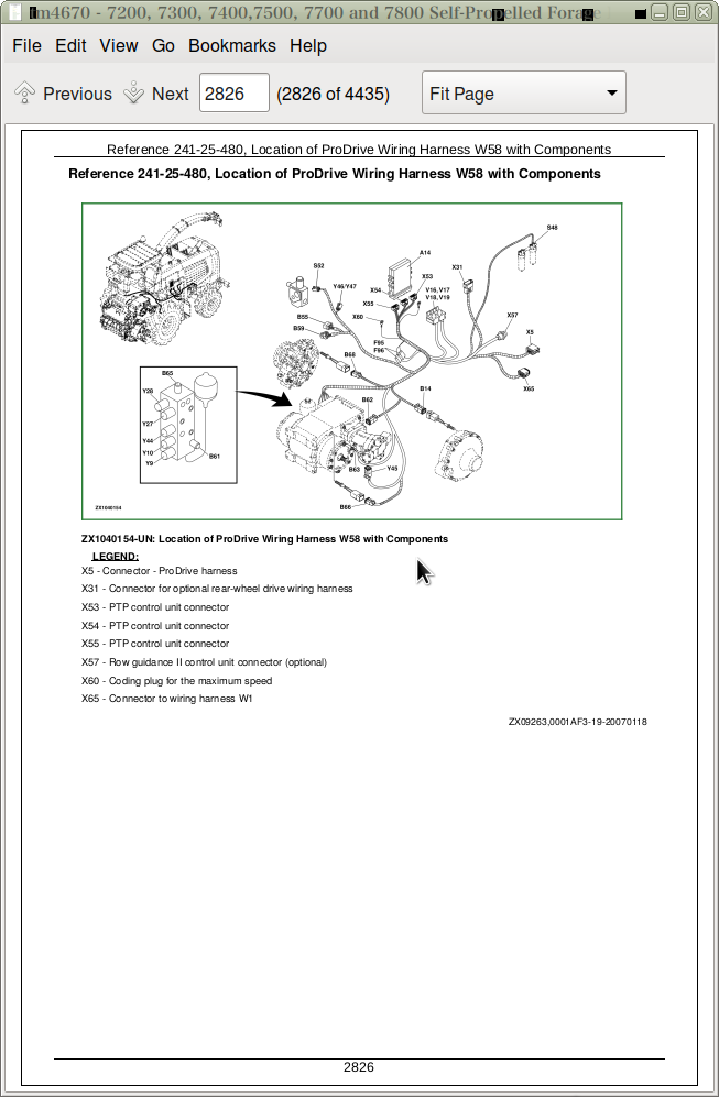
Reference 241-10X-014, Theory of Operation with ProDrive
Reference 241-10X-015, Functional/Diagnostic Schematic of Drive Train Control Functions for ProDrive
Group 10Y: Row Guidance Functions
Reference 241-10Y-001, Row Guidance Functions — Summary of References
Reference 241-10Y-010, Operational Information of Row Guidance Functions
Reference 241-10Y-011, Theory of Operation
Reference 241-10Y-012, Functional/Diagnostic Schematic of Row Guidance Functions I
Reference 241-10Y-012, Functional/Diagnostic Schematic of Row Guidance Functions II
Group 10Z: Stationary Knife Adjust Function
Reference 241-10C-001, Stationary Knife Adjust Function — Summary of References
Reference 241-10Z-010, Operational Information of Stationary Knife Adjust Function
Reference 241-10Z-011, Theory of Operation
Reference 241-10F-012, Functional/Diagnostic Schematic of Stationary Knife Adjust Function
Group 10AA: Spout Control Functions
Reference 241-10AA-001, Spout Control Functions – Summary of References
Reference 241-10AA-010, Operational Information of Spout Control Functions
Reference 241-10AA-011, Theory of Operation
Reference 241-10AA-012, Functional/Diagnostic Schematic of Spout Control Functions
Group 10AB: Trailer Functions
Reference 241-10AB-001, Trailer Functions — Summary of References
Reference 241-10AB-010, Operational Information of Trailer Functions
Reference 241-10AB-011, Theory of Operation
Reference 241-10AB-012, Functional/Diagnostic Schematic of Trailer Functions
Group 10AC: System Interlock Functions
Reference 241-10AC-001, System Interlock Functions — Summary of References
Reference 241-10AC-010, Operational Information of System Interlock Functions
Reference 241-10AC-011, Theory of Operation
Reference 241-10AC-012, Functional/Diagnostic Schematic of System Interlock Functions—from Serial No. 506847
Group 10AD: On-Board Diagnostic Functions
Reference 241-10AD-001, On-Board Diagnostic Functions — Summary of References
Reference 241-10AD-010, Operational Information of On-Board Diagnostic Functions
Reference 241-10AD-011, Theory of Operation
Group 10AE: CAN Bus System Functions
Reference 241-10AE-001, CAN Bus System Functions — Summary of References
Reference 241-10AE-010, Operational Information of CAN Bus System Functions
Reference 241-10AE-011, Theory of Operation
Reference 241-10AE-012, Functional Schematic of CAN Bus System Functions
Group 10AF: GreenStar Display/Moisture Sensor
Reference 241-10AF-001, GreenStar Display — Summary of References
Reference 241-10AF-010, Operational Information
Reference 241-10AF-011, Theory of Operation
Reference 241-10AF-012, Functional/Diagnostic Schematic
Group 10AG: AutoTrac
Reference 241-10AG-001, GreenStar Display — Summary of References
Reference 241-10AG-001, Operational Information
Reference 241-10AG-002, Theory of Operation
Reference 241-10AG-003, Functional/Diagnostic Schematic
Group 13: Functional Schematics – Sections 1 to 41
Reference 241-13-001, Summary of References
Reference 241-13-005, Sections 1 and 2 (Starting Functions and Power Distribution)
Reference 241-13-010, Section 3A (ECU - Cummins Engine)
Reference 241-13-015, Section 3B (Level 9 ECU)
Reference 241-13-020, Section 3C (Level 6 ECU)
Reference 241-13-025, Section 4 (OCP)
Reference 241-13-030, Section 5A (Control of Main Clutch, Feed Rolls and Automatic Lubrication)
Reference 241-13-035, Section 5B (Control of Main Clutch, Feed Rolls and Automatic Lubrication - with IV LOC)
Reference 241-13-040, Section 6 (RCP)
Reference 241-13-045, Section 7 (ARC, Air Conditioning and Quick Stop Functions)
Reference 241-13-050, Section 8 (ARC, Switches)
Reference 241-13-055, Section 9 (ARC, Switches)
Reference 241-13-060, Section 10 (ARC, Switches)
Reference 241-13-065, Sections 11 and 12 (Multi-Function Lever, Knock Sensors)
Reference 241-13-070, Section 13A (SIG)
Reference 241-13-075, Section 13B (SIG - with IV LOC)
Reference 241-13-080, Section 14 (SPF, Knife Sharpening Function)
Reference 241-13-085, Section 15 (SPF, Stationary Knife and Kernel Processor Motor)
Reference 241-13-090, Section 16 (SPF, Reverse Function, Sensors)
Reference 241-13-095, Section 17A (SPF, Gear Lock, Air-Conditioning System)
Reference 241-13-100, Section 17B (SPF, Electric Clutch, Air-Conditioning System - with IV LOC)
Reference 241-13-105, Section 18A (SPF, Sensors from Ser. No. 508100)
Reference 241-13-110, Section 18B (SPF, Sensors Up To Ser. No. 508099)
Reference 241-13-115, Section 19A (SPF, Solenoid Valves)
Reference 241-13-120, Section 19B (SPF, Solenoid Valves - with IV LOC)
Reference 241-13-125, Section 20 (SPF, Liquid Injection Pump)
Reference 241-13-130, Section 21 (SPF, Spout Control)
Reference 241-13-135, Section 22 (SPF, AHC Sensors)
Reference 241-13-140, Section 23A (SPF, Left Turn Signal)
Reference 241-13-145, Section 23B (SPF, Turn Signal with ProDrive)
Reference 241-13-150, Section 24A (SPF, Right Turn Signal)
Reference 241-13-155, Section 24B (Main Control Unit, IV LOC Control)
Reference 241-13-160, Section 25 (Lighting)
Reference 241-13-165, Section 26A (Work Lights)
Reference 241-13-170 Section 26B (Work Lights - France and Italy)
Reference 241-13-175, Section 27A (Halogen Work Lights)
Reference 241-13-180, Section 27B (Xenon (HID) Work Lights)
Reference 241-13-185, Sections 28 and 29 (Rear Work Lights)
Reference 241-13-190, Sections 30 and 31 (Beacon Light, Air-Conditioning System)
Reference 241-13-195, Section 32 (Wiper/Washer System)
Reference 241-13-200, Section 33 (Radio, Seat Compressor, Relay Tester)
Reference 241-13-205, Sections 34 and 35 (Access Lighting, Kernel Processor Lifting Device)
Reference 241-13-210, Section 36A (PTP)
Reference 241-13-215, Section 36B (PTP, with RGC II)
Reference 241-13-220, Section 36C (Row Guidance II with 3-Speed Transmission)
Reference 241-13-225, Section 36D (RGC I with Two-Wheel Drive for Model Year 2006)
Reference 241-13-230, Section 37 (RDC)
Reference 241-13-235, Section 38 (Rear View Mirrors)
Reference 241-13-240, Section 39 (AMS)
Reference 241-13-245, Section 40 (Liquid Injection Pump)
Reference 241-13-250, Section 41 (Wagon Dump)
Reference 241-13-255, Section 42 (Automatic Spout Positioning)
Reference 241-13-260, Section 43, (AutoTrac)
Group 20: Wiring and Harness Diagrams, Connectors and Components
Reference 241-20-14, Component Survey
Reference 241-20-15, Automatic Lubrication Control A15
Connector - Rear Wheel Drive Control Unit (RDC) W9, A19
Connector - Heater Valve W26, A43
Reference 241-20-16, Cutterhead/Fan Alarm Horn, Rear B3
Reference 241-20-17, Hydrostatic Oil Temperature Switch B6
Reference 241-20-18, Hydrostatic Oil Filter Pressure Switch B7
Reference 241-20-19, Hydrostatic Charge Pressure Switch (13 bar), B8
Reference 241-20-20, Ground Speed Sensor, Front Left, B14
Reference 241-20-21, ATC High Pressure Switch B18
Reference 241-20-22, Rear Axle Pressure Sensor B22
Reference 241-20-23, Rear Axle Speed Sensor B23
Reference 241-20-24, Reverse Travel Alarm B30
Reference 241-20-25, Hydrostatic Pump Pressure Sensor, Reverse, B55
Reference 241-20-26, Hydrostatic Pump Pressure Sensor, Forward, B59
Reference 241-20-27, Pressure Switch - ProDrive Transmission, B61
Reference 241-20-28, Transmission Oil Temperature Switch, ProDrive Transmission, B62
Reference 241-20-29, Sensor for Hydrostatic Motor Speed B63
Connector - Multi-Function Lever W27, B64
Reference 241-20-30, Sensor for Park Brake Pressure, ProDrive Transmission, B65
Reference 241-20-31, Transmission Speed Sensor B66
Reference 241-20-32, Wheel Angle Sensor WAS B67
Reference 241-20-33, Ground Speed Sensor, Front Right, B68
Reference 241-20-34, Spout Cap Position Sensor B70
Reference 241-20-35, Spout Sensor, Raise/Lower, B71
Reference 241-20-36, Sensor for Spout Direction of Rotation, B72
Reference 241-20-37, Spout Work Lights E6 and E7
Reference 241-20-38, Rear Work Light E9
Reference 241-20-39, License Plate Light E10
Reference 241-20-40, Spout Brake Light and Spout Clearance Light H47 and E27
Reference 241-20-41, Rotary Air Screen Motor M2
Reference 241-20-42, Washer Pump M5
Reference 241-20-43, Spout Cap Motor M6
Reference 241-20-44, Side Window Washer Pump M17
Reference 241-20-45, Rear Wheel Potentiometer R12
Reference 241-20-46, Transmission Oil Filter Pressure Switch S48
Reference 241-20-47, Reverse Drive Switch of Hydrostatic Pump S54
Reference 241-20-48, Coolant Level Switch S57
Reference 241-20-49, Rotary Air Screen Speed Switch S67
Reference 241-20-50, Trailer Outlet Socket X0
Connector - Rear of Cab W1, X1
Connector - Rear of Cab W25, X1
Connector - Rear of Cab W1, X2
Connector - Rear of Cab W25, X2
Connector - Rear of Cab W1, X3
Connector - Rear of Cab W25, X3
Connector - Rear of Cab W1, X4
Connector - Rear of Cab W26, X4
Connector - ProDrive Wiring Harness W58, X5
Connector - Front Harness on Cutterhead W1, X8
Connector - Front Harness on Cutterhead W3, X8
Connector - Front Harness W1, X9
Connector - Front Harness on Cutterhead W3, X9
Reference 241-20-52, Engine Harness Connector X10
Connector - Engine Harness (Level 9) W8, X10
Connector - Engine Harness (Level 6), Model 7300, W13, X10
Connector - Engine Harness, Cummins, W48, X10
Connector - Cab Main Harness W25, X11
Connector - ATC System, W26, X13
Connector - Armrest Harness W27, X17
Diagnostic Connector, CAN-bus, W25, X20
Connector - Metal Detector Control Unit, X21
Connector - SPFH Main Control Unit, X22 J1
Connector - SPFH Main Control Unit, X23 J1
Connector - SPFH Main Control Unit, X24 J3
Connector - SPFH Main Control Unit, X25 J3
Connector - Kernel Processor, X26
Connector - Kernel Processor W29, X26
Connector - GreenStar Control Unit, X27
Connector - Cutterhead Harness (with GreenStar), X30
Connector - ProDrive Wiring Harness W58, X31
Reference 241-20-54, Main Connector X32
Connector - Main Connector W2, X33
Connector - Front Harness W3, X38
Connector - Fuel Injection Nozzle W8, X40
Connector - CAN-bus W4, X41
Connector - Engine Control Unit (Level 6), Model 7300, W13, X42
Connector - Engine Control Unit (JD Level 9), W8, X43
Connector - Engine Control Unit (JD Level 9), W8, X44
Connector - ECU, W15, X45
Connector - Row Guidance Solenoid Valves, W2, X49
Connector - Row Guidance Solenoid Valves, W11, X49
Connector - Platform Harness, W2, X50
Connector - Platform Harness, W28, X50
Connector - Spout Harness W1, X51
Connector - Row Guidance I Control Unit W7, X53
Connector - Row Guidance I Control Unit W7, X54
Connector - Row Guidance II Control Unit W7, X54
Connector - ProDrive Control Unit W7, X55
Connector - Row Guidance I Control Unit W7, X55
Connector - Row Guidance I Control Unit W7, X56
Connector - Row Guidance I Control Unit W7, X57
Connector - Row Guidance II Control Unit W7, X57
Connector - ProDrive Wiring Harness W58, X53
Connector - ProDrive Wiring Harness W58, X54
Connector - ProDrive Wiring Harness W58, X55
Connector - ProDrive Wiring Harness W58, X57
Reference 241-20-58, Row Guidance Adapter Harness X55
Connector - Row Guidance I Control Unit W7, X57
Connector - Row Guidance II Control Unit W7, X57
Connector - JDLink W47, X59
Reference 241-20-60, Brake Light Connector with ProDrive, X65
Connector to W01, W58, X65
Reference 241-20-61, L.H. Tail Light Connector X74
Reference 241-20-62, R.H. Tail Light Connector X79
Reference 241-20-63, Solenoid Valve Harness Connector X81
Connector - Solenoid Valve Harness W46, X81A
Connector - Solenoid Valve Harness W46, X81B
Connector - Engine Control Unit (Level 6), Model 7300, W13, X91
Connector - Engine Control Unit (Level 6), Model 7300, W13, X92
Connector - Fuel Injection Nozzle Harness W15, X94
Reference 241-20-64, Header Up Proportional Valve Y7
Reference 241-20-65, Header Down Proportional Valve Y8
Reference 241-20-66, Second Gear Solenoid Valve (ProDrive Transmission), Y9
Reference 241-20-67, First Gear Solenoid Valve (ProDrive Transmission), Y10
Reference 241-20-68, Proportional Valve, Reverse (IVLOC), Y18
Reference 241-20-69, Proportional Valve, Forward (IVLOC), Y19
Reference 241-20-70, Kernel Processor Cut-Off Solenoid Valve Y22
Reference 241-20-71, Kernel Processor Cut-Off Solenoid Valve Y22.1
Reference 241-20-72, Park Brake Relief Valve Y27
Reference 241-20-73, Park Brake Relief Valve Y28
Reference 241-20-74, Unload Valve 1, Y29
Reference 241-20-75, Main Clutch Valve Y33
Reference 241-20-76, Main Clutch Valve Y33.1
Reference 241-20-77, Rear Axle Proportional Valve Y41
Reference 241-20-78, Differential Lock Solenoid Valve Y44
Reference 241-20-79, Front Hydrostatic Motor Adjusting Valve Y45
Reference 241-20-80, Hydrostatic Pump Adjusting Valves Y46/Y47
Group 21: Wiring and Harness Diagrams (Splices)
Splice X035, W1
Splice X056A, W1
Splice X056B, W1
Splice X057, W1
Splice X066B, W1
Splice X066D, W1
Splice X104, W1
Splice X105, W1
Splice X115F, W1
Splice X125F, W1
Splice X141B, W1
Splice X151, W1
Splice X152, W1
Splice X157, W1
Splice X202, W1
Splice X241, W1
Splice X246, W1
Splice X246, W1
Splice X296, W1
Splice X297, W1
Splice X304, W1
Splice X305, W1
Splice X310E, W1
Splice X336, W1
Splice X348, W1
Splice X349, W1
Splice X431, W1
Splice X432, W1
Splice X435, W1
Splice X453A, W1
Splice X454A, W1
Splice X472, W1
Splice X476, W1
Splice X478, W1
Splice X478A, W1
Splice X483, W1
Splice X552, W1
Splice X595, W1
Splice X065, W2
Splice X115A, W2
Splice X118, W2
Splice X122B, W2
Splice X128, W2
Splice X272, W2
Splice X272A, W2
Splice X310, W2
Splice X310, W2
Splice X310A, W2
Splice X310B, W2
Splice X310G, W2
Splice X363, W3
Splice X422A, W2
Splice X455, W2
Splice X145, W3
Splice X272, W3
Splice X333, W3
Splice X115C, W5
Splice X116B, W5
Splice X118C, W5
Splice X125B, W5
Splice X128F, W5
Splice X132, W5
Splice X221, W5
Splice X241A, W5
Splice X246A, W5
Splice X310, W5
Splice X310A, W5
Splice X310B, W5
Splice X310C, W5
Splice X310D, W5
Splice X310E, W5
Splice X310F, W5
Splice X319, W5
Splice X422B, W5
Splice X496, W5
Splice X502A, W5
Splice X050X, W7
Splice X050X, W7
Splice X245A, W7
Splice X248B, W7
Splice X471D, W7
Splice X047, W8
Splice X050, W8
Splice X238, W8
Splice X315, W8
Splice X318, W8
Splice X050, W9
Splice X502, W9
Splice X252, W11
Splice X047, W13
Splice X310, W13
Splice X328, W13
Splice X047, W14
Splice X288, W14
Splice X310, W14
Splice X328, W14
Splice X397, W13
Splice X008, W25
Splice X043, W25
Splice X050, W25
Splice X050G, W25
Splice X057, W25
Splice X072, W25
Splice X087, W25
Splice X103, W25
Splice X103D, W25
Splice X103E, W25
Splice X104, W25
Splice X127, W25
Splice X157, W25
Splice X178, W25
Splice X179, W25
Splice X183, W25
Splice X144, W25
Splice X310-0, W25
Splice X310-1, W25
Splice X310-2, W25
Splice X310-3, W25
Splice X310-4, W25
Splice X310-5, W25
Splice X310-5, W25
Splice X310-UU, W25
Splice X476, W25
Splice X552, W25
Splice X911, W25
Splice X974-0, W25
Splice X974-1, W25
Splice X974-2, W25
Splice X975-0, W25
Splice X975-1, W25
Splice X975-2, W25
Splice X974-3, W25
Splice X974-4, W25
Splice X974-5, W25
Splice X975-3, W25
Splice X975-4, W25
Splice X975-5, W25
Splice X980-0, W25
Splice X982-0, W25
Splice X035, W26
Splice X062, W26
Splice X310, W26
Splice X431, W26
Splice X483, W26
Splice X751, W26
Splice X103, W27
Splice X152, W27
Splice X254, W27
Splice X310A, W27
Splice X310B, W27
Splice X310, W28
Splice X272, W29
Splice X363, W29
Splice X310, W34
Splice X453, W34
Splice X454, W34
Splice X038, W46
Splice X172, W46
Splice X173, W46
Splice X174, W46
Splice X176, W46
Splice X196, W46
Splice X197, W46
Splice X198, W46
Splice X199, W46
Splice X204, W46
Splice X262, W46
Splice X452, W46
Splice X002J, W48
Splice X002H, W48
Splice X310, W48
Splice X310G, W48
Splice X328, W48
Splice X329, W48
Splice X310AA, W57
Splice X417, W57
Splice X416, W57
Splice X419, W57
Splice X484A, W57
Splice X050, W58
Splice X050K, W58
Splice X050M, W58
Splice X123A, W58
Splice X248, W58
Splice X310, W58
Splice X502, W58
Splice X537, W58
Splice X549, W58
Splice X559, W58
Splice X562, W58
Splice X588, W58
Splice X594, W58
Splice X612, W58
Group 25: Location of Wiring Harnesses
Reference 241-25-001, Wiring and Harness Diagrams and Harness Location — Summary of References
Reference 241-25-011, Wiring Harness Survey
Reference 241-25-012, Control Unit Survey
Reference 240-15-013, Component Identification Table
Reference 241-20-14, Component Survey
Reference 241-25-200, Location of Distribution Wiring Harness With Load Center W1 and W33 With Components
Reference 241-25-210, Location of Wiring Harness W2 and W21 for 676 Header with Components
Reference 241-25-220, Location of Platform Wiring Harness W2, W23 and W24 With Components
Reference 241-25-230, Location of Front Wiring Harness W3 and W3A With Components
Reference 241-25-240, Location of Row Guidance Feeler Wiring Harness W4 and W10 With Components
Reference 241-25-250, Location of Main Wiring Harness W5 With Components
Reference 241-25-260, Location of Row Guidance Feeler Outlet Wiring Harness W6 With Components
Reference 241-25-270, Location of Row Guidance Adapter Wiring Harness W7 With Components
Reference 241-25-280, Location of Row Guidance II Adapter Wiring Harness W7 With Components
Reference 241-25-290, Location of Engine Wiring Harness W8 and W31 With Components (8.1 Liter JD Engine, JD ECU Level 9)
Reference 241-25-300, Location of 4WD Adapter Wiring Harness W9 With Components
Reference 241-25-310, Location of Row Guidance Solenoid Valve Wiring Harness W11 With Components
Reference 241-25-320, Location of Row Guidance II Solenoid Valve Wiring Harness W11 With Components
Reference 241-25-330, Location of Engine Wiring Harness W13 and W31, JD ECU Level 6 With Components
Reference 241-25-340, Location of Engine Wiring Harness W14 and W31, JD ECU Level 6 With Components
Reference 241-25-350, Location of Injector Valve Wiring Harness W15 With Components, (7300, 7400, 7500)
Reference 241-25-360, Location of Battery and Ground Cables W16, W17 and W19 With Components
Reference 241-25-370, Location of Kernel Processor Electric Lift Harness W20 With Components
Reference 241-25-375, Location of Cab Wiring Harness W25 and W33 With Components
Reference 241-25-380, Location of Automatic Temperature Control Wiring Harness W26 With Components
Reference 241-25-390, Location of Armrest Wiring Harness W27 With Components
Reference 241-25-400, Location of Steering Column Wiring Harness W28 With Components
Reference 241-25-410, Location of Kernel Processor Wiring Harness W29 With Components
Reference 241-25-420, Location of Spout Wiring Harness W32 and W34 With Components
Reference 241-25-430, Location of Spout Wiring Harness W32 and W34A/B With Components
Reference 241-25-440, Location of Mirror Power Supply and Adjusting Wiring Harness W38 and W39 With Components
Reference 241-25-450, Location of JDLink Wiring Harness W47 with Components
Reference 241-25-460, Location of AutoTrac Wiring Harness W56 with Components
Reference 241-25-470, Location of Trailer Dump Wiring Harness W57 with Components
Reference 241-25-480, Location of ProDrive Wiring Harness W58 with Components
Section 245: Control Units
Group 05: Operation and General Information on Diagnostics
Reference 245-05-001, Operation and General Information on Diagnostics — Summary of References
Reference 245-05-002, General Operation and Entering the Program Mode
Reference 245-05-003, Access Addresses and Diagnostic Trouble Codes
Reference 245-05-004, Quick Procedure - Access to Diagnostic Trouble Codes
Reference 245-05-005, Quick Procedure - Access to Diagnostic Addresses
Reference 245-05-011, Power Train Control Unit - Summary of Addresses
Reference 245-05-012, Engine Control Unit — Summary of Addresses
Reference 245-05-013, JDLink Control Unit — Summary of Addresses
Reference 245-05-016, Armrest Control Unit - Summary of Addresses
Reference 245-05-017, Overhead Control Panel Control Unit — Summary of Addresses
Reference 245-05-018, Corner Post Control Unit — Summary of Addresses
Reference 245-05-019, RGC - Row Guidance Control Unit Up to Model Year 2005, On-Board Diagnostic Addresses
Reference 245-05-019b, RGC - Row Guidance Control Unit From Model Year 2006, On-Board Diagnostic Addresses
Reference 245-05-019c, SSU - AutoTrac Control Unit
Reference 245-05-020, Metal Detector Control Unit - Summary of Addresses
Reference 245-05-021, SPFH Main Control Unit — Summary of Addresses
Reference 245-05-022, System Beep Mode
Reference 245-05-023, Limited System Beep Mode
Reference 245-05-024, Analog Beep Mode
Reference 245-05-025, Digital Beep Mode
Reference 245-05-026, Frequency Beep Mode
Reference 245-05-027, Reset Function
Reference 245-05-028, Storing Dealer Setting
Reference 245-05-031, Using On-Board Diagnostic Addresses For Diagnostic Support
Reference 245-05-050, Approved Software for Control Units
Group 06: Test Equipment
Reference 245-06-001, Special Tools
Reference 245-06-002, Special Tool DFLX12 for CAN Bus Check
Group 20: CAN Bus System
Reference 245-20-001, CAN Bus System — Summary of References
Reference 245-20-002, CAN Bus System
Reference 245-20-003, CAN Bus System on Self-Propelled Forage Harvesters
Reference 245-20-006, CAN Bus Check
Group AMS: GreenStar Control Unit (AMS)
Special Tools
Circuit/Harness Test for GreenStar Display A28
Circuit/harness test for mobile processor A29
Circuit/Harness Test for GPS Receiver (A30)
Circuit/Harness Test for Printer (A32)
Circuit/Harness Test for Feed Roll Distance Sensor (B58)
Check Feed Roll Distance Sensor (B58) Calibration
Circuit/Harness Test for Moisture Sensor (A44)
Moisture Sensor (A44) - Operation
Moisture Sensor (A44) - Adjustments
Job Computer (A27) - Operation
Group ARC: Armrest Control Unit (ARC)
Reference 245-ARC-001, Armrest Control Unit — Summary of References
Reference 245-ARC-002, Armrest Control Unit — Calibration, Input and Output Addresses
Reference 245-ARC-003, Armrest Control Unit — Calibration Survey
Reference 245-ARC-100, General Circuit Test
Reference 245-ARC-101, Circuit / Harness Test For Inlet Temperature Sensor B49
Reference 245-ARC-102, Circuit / Harness Test For Outlet Temperature Sensor B50
Reference 245-ARC-103, Circuit / Harness Test For Cab Temperature Sensor B51
Reference 245-ARC-104, Circuit / Harness Test For Evaporator Core Temperature Sensor B52
Reference 245-ARC-105, Circuit / Harness Test For Solar Sensor B19
Reference 245-ARC-106, Circuit / Harness Test For Row Guidance Set Point Potentiometer R10
Reference 245-ARC-107, Circuit / Harness Test For Water Valve Actuator A43
Reference 245-ARC-108, Circuit / Harness Test For Quick Stop Switch S23
Reference 245-ARC-109, Circuit / Harness Test For Harvesting Unit On / Reverse Switch S31
Reference 245-ARC-110, Circuit / Harness Test For Pressurizer Blower Motor M20
Reference 245-ARC-111, Circuit / Harness Test For Recirculation Blower Motor M3
Reference 245-ARC-112, Circuit / Harness Test For Low Pressure Switch B17
Reference 245-ARC-113, Circuit / Harness Test For Multi-Function Lever A16
Reference 245-ARC-200, Armrest Control Unit — Theory of Operation
Reference 245-ARC-201, Armrest Control Unit — System Block Diagram
Reference 245-ARC-202, Armrest Control Unit — Inputs
Reference 245-ARC-203, Armrest Control Unit — Outputs
Group ECU: Engine Control Unit (ECU)
Reference 245-ECU-001, Engine Control Unit — Summary of References
Reference 245-ECU-200, Engine Control Unit — Theory of Operation
Reference 245-ECU-201, Engine Control Unit — System Block Diagram
Group JDL: JDLink Control Unit (JDL)
Reference 245-JDL-001, JDLink Control Unit — Summary of References
Reference 245-JDL-002, JDLink Control Unit — Calibration, Input and Output Addresses
Reference 245-JDL-200, JDLink Control Unit — Theory of Operation
Reference 245-JDL-201, JDLink Control Unit — System Block Diagram
Group OCP: Overhead Control Panel Control Unit (OCP)
Reference 245-OCP-001, Overhead Control Panel Control Unit — Summary of References
Reference 245-OCP-002, Overhead Control Panel Control Unit — Calibration, Input and Output Addresses
Reference 245-OCP-003, Calibration Survey
Reference 245-OCP-100, General Circuit Test
Reference 245-OCP-101, Circuit / Harness Test For Automatic Function Control Panel A9B
Reference 245-OCP-200, Overhead Control Panel Control Unit — Theory of Operation
Reference 245-OCP-201, Overhead Control Panel Control Unit — System Block Diagram
Reference 245-OCP-202, Overhead Control Panel Control Unit — Inputs
Reference 245-OCP-203, Overhead Control Panel Control Unit — Outputs
Group PTP: ProDrive Control Unit (PTP)
Reference 245-PTP-001, Summary of References
Towing the Vehicle
Reference 245-PTP-100, General Circuit Test
Reference 245-PTP-101, Circuit / Harness Test For Directly Controlled Electromagnetic Valves
Reference 245-PTP-102, Circuit / Harness Test For Two-Terminal Speed Sensors
Reference 245-PTP-103, Circuit / Harness Test For Three-Terminal Pressure Sensors
Reference 245-PTP-104, Circuit / Harness Test For Four-Terminal Speed Sensors
Reference 245-PTP-105, Circuit/Harness Test for Transmission Oil Temperature Sensor B62
Reference 245-PTP-106, Circuit/Harness Test for Ground Speed Drive Lever B64
Reference 245-PTP-107, Circuit/Harness Test for Wheel Angle Sensor B67 (WAS)
Reference 245-PTP-108, Circuit/Harness Test for Transmission Oil Filter Pressure Switch S48
Reference 245-PTP-109, Circuit / Harness Test for Brake Accumulator Pressure Switch S52
Reference 245-PTP-200, Quick Procedure - Access to On-Board Diagnostic Addresses
Reference 245-PTP-201, PTP Addresses — Power Train Control Unit, Survey
Reference 245-PTP-202, Transmission Control Unit PTP — Input and Output Addresses
Reference 245-PTP-203, Transmission Control Unit PTP — Calibration Survey
Reference 245-PTP-205, Maximum Speed Presetting
Address PTP/RCP 100 Calibration — Tire Size Calibration
Reference 245-PTP-207, Address PTP 101 Calibration — Ratio Calibration (Front/Rear)/Steering Angle Calibration
Reference 245-PTP-208, Address PTP 102 Calibration — Park Brake Override
Reference 245-PTP-209, Address PTP 103 Calibration — Neutral Position Switch Override
Reference 245-PTP-210, Address PTP 104 Calibration — Seat Switch Override
Reference 245-PTP-211, Address PTP 105 Calibration — Calibration, First Or Second Gear Only
Reference 245-PTP-212, Address PTP 110 Calibration — Multi-Function Lever Calibration
Reference 245-PTP-213, Address PTP 111 Calibration — Solenoid Valve Calibration
Reference 245-PTP-214, Address PTP 112 Calibration — Pump Delivery Calibration
Reference 245-PTP-215, Address PTP 113 Calibration — Front Axle Motor Calibration
Reference 245-PTP-216, Address PTP 114 Calibration — Rear Axle Motor Calibration
Reference 245-PTP-217, Address PTP 115 Calibration — Calibration of Engagement Point (1st and 2nd Gear Clutches)
Reference 245-PTP-218, ProDrive Control Unit — Inputs
Reference 245-PTP-219, ProDrive Control Unit — Outputs
Reference 245-PTP-220, ProDrive Control Unit — Setting for Row Guidance
Group RCP: Cornerpost Control Unit (RCP)
Reference 245-RCP-001, Corner Post Control Unit — Summary of References
Reference 245-RCP-002, Corner Post Control Unit — Calibration, Input and Output Addresses
Reference 245-RCP-003, Calibration Survey
Reference 245-RCP-100, General Circuit Test
Reference 245-RCP-101, Circuit / Harness Test For Temperature Set Point Potentiometer R4
Reference 245-RCP-102, Circuit / Harness Test For Fan Speed Set Point Potentiometer R5
Reference 245-RCP-103, Circuit / Harness Test For Backlight Set Point Potentiometer R8
Reference 245-RCP-104, Circuit / Harness Test For Mode Select Switch S6
Reference 245-RCP-105, Circuit / Harness Test For Fan Speed Auto Mode Switch S5
Reference 245-RCP-106, Circuit/Harness Test for Spout Cap Sensor (B70)
Reference 245-RCP-107, Circuit/Harness Test for Spout Tilt Sensor (B71)
Reference 245-RCP-108, Circuit/Harness Test for Spout Rotation Angle Sensor (B72)
Reference 245-RCP-200, Corner Post Control Unit — Theory of Operation
Reference 245-RCP-201, Corner Post Control Unit - System Block Diagram
Reference 245-RCP-202, Corner Post Control Unit — Inputs
Reference 245-RCP-203, Corner Post Control Unit — Outputs
Group RDC: Rear Wheel Drive Control Unit (RDC)
Reference 245-RDC-001, Rear Wheel Drive Control Unit — Summary of References
Reference 245-RDC-002, Rear Wheel Drive Control Unit — Calibration, Input and Output Addresses
Reference 245-RDC-100, General Circuit Test
Reference 245-RDC-101, Circuit / Harness Test For Rear Wheel Speed Sensor B23
Reference 245-RDC-102, Circuit / Harness Test For Pressure Sensor B22
Reference 245-RDC-103, Circuit / Harness Test For Rear Hydrostatic Motor Proportional Valve Y41
Reference 245-RDC-200, Rear Wheel Drive Control Unit — Theory of Operation
Reference 245-RDC-201, Rear Wheel Drive Control Unit — System Block Diagram
Reference 245-RDC-202, Rear Wheel Drive Control Unit — Inputs
Reference 245-RDC-203, Rear Wheel Drive Control Unit — Outputs
Group RGCI: Row Guidance I Control Unit (RGC I)
Reference 245-RGC I-001, Row Guidance Control Unit — Summary of References
Reference 245-RGC I-002, Row Guidance Control Unit — Calibration, Input and Output Addresses
Reference 245-RGC I-114, Calibration Survey
Reference 245-RGC I-100, General Circuit Test
Reference 245-RGC-101, Survey of Steering Sensor Versions
Reference 245-RGC-102, Distinguish RGC I and RGC II
Reference 245-RGC I-103, Circuit/Harness Test For Steering Sensor R12
Reference 245-RGC I-101, Circuit/Harness Test For L.H. Feeler R13
Reference 245-RGC I-102, Circuit/Harness Test For R.H. Feeler R14
Reference 245-RGC I-104, Circuit/Harness Test For Proportional Valves Y36 and Y37
Reference 245-RGC I-105, Circuit/Harness Test For Hydraulic Pressure Switch S38
Reference 245-RGC I-200, Row Guidance Control Unit — Theory of Operation
Reference 245-RGC I-201, Row Guidance Control Unit — System Block Diagram
Reference 245-RGC I-202, Row Guidance Control Unit — Inputs
Reference 245-RGC I-203, Row Guidance Control Unit — Outputs
Group RGCII: Row Guidance II Control Unit (RGC II)
Reference 245-RGC II-001, Row Guidance Control Unit — Summary of References
Reference 245-RGC II-002, Armrest Control Unit — Calibration, Input and Output Addresses
Reference 245-RGC II-004, Calibration Survey
Reference 245-RGC-101, Survey of Steering Sensor Versions
Reference 245-RGC-102, Distinguish RGC I and RGC II
Reference 245-RGC II-110, Operational Check Of Steering Wheel Position Sensor B69 (SID)
Reference 245-RGC II-111, Circuit/Harness Test For Steering Wheel Position Sensor B69 (SID)
Reference 245-RGC II-112, Circuit/Harness Test For Wheel Angle Sensor B67 (WAS)
Reference 245-RGC II-113, Circuit/Harness Test of Steering Valve Y40
Reference 245-RGC II-203A, Row Guidance Control Unit — Inputs and Outputs (From Model Year 2006, With Four-Wheel Drive)
Reference 245-RGC II-210, Row Guidance Control Unit — Setting for ProDrive
Group SIG: Metal Detector Control Unit (SIG)
Reference 245-SIG-001, Metal Detector Control Unit — Summary of References
Reference 245-SIG-002, Metal Detector Control Unit — Calibration, Input and Output Addresses
Reference 245-SIG-210, Calibration Survey
Reference 245-SIG-100, General Circuit Test
Reference 245-SIG-101, Circuit / Harness Test For Sound Sending Units B26, B27
Reference 245-SIG-102, Circuit / Harness Test For Metal Detector Sensor B24
Reference 245-SIG-103, Circuit / Harness Test For Feedroll Stop Pawl Solenoid Y3 (Only IVLOC)
Reference 245-SIG-104, Circuit / Harness Test For Stop Pawl Solenoid Y34 (Only IVLOC)
Reference 245-SIG-105, Circuit / Harness Test For Control Solenoid Valve Y22 For Kernel Processor Drive Belt Tension
Reference 245-SIG-106, Circuit / Harness Test For Stop Pawl Solenoid Y39 (Only Four- Speed LOC)
Reference 245-SIG-200, Metal Detector Control Unit — Theory of Operation
Reference 245-SIG-201, Metal Detector Control Unit — System Block Diagram
Reference 245-SIG-202, Metal Detector Control Unit — Inputs
Reference 245-SIG-203, Metal Detector Control Unit — Outputs
Group SPF: SPFH Main Control Unit (SPF)
Reference 245-SPF-001, SPFH Main Control Unit — Summary of References
Reference 245-SPF-002, SPFH Main Control Unit — Calibration, Input and Output Addresses
Reference 245-SPF-003, Calibration Survey
Reference 245-SPF-100, General Circuit Test
Reference 245-SPF-101, Circuit / Harness Test For Turn Signal Switch S43
Reference 245-SPF-102, Circuit / Harness Test For Central Lubrication Control Unit A15
Reference 245-SPF-103, Circuit / Harness Test For Sharpening Door Motor M18
Reference 245-SPF-104, Circuit / Harness Test For Sharpening Door Position Sensor R9
Reference 245-SPF-105, Circuit / Harness Test For Rotary Suction Screen Drive Motor M2
Reference 245-SPF-106, Circuit / Harness Test For Seat Switch S44
Reference 245-SPF-107, Circuit / Harness Test For Manual Cutterhead Reverse Switch S53
Reference 245-SPF-108, Circuit / Harness Test For Powr-Savr Interlock Relay 2K11
Reference 245-SPF-109, Circuit / Harness Test For LOC Neutral Relay 1K22
Reference 245-SPF-110, Circuit / Harness Test For Stationary Knife Motor M11, M12
Reference 245-SPF-111, Circuit / Harness Test For Stationary Knife Motor Impulse Sensor B47, B48
Reference 245-SPF-112, Circuit / Harness Test For Kernel Processor Motor M13, M14
Reference 245-SPF-113, Circuit / Harness Test For Kernel Processor Motor Impulse Sensor B53, B54
Reference 245-SPF-114, Circuit / Harness Test For Cutterhead Speed Sensor B10
Reference 245-SPF-115, Circuit / Harness Test For Feedroll Speed Sensor B16
Reference 245-SPF-116, Circuit / Harness Test For LOC Neutral Switches S32, S33
Reference 245-SPF-117, Circuit / Harness Test For Transmission Third Gear Switch S21
Reference 245-SPF-118, Circuit / Harness Test For Park Brake Switch S56
Reference 245-SPF-119, Circuit / Harness Test For Main Clutch Switch S29
Reference 245-SPF-120, Circuit / Harness Test For Stone Sweep Motor M10
Reference 245-SPF-121, Circuit / Harness Test For Sharpening Stone Position Sensor R6
Reference 245-SPF-122, Circuit / Harness Test For Alternator G4, G5
Reference 245-SPF-123, Circuit / Harness Test For High Pressure Switch B18
Reference 245-SPF-124, Circuit / Harness Test For Gear Brake Solenoid Valve Y4
Reference 245-SPF-125, Circuit / Harness Test For Feedrolls Forward Solenoid Valve Y5
Reference 245-SPF-126, Circuit / Harness Test For Feedrolls Reverse Solenoid Valve Y6
Reference 245-SPF-127, Circuit / Harness Test For Hydrostatic Oil Temperature Sensor B6
Reference 245-SPF-128, Circuit / Harness Test For Hydraulic Oil Filter Pressure Switch B7
Reference 245-SPF-129, Circuit / Harness Test For Hydrostatic Charge Pressure Switch B8
Reference 245-SPF-130, Circuit / Harness Test For Front Wheel Speed Sensor B12
Reference 245-SPF-131, Circuit / Harness Test For Hydraulic Pressure Control Switch B11 (IVLOC)
Reference 245-SPF-132, Circuit / Harness Test For Hydraulic Oil Filter Pressure Switch B13 (IVLOC)
Reference 245-SPF-133, Circuit / Harness Test For Cutterhead Safety Switch S30
Reference 245-SPF-134, Circuit / Harness Test For Cutterhead Interlock Relay 1K18
Reference 245-SPF-135, Circuit / Harness Test For Proportional Valve Y18 Reverse (IVLOC)
Reference 245-SPF-136, Circuit / Harness Test For Proportional Valve Y19 Forward (IVLOC)
Reference 245-SPF-137, Circuit / Harness Test For Unloading Valve Y29
Reference 245-SPF-138, Circuit / Harness Test For Unloading Valve Y30
Reference 245-SPF-139, Circuit / Harness Test For Reverse Motor Solenoid Valve Y35
Reference 245-SPF-140, Circuit / Harness Test For Header Slow Drive Solenoid Valve Y16
Reference 245-SPF-141, Circuit / Harness Test For Header Fast Drive Solenoid Valve Y17
Reference 245-SPF-142, Circuit / Harness Test For Spout Left Rotation Solenoid Valve Y12
Reference 245-SPF-143, Circuit / Harness Test For Spout Right Rotation Solenoid Valve Y13
Reference 245-SPF-144, Circuit / Harness Test For Spout Fast Rotation Solenoid Valve Y13.1
Reference 245-SPF-145, Circuit / Harness Test For Spout Cap Motor M6
Reference 245-SPF-146, Circuit / Harness Test For Spout Raise Solenoid Valve Y14
Reference 245-SPF-147, Circuit / Harness Test For Spout Lower Solenoid Valve Y15
Reference 245-SPF-148, Circuit / Harness Test For Feedroll Forward Relay 1K17
Reference 245-SPF-149, Circuit / Harness Test For Transmission Reverse Switch S54
Reference 245-SPF-200, SPFH Main Control Unit — Theory of Operation
Reference 245-SPF-201, SPFH Main Control Unit — System Block Diagram
Reference 245-SPF-202, SPFH Main Control Unit — Inputs
Reference 245-SPF-203, SPFH Main Control Unit — Outputs
Group SSU: AutoTrac Control Unit (SSU)
SSU Calibrations
SSU Inputs and Outputs
Section 250: Power Train with 3-Speed Transmission
Group 10: Operational Checks
Reference 250-10-001, Operational Checkout — Summary of References
Reference 250-10-001, Operational Checkout
Reference 250-10-015, Special Tools
Reference 250-10-020, Test Port for Hydrostatic Motor
Reference 250-10-025, Testing Device for Hydrostatic System
Reference 250-10-030, Testing Device for High Pressure Relief Valves (SPFH with 3-Speed Transmission)
Group 15: Tests and Adjustments for 3-Speed Transmission
Reference 250-15-001, Tests and Adjustments—Summary of References
Reference 250-15-010, Specifications of 3-Speed Transmission
Reference 250-15-015, Adjustment of Neutral Position of Hydrostatic System (with 3-Speed Transmission)
Reference 250-15-020, Displacement Control Valve Neutral Adjustment
Reference 250-15-070, Adjustment of Gearshift Linkage (SPFH with 3-Speed Transmission)
Reference 250-15-030, Hydrostatic Charge Pressure Testing (SPFH with 3-Speed Transmission)
Reference 250-15-035, Hydrostatic High Pressure Testing (SPFH with 3-Speed Transmission)
Reference 250-15-040, Pressure Relief Valves (SPFH with 3-Speed Transmission)
Reference 250-15-045, Charge and Flushing Pressure
Reference 250-15-050, Charge and Flushing Pressure Testing (SPFH with 3-Speed Transmission)
Reference 250-15-055, Testing of High Pressure Relief Valves (with 3-Speed Transmission)
Reference 250-15-060, Testing of High Pressure Relief Valves for Forward Travel (with 3-Speed Transmission)
Reference 250-15-070, Testing of High Pressure Relief Valves for Reverse Travel (with 3-Speed Transmission)
Reference 250-15-075, Overload Relief Valve
Group 20: Theory of Operation of 3-Speed Transmission
Reference 250-20-001, Theory of Operation — Summary of References
Reference 250-20-010, Cutterhead Drive
Reference 250-20-020, Bevel Gear Drive, Power Distribution on Machines with Four-Speed Length-of-Cut Transmission up to Serial No. 507478
Reference 250-20-021, Bevel Gear Drive, Power Distribution on Machines with Four-Speed Length-of-Cut Transmission from Serial No. 507479
Reference 250-20-030, Bevel Gear Drive, Power Distribution on Machines with Infinitely Variable Length-of-Cut Transmission up to Serial No. 507478
Reference 250-20-031, Bevel Gear Drive, Power Distribution on Machines with Infinitely Variable Length-of-Cut Transmission from Serial No. 507479
Reference 250-20-040, Bevel Gear Drive Components
Reference 250-20-050, Main Clutch Components
Reference 250-20-060, Hydrostatic and Mechanical Drive Systems
Reference 250-20-070, Hydrostatic Ground Speed Drive, Operation
Reference 250-20-080, Hydrostatic Ground Speed Drive and Four-Wheel Drive Components (SPFH with 3-Speed-Transmission)
Reference 250-20-090, Hydrostatic System Circuit Diagram
Reference 250-20-091, Hydrostatic System Circuit Diagram
Reference 250-20-092, Hydrostatic System Operation
Reference 250-20-093, System Operation in Neutral
Reference 250-20-094, System Operation in Forward
Reference 250-20-095, System Operation in Reverse
Reference 250-20-096, Function of Pilot-Operated Relief Valves
Reference 250-20-100, Operation of Hydrostatic System with Four-Wheel Drive Engaged
Reference 250-20-110, Operation of Hydrostatic System with Four-Wheel Drive Disengaged (SPFH with 3-Speed-Transmission)
Reference 250-20-120, Operation of Variable Displacement Motor with Four-Wheel Drive Engaged (Rear Axle Motor) (SPFH with 3-Speed-Transmission)
Reference 250-20-130, Schematic View of Bent Axis System with Variable Tilt Angle (SPFH with 3-Speed Transmission)
Reference 250-20-135, Hydrostatic System Diagnostics
Reference 250-20-140, Operation of 3-Speed Transmission
Reference 250-20-150, Final Drives (SPFH with 3-Speed-Transmission)
Reference 250-20-160, Transmission Diagnostics (SPFH with 3-Speed-Transmission)
Reference 250-20-170, Hydrostatic System Operation (SPFH with 3-Speed-Transmission)
Reference 250-20-180, Hydrostatic System Component Location (SPFH with 3-Speed-Transmission)
Reference 250-20-200, Four-Wheel Drive Component/Hose Location (SPFH with 3-Speed-Transmission)
Section 251: Power Train, ProDrive Transmission and Four-Wheel Drive
Group 05: Preliminary Checks
Reference 251-05-001 Preliminary Checks, Summary of References
Reference 251-05-010, Preliminary Checks
Reference 251-05-015, ProDrive Transmission Test Connector
Reference 251-05-020, Test Equipment
Group 10: Tests
Reference 251-10-001, Tests, Summary of References
Reference 251-10-015, ProDrive Specifications
Reference 251-10-016, Heating Up Hydraulic Oil
Reference 251-10-017, Hydrostatic System Pressure Test
Reference 251-10-018, Valves and Test Ports on the Hydrostatic Pump
Reference 251-10-019, Valves and Test Ports on the Hydrostatic Motor
Reference 251-10-020, Check Hydrostatic Pump Charge Pressure
Reference 251-10-021, Check Variable Displacement Pressure
Reference 251-10-022, Check Pilot Pressure of Hydrostatic Pump
Reference 251-10-023, Check Case Pressure
Reference 251-10-024, Check Suction Pressure of Charge Pump
Reference 251-10-025, Check High Pressure at Hydrostatic Motor
Reference 251-10-026, Check High Pressure at Four-Wheel Drive Hydrostatic Motor
Reference 251-10-027, High Pressure Test at Hydrostatic Unit
Reference 251-10-028, Adjust Hydrostatic System Neutral Position - ProDrive Transmission
Reference 251-10-029, Diagnostics, Problems with the Hydrostatic Pump and Hydrostatic Motor
Reference 251-10-030, Diagnostics at Hydraulic Oil Cooler
Reference 251-10-031, Diagnostics, Problems with High Oil Temperature
Reference 251-10-045, ProDrive Transmission Pressure Tests
Reference 251-10-050, Location of Hydraulic Transmission Control Valves
Reference 251-10-053, Hydraulic Circuit Diagram of Hydraulic Transmission Control
Reference 251-10-055, Location of Hydraulic Transmission Control Connections
Group 15: Tests and Adjustments
Reference 251-15-001, Tests and Adjustments, Summary of References
Reference 251-15-010, Hydrostatic Drive Diagnostics
Group 20: Theory of Operation
Reference 251-20-001, ProDrive Theory of Operation - Summary of References
Reference 251-20-010, Cutterhead Drive
Reference 251-20-030, Bevel Gear Drive Components
Reference 251-20-040, Main Clutch Components
Reference 251-20-050, Bevel Gear Drive, Power Distribution on Machines with Infinitely Variable Length-of-Cut Transmission and ProDrive Transmission
Reference 251-20-060, Operation of ProDrive Transmission
Reference 251-20-061, Hydrostatic Ground Speed Drive and Four-Wheel Drive Components with ProDrive
Reference 251-20-062, System Circuit Diagram of Transmission Control Valve Block
Reference 251-20-063, Hydrostatic System Circuit Diagram with ProDrive Transmission
Reference 251-20-080, Hydrostatic System Circuit Diagram with ProDrive Transmission
Reference 251-20-081, Hydrostatic Pump Operation
Reference 251-20-082, Hydrostatic Motor Operation
Reference 251-20-083, Hydrostatic System Operation
Reference 251-20-090, Operation of Hydrostatic System with Four-Wheel Drive Engaged (ProDrive Transmission)
Reference 251-20-100, Operation of Hydrostatic System with Four-Wheel Drive Disengaged (ProDrive Transmission)
Reference 251-20-120, Hydrostatic System Component Location (Machines with ProDrive Transmission)
Section 260: Brakes, Steering, Rear Axle
Group 10: Operational Checks
Reference 260-10-001, Operational Checkout — Summary of References
Reference 260-10-010, Safety Information
Reference 260-10-020, Steering Check
Reference 260-10-030, Brake Check
Reference 260-10-040, Rear Axle Check (With Four-Wheel Drive)
Group 15: Tests and Adjustments
Reference 260-15-001, Tests and Adjustments—Summary of References
Reference 260-15-010, Special Tools
Reference 260-15-020, Row Guidance System Calibration
Reference 260-15-120, Adjusting the Parking Brake Pedal
Reference 260-15-130, Layout of Brake Drum
Group 20: Theory of Operation
Reference 260-20-001, Theory of Operation — Summary of References
Reference 260-20-010, Brake Actuation - Operation
Reference 260-20-020, Brake Master Cylinder - Operation
Reference 260-20-030, Drum Brakes - Operation
Reference 260-20-40, Steering System - Components
Reference 260-20-050, Row Guidance System Operation
Reference 260-20-060, Steering and Row Guidance System - Hydraulic Circuit Diagram
Reference 260-20-070, Hydraulic Functions for Row Guidance System - Description
Section 261: Brakes, Steering, Row Guidance II, Rear Axle for Machines from Serial Number 508100
Group 05: Preliminary Checks
Reference 261-05-001, Preliminary Checks — Summary of References
Reference 261-05-005, Safety Information
Reference 261-05-010, Specifications
Reference 261-05-015, Preliminary Checks
Group 10: Operational Checks
Reference 261-10-001, Operational Checkout — Summary of References
Reference 261-10A-010, Check of Service Brake
Reference 261-10B-015, Check of Steering System with Row Guidance II
Reference 261-10B-016, Check of Steering System without Row Guidance
Reference 261-10C-020, Check of Rear Axle
Group 15: Tests and Adjustments
Reference 261-15-001, Tests and Adjustments — Summary of References
Reference 261-15A-010, Service Brake Diagnostics
Reference 261-15A-015, Service Brake Hydraulic Diagram
Reference 261-15B-005, Steering System Diagnostics (without Row Guidance)
Reference 261-15B-010, Steering System Hydraulic Diagram (without Row Guidance)
Reference 261-15B-015, Steering System Diagnostics (with Row Guidance II)
Reference 261-15B-020, Steering System Hydraulic Diagram (with Row Guidance II)
Group 20: Theory of Operation
Reference 261-20-001, Theory of Operation — Summary of References
Reference 261-20A-005, Operation of Service Brake
Reference 261-20B-005, General Operation of Steering
Reference 261-20B-010, Operation of Steering System
Reference 261-20-015, Component Location
Section 270: Hydraulic System
Group 05: General Information
Reference 270-05-001, General—Summary of References
Reference 270-05-010, Safety Information
Reference 270-05-020, Special Tools
Reference 270-05-030, Standard Hydraulic Symbols
Group 10: Hydraulic Circuit Diagrams
Reference 270-10-001, Hydraulic System Circuit Diagrams — Summary of References
Reference 270-10-003, Overall Hydraulic System Circuit Diagram, Machines with 4-Speed Length-of-Cut Transmission
Reference 270-10-004, Overall Hydraulic System Circuit Diagram, Machines with IV LOC and 3-Speed Transmission
Reference 270-10-005, Pressure Tests
Reference 270-10-010, Main Hydraulic System Circuit Diagram (IV Length-of-Cut Transmission and Three-Speed Transmission)
Reference 270-10-020, Header Hydraulic System Circuit Diagram
Reference 270-10-030, Main Hydraulic System Circuit Diagram (Four-Speed Length-of-Cut Transmission)
Reference 270-10-040, Low Pressure Hydraulic System Circuit Diagram (Three-Speed Transmission)
Group 15: Location of Hydraulic Components
Hydraulic Component Locations — Summary of References
Reference 270-15-001, Hydraulic/Hydrostatic Pumps (Three-Speed Transmission)
Reference 270-15-003, Hydraulic Valve Blocks (Three-Speed Transmission)
Reference 270-15-005, Hydraulic Accumulators (Three-Speed Transmission)
Reference 270-15-007, Filters (Three-Speed Transmission)
Reference 270-15-009, Motors (Three-Speed Transmission)
Reference 270-15-011, Oil Cooler
Reference 270-15-012, Hydraulic Oil Tank
Reference 270-15-013, Hydraulic Cylinders
Reference 270-15-014, Hydraulic Couplers
Group 20: Hydraulic System Diagnostic Schematics
Reference 270-20-001, Hydraulic System Diagnostic Schematics — Summary of References
Reference 270-20-010, Hydraulic System Components (Infinitely Variable Length-of-Cut Transmission and Three-Speed Transmission)
Reference 270-20-030, Hydraulic System Components (Four-Speed Length-of-Cut Transmission)
Reference 270-20-031, Unload Valve Y30
Reference 270-20-032, Reverser Valve Y35
Reference 270-20-033, Solenoid Valves Y12, Y13, Y31 and Y32
Reference 270-20-034, Solenoid Valves Y14, Y15, Y23 and Y24
Reference 270-20-035, Solenoid Valves Y25 and Y26
Reference 270-20-040, Header Hydraulic Components (Infinitely Variable Length-of-Cut Transmission and Three-Speed Transmission)
Reference 270-20-060, Header Hydraulic Components (Four-Speed Length-of-Cut Transmission)
Reference 270-20-061, Header Valve - Theory of Operation
Reference 270-20-070, Low Pressure Hydraulic System Components (Three-Speed Transmission)
Reference 270-20-090, Hydraulic Components for Turning Discharge Spout (Three-Speed Transmission)
Reference 270-20-091, Hydraulic Oil Cooler Specifications with 3-Speed Transmission and IVLOC
Reference 270-20-092, Hydraulic Oil Cooler Specifications with 3-Speed Transmission and Four-Speed LOC
Reference 270-20-093, Heating Up Hydraulic Oil
Reference 270-20-094, Hydraulic Oil Cooler Pressure Test
Reference 270-20-095, Flow Test at Hydraulic Oil Cooler Inlet and Outlet
Reference 270-20-096, Flow Test after Bypass Valve
Reference 270-20-097, Flow Test at Bevel Gear Drive with IVLOC
Reference 270-20-098, Flow Test at Bevel Gear Drive with Four-Speed LOC
Reference 270-20-099, Diagnostics at Hydraulic Oil Cooler
Section 271: Hydraulic System (Machines with ProDrive Transmission)
Group 05: General Information
Reference 271-05-001, General — Summary of References
Reference 271-05-010, Safety Information
Reference 271-05-020, Special Tools
Reference 271-05-030, Standard Hydraulic Symbols
Group 10: Hydraulic Circuit Diagrams
Reference 271-10-001, Hydraulic System Circuit Diagrams — Summary of References
Reference 271-10-003, Overall Hydraulic System Circuit Diagram (ProDrive Transmission)
Reference 271-10-005, Pressure Tests
Reference 271-10-010, Hydraulic System Circuit Diagram (Infinitely Variable Length-of-Cut Transmission and ProDrive Transmission)
Reference 271-10-020, Low-Pressure Hydraulic System Circuit Diagram (ProDrive Transmission)
Reference 271-10-030, Transmission Hydraulic System Circuit Diagram (ProDrive Transmission)
Reference 271-10-040, Header Hydraulic System Circuit Diagram
Group 15: Location of Hydraulic Components
Hydraulic Component Locations — Summary of References
Reference 271-15-010, Hydraulic/Hydrostatic Pumps (ProDrive Transmission)
Reference 271-15-020, Hydraulic Valve Blocks (ProDrive Transmission)
Reference 271-15-030, Hydraulic Pressure Accumulators (ProDrive Transmission)
Reference 271-15-040, Filters (ProDrive Transmission)
Reference 271-15-050, Motors (ProDrive Transmission)
Reference 271-15-060, Oil Cooler
Reference 271-15-070, Hydraulic Oil Reservoir
Reference 271-15-080, Hydraulic Cylinders
Reference 271-15-090, Hydraulic Couplers
Group 20: Hydraulic System Diagnostic Schematics
Reference 271-20-001, Hydraulic System Diagnostic Schematics — Summary of References
Reference 271-20-010, Hydraulic System Components (Infinitely Variable Length-of-Cut Transmission and ProDrive Transmission)
Reference 271-20-020, Header Hydraulic System Components (Infinitely Variable Length-of-Cut Transmission and ProDrive Transmission)
Reference 271-20-021, Header Valve - Theory of Operation
Reference 271-20-030, Low-Pressure Hydraulic System Components (ProDrive Transmission)
Reference 270-20-031, Unload Valve Y30
Reference 270-20-033, Solenoid Valves Y12, Y13, Y31 and Y32
Reference 270-20-034, Solenoid Valves Y14, Y15, Y23 and Y24
Reference 270-20-035, Solenoid Valves Y25 and Y26
Reference 271-20-092, Hydraulic Oil Cooler Specifications
Reference 270-20-093, Heating Up Hydraulic Oil
Reference 271-20-094, Hydraulic Oil Cooler Pressure Test
Reference 271-20-095, Flow Test at Hydraulic Oil Cooler Inlet and Outlet
Reference 271-20-096, Flow Test after Bypass Valve
Reference 270-20-097, Flow Test at Bevel Gear Drive with IVLOC
Reference 270-20-099, Diagnostics at Hydraulic Oil Cooler
Section 290: Operators's Cab
Group 10: Operational Checks
Operational Checkout — Summary of References
Test Sequence
Operational Checks on Air Conditioning, Heater and Operator's Seat
Group 15: Tests and Adjustments
Tests and Adjustments — Summary of References
Safety at Work
Handling Refrigerant
Safety Equipment
Refrigerant Splashes into Eyes
Storage of Refrigerant Containers
R134a Refrigerant
Important
Special Tools
Specifications
Tests and Adjustments
ClimaTrak Diagnostics
MSG95 Operator's Seat Diagnostics
Group 20: Theory of Operation
Theory of Operation — Summary of References
Component Location
Circuit Diagram
View of Components
ClimaTrak System - Theory of Operation
Description of the ClimaTrak System
Heat Exchanger
Refrigerant Circuit
Compressor
Condenser
Receiver-Dryer
Expansion Valve
Heater/Evaporator Core
High Pressure Switch
Low Pressure Switch
Troubleshooting - Heater
Troubleshooting - Air-Conditioning System
Section 299: Special Tools
Group 10: Special Tools and Test Equipment
Reference 299-10-001, Special Tools and Test Equipment — Summary of References
Reference 299-10-230, Special Tools and Test Equipment for Section 230
Reference 299-10-245, Special Tools and Test Equipment for Section 245
Reference 299-10-250, Special Tools and Test Equipment for Section 250
Reference 299-10-251, Special Tools and Test Equipment for Section 251
Reference 299-10-260, Special Tools and Test Equipment for Section 260
Reference 299-10-270, Special Tools and Test Equipment for Section 270
Reference 299-10-271, Special Tools and Test Equipment for Section 271
Reference 299-10-290, Special Tools and Test Equipment for Section 290
Section 310: IVLOC Transmission
Group 05: General Information
General Information - Summary of References
General Information
Identification of IVLOC Shafts
Identification of IVLOC Shafts, Continued
Group 10: Operational Checks
Operational Checkout — Summary of References
Operational Checkout—Feeding System
Operational Checkout—Length of Cut
Operational Checkout—Reverser
Operational Checkout—Automatic Knife Sharpening
Group 15: IVLOC Transmission Diagnostics
Diagnostics — Summary of References
Specifications
Heat the Hydraulic Oil
Test Ports of Hydrostatic Pump (IVLOC)
Test Ports of Hydrostatic Pump (IVLOC)
Check Charge Pressure at Hydrostatic Pump (IVLOC)
Check Variable Displacement Pressure at Hydrostatic Pump (IVLOC)
Check Suction Pressure of Charge Pump
Check Pilot Pressure of Hydrostatic Pump
Diagnostics for Pressure Limiting Valves
Hydraulic Motor Pressure Test
Feeding System Diagnostics
Reverser Diagnostics
Knife Sharpening Diagnostics
Group 20: Theory of Operation
Theory of Operation — Summary of References
Operation of Planetary Drive
Operation of Transmission
Hydraulic Pump
Oil Filters
Multi-Coupler
Multi-Coupler Allocation
Sectional View of Multi-Coupler (Connected)
Sectional View of Multi-Coupler (Disconnected)
Quick Coupler
Valve Block
Pressure-Regulating Valve
Hydraulic Circuit Diagram
Hydrostatic Motor
Variable Displacement Pump
Control of Variable Displacement Pump
John Deere Self-Propelled Forage Harvesters Models 7200, 7300, 7400, 7500, 7700, 7800, 7900 Diagnosis & Test Service Manual (TM4670)
![]()