
John Deere Self-Propelled Forage Harvesters Models 7200, 7300, 7400, 7500, 7700, 7800, 7900 Repair Service Manual (TM4668)
Complete Repair Service Manual for John Deere 7200, 7300, 7400, 7500, 7700, 7800, 7900 Forage Harvesters (Worldwide Edition), with workshop information to maintain, repair, and service like professional mechanics.
John Deere Self-Propelled Forage Harvesters Models 7200, 7300, 7400, 7500, 7700, 7800, 7900 workshop repair service manual includes:
* Numbered table of contents easy to use so that you can find the information you need fast.
* Detailed sub-steps expand on repair procedure information
* Numbered instructions guide you through every repair procedure step by step.
* Notes, cautions and warnings throughout each chapter pinpoint critical information.
* Bold figure number help you quickly match illustrations with instructions.
* Detailed illustrations, drawings and photos guide you through every procedure.
* Enlarged inset helps you identify and examine parts in detail.
TM4668 - John Deere Self-Propelled Forage Harvesters Models 7200, 7300, 7400, 7500, 7700, 7800, 7900 Technical Manual (Repair).PDF
TM4668 - John Deere Self-Propelled Forage Harvesters Models 7200, 7300, 7400, 7500, 7700, 7800, 7900 Technical Manual (Repair).EPUB
Total Pages: 2,673 pages
File Format: PDF/EPUB/MOBI/AZW (PC/Mac/Android/Kindle/iPhone/iPad; bookmarked, ToC, Searchable, Printable)
Language: English
MAIN SECTIONS
Foreword
Version Date
Safety
Safety Information
General Information
Fuel, Lubricants and Coolant
Torque Values
Serial Numbers
Dimensions
Engine
Engine Removal and Installation
Fuel, Air Intake and Cooling Systems
Fuel Tank
Air Intake System
Cooling System
Electrical System
Harness and Connector Repair
Electrical System Components
Power Train
Main Drive Belt Replacement
Bevel Gear Drive
Transmission and Differential (Three-Speed Transmission)
Transmission and Differential (ProDrive Transmission)
Final Drives
Hydrostatic Drive, Variable Pump (Three-Speed Transmission)
Hydrostatic Drive, Variable Pump (ProDrive Transmission)
Hydrostatic Drive, Fixed-Displacement Motor (3-Speed Transm.)
Hydrostatic Drive, Variable-Displacement Motor (ProDrive)
Rear Wheel Drive Axle-107 cc Motor Type
Rear Wheel Drive Axle-140 cc Motor Type
Rear Wheel Drive Axle, Variable-Displacement Motor
Brakes, Steering and Rear Axle
Brake Operation (Three-Speed Transmission)
Brake Operation (ProDrive Transmission)
Brakes (Three-Speed Transmission)
Brakes (ProDrive Transmission)
Hydrostatic Steering
Row Guidance System (Gen. 1)
Row Guidance System (Gen. 2)
Rear Axle
Hydraulic System
Hydraulic Pressure Accumulators
Hydraulic Pumps
Electromagnetic Control Valve
Reverser Motor (Four-Speed LOC)
Hydraulic Motor - Discharge Spout
IV Length-of-Cut Transmission Motor
IV Length-of-Cut Transmission Hydrostatic Pump
Miscellaneous
Central Lubrication System
Operator`s Cab, Air Conditioning System
Control Levers
Cab Ventilation
Operator`s Cab
R134a Air Conditioning System
Super Comfort Seat
Special Tools
Special Tools (Dealer Fabricated)
Special Tools (Available as Spare Parts)
Harvesting Units
Harvesting Unit Cross Drive
Harvesting Units
Feeding System
Four Speed Length-Of-Cut Transmission
IV Length-Of-Cut Transmission
Reverser Motor and Clutch (4-Speed L.O.C)
Electrical Clutch (4-Speed L.O.C)
Feed Roll Channel
Feed Roll Assembly
Locking Pawl (4-Speed L.O.C)
Cutterhead Assembly
Knife Sharpening Device
Cutterhead
Bottom and Outlet Bands
Stationary Knife Removal and Installation
Kernel Processor
Power Chute
Discharge Components
Discharge Fan
Blower Rotor and Rotor Bearings
Discharge Spout
tm4668 - 7200, 7300, 7400,7500, 7700 and 7800Self-Propelled ForageHarvestersRepair -: (Worldwide Edition)
Table of Contents
Foreword
Version Date
Section 05: Safety
Group 05: Safety Information
Recognize Safety Information
“Important” - Information
“Note” - Information
Prevent Machine Runaway
Handle Fluids Safely—Avoid Fires
Prevent Battery Explosions
Prepare for Emergencies
Prevent Acid Burns
Avoid High-Pressure Fluids
Service Cooling System Safely
Remove Paint Before Welding or Heating
Avoid Heating Near Pressurized Fluid Lines
Work In Ventilated Area
Wear Protective Clothing
Practice Safe Maintenance
Park Machine Safely
Use Proper Lifting Equipment
Construct Dealer-Made Tools Safely
Support Machine Properly
Work in Clean Area
Illuminate Work Area Safely
Service Machines Safely
Use Proper Tools
Service Tires Safely
Avoid Eye Contact with Radar
Replace Safety Signs
Dispose of Waste Properly
Live With Safety
Safety Measures on Electronic Control Units
Service Accumulator Systems Safely
Section 10: General Information
Group 05: Fuel, Lubricants and Coolant
Diesel Fuel
Handle Fuel Safely—Avoid Fires
Handling and Storing Diesel Fuel
Lubricity of Diesel Fuel
Filling the Fuel Tank
Diesel Engine Break-In Oil — Non-Emissions Certified and Certified Tier 1, Tier 2, Tier 3, Stage I, Stage II, and Stage III
Diesel Engine Oil — Non-Emissions Certified and Certified Tier 1 and Stage I
Diesel Engine Coolant
Supplemental Coolant Additives
Cooling System Capacity
Transmission Oil
Use of Transmission Oil
Transmission and Hydraulic Oil
Use of Transmission and Hydraulic Oil
Brake Fluid for Brake System (Three-Speed Transmission)
Grease
Alternative and Synthetic Lubricants
Mixing of Lubricants
Lubricant Storage
Use Genuine John Deere Parts
Group 10: Torque Values
Metric Bolt and Screw Torque Values
Unified Inch Bolt and Screw Torque Values
Hydraulic System Inch Fitting Torque Values
Hydraulic System Metric Fitting Torques Values
Group 15: Serial Numbers
Serial Numbers
Forage Harvester Type Plate for Europe (Product Identification)
Forage Harvester Type Plate for North America (Product Identification)
Product Identification Number (Europe)
Product Identification Number (North America)
Engine Serial Number — Engine Type 6081
Engine Serial Number — Engine Type 6125
Engine Serial Number — Cummins
Operator's Cab Serial Number
Four Wheel Drive Motor Serial Number
Kernel Processor Serial Number
Power Chute Serial Number
Three-Speed Transmission Serial Number
ProDrive Transmission Serial Number
Final Drive Serial Number
Angled Drive (Main Gearcase) Serial Number
Four-Speed Length-of-Cut Transmission Serial Number
IV Length-of-Cut Transmission Serial Number
IV Length-of-Cut Transmission Hydrostatic Pump Serial Number
IV Length-of-Cut Transmission Motor Serial Number
Main Drive Hydrostatic Pump Serial Number (Three-Speed Transmission)
Main Drive Hydrostatic Pump Serial Number (ProDrive Transmission)
Main Drive Motor Serial Number (Three-Speed Transmission)
Main Drive Motor Serial Number (ProDrive Transmission)
Powered Rear Axle Serial Number—107 cc MotorType
Powered Rear Axle Serial Number—140 cc Motor Type
Heavy Duty Rear Axle Serial Number
Group 20: Dimensions
Dimensions
Section 20: Engine
Group 05: Engine Removal and Installation
Essential Tools
Other Material
Specifications
Prior to Removing Engine
Removing Panels
Removing and Installing Engine (7200)
Removing and Installing Engine (7300, 7400, 7500 and 7700)
Removing and Installing Engine (7800)
Section 30: Fuel, Air Intake and Cooling Systems
Group 05: Fuel Tank
Specifications
Fuel system Components - 700 L (185 U.S. gal)
Fuel system Components - 1100 L (290 U.S. gal)
Removing Fuel Tank
Removing Fuel Sending Units
Group 10: Air Intake System
Specifications
Air Intake System (7200)
Air Intake System (7300 - Up to SN 508099)
Air Intake System (7300 - From SN 508100 and 7400, 7500 and 7700)
Air Intake System (7800)
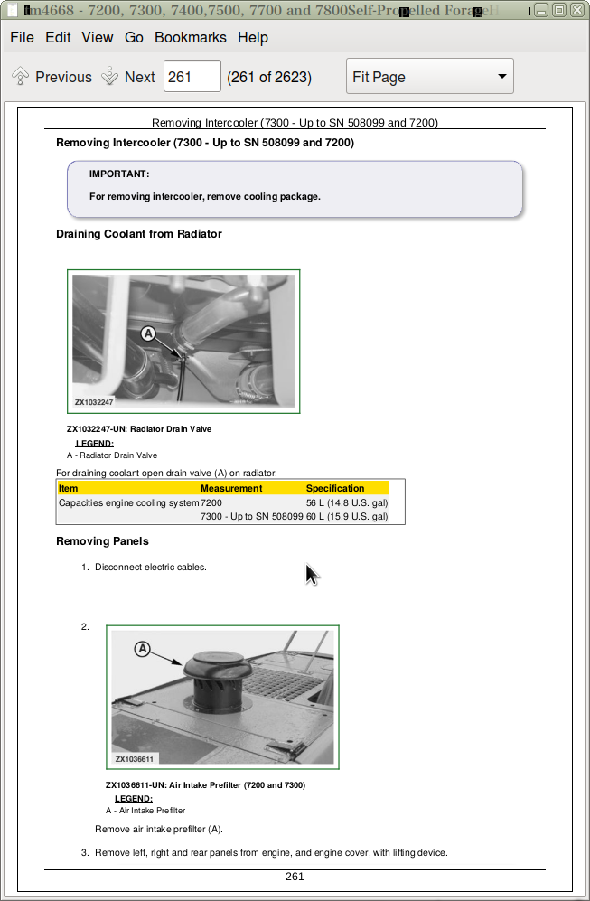
Removing Intercooler (7300 - Up to SN 508099 and 7200)
Removing Intercooler (7400, 7500, 7700 and 7800 - Up to SN 507478)
Removing Intercooler (7300 - From SN 508100 and 7400, 7500, 7700 and 7800 - From SN 507479)
Group 15: Cooling System
Specifications
Cooling Package Location
Replacing Coolant Level Sending Unit
Removing Radiator (7300 - Up to SN 508099 and 7200)
Removing Radiator (7400, 7500, 7700 and 7800) - Up to SN 507478
Removing Radiator (7300 - From SN 508100 and 7400, 7500, 7700 and 7800 - From SN 507479)
Removing Fuel Cooler (7400, 7500, 7700 and 7800)—Up to SN 507478
Removing Fuel Cooler (7800)—From SN 507479
Removing Hydraulic Oil Cooler (7300 - Up to SN 508099 and 7200)
Removing Hydraulic Oil Cooler (7400, 7500, 7700 and 7800)—Up to SN 507478
Removing Hydraulic Oil Cooler (7300 - From SN 508100 and 7400, 7500, 7700 and 7800 - From SN 507479)
Removing Transmission Oil Cooler (ProDrive Only)
Removing Air Conditioning Condenser (7300 - Up to SN 508099 and 7200)
Removing Air Conditioning Condenser (7400, 7500, 7700 and 7800)—Up to SN 507478
Removing Air Conditioning Condenser (7300 - From SN 508100 and 7400, 7500, 7700 and 7800 - From SN 507479)
Replacing the Viscous Drive
Checking Belt Tensioner Spring Tension and Belt Wear—Up to SN 507478
Checking Belt Tensioner Spring Tension and Belt Wear—From SN 507479
Rotary Screen
Section 40: Electrical System
Group 05: Harness and Connector Repair
Essential or Recommended Tools
Other Material
Use Electrical Insulating Compound
Using High-Pressure Washers
Repair WEATHER PACK Connector
Remove Connector Body from Blade Terminals
Repair (Pull Type) METRI-PACK METRI-PACK is a trademark of Delphi Packard Electric Systems Connectors
Repair (Push Type) METRI-PACK Connectors
Repair CPC CPC is a trademark of AMP Inc. , Large MATE-N-LOC MATE-N-LOC is a trademark of AMP Inc. and METRIMATE METRIMATE is a trademark of AMP Inc. Pin Type Connectors
Repair CPC Blade Type Connectors
Repair Small MATE-N-LOC Socket Connector
Repair Small MATE-N-LOC Pin Connector
Repair DEUTSCH Connectors
Repair CINCH Connectors
Repair Relay Panel Connectors
Repair Reel Reversing Valve Connector
Group 10: Electrical System Components
Specifications
Electrical System — Specifications
Batteries
Battery Switch
Dangers When Handling Batteries
Battery Service
Checking Electrolyte Level
Checking Specific Gravity
Charging Batteries
Installing and Connecting Batteries
Alternators—Up to SN 507478
Alternator—From SN 507479
Starter Motor
Sockets
Replacing Terminating Resistors
Control Units
Fuse / Relay Tester
Spare Fuses
Fuse and Relay Boards A1, A2 and A3
Extra Fuses and Relays
Engine Oil Pressure Sending Unit B1 / B45
Cutterhead Alarm, Front B2
Cutterhead Alarm, Back B3
Reverser Motor Pressure Switch B4
Lift Cylinder Pressure Transducer B5
Hydrostatic Oil Temperature Sending Unit B6
Hydraulic Oil Filter Sensor B7
Hydrostatic Charge Pressure Sending Unit B8
Air Cleaner Sending Unit B9
Cutterhead Speed Sending Unit B10 IVLOC
Cutterhead Speed Sending Unit B10 Four-Speed LOC
IVLOC Pressure Control Switch B11
Ground Speed Sending Unit B12 (Three-Speed Transmission)
IVLOC Hydraulic Pressure Switch B13
Front Wheel Speed Sending Units B14 / B68
Horn B15
Feedroll Speed Sending Unit B16 IVLOC
Feedroll Speed Sensor B16 Four-Speed LOC - Up to SN 506846
ATC Air Conditioning System Low Pressure Switch B17
ATC Air Conditioning System High Pressure Switch B18
Solar Sending Unit B19—Up to SN 507478
Rear-Wheel Drive Pressure Sending Unit B22
Rear-Wheel Drive Speed Sending Unit B23
Metal Detector Sending Unit B24
Transmission Oil Temperature Sending Unit B25 - Up to SN 507478
Knock Sending Unit B26 and B27
Fuel Tank Sending Unit B28
Reverse Travel Alarm B30
Coolant Temperature Sending Unit B31 / B43
Fuel Temperature Sending Unit B33
Intake Air Temperature Sending Unit B34
Engine Camshaft Sending Unit B35 / B44
Engine Crankshaft Sending Unit B36 / B40
Fuel Pressure Sending Unit B37 / B39
Water-In-Fuel Sending Unit B38 / B46
Intake Manifold Pressure and Temperature Sending Unit B41 (Cummins Engine)
Ambient Air Pressure Sending Unit B42 (Cummins Engine)
Stationary Knife Motor-Impulse Sending Units B47 and B48
Inlet Temperature Sending Unit B49
Outlet Temperature Sending Unit B50
Cab Temperature Sending Unit B51
Evaporator Core Temperature Sending Unit B52
Kernel Processor Motor-Impulse Sending Unit B53 and B54
Hydrostatic Pump Pressure Reverse Sending Unit B55
Feedroll Distance Sending Unit B58
Hydrostatic Pump Pressure Forward Sending Unit B59
Hi/Lo Transmission Pressure Sending Unit B61
Hi/Lo Transmission Temperature Sending Unit B62
Front Motor Speed Sending Unit B63
Multi-Function Lever Position Sending unit B64
Parking Brake Sending Unit B65
Transmission Speed Sending Unit B66
Rear Wheel Sending Unit B67 (Row Guidance Gen. 2)
Row Guidance Steering Input Sending Unit B69 (Row Guidance Gen. 2)
Alternators—Up to SN 507478
Alternator—From SN 507479
Remove and Install Alternators—Up to SN 507478
Remove and Install Alternator—From SN 507479
Rotary Radiator Screen Drive Motor M2
ATC Air Conditioning System Recirculating Blower Motor M3
Front Windshield Wiper Motor M4
Front Windshield Washer Pump M5
Spout Flap Motor M6
Kernel Processor Lift Motor M8
Knife Sharpening Motor M10
Stationary knife Adjusting Motors M11 and M12
Kernel Processor Adjusting Motors M13 and M14
Side Windshield Wiper Motors M15 and M16
Side Windshield Washer Pump M17
Sharpening Door Motor M18
ATC Air Conditioning System Pressurizer Blower Motor M20
Outside Mirror Motor M21 and M22
Stone Sweep Position Potentiometer R6
Sharpening Door Position Potentiometer R9
Rear Wheel Potentiometer R12 (Row Guidance Gen. 1)
Header Angle Potentiometer R17
Transmission 3rd Gear Switch S21
Manual Sharpening Door Switch S26
Kernel Processor Electric Lift Switch S28
Header Safety Switch S30
LOC Neutral Position Switches S32 and S33
Stop Light Switch S35
Row Guidance Pressure Switch S38 (Row Guidance Gen. 1)
Transmission Oil Pressure Switch S48
Battery Main Switch S51
Accumulator Charge Pressure Switch S52
Manual Cutterhead Reverse Switch S53
Reverse Drive Switch S54 (Three-Speed Transmission)
Parking Brake Switch S56 (Three-Speed Transmission)
Coolant Level Switch S57
Reed Switch S60 (676/678 RHU)
Rotary Screen Speed Sending Unit S67
Ether Starting Aid Y1
Automatic Header Control Shut Off Valve Y2
IVLOC Quick Stop Pawl Solenoid Y3
IVLOC Solenoids—Up to SN 507478
IVLOC Solenoids—From SN 507479
Proportional Valve Solenoids (Three-Speed Transmission)
Proportional Valve Solenoids (ProDrive Transmission)
ProDrive Transmission Solenoids
ATC Air Conditioning Clutch Y11
Main Hydraulic System Solenoids
IVLOC Proportional Valves Y18 and Y19
Gear Lock Solenoid Y20 (Three-Speed Transmission)
Wagon Dump High Flow Solenoids
Low Pressure Solenoids (Three-Speed Transmission)
Low Pressure Solenoids (ProDrive Transmission)
IVLOC Reversing Pawl Solenoid Y34
Four Speed LOC Reverser Motor Solenoid Y35
Row Guidance Solenoid Valves Y36 and Y37 (Row Guidance Gen. 1)
Four Speed LOC Electrical Clutch Y38
Four Speed LOC Pawl Solenoid Y39
Row Guidance Valve Block Y40 (Row Guidance Gen. 1)
Row Guidance Valve Block Y40 (Row Guidance Gen. 2)
Rear Wheel Drive Proportional Valve Y41
Fuel Pump Control Valves Y42 and Y43 (8.1L Engine)
Front Motor Proportional Valve Y45
Transmission Pump-Forward and Reverse Valves Y46 / Y47 (ProDrive Transmission)
Fuel Shutoff Solenoid Valve Y50 (Cummins Engine)
Wastegate Solenoids Y61 and Y62 (Cummins Engine)
Fuel Solenoids Y63, Y64, Y65 and Y66 (Cummins Engine)
Replacing Bulbs
Safety Rules When Replacing Halogen Bulbs
Safety Rules When Replacing Xenon Bulbs
Cab Head Light Bulb Replacement and Adjustment - Up to SN 508099
Cab Head Light Bulb Replacement and Adjustment - From SN 508100
HID-Xenon Bulb Replacement and Adjustment
Turn Signal Indicator Light Bulb Replacement
Dome and Console Light Bulb Replacement
Automatic Function Control Panel Light Bulb Replacement
Moisture Sensor Adapter Glass Replacement
Observe Electrical Precautions
Basic Electrical Component Handling / Precautions For Vehicles Equipped With Computer Controlled Systems
Section 50: Power Train
Group 05: Main Drive Belt Replacement
Specifications
Replace Main Drive Belt
Group 10: Bevel Gear Drive
Specifications
Other Material
Essential or Recommended Tools
Special Tool (Self-Manufactured)
Modify Assembly Fixture (KJD10350)
Other Material
Remove Bevel Gear Drive
Attaching Bevel Gear Drive to Assembly Fixture
Main Clutch Assembly
Check Main Clutch
Remove Clutch
Hub Components
Bevel Gear Drive Disassembly
Bevel Gear Drive Assembly
Determination of Adjusting Measure for Drive Pinion
Dimension “C”
Dimension “H”
Dimension “G”
Dimension “B”
Drive Shaft Reassembly
Determination of Adjusting Measure for Output Pinion
Dimension “D”
Dimension “F”
Dimension “E”
Dimension “A”
Output Shaft Reassembly
Output Shaft Adjustment
Install Output Shaft
Disk Clutch Reassembly
Install Clutch Oil Jet fitting
Install Bevel Gear Drive
Group 15: Transmission and Differential (Three-Speed Transmission)
Specifications
Other Material
Drain Oil
Remove and Repair Shifter Forks and Shifter Cam
Install Shifter Forks and Shifter Cam
Remove and Install Transmission Lube Pump
Remove and Install Suction Screen
Remove Transmission
Transmission Components
Transmission Recondition
Disassemble and Repair Transmission
Remove Pinion Shaft
Remove Differential
Disassemble Differential
Assemble Differential
Assemble Transmission
Install Transmission
Remove and Install Gearshift Lever and Linkage
Adjusting Gearshift Linkage
Group 16: Transmission and Differential (ProDrive Transmission)
Specifications
Essential or Recommended Tools
Special Tools—Dealer Fabricated
Other Material
Draining Oil
Remove and Install Shift Valve Housing
Remove and Repair Valves from Shift Valve Housing
Shift Valve Housing-Exploded View
Install Valves in the Shift Valve Housing
Remove Transmission
Transmission Components-Overview
Disassemble Transmission
Remove Brake Modules
Disassemble Brake Modules
Brake Modules-Exploded View
Assemble Brake Modules
Install Brake Modules
Remove Differential Module
Disassemble Differential Module (With Differential Lock)
Differential (With Differential Lock)-Exploded View
Assemble Differential Module (With Differential Lock)
Install Differential Module
Remove Gear-Shift Planetary Drive With Clutch (Forward/Reverse)
Disassemble Gear-Shift Planetary Drive With Clutch (Forward/Reverse)
Gear-Shift Planetary Drive With Clutch (Forward/Reverse)-Exploded View
Assemble Gear-Shift Planetary Drive With Clutch (Forward/Reverse)
Install Gear-Shift Planetary Drive With Clutch (Forward/Reverse)
Remove Countershaft
Repair Countershaft
Countershaft-Exploded View
Install Countershaft
Assemble Transmission
Install Transmission
Group 20: Final Drives
Specifications
Essential or Recommended Tools
Service Equipment and Tools
Other Material
Remove Final Drive
Disassemble and Assemble Final Drive
Adjust Spindle Bearing (Preferred Method)
Adjust Spindle Bearing (Alternative Method)
Install Final Drive
Final Drive Attaching Screws
Group 25: Hydrostatic Drive, Variable Pump (Three-Speed Transmission)
Specifications
Essential or Recommended Tools
Service Equipment and Tools
Other Material
Serial Number Plate
Clean Variable Pump
Flushing the Hydrostatic System
Remove Variable Pump
Remove Variable Pump (Machines with IVLOC)
Remove Variable Pump (Machines with Four- Speed LOC)
Disassemble Variable Pump
Assemble Variable Pump
Disassemble and Assemble End Cover
Repair Control Valve
Repair Charge Pump
Install Variable Pump
Remove and Install Hydrostatic Control Cable
Adjust Hydrostatic Neutral Linkage
Adjust Displacement Control Valve Neutral
Group 26: Hydrostatic Drive, Variable Pump (ProDrive Transmission)
Essential or Recommended Tools
Special Tool (Self-Manufactured)
Specifications
General View
Serial Number Plate
Clean Variable Pump
Remove Variable Pump
Sealing the Drive Shaft
Sealing the Boost Pump
Sealing the Control Piston Cover
Sealing The Boost Pressure Valve
Sealing the Pressure Cut Off Valve
Remove Control Unit
Disassembling the Pump
Disassembling Cylinder Assembly
Disassembling the Control Piston
Inspection Notes
Assembling the Pump
Installing the Rotary Group
Adjustment Instructions
Group 30: Hydrostatic Drive, Fixed-Displacement Motor (3-Speed Transm.)
Specifications
Clean Fixed-Displacement Motor
Remove Fixed-Displacement Motor
Disassemble Fixed-Displacement Motor
Inspect Parts
Lack of Lubrication
Abrasive Contamination
Cavitation
Over Speeding
Inspect Shaft Seal
Inspect Thrust Plate
Inspect Fixed Swashplate
Inspect Piston Slipper
Inspect Piston Retainer
Inspect Cylinder Block
Inspect Bearing Plate
Inspect Valve Plate
Inspect Bearing and Race
Inspect Servo Piston
Inspect Drive Shaft
Replace Cylinder Block Spring
Assemble Motor
Install Fixed-Displacement Motor
Remove and Install Motor Valve Block (Manifold)
Repair Motor Valve Block
Group 31: Hydrostatic Drive, Variable-Displacement Motor (ProDrive)
Specifications
Remove Variable-Displacement Motor
General View
Sealing the Cover Plate
Sealing of the Control Parts
Disassembling the Port Plate
Assembling the Port Plate
Disassembling the Rotary Group
Inspection Notes
Assembling the Rotary Group
Rotary Group Adjustment
Group 40: Rear Wheel Drive Axle—107 cc Motor Type
Specifications
Essential Tools
Other Material
Remove Axle Housing From Machine
General Description
Sealing Compounds and Adhesives
Dimensions
Oil Change and Checks
Tightening Torques Overview
Disassembling the Steering Cylinder
Assembling the Steering Cylinder
Disassembling the Reduction Gear
Assembling the Reduction Gear
Disassembling the Wheel Hub
Assembling the Wheel Hub
Disassembling the Axle Housing
Assembling the Axle Housing
Disassembling the Differential Support
Assembling the Differential Support
Disassembling the Differential
Assembling the Differential
Disassembling the Pinion
Assembling the Pinion
Disassembling the Flange
Assembling the Flange
Toe-in Adjustment
Steering Angle Adjustment with Goniometer
Steering Angle Adjustment with Steering Stops
Testing after Assembling
Group 41: Rear Wheel Drive Axle—140 cc Motor Type
Specifications
Essential Tools
Other Material
Changing Oil
Remove Axle Housing From Machine
Replacing Pivot Pin Bushings
Disassemble the Planetary Drive
Planetary Drive—Exploded View
Assemble the Planetary Drive
Disassemble the Swivel Housing
Swivel Housing—Exploded View
Assemble the Swivel Housing
Disassemble the Differential
Differential—Exploded View
Assemble the Differential
Disassemble the Steering Cylinder
Steering Cylinder—Exploded View
Assemble the Steering Cylinder
Adjusting Tread
Fender and Fender Support Removal and Installation (ProDrive Transmission)
Group 45: Rear Wheel Drive Axle, Variable-Displacement Motor
Essential or Recommended Tools
Specifications
General View
Sealing the Cover Plate
Sealing of the Control Parts
Disassemble the Port Plate
Assembling the Port Plate
Disassembling the Rotary Group
Inspection Notes
Assembling the Rotary Group
Rotary Group Adjustment
Section 60: Brakes, Steering and Rear Axle
Group 05: Brake Operation (Three-Speed Transmission)
Essential or Recommended Tools
Other Material
Specifications
Remove and Install Master Cylinder
Disassemble and Assemble Master Cylinder (Double Bleed Screw)
Brake Fluid Reservoir
Adjusting Master Cylinder
Bleeding Brake System—Double Bleed Screw
Remove and Install Slave Cylinders
Disassemble and Assemble Slave Cylinders
Disassemble and Assemble Brake Pedals
Disassemble and Assemble Parking Brake Pedal
Adjust Park Brake Pedal
Group 06: Brake Operation (ProDrive Transmission)
Other Material
Specifications
Remove and Install Master Cylinder
Disassemble and Assemble Master Cylinder
Adjusting Master Cylinder
Bleed Service Brakes
Disassemble and Assemble Brake Pedals
Disassemble and Assemble Parking Brake Valve (Accumulator Charge)
Group 10: Brakes (Three-Speed Transmission)
Service Equipment and Tools
Other Material
Specifications
Deglazing Brake Linings
Remove Brake Drum
Remove Brake Shoe
Repair Brakes
Brake Assembly
Group 11: Brakes (ProDrive Transmission)
Essential or Recommended Tools
Other Material
Specifications
Check Brake Disk Thickness
Repair Brake Disks
Group 15: Hydrostatic Steering
Essential or Recommended Tools
Other Material
Specifications
Steering Hydraulics (IVLOC - Three-Speed Transmission)
Steering Hydraulics (IVLOC - ProDrive Transmission)
Steering Hydraulics (Four-Speed LOC)
Removing the Steering Valve
Steering Valve Components
Disassembling the Steering Unit
Removing Safety Valves
Removing Check Valve
Removing Spool and Sleeve
Disassembling the Spool Assembly
Removing Leaf Springs
Removing Seal Ring
Removing the Safety Valves
Removing Pressure-Control Valve
Repairing the Steering Unit
Assembling the Steering Unit
Installing Pressure-Control Valve
Installing Safety Valves
Arranging the Leaf Springs
Installing the Leaf Springs
Assembling the Spool Assembly
Installing Retaining Ring and Cross Pin
Assembling the Thrust Bearing
Installing the Seal Ring
Installing O-Ring and Back-Up Ring
Installing Spool Assembly
Installing the Check Valve
Installing Safety Valves
Installing the O-Ring
Installing Distributor Plate and Drive Shaft
Installing Rotor and Stator
Installing Spacer Ring
Installing Metering Unit Cover
Safety Valve Test
Adjusting the Safety Valves
Pressure Control Valve Test
Adjusting the Pressure-Control Valve
Install Steering Valve
Bleeding the Hydrostatic Steering System
Steering Column Components
Disassemble And Assemble Steering Column
Replace Telescoping Shaft Bearings
Hydraulic Lines to Steering Cylinders- Adjustable and Standard Rear Axle
Steering Cylinder With Ball Joints- Adjustable and Standard Rear Axle
Remove and Install Steering Cylinder- Adjustable and Standard Rear Axle
Repair Steering Cylinder- Adjustable and Standard Rear Axle
Tie Rod — Exploded View - Adjustable and Standard Rear Axle
Adjusting Toe-In - Adjustable and Standard Rear Axle
Checking Rear Wheel Toe-In - Adjustable and Standard Rear Axle
Group 16: Row Guidance System (Gen. 1)
Specifications
Row Guidance System Components
Checking and Adjusting Linear Potentiometer - Adjustable and Standard Rear Axle
Checking and Adjusting Rotary Potentiometer - Four Wheel Drive Rear Axle—107 cc Motor Type
Calibrating Control Unit
Address RGC 101 Calibration — Ratio Setting
Address RGC 102 Calibration — Filter Setting
Address RGC 106 Calibration — Feeler Rest Position
Address RGC 107 Calibration — Feeler Maximum Deflect Position
Address RGC 104 Calibration — Steering Offset
Address RGC 105 Calibration — Bias Calibration
Address RGC 108 Calibration — Steering Test Mode
Address RGC 109 Calibration — Feeler Side Swap
Group 17: Row Guidance System (Gen. 2)
Specifications
Other Material
Row Guidance System Components
Checking Rotary Potentiometer - Old Assembly
Checking Rotary Potentiometer - New Assembly
Removing and Installing Steering Valve Block and Steering Input Sending Unit
Calibrating Control Unit
Address RGC 100 Calibration — Sensitivity (GEN. 2)
Address RGC 101 Calibration — Feelers (GEN.2)
Address RGC 102 Calibration — Wheel Angle Sensor/Steering Wheel Position Sensor (GEN. 2)
Address RGC 105 Calibration — Steering Valve Deadband (GEN. 2)
Address RGC 108 Calibration — Steering Test Mode (GEN. 2)
Address RGC 109 Calibration — Feeler Side Swap
Group 20: Rear Axle
Essential or Recommended Tools
Other Material
Specifications
Rear Axle Spindle Components - Adjustable and Standard Rear Axle
Remove and Install Rear Spindle Assembly - Adjustable and Standard Rear Axle
Wheel Hub Exploded View
Adjusting Rear Axle Width
Rear Axle Pivot Bushing - Four Wheel Drive Rear Axle—107 and 140 cc Motor Type
Rear Axle Pivot Bushing - Adjustable and Standard Rear Axle
Remove and Install Rear Axle Pivot Bushing
Section 70: Hydraulic System
Group 05: Hydraulic Pressure Accumulators
Specifications
Essential or Recommended Tools
General Repair Information
Accumulators
Harvesting Unit Float System (IVLOC - Three-Speed Transmission)
Harvesting Unit Float System (IVLOC - ProDrive Transmission)
Harvesting Unit Float System (Four-Speed LOC)
Main Clutch System (Three-Speed Transmission)
Main Clutch System (ProDrive Transmission)
Discharge Spout System
Checking Accumulators
Recharging Accumulators
Lowering Accumulator Pressure
Group 10: Hydraulic Pumps
Specifications
Other Material
General Repair Information
Draining Hydraulic Oil
Pressure And Temperature Sending Units At Hydraulic Oil Tank
Refilling Hydraulic Oil
Repair Information
Removing Hydraulic Pumps
Marking Hydraulic Pumps
Disassemble Hydraulic Pumps
Replace Shaft Seal
Installing Gasket and Support
Hydraulic Pumps, Exploded View
Assembling Hydraulic Pumps
Install Hydraulic Pumps
Group 15: Electromagnetic Control Valve
Solenoid Valves - Main Block
Hydraulic Valve Assembly - Main Block
Remove Solenoid Main Valve Block
Repair Unload Valve (Y30)
Solenoid Valves, Discharge Spout Rotation (Y12 and Y13)
Solenoid Valves for Raising-Lowering Discharge Spout (Y15, Y14) and Header Folding (Y23, Y24)
Solenoid Valves, Low Flow (Y25 and Y26)
Solenoid Valves, Trailer (Y31 and Y32)
Repair Reverser Solenoid Valve (Y35), Four-Speed LOC
Solenoids, Low Pressure Valve Block
Remove Low Pressure Valve Block
Repair Low Pressure Valve Block (ProDrive Transmission)
Solenoids, Wagon Dump Valve Block
Remove Wagon Dump Valve Block
Repair Wagon Dump Valve Block
Group 20: Reverser Motor (Four-Speed LOC)
Removing Reverser Motor
Disassembling Reverser Motor
Repairing Reverser Motor
Group 25: Hydraulic Motor — Discharge Spout
Specifications
Removing Hydraulic Motor
Disassembling Hydraulic Motor
Hydraulic Motor, Exploded View
Repairing Hydraulic Motor
Assembling Hydraulic Motor
Group 30: IV Length-of-Cut Transmission Motor
Essential or Recommended Tools
Specifications
General Description
Remove/Install Motor
Replacing the Drive Shaft Seal
Remove the Connection Plate
Installing The Connection Plate
Disassemble the Flushing Valve
Assembling The Flushing Valve
Disassembling Motor
Inspecting Parts
Assemble the Motor
Adjusting Taper Roller Bearing Pre-Load
Group 35: IV Length-of-Cut Transmission Hydrostatic Pump
Essential or Recommended Tools
Specifications
General Description
Sealing the Drive Shaft
Sealing the Boost Pump
Sealing the Control Piston Cover
Sealing the Valves
Sealing the Pressure Cut Off Valve
Remove the Control Unit
Disassembling the Pump
Inspection Notes
Assemble the Pump
Installing the Rotary Group
Installing the Control Plate
Adjustment Instructions
Section 80: Miscellaneous
Group 05: Central Lubrication System
Specifications
Location of Primary and Secondary Distributors
Flow Schematic - Up to SN 508099
Flow Schematic - From SN 508100
Central Lubrication System—Up to SN 506846
Operational Information—Up to SN 506846
Automatic Lubrication System—From SN 506847
Operational Information—From SN 506847
Adjust Pump Element for Flow Control
Quick Couplers for Kernel Processor and Harvesting Unit
Troubleshooting - Central/Automatic Lubrication System
Section 90: Operator's Cab, Air Conditioning System
Group 05: Control Levers
Multi-Function Lever (Three-Speed Transmission)
Multi-Function Lever (ProDrive Transmission)
Group 10: Cab Ventilation
Specifications
Air Conditioning System With Precleaner (General Information)
Remove and Install Receiver/Drier
Replace Blower Motor
Replace Recirculator Motor Drive Module
Replace Heater Control Valve
Removing Air Conditioning Condenser (7300 - Up to SN 508099 and 7200)
Removing Air Conditioning Condenser (7400, 7500, 7700 and 7800)—Up to SN 507478
Removing Air Conditioning Condenser (7300 - From SN 508100 and 7400, 7500, 7700 and 7800 - From SN 507479)
Repair Condenser
Replace Evaporator
Remove and Install Evaporator Temperature Sensor
Replace Low Pressure Switch
Replace High Pressure Switch
Replace Air Temperature Sensors
Group 15: Operator's Cab
Specifications
Remove and Install Cab Windshield - Up to SN 508099
Remove and Install Cab Roof - Up to SN 508099
Remove and Install Cab Roof - From SN 508100
Cab Door Latch Striker
Remove and Install Cab Door
Disassemble and Assemble Cab Door
Rear Window Installation
Right-Hand Cab Window
Remove Cab
Install Cab
Group 20: R134a Air Conditioning System
Specifications
General Information
Essential or Recommended Tools
Service Equipment and Tools
Other Material
Safety at Work
Handling Refrigerant
Refrigerant Splashes into Eyes
Safety Equipment
Storage of Refrigerant Containers
R134a Refrigerant
Test and Service Ports—Up to SN 507478
Test and Service Ports—From SN 507479
Discharge Air Conditioning Refrigerant
Remove and Install Compressor—Up to SN 507478
Remove and Install Compressor—From SN 507479
Test Volumetric Efficiency
Test Shaft Seal Leakage
Disassemble and Assemble Compressor Clutch
Check Clutch Hub Clearance
Inspect Compressor Manifold
Disassemble, Inspect, and Assemble Compressor
Remove and Install Compressor Relief Valve
System Information
Flush Air Conditioning System
Purge Air Conditioning System
Evacuate Air Conditioning System
Compressor Oil Information
Determine Correct Oil Charge
Check Refrigerant Oil Charge
Charge Air Conditioning System
Leak Testing Procedure
Group 25: Super Comfort Seat
Specifications
Remove and Install Operator’s Seat
Remove and Install Operator Presence Switch
Operator's Seat Exploded View
Operator's Seat Air Suspension Assembly—Exploded View
Disassemble and Assemble Operator's Seat Air Suspension Assembly
Section 99: Special Tools
Group 05: Special Tools (Dealer Fabricated)
Self-Manufactured Tool for Bevel Gear Drive Repair
Self-Manufactured Tool for ProDrive Transmission Repair
Self-Manufactured Tool for Hydrostatic Drive Pump Repair—ProDrive Transmission
Group 10: Special Tools (Available as Spare Parts)
Essential or Recommended Tools
Essential Tools for Engine Repair
Essential Tools for Electrical System Repair
Essential Tools for Bevel Gear Drive Repair
Essential Tools for ProDrive Transmission Repair
Essential Tools for Final Drive Repair
Essential Tools for Hydrostatic Drive Pump Repair—Three-Speed Transmission
Essential Tools for Hydrostatic Drive Pump Repair—ProDrive Transmission
Essential Tools for Rear Wheel Drive Axle Repair—107 cc Motor Type
Essential Tools for Rear Wheel Drive Axle Repair—140 cc Motor Type
Essential Tools for Rear Wheel Drive Motor Repair
Essential Tools for Brake System Repair—Three-Speed Transmission
Essential Tools for Brake System Repair—ProDrive Transmission
Essential Tools for Steering System Repair
Essential Tools for Rear Axle Repair
Essential Tools for Hydraulic Pressure Accumulator Repair
Essential Tools for IV Length-of-Cut Transmission Motor Repair
Essential Tools for IV Length-of-Cut Transmission Hydrostatic Pump Repair
Essential Tools for Air Conditioning System Repair
Essential Tools for IV Length-of-Cut Transmission Repair
Essential Tools for Cutterhead Repair
Essential Tools for Blower Repair
Section 100: Harvesting Units
Group 05: Harvesting Unit Cross Drive
Specifications
Other Material
Harvesting Unit Cross Drive
Harvesting Unit Drive Exploded View—Four-Speed LOC Transmission
Harvesting Unit Drive Exploded View—IVLOC Transmission
Drive Assembly—Four-Speed LOC Transmission
Drive Assembly—IVLOC Transmission
Group 10: Harvesting Units
Pickup Units
Row-Crop Units
Rotary Harvesting Units (Row-Independent)
Corn Heads
Section 110: Feeding System
Group 05: Four Speed Length-Of-Cut Transmission
Specifications
Other Material
General Information
Remove Length-of-Cut Transmission From Machine
Disassemble Length-of-Cut Transmission
Transmission Case Shaft AZ Overview
Transmission Case Shaft BZ Overview
Transmission Case Shaft CZ Overview
Transmission Case Shaft DZ Overview
Transmission Case Shaft EZ Overview
Transmission Case Shaft FZ Overview
Transmission Case Shaft GZ Overview
Transmission Case Shaft HZ Overview
Assemble Length-Of-Cut Transmission
Chain Drive Exploded View
Installing Length-of-Cut Transmission
Group 10: IV Length-Of-Cut Transmission
Essential Tools
Specifications
Other Material
General Information
Remove Cut Out Clutch assembly
Disassemble/Assemble Cut Out Clutch
Install Cut Out Clutch Assembly
Remove/Disassemble Length-Of-Cut Transmission Brake With Transmission Case on Machine
Assemble/Install Length-Of-Cut Transmission Brake With Transmission Case on Machine
Remove/Disassemble Length-Of-Cut Transmission Feedroll Drive Gear Case With Transmission Case on Machine
Install/Assemble Length-Of-Cut Transmission Feedroll Drive Gear Case With Transmission Case on Machine
Remove Length-Of-Cut Transmission From Machine
Disassemble Length-Of-Cut Transmission
Disassemble/Assemble Length-Of-Cut Transmission Brake
Disassemble/Assemble Length-Of-Cut Transmission Main Clutch
Hydraulic Block Overview on 7200, 7300, 7400 and 7500—Up to SN 507478
Hydraulic Block Overview on 7700, 7800 and Forage Harvesters 7200, 7300, 7400 and 7500—From SN 507479
Modulating Valve Overview
Shaft AZ Overview
Shaft CZ Overview
Shaft EZ Overview
Shaft FZ Overview
Shaft GZ Overview
Shaft GPL Overview—Part 1
Shaft GPL Overview—Part 2
Shaft HZ Overview—Part 1
Shaft HZ Overview—Part 2
Shaft HYZ Overview
Assemble Length-Of-Cut Transmission
Install Length-Of-Cut Transmission On Machine
Group 15: Reverser Motor and Clutch (4-Speed L.O.C)
Specifications
Other Material
Reverser Motor and Clutch Exploded View
Reverser Clutch Assembly
Install Reverser Motor with Clutch
Group 20: Electrical Clutch (4-Speed L.O.C)
Specifications
Other Material
Electrical Clutch Exploded View
Electrical Clutch Assembly
Group 25: Feed Roll Channel
Open Feed Roll Housing
Close Feed Roll Housing
Feed Roll Housing Safety Switch (S30)
Group 30: Feed Roll Assembly
Specifications
Other Material
Disassemble/Assemble Feed Roll Gear Transmission
Disassemble/Assemble Feed Roll Assembly
Remove Rear Lower Feed Roll (Smooth Roll)
Install Rear Lower Feed Roll (Smooth Roll)
Replace Feed Roll Wear Plates and Stops
Lateral Guides for Upper Feed Rolls
Group 35: Locking Pawl (4-Speed L.O.C)
Specifications
Safety Measures
Adjusting Locking Pawl
Checking Adjustment
Section 120: Cutterhead Assembly
Group 05: Knife Sharpening Device
Specifications
Other Material
Knife Sharpening Device Removal
Knife Sharpening Device Repair
Knife Sharpening Device Cable Guide Exploded View
Sharpening Stone Block Cable Exploded View
Retensioning Guide Cable
Sharpening Stone Block Exploded View
Assemble Sharpening Stone Block
Sharpening Stone Replacement
Sharpening Stone Alignment
Group 10: Cutterhead
Essential or Recommended Tools
Specifications
Other Material
Replace Cutterhead and Knife Attaching Parts
Knife Screw Torque
Removing Cutterhead Assembly From Machine
Cutterhead Removal
Cutterhead—Exploded View
R.H. Side Cutterhead Bearing—Repair
L.H. Side Cutterhead Bearing—Repair
Cutterhead Installation
Installing Cutterhead Assembly on Machine
Group 15: Bottom and Outlet Bands
Specifications
Cutterhead Bottom and Outlet Bands
Bottom Band Adjustment
Outlet Band Adjustment
Recirculating Screens
Install/Change Recirculating Screen
Recirculating Screen Adjustment
Bottom and Outlet Band Removal
Install Spiral/Recutter Floor
Spiral/Recutter Floor Adjustment
Adjust the Service Cover on the Transition Chute
Group 20: Stationary Knife Removal and Installation
Specifications
Stationary Knife Removal
Remove Stationary Knife Adjusting Device
Install Stationary Knife
Torque at Stationary Knife Adjusting Device
Eliminate End Play of Adjusting Spindle
Group 25: Kernel Processor
Specifications
Other Material
Kernel Processor Main Drive Locking Device (Four-Speed LOC Only)
Replace Drive Belts of Lower Roll
Kernel Processor Quick Removal
Adjust the Feed Plate On the Kernel Processor
Kernel Processor Drive Exploded View (Three-Speed Transmission)
Kernel Processor Drive Exploded View (ProDrive Transmission)
Grooved Roll Removal
Kernel Processor Housing Exploded View
Upper Grooved (Drive) Roll Exploded View—Up To SN 508668
Upper Grooved (Drive) Roll Exploded View—From SN 505669
Lower Grooved (Driven) Roll Exploded View—Up To SN 508668
Lower Grooved (Driven) Roll Exploded View—From SN 508669
Grooved Roll Adjusting Device, Exploded View
Electrical Adjusting Device, Exploded View
Idler and Deflector Pulleys, Exploded View
Idler Pulley Repair
Grooved Roll Installation—Up To SN 508668
Grooved Roll Installation—From SN 508669
Adjust Roll Clearance (Manual Adjustment)—Up To SN 507478
Adjust Roll Clearance (Manual Adjustment)—From SN 507479
Automatic Adjustment of Grooved Rolls
Adjust Scrapers
Pretension of Lower Roll Drive Belt
Group 30: Power Chute
Specifications
Power Chute Main Drive Locking Device (Four-Speed LOC Only)
Install the Power Chute on the Kernel Processor
Install the Power Chute on the Attaching Frame
Adjust the Feed Plate On the Power Chute
Power Chute Exploded View
Power Chute Repair
Power Chute Removal
Drive Belts
Section 130: Discharge Components
Group 05: Discharge Fan
Specifications
Discharge Fan Exploded View
Replace Wear Plate
Install Wear Plate
Replace and Adjust Blower Paddles- General
Adjust Blower Paddles
Adjust Deflecting Edges
Group 10: Blower Rotor and Rotor Bearings
Specifications
Essential or Recommended Tools
Remove/Install Blower Rotor Drive Pulley
Remove/Install Blower Rotor Self-Aligning Bearings
Remove Blower Rotor
Blower Rotor Exploded View
Install Blower Rotor
Group 15: Discharge Spout
Specifications
Spout Turning Device Exploded View
Install Spout Turning Device
Install Spout Worm Gear
Spout Exploded View—High Arc
Spout Exploded View—Low Arc
John Deere Self-Propelled Forage Harvesters Models 7200, 7300, 7400, 7500, 7700, 7800, 7900 Repair Service Manual (TM4668)
![]()