
John Deere Self-Propelled Forage Harvesters Models 8100, 8200, 8300, 8400, 8500, 8600, 8700, 8800 (Worldwide Edition) Diagnosis & Tests Service Technical Manual (TM407019)
Complete Diagnostic and Tests service manual with Electrical Wiring Diagrams for John Deere 8100, 8200, 8300, 8400, 8500, 8600, 8700, 8800 Forage Harvester (Worldwide Edition), with workshop information to maintain, diagnose, and rebuild like professional mechanics.
John Deere Self-Propelled Forage Harvesters Models 8100, 8200, 8300, 8400, 8500, 8600, 8700 & 8800 workshop operation & tests manual includes:
* Numbered table of contents easy to use so that you can find the information you need fast.
* Detailed sub-steps expand on repair procedure information
* Numbered instructions guide you through every repair procedure step by step.
* Troubleshooting and electrical service procedures are combined with detailed wiring diagrams for ease of use.
* Notes, cautions and warnings throughout each chapter pinpoint critical information.
* Bold figure number help you quickly match illustrations with instructions.
* Detailed illustrations, drawings and photos guide you through every procedure.
* Enlarged inset helps you identify and examine parts in detail.
TM407019 - John Deere Self-Propelled Forage Harvesters Models 8100, 8200, 8300, 8400, 8500, 8600, 8700, 8800 (Worldwide Edition) Technical Manual (Diagnosis & Tests).PDF
TM407019 - John Deere Self-Propelled Forage Harvesters Models 8100, 8200, 8300, 8400, 8500, 8600, 8700, 8800 (Worldwide Edition) Technical Manual (Diagnosis & Tests).EPUB
Total Pages: 11,081 pages
File Format: PDF/EPUB/MOBI/AZW (PC/Mac/Android/Kindle/iPhone/iPad; bookmarked, ToC, Searchable, Printable)
Language: English
MAIN SECTIONS
Diagnostic trouble codes
ATC Control Software
CAB Control Software
CHC Control Software
CRU Control Software
CSM Control Software
ECU Control Software
FH1 Control Software
FH2 Control Software
ITC Control Software
HM1 Control Software
JDL Control Software
MHC Control Software
PDU Control Software
PTP Control Software
UIC Control Software
XMC Control Software
XSC Control Software
Engine - Component Information
Engine
Fuel, Air Intake, Cooling and Aftertreatment Systems
Fuel, Air Intake, Cooling and Aftertreatment Systems - Component Information
Electrical System
General Information
Power Supply and Ground Points
Bus Systems
Interface between Forage Harvester and Engine
Transmission
Cutterhead Assembly
Knife Sharpening Function
Miscellaneous Systems
Kernel Processor
Miscellaneous Sensor Applications
Summary of Ground Points
Electronic Cab Systems
HVAC
AMS Systems
Automatic Header Positioning
Dual Header Drive
SCV1 / SCV2 / Wagon Dump
Lights and Signals
Spout Control
Electronic Cab Systems
Transmission
Interface between Forage Harvester and Engine
Cutterhead Assembly
Automatic Header Positioning
Knife Sharpening Function
Miscellaneous Systems
Miscellaneous Sensor Applications
Kernel Processor Control
Control Units
Electrical Connectors, Wiring Harnesses, and Components
- Sensors
- Assemblies
- Diodes
- Miscellaneous Devices and Equipment
- Protective Equipment
- Power Supply and Generator
- Monitoring and Signaling Devices
- Relays
- Engines
- Wiring Harnesses
- Resistors
- Switches
- Connectors to External Systems
- Ground Points
- Power Outlets and Diagnostic Connectors
- Valves
- Connection Points on Harnesses
ProDrive Transmission
3-Speed Push Button Shift Transmission (PBST)
Feedroll Drive
Header Drive
Steering and Brakes
Rear Axle
Hydraulic System
Hydraulic Functions
Low Pressure Hydraulic System
Headers
Hydraulic System Components
- Additive Dosing System
- Component Information
- Central Lubrication System
- Air Compressor
Operator`s Cab
Special Tools
Operator`s Cab Components
tm407019 - 8100, 8200, 8300, 8400, 8500, 8600, 8700 and 8800 Self-Propelled Forage Harvesters - Diagnostics -: (Worldwide Edition)
Table of Contents
Foreword
Version Date
Section 210: General Information
Group 05A: Safety
General Information - Safety, Summary of References
Recognize Safety Information
Understand Signal Words
“Important” Information
“Note” Information
Replace Safety Signs
Live With Safety
Deliver Safely
Use a Safety Chain
Passenger Seat
Use Seat Belt Properly
Read Operator Manuals for ISOBUS Implements
Use Steps and Handholds Correctly
Avoid Contact with Agricultural Chemicals
Prevent Machine Runaway
Prevent Machine Runaway
Avoid Hot Exhaust
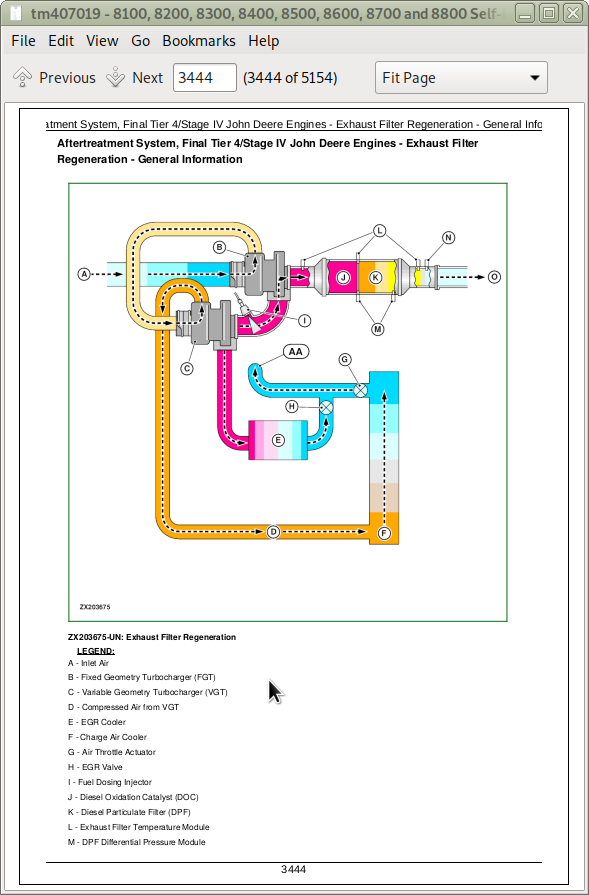
Exhaust Filter Cleaning
Clean Exhaust Filter Safely
Handle Fuel Safely—Avoid Fires
Handle Starting Fluid Safely
Prevent Battery Explosions
Prevent Acid Burns
Prepare for Emergencies
Use Safety Lights and Devices
Avoid High-Pressure Fluids
Protect Against High Pressure Spray
Service Accumulator Systems Safely
Wait Before Opening High-Pressure Fuel System
Service Cooling System Safely
Remove Paint Before Welding or Heating
Avoid Heating Near Pressurized Fluid Lines
Work In Ventilated Area
Wear Protective Clothing
Protect Against Noise
Service Machines Safely
Practice Safe Maintenance
Park Machine Safely
Use Proper Lifting Equipment
Install All Guards
Stay Clear of Rotating Drivelines
Construct Dealer-Made Tools Safely
Support Machine Properly
Work in Clean Area
Illuminate Work Area Safely
Use Proper Tools
Service Tires Safely
Park Forage Harvester
Avoid Backover Accidents
Dispose of Waste Properly
Safety Measures on Electronic Control Units
Servicing Electronic Control Units
Welding Near Electronic Control Units
Keep Electronic Control Unit Connectors Clean
Group 05B: General References
General References - Summary of References
Trademarks
Unified Inch Bolt and Screw Torque Values
Metric Bolt and Screw Torque Values
Term Definitions
Group 05C: Technical References
Technical References - Summary of References
Serial Numbers
Forage Harvester - Serial Number Plate (Product Identification)
Product Identification Number
Engine - Serial Number (PowerTech™ PSS 6090 FT4)
Engine - Serial Number (PowerTech™ Plus 6090 T3)
Engine - Serial Number (PowerTech™ 6090 T2)
Engine - Serial Number (PowerTech™ PSS 6135 FT4)
Engine - Serial Number (PowerTech™ Plus 6135 T3)
Engine - Serial Number (PowerTech™ 6135 T2)
Engine - Serial Number Cummins QSK19 (T2)
Exhaust Filter - Serial Number
SCR Catalyst - Serial Number
Operator's Cab Serial Number
Distribution Gear - Serial Number
ProDrive™ Transmission - Serial Number
ProDrive™ Hydrostatic Pump - Serial Number
ProDrive™ Hydrostatic Motor - Serial Number
3-Speed Push Button Shift Transmission - Serial Number
Hydrostatic Pump, 3-Speed Push Button Shift Transmission - Serial Number
Hydrostatic Motor, 3-Speed Push Button Shift Transmission - Serial Number
Hydraulic Pump of the Hydraulic System with LS Control - Serial Number
Upper Feedroll Drive - Serial Number
Lower Feedroll Drive - Serial Number
Hydrostatic Pump, Pickup Roll Drive - Serial Number
Hydrostatic Motor, Pickup Roll Drive - Serial Number
Transmission, Header Drive - Serial Number
Hydrostatic Pump, Header Drive - Serial Number
Hydrostatic Motor, Header Drive - Serial Number
Final Drive - Serial Number
Driven Rear Axle
Four-Wheel Drive Motor - Serial Number
Kernel Processor - Serial Number
Spout - Serial Number
Identification Labels of the Components of the GreenStar 2 System — Forage Harvester
2600 Display Serial Number
2630 Display Serial Number
Moisture Sensor Serial Number
Serial Number of the Junction Box
Control Unit Serial Number
Serial Number of the Printer (Optional Equipment)
Dimensions of 8100 - 8800 Version with High-Arc Discharge Spout — Side View
Dimensions of 8100 - 8800 Version with High-Arc Discharge Spout — Rear View
Dimensions of 8100 - 8800 Version with Flat Spout — Side View
Dimensions of 8100 - 8800 Version with Flat Spout — Rear View
8100 Forage Harvesters with 9.0 L PowerTech™ Engines
8200 Forage Harvesters with 9.0 L PowerTech™ Engines
8300 Forage Harvesters with 13.5 L PowerTech™ Engines
8400 Forage Harvesters with 13.5 L PowerTech™ Engines
8500 Forage Harvesters with 13.5 L PowerTech™ Engines
8600 Forage Harvesters with 13.5 L PowerTech™ Engines
8700 Forage Harvester - Engine Data
8800 Forage Harvester - Engine Data
Specifications
Group 05D: Diagnostic Philosophy
Diagnostic Philosophy - Summary of References
Basic Diagnostic Philosophy
Systematic Diagnostic Approach
Section 211: Diagnostic Trouble Codes
Group ATC: ATC Control Software
ATC 000158.03 - HVAC Fault - Error at voltage supply of automatic temperature control unit
ATC 000158.04 - HVAC Fault - Error at voltage supply of automatic temperature control unit
ATC 000170.03 - HVAC Fault - Circuit fault at cab air temperature sensor
ATC 000170.04 - HVAC Fault - Circuit fault at cab air temperature sensor
ATC 000628.12 - Automatic Temperature Control Unit Fault - Programming of automatic temperature control unit in progress
ATC 000639.14 - Automatic Temperature Control Unit Fault - CAN Bus error at automatic temperature control unit
ATC 000871.03 - HVAC Fault - Circuit fault at HVAC pressure sensor
ATC 000871.04 - HVAC Fault - Circuit fault at HVAC pressure sensor
ATC 000871.18 - HVAC Fault - Refrigerant pressure too low
ATC 000923.03 - HVAC Fault - Circuit fault at recirculation fan motor
ATC 000923.04 - HVAC Fault - Circuit fault at recirculation fan motor
ATC 000923.12 - HVAC Fault - Circuit fault at recirculation fan motor
ATC 001546.03 - HVAC Fault - Error in temperature control door actuator assembly
ATC 001546.04 - HVAC Fault - Error in temperature control door actuator assembly
ATC 001547.03 - HVAC Fault - Circuit fault at evaporator temperature sensor
ATC 001547.04 - HVAC Fault - Circuit fault at evaporator temperature sensor
ATC 001548.03 - HVAC Fault - Circuit fault at case/duct temperature sensor
ATC 001548.04 - HVAC Fault - Circuit fault at case/duct temperature sensor
ATC 001549.03 - HVAC Fault - Circuit fault at temperature control door actuator assembly
ATC 001549.04 - HVAC Fault - Circuit fault at temperature control door actuator assembly
ATC 001549.07 - HVAC Fault - Circuit fault at temperature control door actuator assembly
ATC 001549.13 - HVAC Fault - Temperature control door actuator assembly not calibrated
ATC 001551.03 - HVAC Fault - Circuit fault at pressurizer fan motor
ATC 001551.04 - HVAC Fault - Circuit fault at pressurizer fan motor
ATC 002000.09 - Automatic Temperature Control Unit Fault - CAN Bus system communication error
ATC 002071.09 - Automatic Temperature Control Unit Fault - CAN Bus system communication error
ATC 002139.09 - Automatic Temperature Control Unit Fault - CAN Bus system communication error
ATC 003509.03 - Automatic Temperature Control Unit Fault - Circuit fault at sensor supply of automatic temperature control unit
ATC 003509.04 - Automatic Temperature Control Unit Fault - Circuit fault at sensor supply of automatic temperature control unit
ATC 003509.06 - Automatic Temperature Control Unit Fault - Circuit fault at sensor supply of automatic temperature control unit
ATC 520870.02 - Automatic Temperature Control Unit Fault - Automatic temperature control unit was reset to factory defaults due to a configuration data error
ATC 520871.02 - Automatic Temperature Control Unit Fault - Automatic temperature control unit was reset to factory defaults due to a configuration data error
ATC 520872.02 - Automatic Temperature Control Unit Fault - Automatic temperature control unit was reset to factory defaults due to a configuration data error
ATC 523848.03 - HVAC Fault - Circuit fault at air distribution actuator assembly
ATC 523848.04 - HVAC Fault - Circuit fault at air distribution actuator assembly
ATC 523848.05 - HVAC Fault - Circuit fault at air distribution actuator assembly
ATC 523848.06 - HVAC Fault - Circuit fault at air distribution actuator assembly
ATC 523848.07 - HVAC Fault - Defect at air distribution actuator assembly
ATC 523848.13 - HVAC Fault - Air distribution actuator assembly not calibrated
ATC 524202.03 - HVAC Fault - Circuit fault at ambient temperature sensor
ATC 524202.04 - HVAC Fault - Circuit fault at ambient temperature sensor
Group CAB: CAB Control Software
CAB 000168.04 - Cab Control Unit Fault - Fault at voltage supply of cab control unit
CAB 000237.02 - Cab Control Unit - Invalid vehicle identification number
CAB 000237.09 - Cab Control Unit - Control unit does not detect vehicle identification number
CAB 000444.04 - Cab Control Unit Fault - Fault at voltage supply of cab control unit
CAB 000544.31 - Engine Control Unit Software Fault - Software programmed at the engine control unit does not correspond to the delivery state
CAB 000628.12 - Cab Control Unit Fault - Cab control unit programming in progress
CAB 000629.12 - Cab Control Unit Fault - CAN Bus error at cab control unit
CAB 000639.12 - Cab Control Unit Fault - CAN Bus error at cab control unit
CAB 000639.14 - Cab Control Unit Fault - CAN Bus error at cab control unit
CAB 001231.09 - Cab Control Unit Fault - Failed to create the connection to the cab power module
CAB 001231.12 - Cab Control Unit Fault - CAN Bus error at cab control unit
CAB 001231.14 - Cab Control Unit Fault - CAN Bus error at cab control unit
CAB 001503.03 - Armrest Switch Matrix Fault - Circuit fault
CAB 001503.05 - Armrest Switch Matrix Fault - Circuit fault
CAB 001503.06 - Armrest Switch Matrix Fault - Circuit fault
CAB 002348.03 - Lighting System Fault - Circuit fault at inner cab roof road lights (high beam)
CAB 002348.05 - Lighting System Fault - Circuit fault at inner cab roof road lights (high beam)
CAB 002348.06 - Lighting System Fault - Circuit fault at inner cab roof road lights (high beam)
CAB 002386.03 - Lighting System Fault - Circuit fault at left beacon light
CAB 002386.05 - Lighting System Fault - Circuit fault at left beacon light
CAB 002386.06 - Lighting System Fault - Circuit fault at left beacon light
CAB 002642.03 - Mirror Heater Fault - Circuit fault at mirror heater
CAB 002642.06 - Mirror Heater Fault - Circuit fault at mirror heater
CAB 003845.14 - Active Fill Control Unit Fault - Too many CAN Bus errors
CAB 003846.12 - Active Fill Control Unit Fault - CAN Bus data is not received correctly
CAB 003847.12 - Active Fill Control Unit Fault - Control unit has automatically rebooted due to an internal error
CAB 003893.18 - Condition Monitoring Fault - The set engine speed is too low
CAB 516156.06 - Wiper System Fault - Circuit fault at rear wiper motor
CAB 516379.02 - Active Fill Control Unit Fault - Control unit does not detect all camera signals
CAB 516379.07 - Active Fill Control, Control Unit Fault - The camera is installed upside down
CAB 516379.11 - Active Fill Control Fault - Connection to Active Fill Control camera not available
CAB 516379.12 - Active Fill Control Unit Fault - Fault at Active Fill Control camera
CAB 516379.13 - Active Fill Control Unit Fault - Active Fill Control camera needs to be calibrated
CAB 516379.14 - Active Fill Control Unit Fault - Active Fill Control camera cannot detect target
CAB 516379.16 - Active Fill Control Unit Fault - Active Fill Control camera too hot
CAB 516380.02 - Active Fill Control Unit Fault - Internal fault at the control unit
CAB 516380.09 - Active Fill Control Unit Fault - Internal fault at the control unit
CAB 516380.12 - Active Fill Control Unit Fault - Programming failed
CAB 516380.16 - Active Fill Control Unit Fault - Active Fill control unit too hot
CAB 516381.13 - Active Fill Control Unit Fault - System not calibrated
CAB 520272.06 - Map Light Fault - Circuit fault at map light
CAB 520617.03 - Refrigerator Fault - Circuit fault at refrigerator
CAB 520617.06 - Refrigerator Fault - Circuit fault at refrigerator
CAB 520690.04 - Cab Control Unit Fault - Circuit fault at control unit voltage supply
CAB 520691.04 - Cab Control Unit Fault - Circuit fault at control unit voltage supply
CAB 520692.04 - Cab Control Unit Fault - Circuit fault at control unit voltage supply
CAB 520693.04 - Cab Control Unit Fault - Circuit fault at control unit voltage supply
CAB 520694.04 - Cab Control Unit Fault - Circuit fault at control unit voltage supply
CAB 521108.14 - Spout Positioning Fault - Engage main clutch
CAB 521502.03 - Active Fill Control Fault - Circuit fault at camera light 1
CAB 521502.05 - Active Fill Control Fault - Circuit fault at camera light 1
CAB 521502.06 - Active Fill Control Fault - Circuit fault at camera light 1
CAB 521503.03 - Active Fill Control Fault - Circuit fault at camera light 2
CAB 521503.05 - Active Fill Control Fault - Circuit fault at camera light 2
CAB 521503.06 - Active Fill Control Fault - Circuit fault at camera light 2
CAB 521601.02 - Cab Control Unit Fault - EOL fault
CAB 521997.06 - Wiper System Fault - Circuit fault at left wiper motor
CAB 521998.06 - Wiper System Fault - Circuit fault at right wiper motor
CAB 522039.03 - Seat Heater Fault - Circuit fault at seat heater
CAB 522039.05 - Seat Heater Fault - Circuit fault at seat heater
CAB 522039.06 - Seat Heater Fault - Circuit fault at seat heater
CAB 522373.03 - Cab Control Unit Fault - Circuit fault between cab control unit and cab power module
CAB 522373.06 - Cab Control Unit Fault - Circuit fault between cab control unit and cab power module
CAB 522373.11 - Cab Control Unit Fault - Circuit fault between cab control unit and cab power module
CAB 522373.12 - Cab Control Unit Fault - Circuit fault between cab control unit and cab power module
CAB 522435.03 - Wiper System Fault - Circuit fault at front wiper motor
CAB 522435.05 - Wiper System Fault - Circuit fault at front wiper motor
CAB 522435.06 - Wiper System Fault - Circuit fault at front wiper motor
CAB 522435.08 - Wiper System Fault - Circuit fault at front wiper motor
CAB 522620.05 - Horn Fault - Circuit fault at horn
CAB 522620.06 - Horn Fault - Circuit fault at horn
CAB 522620.15 - Horn Fault - Circuit fault at horn
CAB 522944.03 - Lighting System Fault - Circuit fault at right outer cab roof work light
CAB 522944.05 - Lighting System Fault - Circuit fault at right outer cab roof work light
CAB 522944.06 - Lighting System Fault - Circuit fault at right outer cab roof work light
CAB 523240.07 - Condition Monitoring Fault - Ball bearing in poor condition
CAB 523241.07 - Condition Monitoring Fault - Ball bearing in poor condition
CAB 523243.07 - Condition Monitoring Fault - Ball bearing in poor condition
CAB 523244.07 - Condition Monitoring Fault - Ball bearing in poor condition
CAB 523246.07 - Condition Monitoring Fault - Ball bearing in poor condition
CAB 523247.07 - Condition Monitoring Fault - Ball bearing in poor condition
CAB 523249.07 - Condition Monitoring Fault - Ball bearing in poor condition
CAB 523250.07 - Condition Monitoring Fault - Ball bearing in poor condition
CAB 523260.12 - Condition Monitoring Fault - Defect at condition monitoring sensor
CAB 523261.12 - Condition Monitoring Fault - Defect at condition monitoring sensor
CAB 523262.12 - Condition Monitoring Fault - Defect at condition monitoring sensor
CAB 523263.12 - Condition Monitoring Fault - Defect at condition monitoring sensor
CAB 523264.12 - Condition Monitoring Fault - Defect at condition monitoring sensor
CAB 523265.12 - Condition Monitoring Fault - Defect at condition monitoring sensor
CAB 523266.12 - Condition Monitoring Fault - Defect at condition monitoring sensor
CAB 523267.12 - Condition Monitoring Fault - Defect at condition monitoring sensor
CAB 523438.02 - Cab Control Unit Fault - EEPROM fault
CAB 523438.11 - Cab Control Unit Fault - EEPROM fault
CAB 523438.12 - Cab Control Unit Fault - EEPROM fault
CAB 523438.13 - Cab Control Unit Fault - EEPROM fault
CAB 523438.14 - Cab Control Unit Fault - EEPROM fault
CAB 523597.03 - Lighting System Fault - Circuit fault at right beacon light
CAB 523597.05 - Lighting System Fault - Circuit fault at right beacon light
CAB 523597.06 - Lighting System Fault - Circuit fault at right beacon light
CAB 523624.03 - Lighting System Fault - Circuit fault at outer cab roof road lights (low beam)
CAB 523624.05 - Lighting System Fault - Circuit fault at outer cab roof road lights (low beam)
CAB 523624.06 - Lighting System Fault - Circuit fault at outer cab roof road lights (low beam)
CAB 523630.03 - Lighting System Fault - Circuit fault at inner cab roof work lights
CAB 523630.05 - Lighting System Fault - Circuit fault at inner cab roof work lights
CAB 523630.06 - Lighting System Fault - Circuit fault at inner cab roof work lights
CAB 523632.03 - Lighting System Fault - Circuit fault at left outer cab roof worklight
CAB 523632.05 - Lighting System Fault - Circuit fault at left outer cab roof worklight
CAB 523632.06 - Lighting System Fault - Circuit fault at left outer cab roof worklight
CAB 523672.03 - Pressurizer Fan Motor Fault - Circuit fault at pressurizer fan motor
CAB 523672.05 - Pressurizer Fan Motor Fault - Circuit fault at pressurizer fan motor
CAB 523672.06 - Pressurizer Fan Motor Fault - Circuit fault at pressurizer fan motor
CAB 523746.03 - Wake-Up Voltage Fault - Fault in wake-up voltage circuit
CAB 523746.04 - Wake-Up Voltage Fault - Fault in wake-up voltage circuit
Group CHC: CHC Control Software
CHC 000628.12 - Cutterhead Control Unit Fault - Programming of cutterhead control unit is running
CHC 000629.12 - Cutterhead Control Unit Fault - CAN Bus error at cutterhead control unit
CHC 000639.12 - Cutterhead Control Unit Fault - CAN Bus error at cutterhead control unit
CHC 000639.14 - Cutterhead Control Unit Fault - CAN Bus error at cutterhead control unit
CHC 001231.12 - Cutterhead Control Unit Fault - CAN Bus error at cutterhead control unit
CHC 001231.14 - Cutterhead Control Unit Fault - CAN Bus error at cutterhead control unit
CHC 003509.03 - Cutterhead Control Unit Fault - Circuit fault at 12 V sensor supply of cutterhead control unit
CHC 003509.06 - Cutterhead Control Unit Fault - Circuit fault at 12 V sensor supply of cutterhead control unit
CHC 003512.03 - Cutterhead Control Unit Fault - Circuit fault at 12 V sensor supply of cutterhead control unit
CHC 003512.06 - Cutterhead Control Unit Fault - Circuit fault at 12 V sensor supply of cutterhead control unit
CHC 516104.03 - Knife Sharpening Fault - Circuit fault at sharpening stone positioning solenoid valve
CHC 516104.05 - Knife Sharpening Fault - Circuit fault at sharpening stone positioning solenoid valve
CHC 516104.06 - Knife Sharpening Fault - Circuit fault at sharpening stone positioning solenoid valve
CHC 516105.03 - Knife Sharpening Fault - Circuit fault at sharpening stone positioning solenoid valve
CHC 516105.05 - Knife Sharpening Fault - Circuit fault at sharpening stone positioning solenoid valve
CHC 516105.06 - Knife Sharpening Fault - Circuit fault at sharpening stone positioning solenoid valve
CHC 516108.03 - Stationary Knife Adjustment Fault - Circuit fault at right stationary knife motor
CHC 516108.08 - Stationary Knife Adjustment Fault - Circuit fault at right stationary knife motor
CHC 516108.09 - Stationary Knife Adjustment Fault - Circuit fault at right stationary knife motor
CHC 516108.12 - Stationary Knife Adjustment Fault - Circuit fault at right stationary knife motor
CHC 516108.13 - Stationary Knife Adjustment Fault - Circuit fault at right stationary knife motor
CHC 516108.14 - Stationary Knife Adjustment Fault - Circuit fault at right stationary knife motor
CHC 516108.16 - Stationary Knife Adjustment Fault - Circuit fault at right stationary knife motor
CHC 516108.17 - Stationary Knife Adjustment Fault - Circuit fault at right stationary knife motor
CHC 516108.18 - Stationary Knife Adjustment Fault - Circuit fault at right stationary knife motor
CHC 516109.06 - Stationary Knife Adjustment Fault - Circuit fault at left stationary knife motor
CHC 516109.08 - Stationary Knife Adjustment Fault - Circuit fault at left stationary knife motor
CHC 516109.09 - Stationary Knife Adjustment Fault - Circuit fault at left stationary knife motor
CHC 516109.12 - Stationary Knife Adjustment Fault - Circuit fault at left stationary knife motor
CHC 516109.13 - Stationary Knife Adjustment Fault - Circuit fault at left stationary knife motor
CHC 516109.14 - Stationary Knife Adjustment Fault - Circuit fault at left stationary knife motor
CHC 516109.16 - Stationary Knife Adjustment Fault - Circuit fault at left stationary knife motor
CHC 516109.17 - Stationary Knife Adjustment Fault - Circuit fault at left stationary knife motor
CHC 516109.18 - Stationary Knife Adjustment Fault - Circuit fault at left stationary knife motor
CHC 516149.03 - Feedroll Motor Solenoid Valve Fault - Circuit fault at feedroll motor solenoid valve
CHC 516149.05 - Feedroll Motor Solenoid Valve Fault - Circuit fault at feedroll motor solenoid valve
CHC 516149.06 - Feedroll Motor Solenoid Valve Fault - Circuit fault at feedroll motor solenoid valve
CHC 516152.03 - Feedroll Quick Stop Fault - Quick stop function of feedrolls not ensured due to circuit fault
CHC 516152.05 - Feedroll Quick Stop Fault - Quick stop function of feedrolls not ensured due to circuit fault
CHC 516152.06 - Feedroll Quick Stop Fault - Quick stop function of feedrolls not ensured due to circuit fault
CHC 516159.03 - Knife Sharpening Fault - Circuit fault at sharpening stone position sensor
CHC 516159.04 - Knife Sharpening Fault - Circuit fault at sharpening stone position sensor
CHC 516164.02 - Mass Flow Sensors Fault - Fault at both mass flow sensors, system not accurate
CHC 516164.07 - Mass Flow Sensors Fault - Fault at one mass flow sensor, performance limited
CHC 516164.13 - Mass Flow Sensors Calibration Error - Mass flow sensors not calibrated
CHC 516225.03 - Sharpening Door Fault - Circuit fault at sharpening door open solenoid valve
CHC 516225.05 - Sharpening Door Fault - Circuit fault at sharpening door open solenoid valve
CHC 516225.06 - Sharpening Door Fault - Circuit fault at sharpening door open solenoid valve
CHC 516226.03 - Sharpening Door Fault - Circuit fault at sharpening door close solenoid valve
CHC 516226.05 - Sharpening Door Fault - Circuit fault at sharpening door close solenoid valve
CHC 516226.06 - Sharpening Door Fault - Circuit fault at sharpening door close solenoid valve
CHC 516237.03 - Mass Flow Sensors Fault - Circuit fault at left mass flow sensor
CHC 516237.04 - Mass Flow Sensors Fault - Circuit fault at left mass flow sensor
CHC 516237.14 - Mass Flow Sensors Calibration Error - Sensor value below zero position
CHC 516238.03 - Mass Flow Sensors Fault - Circuit fault at right mass flow sensor
CHC 516238.04 - Mass Flow Sensors Fault - Circuit fault at right mass flow sensor
CHC 516238.14 - Mass Flow Sensors Calibration Error - Sensor value below zero position
CHC 516321.04 - Cutterhead Control Unit Fault - Check fuses F21 and F23 in fuse center for sub-distribution and replace as necessary
CHC 517436.04 - ProCut fault - Circuit fault at left ProCut sensor
CHC 517436.10 - ProCut fault - Left ProCut sensor not receiving signals with cutterhead turning
CHC 517437.04 - ProCut fault - Circuit fault at right ProCut sensor
CHC 517437.10 - ProCut fault - Right ProCut sensor not receiving signals with cutterhead turning
CHC 517438.09 - ProCut fault - CAN bus error at ProCut control unit
CHC 521029.01 - Stationary Knife Adjustment Fault - Circuit fault at stone detector
CHC 521029.12 - Stationary Knife Adjustment Fault - Control unit not receiving any data from sensor for stationary knife adjustment
CHC 521035.03 - Sharpening Door Fault - Circuit fault at sharpening door position sensor
CHC 521035.04 - Sharpening Door Fault - Circuit fault at sharpening door position sensor
CHC 521035.12 - Sharpening Door Fault - Sharpening door does not move
CHC 521035.13 - Sharpening Door Calibration Error - Sharpening door position sensor not calibrated
CHC 521038.00 - Knife Sharpening Fault - Cutterhead speed higher than required for knife sharpening
CHC 521038.01 - Knife Sharpening Fault - Cutterhead speed lower than required for knife sharpening
CHC 521038.03 - Cutterhead Speed Sensor - Circuit fault at cutterhead speed sensor
CHC 521038.04 - Cutterhead Speed Sensor - Circuit fault at cutterhead speed sensor
CHC 521040.03 - Feedroll Speed Sensor Fault - Circuit fault at feedroll speed sensor
CHC 521040.04 - Feedroll Speed Sensor Fault - Circuit fault at feedroll speed sensor
CHC 521098.03 - Knife Sharpening Fault - Circuit fault at sharpening stone position sensor
CHC 521098.04 - Knife Sharpening Fault - Circuit fault at sharpening stone position sensor
CHC 521098.12 - Knife Sharpening Fault - No movement of sharpening stone registered
CHC 521098.13 - Knife Sharpening Calibration Error - Sharpening stone position sensor not calibrated
CHC 521098.18 - Knife Sharpening Fault - Sharpening stone position sensor not in home position when the machine is started
CHC 521106.00 - Foreign Object Detection Fault - Self test of metal detector failed
CHC 521106.12 - Foreign Object Detection Fault - Self test of metal detector failed
CHC 521106.14 - Foreign Object Detection Fault - Metal detector has detected metal
CHC 521106.15 - Foreign Object Detection Fault - Self test of metal detector failed
CHC 521106.16 - Foreign Object Detection Fault - Self test of metal detector failed
CHC 521195.09 - Foreign Object Detection Fault - Circuit fault at stone detector
CHC 521195.10 - Foreign Object Detection Fault - Circuit fault at stone detector
CHC 521195.12 - Foreign Object Detection Fault - Self test of stone detector 1 failed
CHC 521195.14 - Foreign Object Detection Fault - Self test of stone detector 2 failed
CHC 522081.03 - Header Tilt Fault - Circuit fault at header lateral tilt sensor
CHC 522081.04 - Header Tilt Fault - Circuit fault at header lateral tilt sensor
CHC 523438.02 - Cutterhead Control Unit Fault - EEPROM error
CHC 523438.11 - Cutterhead Control Unit Fault - EEPROM error
CHC 523438.12 - Cutterhead Control Unit Fault - EEPROM error
CHC 523438.13 - Cutterhead Control Unit Fault - EEPROM error
CHC 523438.14 - Cutterhead Control Unit Fault - EEPROM error
Group CRU: CRU Control Software
CRU 000168.03 - Radio, Fault - Circuit fault at voltage supply of radio
CRU 000237.02 - Radio, Fault - Vehicle identification number (VIN) does not match the VIN stored in the radio
CRU 000639.12 - Radio Fault - CAN bus error at radio
CRU 000639.14 - Radio Fault - CAN bus error at radio
CRU 520194.02 - Radio, Fault - VIN identification problem
CRU 520772.12 - Radio, Fault - MP3 title selection not possible
CRU 521156.12 - Radio, Fault - Communication with SDARS satellite not possible
CRU 521780.06 - Radio, Fault - Circuit fault at USB port or current draw of a USB device too high
CRU 522453.12 - Radio, Fault - Bluetooth® not functioning
CRU 524259.00 - Radio, Fault - Device too hot
CRU 524259.31 - Radio, Fault - Device too hot
Group CSM: CSM Control Software
CSM 000168.04 - CommandARM™, Fault - Voltage supply too low
CSM 000628.02 - CommandARM™, Fault - Internal control unit error
CSM 000628.12 - CommandARM™, Fault - Control unit programming in progress
CSM 000629.12 - CommandARM™, Fault - Control unit has been reset due to an internal error
CSM 000630.02 - CommandARM™, Fault - EEPROM error
CSM 000639.12 - CommandARM™, Fault - CAN bus error
CSM 000639.14 - CommandARM™, Fault - CAN bus error
CSM 002076.09 - CommandARM™, Fault - No connection to radio
CSM 520311.02 - CommandARM™, Fault - Communication fault to radio
CSM 522764.02 - CommandARM™, Fault - Error at temperature control
CSM 523625.02 - CommandARM™, Fault - Error at fan speed control
CSM 523746.03 - CommandARM™, Fault - Fault in wake-up voltage circuit of cab control unit
CSM 523746.04 - CommandARM™, Fault - Fault in wake-up voltage circuit of cab control unit
Group ECM: ECM Control Software (19-L Cummins Engine)
ECM 000094.00 - Engine, fault - Output signal of low-pressure fuel pressure sensor not within specification
ECM 000094.03 (SFC 546) - Engine, fault - Output signal of low-pressure fuel pressure sensor not within specification
ECM 000094.04 (SFC 547) - Engine, fault - Output signal of low-pressure fuel pressure sensor not within specification
ECM 000094.15 (SFC 2261) - Engine, fault - Low-pressure fuel pressure too high
ECM 000094.17 (SFC 2262) - Engine, fault - Low-pressure fuel pressure too low
ECM 000094.18 (SFC 2215) - Engine, fault - Low-pressure fuel pressure too low, engine power derated
ECM 000097.00 - Engine, fault - Output signal of water-in-fuel sensor not within specification
ECM 000097.03 (SFC 1845) - Engine, fault - Output signal of water-in-fuel sensor not within specification
ECM 000097.04 (SFC 1846) - Engine, fault - Output signal of water-in-fuel sensor not within specification
ECM 000097.15 (SFC 418) - Engine, fault - Water detected in fuel system
ECM 000097.16 - Engine, fault - Water detected in fuel system
ECM 000100.01 (SFC 415) - Engine, fault - Engine oil level very low or no engine oil present
ECM 000100.03 (SFC 135) - Engine, fault - Output signal of engine oil pressure sensor not within specification
ECM 000100.18 (SFC 143) - Engine, fault - Engine oil level low
ECM 000100.04 (SFC 141) - Engine, fault - Output signal of engine oil pressure sensor not within specification
ECM 000102.03 (SFC 122) - Engine, fault - Output signal of manifold air pressure sensor not within specification
ECM 000102.04 (SFC 123) - Engine, fault - Output signal of manifold air pressure sensor not within specification
ECM 000102.07 - Engine, fault - Output signal of manifold air pressure sensor (MAP) invalid
ECM 000102.17 (SFC 1363) - Engine, fault - Output signal of manifold air pressure sensor invalid
ECM 000103.02 (SFC 2474) - Engine, fault - Output signal of VGT speed sensor invalid
ECM 000103.16 (SFC 595) - Engine, fault - Output signal of VGT speed sensor invalid
ECM 000105.00 (SFC 155) - Engine, fault - Intake manifold temperature high; insufficient cooling
ECM 000105.03 (SFC 153) - Engine, fault - Output signal of manifold air temperature sensor not within specification
ECM 000105.04 (SFC 154) - Engine, fault - Output signal of manifold air temperature sensor not within specification
ECM 000105.15 (SFC 2964) - Engine, fault - Intake manifold temperature too high; insufficient cooling
ECM 000105.16 (SFC 488) - Engine, fault - Intake manifold temperature too high; insufficient cooling
ECM 000108.03 (SFC 221) - Engine, fault - Output signal of engine air cleaner switch invalid. Engine power reduced
ECM 000108.04 (SFC 222) - Engine, fault - Output signal of engine air cleaner switch invalid. Engine power reduced
ECM 000109.01 - Engine, fault - Engine coolant pressure too low
ECM 000110.00 (SFC 151) - Engine, fault - Coolant temperature too high; insufficient cooling
ECM 000110.03 (SFC 144) - Engine, fault - Output signal of engine coolant temperature sensor not within specification.
ECM 000110.04 (SFC 145) - Engine, fault - Output signal of engine coolant temperature sensor not within specification.
ECM 000110.15 (SFC 2963) - Engine, fault - Coolant temperature too high; insufficient cooling
ECM 000110.16 (SFC 146) - Engine, fault - Coolant temperature too high; insufficient cooling
ECM 000111.01 (SFC 235) - Engine, fault - Coolant level low and coolant temperature high
ECM 000111.18 - Engine, fault - Coolant level too low
ECM 000157.00 (SFC 449) - Engine, fault - Rail fuel pressure high
ECM 000157.03 (SFC 451) - Engine, fault - Signal for rail fuel pressure not within specification
ECM 000157.04 (SFC 452) - Engine, fault - Signal for rail fuel pressure not within specification
ECM 000157.18 (SFC 559) - Engine, fault - Rail fuel pressure low
ECM 000168.16 (SFC 442) - Engine, fault - Battery voltage too high
ECM 000168.18 (SFC 443) - Engine, fault - Battery voltage too low
ECM 000174.00 (SFC 266) - Engine, fault - Fuel temperature high
ECM 000174.03(SFC 263) - Engine, fault - Output signal of fuel temperature sensor not within specification
ECM 000174.04 (SFC 265) - Engine, fault - Output signal of fuel temperature sensor not within specification
ECM 000174.16(SFC 261) - Engine, fault - Fuel temperature high
ECM 000190.00 (SFC 234) - Engine, fault - Engine speed too high
ECM 000190.02 (SFC 689) - Engine, fault - Signal from crankshaft position sensor invalid
ECM 000190.10 (SFC 121) - Engine, fault - Signal from crankshaft position sensor invalid
ECM 000191.16 (SFC 349) - Engine, fault - Transmission output shaft speed high
ECM 000191.18 (SFC 349) - Engine, fault - Transmission output shaft speed low
ECM 000251.02 (SFC 351) - Engine, fault - Engine control unit internal error
ECM 000612.02 (SFC 115) - Engine, fault - Circuit fault at the camshaft and crankshaft speed sensors
ECM 000627.02 (SFC 1117) - Engine, fault - Battery voltage too low
ECM 000627.12 (SFC 251) - Engine, fault - Engine control unit internal error
ECM 000629.12 (SFC 343) - Engine, fault - Control unit has automatically reset due to an internal error
ECM 000633.31 (SFC 2311) - Engine, fault - Circuit fault at fuel injection control valve
ECM 000639.09 (SFC 285) - Engine, fault - Communication error in engine CAN bus system
ECM 000639.13 (SFC 286) - Engine, fault - Communication error in engine CAN bus system
ECM 000651.05 (SFC 322) - Engine, fault - Circuit error at injector 1
ECM 000652.05 (SFC 331) - Engine, fault - Circuit error at injector 2
ECM 000653.05 (SFC 324) - Engine, fault - Circuit error at injector 3
ECM 000654.05 (SFC 332) - Engine, fault - Circuit error at injector 4
ECM 000655.05 (SFC 323) - Engine, fault - Circuit error at injector 5
ECM 000656.05 (SFC 324) - Engine, fault - Circuit error at injector 6
ECM 000701.31 - Engine, fault - Air filter dirty
ECM 000723.02 (SFC 1376) - Output signal of camshaft position sensor invalid
ECM 000723.07 (SFC 731) - Engine, fault - Output signal of camshaft position sensor and crankshaft position sensor out of sync
ECM 000723.10 - Output signal of camshaft position sensor invalid
ECM 001075.03 (SFC 2265) - Engine, fault - Circuit error at low-pressure fuel pump
ECM 001075.04 - Engine, fault - Circuit error at low-pressure fuel pump
ECM 001176.16 (SFC 618) - Engine, fault - Intake air pressure too high
ECM 001231.14 - Engine, fault - Communication error in engine CAN bus system
ECM 001231.31 - Engine, fault - Communication error in engine CAN bus system
ECM 001265.03 (SFC 224) - Engine, fault - The diagnostic trouble code is not used by John Deere applications
ECM 001265.04 (SFC 223) - Engine, fault - The diagnostic trouble code is not used by John Deere applications
ECM 001318.00 (SFC 1369) - Engine, fault - Output signal of exhaust temperature sensor not within specification
ECM 001318.16 (SFC 1381) - Engine, fault - Output signal of exhaust temperature sensor not within specification
ECM 001319.00 (SFC 154) - Engine, fault - Output signal of exhaust temperature sensor not within specification
ECM 001319.16 (SFC 153) - Engine, fault - Output signal of exhaust temperature sensor not within specification
ECM 001347.03 (SFC 272) - Engine, fault - Circuit fault at pressure build-up assembly of high-pressure fuel pump
ECM 001347.04 (SFC 271) - Engine, fault - Circuit fault at pressure build-up assembly of high-pressure fuel pump
ECM 001378.31 (SFC 1891) - Engine, fault - Change the engine oil
ECM 001380.18 (SFC 1387) - Engine, fault - Engine oil level low
ECM 001383.31 (SFC 611) - Engine, fault - Engine shut off due to overheating
ECM 001384.31 (SFC 1387) - Engine, fault - Communication error in engine CAN bus system
ECM 001563.14 - Engine, fault - Engine control unit internal error
ECM 003509.03 (SFC 386) - Engine, fault - Sensor supply voltage 1 not within specification
ECM 003509.04 (SFC 352) - Engine, fault - Sensor supply voltage 1 not within specification
ECM 003510.03 (SFC 227) - Engine, fault - Sensor supply voltage 2 not within specification
ECM 003510.04 (SFC 187) - Engine, fault - Sensor supply voltage 2 not within specification
ECM 003511.03 - Engine, fault - Sensor supply voltage 3 not within specification
ECM 003511.04 (SFC 238) - Engine, fault - Sensor supply voltage 3 not within specification
ECM 003512.03 (SFC 2185) - Engine, fault - Sensor supply voltage 4 not within specification
ECM 003512.04 (SFC 2186) - Engine, fault - Sensor supply voltage 4 not within specification
ECM 003597.02 - Engine, fault - Unauthorized engine shutdown sequence
Group ECU_Level14: ECU Control Software (Level 14)
ECU 000094.03 - Engine, fault - Output signal of low-pressure fuel pressure sensor not within specification
ECU 000094.04 - Engine, fault - Output signal of low-pressure fuel pressure sensor not within specification
ECU 000094.17 - Engine, fault - Low-pressure fuel pressure too low
ECU 000097.03 - Engine, fault - Output signal of water-in-fuel sensor not within specification
ECU 000097.04 - Engine, fault - Output signal of water-in-fuel sensor not within specification
ECU 000097.16 - Engine, fault - Water detected in fuel system
ECU 000100.01 - Engine, fault - Engine oil level very low or no engine oil present
ECU 000100.02 - Engine, fault - Output signal of engine oil pressure sensor not within specification
ECU 000100.03 - Engine, fault - Output signal of engine oil pressure sensor not within specification
ECU 000100.04 - Engine, fault - Output signal of engine oil pressure sensor not within specification
ECU 000100.18 - Engine, fault - Engine oil level low, engine power throttled
ECU 000100.31 - Engine, fault - Invalid signal for engine oil pressure
ECU 000102.03 - Engine, fault - Output signal of manifold air pressure sensor not within specification
ECU 000102.04 - Engine, fault - Output signal of manifold air pressure sensor not within specification
ECU 000102.07 - Engine, fault - Output signal of manifold air pressure sensor invalid
ECU 000103.00 - Engine, fault - Output signal of VGT speed sensor not within specification
ECU 000103.02 - Engine, fault - Output signal of VGT speed sensor invalid
ECU 000103.05 - Engine, fault - Output signal of VGT speed sensor not within specification
ECU 000105.00 - Engine, fault - Intake manifold temperature high
ECU 000105.03 - Engine, fault - Output signal of manifold air temperature sensor not within specification
ECU 000105.04 - Engine, fault - Output signal of manifold air temperature sensor not within specification
ECU 000105.15 - Engine, fault - Intake manifold temperature too high
ECU 000105.16 - Engine, fault - Intake manifold temperature too high
ECU 000107.00 - Engine, fault - Air filter dirty, machine cannot be moved
ECU 000108.02 - Engine, fault - Output signal of intake air sensor invalid
ECU 000110.00 - Engine, fault - Coolant temperature too high; insufficient cooling
ECU 000110.03 - Engine, fault - Output signal of engine coolant temperature sensor not within specification
ECU 000110.04 - Engine, fault - Output signal of engine coolant temperature sensor not within specification
ECU 000110.15 - Engine, fault - Coolant temperature too high; insufficient cooling
ECU 000110.16 - Engine, fault - Coolant temperature too high; insufficient cooling
ECU 000110.17 - Engine, fault - Coolant temperature too low
ECU 000111.01 - Engine, fault - Coolant level low and coolant temperature high
ECU 000157.03 - Engine, fault - Signal for rail fuel pressure not within specification
ECU 000157.04 - Engine, fault - Signal for rail fuel pressure not within specification
ECU 000157.17 - Engine, fault - At engine start, rail fuel pressure was too low
ECU 000158.17 - Engine, fault - Engine control unit internal error
ECU 000174.00 - Engine, fault - Fuel temperature high; machine cannot be moved
ECU 000174.03 - Engine, fault - Output signal of fuel temperature sensor not within specification
ECU 000174.04 - Engine, fault - Output signal of fuel temperature sensor not within specification
ECU 000174.16 - Engine, fault - Fuel temperature too high
ECU 000189.00 - Engine, fault - An active diagnostic trouble code results in engine power derating, travel speed limited
ECU 000237.02 - Engine, fault - VIN identification problem
ECU 000237.13 - Engine, fault - VIN identification problem
ECU 000237.31 - Engine, fault - VIN identification problem
ECU 000412.00 - Engine, fault - EGR temperature too high; machine cannot be moved
ECU 000412.03 - Engine, fault - Output signal of EGR temperature sensor not within specification
ECU 000412.04 - Engine, fault - Output signal of EGR temperature sensor not within specification
ECU 000412.15 - Engine, fault - EGR temperature too high; engine power throttled
ECU 000412.16 - Engine, fault - EGR temperature too high; engine power throttled
ECU 000611.03 - Engine, fault - Circuit error at injector driver 1
ECU 000611.04 - Engine, fault - Circuit error at injector driver 1
ECU 000627.01 - Engine, fault - Engine control unit internal error
ECU 000627.18 - Engine, fault - Battery voltage too low
ECU 000629.12 - Engine, fault - Control unit has automatically reset due to an internal error
ECU 000636.02 - Engine, fault - Output signal of camshaft position sensor invalid
ECU 000636.05 - Engine, fault - Output signal of camshaft position sensor not within specification
ECU 000636.06 - Engine, fault - Output signal of camshaft position sensor not within specification
ECU 000636.08 - Engine, fault - Output signal of camshaft position sensor invalid
ECU 000636.10 - Engine, fault - Output signal of camshaft position sensor invalid
ECU 000637.02 - Engine, fault - Output signal of crankshaft position sensor invalid
ECU 000637.05 - Engine, fault - Output signal of crankshaft position sensor not within specification
ECU 000637.06 - Engine, fault - Output signal of crankshaft position sensor not within specification
ECU 000637.07 - Engine, fault - Output signal of camshaft position sensor and crankshaft position sensor out of sync.
ECU 000637.08 - Engine, fault - Output signal of crankshaft position sensor invalid
ECU 000637.10 - Engine, fault - Output signal of crankshaft position sensor invalid
ECU 000641.05 - Engine, fault - Circuit error at VGT actuator
ECU 000641.06 - Engine, fault - Circuit error at VGT actuator
ECU 000641.07 - Engine, fault - VGT vanes could not reach commanded position during recording.
ECU 000641.13 - Engine, fault - Calibrated end position of VGT actuator cannot be reached
ECU 000651.02 - Engine, fault - Injector #1 Part Number Invalid
ECU 000651.05 - Engine, fault - Circuit error at injector 1
ECU 000651.06 - Engine, fault - Circuit error at injector 1
ECU 000651.07 - Engine, fault - Fuel injector 1 flow too low
ECU 000651.13 - Engine, fault - Injector #1 calibration error
ECU 000651.18 - Engine, fault - Fuel injector 1 flow too low
ECU 000652.02 - Engine, fault - Injector #2 Part Number Invalid
ECU 000652.05 - Engine, fault - Circuit error at injector 2
ECU 000652.06 - Engine, fault - Circuit error at injector 2
ECU 000652.07 - Engine, fault - Fuel injector 2 flow too low
ECU 000652.13 - Engine, fault - Injector #2 calibration error
ECU 000652.18 - Engine, fault - Fuel injector 2 flow too low
ECU 000653.02 - Engine, fault - Injector #3 Part Number Invalid
ECU 000653.05 - Engine, fault - Circuit error at injector 3
ECU 000653.06 - Engine, fault - Circuit error at injector 3
ECU 000653.07 - Engine, fault - Fuel injector 3 flow too low
ECU 000653.13 - Engine, fault - Injector #3 calibration error
ECU 000653.18 - Engine, fault - Fuel injector 3 flow too low
ECU 000654.02 - Engine, fault - Injector #4 Part Number Invalid
ECU 000654.05 - Engine, fault - Circuit error at injector 4
ECU 000654.06 - Engine, fault - Circuit error at injector 4
ECU 000654.07 - Engine, fault - Fuel injector 4 flow too low
ECU 000654.13 - Engine, fault - Injector #4 calibration error
ECU 000654.18 - Engine, fault - Fuel injector 4 flow too low
ECU 000655.02 - Engine, fault - Injector #5 Part Number Invalid
ECU 000655.05 - Engine, fault - Circuit error at injector 5
ECU 000655.06 - Engine, fault - Circuit error at injector 5
ECU 000655.07 - Engine, fault - Fuel injector 5 flow too low
ECU 000655.13 - Engine, fault - Injector #5 calibration error
ECU 000655.13 - Engine, fault - Injector #5 calibration error
ECU 000656.02 - Engine, fault - Part Number for Injector 6 Invalid
ECU 000656.05 - Engine, fault - Circuit error at injector 6
ECU 000656.06 - Engine, fault - Circuit error at injector 6
ECU 000656.07 - Engine, fault - Fuel injector 6 flow too low
ECU 000656.13 - Engine, fault - Injector #6 calibration error
ECU 000656.18 - Engine, fault - Fuel injector 6 flow too low
ECU 000676.05 - Engine, fault - Circuit error at ether starting aid solenoid valve
ECU 000676.06 - Engine, fault - Circuit error at ether starting aid solenoid valve
ECU 001075.04 - Engine, fault - Circuit error at low-pressure fuel pump
ECU 001075.05 - Engine, fault - Circuit error at low-pressure fuel pump
ECU 001075.12 - Engine, fault - Output signal of low-pressure fuel pump not within specification; no fuel supply
ECU 001136.00 - Engine, fault - Internal temperature of engine control unit too high; machine cannot be moved
ECU 001136.16 - Engine, fault - Internal temperature of engine control unit too high
ECU 001172.12 - Engine, fault - Output signal of intake air sensor invalid
ECU 001176.07 - Engine, fault - Output signal of intake air sensor invalid
ECU 001176.12 - Engine, fault - Output signal of intake air sensor invalid
ECU 001180.00 - Engine, fault - Calculated VGT inlet temperature too high
ECU 001180.16 - Engine, fault - Calculated VGT inlet temperature too high
ECU 001347.03 - Engine, fault - Circuit error at pressure regulating valve 1
ECU 001347.05 - Engine, fault - Circuit error at pressure regulating valve 1
ECU 001347.07 - Engine, fault - High pressure fuel pump not able to meet required rail pressure
ECU 001569.31 - Engine, fault - Engine power has been derated due to the operating conditions or a malfunction
ECU 002049.09 - Engine, fault - Communication error in engine CAN Bus system
ECU 002049.14 - Engine, fault - Communication error in engine CAN Bus system
ECU 002049.19 - Engine, fault - Communication error in engine CAN Bus system
ECU 002630.00 - Engine, fault - Outlet temperature of charge air cooler too high; machine cannot be moved
ECU 002630.03 - Engine, fault - Output signal of charge air cooler outlet temperature sensor not within specification
ECU 002630.04 - Engine, fault - Output signal of charge air cooler outlet temperature sensor not within specification
ECU 002630.15 - Engine, fault - Charge air cooler outlet temperature too high
ECU 002630.16 - Engine, fault - Charge air cooler outlet temperature too high
ECU 002659.02 - Engine, fault - Output signal of EGR flow sensor invalid
ECU 002659.03 - Engine, fault - Output signal of EGR flow sensor not within specification
ECU 002659.04 - Engine, fault - Signal for flow of exhaust gas recirculation out of range low
ECU 002659.14 - Engine, fault - Output signal of EGR flow sensor invalid
ECU 002659.15 - Engine, fault - EGR flow too high
ECU 002659.17 - Engine, fault - EGR flow too low
ECU 002790.16 - Engine, fault - Calculated VGT compressor outlet temperature too high
ECU 002791.05 - Engine, fault - Circuit error at EGR valve
ECU 002791.06 - Engine, fault - Circuit error at EGR valve
ECU 002791.07 - Engine, fault - EGR valve could not reach commanded position during recording
ECU 002791.13 - Engine, fault - EGR valve calibration error
ECU 002795.02 - Engine, fault - VGT calibration error
ECU 002795.07 - Engine, fault - VGT vanes could not reach commanded position
ECU 002795.10 - Engine, fault - VGT actuator output signal for VGT vane position invalid
ECU 002795.13 - Engine, fault - VGT calibration error
ECU 003509.03 - Engine, fault - Sensor supply voltage 1 not within specification
ECU 003509.04 - Engine, fault - Sensor supply voltage 1 not within specification
ECU 003510.03 - Engine, fault - Sensor supply voltage 2 not within specification
ECU 003510.04 - Engine, fault - Sensor supply voltage 2 not within specification
ECU 003511.03 - Engine, fault - Sensor supply voltage 3 not within specification
ECU 003511.04 - Engine, fault - Sensor supply voltage 3 not within specification
ECU 003512.03 - Engine, fault - Sensor supply voltage 4 not within specification
ECU 003512.04 - Engine, fault - Sensor supply voltage 4 not within specification
ECU 003513.03 - Engine, fault - Sensor supply voltage 5 not within specification
ECU 003513.04 - Engine, fault - Sensor supply voltage #5 out of range low
ECU 003514.03 - Engine, fault - Sensor supply voltage 6 not within specification
ECU 003514.04 - Engine, fault - Sensor supply voltage 6 not within specification
Group ECU_Level15: ECU Control Software (Level 15)
ECU 000027.03 - Engine, fault - EGR valve output signal not within specification
ECU 000027.04 - Engine, fault - EGR valve output signal not within specification
ECU 000027.07 - Engine, fault - EGR valve output signal not within specification
ECU 000051.03 - Engine, fault - Output signal of air throttle actuator not within specification
ECU 000051.04 - Engine, fault - Output signal of air throttle actuator not within specification
ECU 000051.07 - Engine, fault - Output signal of air throttle actuator invalid
ECU 000094.03 - Engine, fault - Output signal of low-pressure fuel pressure sensor not within specification
ECU 000094.04 - Engine, fault - Output signal of low-pressure fuel pressure sensor not within specification
ECU 000094.17 - Engine, fault - Low-pressure fuel pressure too low
ECU 000097.03 - Engine, fault - Output signal of water-in-fuel sensor not within specification
ECU 000097.04 - Engine, fault - Output signal of water-in-fuel sensor not within specification
ECU 000097.16 - Engine, fault - Water in fuel system detected
ECU 000100.01 - Engine, fault - Engine oil level very low or no engine oil present
ECU 000100.03 - Engine, fault - Output signal of engine oil pressure sensor not within specification
ECU 000100.04 - Engine, fault - Output signal of engine oil pressure sensor not within specification
ECU 000100.18 - Engine, fault - Engine oil level low, engine power throttled
ECU 000100.31 - Engine, fault - Invalid signal for engine oil pressure
ECU 000102.03 - Engine, fault - Output signal of manifold air pressure sensor not within specification
ECU 000102.04 - Engine, fault - Output signal of manifold air pressure sensor not within specification
ECU 000102.07 - Engine, fault - Output signal of manifold air pressure sensor invalid
ECU 000103.00 - Engine, fault - Output signal of VGT speed sensor not within specification
ECU 000103.02 - Engine, fault - Output signal of VGT speed sensor invalid
ECU 000103.05 - Engine, fault - Output signal of VGT speed sensor not within specification
ECU 000105.00 - Engine, fault - Intake manifold temperature high
ECU 000105.03 - Engine, fault - Output signal of manifold air temperature sensor not within specification
ECU 000105.04 - Engine, fault - Output signal of manifold air temperature sensor not within specification
ECU 000105.15 - Engine, fault - Intake manifold temperature too high
ECU 000105.16 - Engine, fault - Intake manifold temperature too high
ECU 000107.00 - Engine, fault - Air filter dirty, machine cannot be moved
ECU 000108.02 - Engine, fault - Output signal of intake air sensor invalid
ECU 000109.03 - Engine, fault - Output signal of engine coolant pressure sensor not within specification
ECU 000109.04 - Engine, fault - Output signal of engine coolant pressure sensor not within specification
ECU 000109.17 - Engine, fault - Engine coolant pressure too low
ECU 000109.18 - Engine, fault - Engine coolant pressure too low
ECU 000109.31 - Engine, fault - Engine coolant pressure too low
ECU 000110.00 - Engine, fault - Coolant temperature too high; insufficient cooling
ECU 000110.03 - Engine, fault - Output signal of engine coolant temperature sensor not within specification
ECU 000110.04 - Engine, fault - Output signal of engine coolant temperature sensor not within specification
ECU 000110.15 - Engine, fault - Coolant temperature too high; insufficient cooling
ECU 000110.16 - Engine, fault - Coolant temperature too high; insufficient cooling
ECU 000110.17 - Engine, fault - Coolant temperature too low
ECU 000111.01 - Engine, fault - Coolant level low and coolant temperature high
ECU 000111.18 - Engine, fault - Coolant level too low
ECU 000157.01 - Engine, fault - Rail fuel pressure too low
ECU 000157.03 - Engine, fault - Signal for rail fuel pressure not within specification
ECU 000157.04 - Engine, fault - Signal for rail fuel pressure not within specification
ECU 000157.16 - Engine, fault - Rail fuel pressure high
ECU 000157.18 - Engine, fault - Rail fuel pressure low
ECU 000158.17 - Engine, fault - Engine control unit internal error
ECU 000174.00 - Engine, fault - Fuel temperature high; machine cannot be moved
ECU 000174.03 - Engine, fault - Output signal of fuel temperature sensor not within specification
ECU 000174.04 - Engine, fault - Output signal of fuel temperature sensor not within specification
ECU 000174.16 - Engine, fault - Fuel temperature too high
ECU 000189.00 - Engine, fault - An active diagnostic trouble code results in engine power derating, travel speed limited
ECU 000237.02 - Engine, fault - VIN identification problem
ECU 000237.13 - Engine, fault - VIN identification problem
ECU 000237.31 - Engine, fault - VIN identification problem
ECU 000412.03 - Engine, fault - Output signal of EGR temperature sensor not within specification
ECU 000412.04 - Engine, fault - Output signal of EGR temperature sensor not within specification
ECU 000412.15 - Engine, fault - EGR temperature too high; engine power throttled
ECU 000412.16 - Engine, fault - EGR temperature too high; engine power throttled
ECU 000611.03 - Engine, fault - Circuit error at injector driver 1
ECU 000611.04 - Engine, fault - Circuit error at injector driver 1
ECU 000612.03 - Engine, fault - Circuit error at injector driver 2
ECU 000612.04 - Engine, fault - Circuit error at injector driver 2
ECU 000627.01 - Engine, fault - Engine control unit internal error
ECU 000629.12 - Engine, fault - Control unit has automatically reset due to an internal error
ECU 000629.13 - Engine, fault - Fault at the control unit
ECU 000636.02 - Engine, fault - Output signal of camshaft position sensor invalid
ECU 000636.05 - Engine, fault - Output signal of camshaft position sensor not within specification
ECU 000636.06 - Engine, fault - Output signal of camshaft position sensor not within specification
ECU 000636.08 - Engine, fault - Output signal of camshaft position sensor invalid
ECU 000636.10 - Engine, fault - Output signal of camshaft position sensor invalid
ECU 000637.02 - Engine, fault - Output signal of crankshaft position sensor invalid
ECU 000637.05 - Engine, fault - Output signal of crankshaft position sensor not within specification
ECU 000637.06 - Engine, fault - Output signal of crankshaft position sensor not within specification
ECU 000637.07 - Engine, fault - Output signal of camshaft position sensor and crankshaft position sensor out of sync.
ECU 000637.08 - Engine, fault - Output signal of crankshaft position sensor invalid
ECU 000637.10 - Engine, fault - Output signal of crankshaft position sensor invalid
ECU 000641.00 - Engine, fault - Temperature of VGT actuator too high
ECU 000641.05 - Engine, fault - Circuit error at VGT actuator
ECU 000641.06 - Engine, fault - Circuit error at VGT actuator
ECU 000641.07 - Engine, fault - VGT vanes could not reach commanded position during recording.
ECU 000641.09 - Engine, fault - No communication between VGT actuator and engine control unit
ECU 000641.12 - Engine, fault - No communication between VGT actuator and engine control unit
ECU 000641.13 - Engine, fault - Calibrated end position of VGT actuator cannot be reached
ECU 000641.16 - Engine, fault - Temperature of VGT actuator too high
ECU 000641.31 - Engine, fault - Supply voltage of VGT actuator not within specification
ECU 000651.05 - Engine, fault - Circuit error at injector 1
ECU 000651.06 - Engine, fault - Circuit error at injector 1
ECU 000651.13 - Engine, fault - Injector #1 calibration error
ECU 000652.05 - Engine, fault - Circuit error at injector 2
ECU 000652.06 - Engine, fault - Circuit error at injector 2
ECU 000652.13 - Engine, fault - Injector #2 calibration error
ECU 000653.05 - Engine, fault - Circuit error at injector 3
ECU 000653.06 - Engine, fault - Circuit error at injector 3
ECU 000653.13 - Engine, fault - Injector #3 calibration error
ECU 000654.05 - Engine, fault - Circuit error at injector 4
ECU 000654.06 - Engine, fault - Circuit error at injector 4
ECU 000654.13 - Engine, fault - Injector #4 calibration error
ECU 000655.05 - Engine, fault - Circuit error at injector 5
ECU 000655.06 - Engine, fault - Circuit error at injector 5
ECU 000655.13 - Engine, fault - Injector #5 calibration error
ECU 000656.05 - Engine, fault - Circuit error at injector 6
ECU 000656.06 - Engine, fault - Circuit error at injector 6
ECU 000656.13 - Engine, fault - Injector #6 calibration error
ECU 000676.05 - Engine, fault - Circuit error at ether starting aid solenoid valve
ECU 000676.06 - Engine, fault - Circuit error at ether starting aid solenoid valve
ECU 001075.04 - Engine, fault - Circuit error at low-pressure fuel pump; no fuel supply
ECU 001075.05 - Engine, fault - Circuit error at low-pressure fuel pump; no fuel supply
ECU 001075.06 - Engine, fault - Circuit error at low-pressure fuel pump; no fuel supply
ECU 001075.12 - Engine, fault - Output signal of low-pressure fuel pump not within specification; no fuel supply
ECU 001136.00 - Engine, fault - Internal temperature of engine control unit too high; machine cannot be moved
ECU 001136.16 - Engine, fault - Internal temperature of engine control unit too high
ECU 001172.12 - Engine, fault - Output signal of intake air sensor invalid
ECU 001176.07 - Engine, fault - Output signal of intake air sensor invalid
ECU 001176.12 - Engine, fault - Output signal of intake air sensor invalid
ECU 001180.00 - Engine, fault - Calculated VGT inlet temperature too high
ECU 001180.16 - Engine, fault - Calculated VGT inlet temperature too high
ECU 001209.03 - Engine, fault - Output signal of exhaust manifold pressure sensor not within specification
ECU 001209.04 - Engine, fault - Output signal of exhaust manifold pressure sensor not within specification
ECU 001209.07 - Engine, fault - Output signal of exhaust manifold pressure sensor invalid
ECU 001322.31 - Engine, fault - Engine misfire detected, machine cannot be moved
ECU 001569.31 - Engine, fault - Engine power has been derated due to the operating conditions or a malfunction
ECU 001347.05 - Engine, fault - Circuit error at pressure regulating valve 1
ECU 001347.06 - Engine, fault - Circuit error at pressure regulating valve 1
ECU 002049.09 - Engine, fault - Communication error in engine CAN Bus system
ECU 002049.19 - Engine, fault - Communication error in engine CAN Bus system
ECU 002629.03 - Engine, fault - Output signal of fixed turbocharger compressor outlet temperature sensor not within specification
ECU 002629.04 - Engine, fault - Signal for fixed turbocharger compressor outlet temperature out of range low
ECU 002630.00 - Engine, fault - Outlet temperature of charge air cooler too high; machine cannot be moved
ECU 002630.03 - Engine, fault - Output signal of charge air cooler outlet temperature sensor not within specification
ECU 002630.04 - Engine, fault - Output signal of charge air cooler outlet temperature sensor not within specification
ECU 002630.15 - Engine, fault - Charge air cooler outlet temperature too high
ECU 002630.16 - Engine, fault - Charge air cooler outlet temperature too high
ECU 002659.02 - Engine, fault - Output signal of EGR flow sensor invalid
ECU 002659.03 - Engine, fault - Output signal of EGR flow sensor not within specification
ECU 002659.04 - Engine, fault - Signal for flow of exhaust gas recirculation out of range low
ECU 002659.14 - Engine, fault - Output signal of EGR flow sensor invalid
ECU 002659.15 - Engine, fault - EGR flow too high
ECU 002659.17 - Engine, fault - EGR flow too low
ECU 002790.16 - Engine, fault - Calculated VGT compressor outlet temperature too high
ECU 002791.05 - Engine, fault - Circuit error at EGR valve
ECU 002791.06 - Engine, fault - Circuit error at EGR valve
ECU 002791.07 - Engine, fault - EGR valve could not reach commanded position during recording
ECU 002791.13 - Engine, fault - EGR valve calibration error
ECU 002795.02 - Engine, fault - VGT calibration error
ECU 002795.03 - Engine, fault - VGT actuator output signal for VGT vane position not within specification
ECU 002795.04 - Engine, fault - VGT actuator output signal for VGT vane position not within specification
ECU 002795.07 - Engine, fault - VGT vanes could not reach commanded position
ECU 002795.10 - Engine, fault - VGT actuator output signal for VGT vane position invalid
ECU 002795.13 - Engine, fault - VGT calibration error
ECU 002795.31 - Engine, fault - VGT vanes could not reach commanded position
ECU 002797.03 - Engine, fault - Engine control unit internal error
ECU 002797.05 - Engine, fault - Engine control unit internal error
ECU 002797.06 - Engine, fault - Engine control unit internal error
ECU 002798.03 - Engine, fault - Injector valves high voltage supply #2 out of range high
ECU 002798.05 - Engine, fault - Engine control unit internal error
ECU 002798.06 - Engine, fault - Engine control unit internal error
ECU 002049.14 - Engine, fault - Communication error in engine CAN Bus system
ECU 003510.03 - Engine, fault - Sensor supply voltage 2 not within specification
ECU 003510.04 - Engine, fault - Sensor supply voltage 2 not within specification
ECU 003511.03 - Engine, fault - Sensor supply voltage 3 not within specification
ECU 003511.04 - Engine, fault - Sensor supply voltage 3 not within specification
ECU 003512.03 - Engine, fault - Sensor supply voltage 4 not within specification
ECU 003512.04 - Engine, fault - Sensor supply voltage 4 not within specification
ECU 003513.03 - Engine, fault - Sensor supply voltage 5 not within specification
ECU 003513.04 - Engine, fault - Sensor supply voltage 5 not within specification
ECU 003514.03 - Engine, fault - Sensor supply voltage 6 not within specification
ECU 003514.04 - Engine, fault - Sensor supply voltage 6 not within specification
ECU 003597.01 - Engine, fault - Injector valves supply voltage not within specification
ECU 003597.03 - Engine, fault - Injector needle control valve cannot be switched off
ECU 005125.03 - Engine, fault - Sensor supply voltage 7 not within specification
ECU 005125.04 - Engine, fault - Sensor supply voltage 7 not within specification
ECU 005126.03 - Engine, fault - Sensor supply voltage 8 not within specification
ECU 005126.04 - Engine, fault - Sensor supply voltage 8 not within specification
ECU 005127.03 - Engine, fault - Sensor supply voltage 9 not within specification
ECU 005127.04 - Engine, fault - Sensor supply voltage 9 not within specification
ECU 005128.05 - Engine, fault - Sensor supply voltage 10 not within specification
ECU 005128.06 - Engine, fault - Sensor supply voltage 10 not within specification
ECU 005571.05 - Aftertreatment fault, circuit error at fuel rail surge relief valve
ECU 005571.06 - Aftertreatment fault, circuit error at fuel rail surge relief valve
Group ECU_Level25: ECU Control Software (Level 25)
ECU 000027.03 - Engine, fault - EGR valve output signal not within specification
ECU 000027.04 - Engine, fault - EGR valve output signal not within specification
ECU 000027.07 - Engine, fault - EGR valve output signal not within specification
ECU 000051.03 - Engine, fault - Output signal of air throttle actuator not within specification
ECU 000051.04 - Engine, fault - Output signal of air throttle actuator not within specification
ECU 000051.07 - Engine, fault - Output signal of air throttle actuator invalid
ECU 000051.14 - Engine, fault - Air throttle actuator and EGR valve connectors swapped
ECU 000094.03 - Engine, fault - Output signal of low-pressure fuel pressure sensor not within specification
ECU 000094.04 - Engine, fault - Output signal of low-pressure fuel pressure sensor not within specification
ECU 000094.18 - Engine, fault - Low-pressure fuel pressure too low
ECU 000097.03 - Engine, fault - Output signal of water-in-fuel sensor not within specification
ECU 000097.04 - Engine, fault - Output signal of water-in-fuel sensor not within specification
ECU 000097.16 - Engine, fault - Water in fuel system detected
ECU 000100.01 - Engine, fault - Engine oil level very low or no engine oil present
ECU 000100.03 - Engine, fault - Output signal of engine oil pressure sensor not within specification
ECU 000100.04 - Engine, fault - Output signal of engine oil pressure sensor not within specification
ECU 000100.18 - Engine, fault - Engine oil level low, engine power throttled
ECU 000102.03 - Engine, fault - Output signal of manifold air pressure sensor not within specification
ECU 000102.04 - Engine, fault - Output signal of manifold air pressure sensor not within specification
ECU 000102.07 - Engine, fault - Output signal of manifold air pressure sensor invalid
ECU 000103.00 - Engine, fault - Output signal of VGT speed sensor not within specification
ECU 000103.02 - Engine, fault - Output signal of VGT speed sensor invalid
ECU 000103.05 - Engine, fault - Output signal of VGT speed sensor not within specification
ECU 000105.00 - Engine, fault - Intake manifold temperature high
ECU 000105.03 - Engine, fault - Output signal of manifold air temperature sensor not within specification
ECU 000105.04 - Engine, fault - Output signal of manifold air temperature sensor not within specification
ECU 000105.15 - Engine, fault - Intake manifold temperature too high
ECU 000105.16 - Engine, fault - Intake manifold temperature too high
ECU 000107.00 - Engine, fault - Air filter dirty, machine cannot be moved
ECU 000108.02 - Engine, fault - Output signal of intake air sensor invalid
ECU 000109.03 - Engine, fault - Output signal of engine coolant pressure sensor not within specification
ECU 000109.04 - Engine, fault - Output signal of engine coolant pressure sensor not within specification
ECU 000109.17 - Engine, fault - Engine coolant pressure too low
ECU 000109.18 - Engine, fault - Engine coolant pressure too low
ECU 000109.31 - Engine, fault - Engine coolant pressure too low
ECU 000110.00 - Engine, fault - Coolant temperature too high; insufficient cooling
ECU 000110.03 - Engine, fault - Output signal of engine coolant temperature sensor not within specification
ECU 000110.04 - Engine, fault - Output signal of engine coolant temperature sensor not within specification
ECU 000110.15 - Engine, fault - Coolant temperature too high; insufficient cooling
ECU 000110.16 - Engine, fault - Coolant temperature too high; insufficient cooling
ECU 000110.17 - Engine, fault - Coolant temperature too low
ECU 000111.01 - Engine, fault - Coolant level low and coolant temperature high
ECU 000111.18 - Engine, fault - Coolant level too low
ECU 000157.01 - Engine, fault - Rail fuel pressure too low
ECU 000157.03 - Engine, fault - Signal for rail fuel pressure not within specification
ECU 000157.04 - Engine, fault - Signal for rail fuel pressure not within specification
ECU 000157.16 - Engine, fault - Rail fuel pressure high
ECU 000157.18 - Engine, fault - Rail fuel pressure low
ECU 000158.12 - Engine, fault - Engine control unit cannot power down
ECU 000174.00 - Engine, fault - Fuel temperature high; machine cannot be moved
ECU 000174.03 - Engine, fault - Output signal of fuel temperature sensor not within specification
ECU 000174.04 - Engine, fault - Output signal of fuel temperature sensor not within specification
ECU 000174.16 - Engine, fault - Fuel temperature too high
ECU 000189.31 - Engine, fault - Engine power has been derated due to the operating conditions or a malfunction
ECU 000190.00 - Engine, fault - Engine speed too high; machine cannot be moved
ECU 000237.02 - Engine, fault - VIN identification problem
ECU 000237.13 - Engine, fault - VIN identification problem
ECU 000237.31 - Engine, fault - VIN identification problem
ECU 000412.00 - Engine, fault - EGR temperature too high; machine cannot be moved
ECU 000412.03 - Engine, fault - Output signal of EGR temperature sensor not within specification
ECU 000412.04 - Engine, fault - Output signal of EGR temperature sensor not within specification
ECU 000412.15 - Engine, fault - EGR temperature too high; engine power throttled
ECU 000412.16 - Engine, fault - EGR temperature too high; engine power throttled
ECU 000611.03 - Engine, fault - Circuit error at injector driver 1
ECU 000611.04 - Engine, fault - Circuit error at injector driver 1
ECU 000612.03 - Engine, fault - Circuit error at injector driver 2
ECU 000612.04 - Engine, fault - Circuit error at injector driver 2
ECU 000629.11 - Engine, fault - Fault at the control unit
ECU 000629.12 - Engine, fault - Fault at the control unit
ECU 000636.02 - Engine, fault - Output signal of camshaft position sensor invalid
ECU 000636.05 - Engine, fault - Output signal of camshaft position sensor not within specification
ECU 000636.06 - Engine, fault - Output signal of camshaft position sensor not within specification
ECU 000636.08 - Engine, fault - Output signal of camshaft position sensor invalid
ECU 000636.10 - Engine, fault - Output signal of camshaft position sensor invalid
ECU 000637.02 - Engine, fault - Output signal of crankshaft position sensor invalid
ECU 000637.05 - Engine, fault - Output signal of crankshaft position sensor not within specification
ECU 000637.06 - Engine, fault - Output signal of crankshaft position sensor not within specification
ECU 000637.07 - Engine, fault - Output signal of camshaft position sensor and crankshaft position sensor out of sync.
ECU 000637.08 - Engine, fault - Output signal of crankshaft position sensor invalid
ECU 000637.10 - Engine, fault - Output signal of crankshaft position sensor invalid
ECU 000641.05 - Engine, fault - Circuit error at VGT actuator
ECU 000641.06 - Engine, fault - Circuit error at VGT actuator
ECU 000641.07 - Engine, fault - VGT vanes could not reach commanded position during recording.
ECU 000641.09 - Engine, fault - No communication between VGT actuator and engine control unit
ECU 000641.13 - Engine, fault - Calibrated end position of VGT actuator cannot be reached
ECU 000651.02 - Engine, fault - Injector #1 Part Number Invalid
ECU 000651.05 - Engine, fault - Circuit error at injector 1
ECU 000651.06 - Engine, fault - Circuit error at injector 1
ECU 000651.13 - Engine, fault - Injector #1 calibration error
ECU 000652.02 - Engine, fault - Injector #2 Part Number Invalid
ECU 000652.05 - Engine, fault - Circuit error at injector 2
ECU 000652.06 - Engine, fault - Circuit error at injector 2
ECU 000652.13 - Engine, fault - Injector #2 calibration error
ECU 000653.02 - Engine, fault - Injector #3 Part Number Invalid
ECU 000653.05 - Engine, fault - Circuit error at injector 3
ECU 000653.06 - Engine, fault - Circuit error at injector 3
ECU 000653.13 - Engine, fault - Injector #3 calibration error
ECU 000654.02 - Engine, fault - Injector #4 Part Number Invalid
ECU 000654.05 - Engine, fault - Circuit error at injector 4
ECU 000654.06 - Engine, fault - Circuit error at injector 4
ECU 000654.13 - Engine, fault - Injector #4 calibration error
ECU 000655.02 - Engine, fault - Injector #5 Part Number Invalid
ECU 000655.05 - Engine, fault - Circuit error at injector 5
ECU 000655.06 - Engine, fault - Circuit error at injector 5
ECU 000655.13 - Engine, fault - Injector #5 calibration error
ECU 000656.02 - Engine, fault - Part Number for Injector 6 Invalid
ECU 000656.05 - Engine, fault - Circuit error at injector 6
ECU 000656.06 - Engine, fault - Circuit error at injector 6
ECU 000656.13 - Engine, fault - Injector #6 calibration error
ECU 001075.02 - Engine, fault - No communication between low-pressure fuel pump and engine control unit, no fuel supply
ECU 001075.04 - Engine, fault - Circuit error at low-pressure fuel pump; no fuel supply
ECU 001075.06 - Engine, fault - Circuit error at low-pressure fuel pump; no fuel supply
ECU 001075.09 - Engine, fault - No communication between low-pressure fuel pump and engine control unit
ECU 001075.15 - Engine, fault - Internal temperature of low-pressure fuel pump too high
ECU 001136.00 - Engine, fault - Internal temperature of engine control unit too high; machine cannot be moved
ECU 001136.02 - Engine, fault - Signal for internal temperature of engine control unit invalid
ECU 001136.16 - Engine, fault - Internal temperature of engine control unit too high
ECU 001172.03 - Engine, fault - Circuit error at intake air sensor
ECU 001172.04 - Engine, fault - Circuit error at intake air sensor
ECU 001180.00 - Engine, fault - Calculated VGT inlet temperature too high
ECU 001180.16 - Engine, fault - Calculated VGT inlet temperature too high
ECU 001347.01 - Engine, fault - Fuel rail pressure relief valve has opened
ECU 001347.05 - Engine, fault - Circuit error at pressure regulating valve 1
ECU 001347.06 - Engine, fault - Circuit error at pressure regulating valve 1
ECU 001347.16 - Engine, fault - Pressure control valve is stuck and fuel rail pressure is too high
ECU 001347.18 - Engine, fault - Pressure control valve is stuck and fuel rail pressure is too low
ECU 001569.31 - Engine, fault - Engine power has been derated due to the operating conditions or a malfunction
ECU 002049.09 - Engine, fault - Communication error in engine CAN Bus system
ECU 002049.14 - Engine, fault - Communication error in engine CAN Bus system
ECU 002049.19 - Engine, fault - Communication error in engine CAN Bus system
ECU 002629.03 - Engine, fault - Output signal of fixed turbocharger compressor outlet temperature sensor not within specification
ECU 002629.04 - Engine, fault - Signal for fixed turbocharger compressor outlet temperature out of range low
ECU 002630.00 - Engine, fault - Outlet temperature of charge air cooler too high; machine cannot be moved
ECU 002630.03 - Engine, fault - Output signal of charge air cooler outlet temperature sensor not within specification
ECU 002630.04 - Engine, fault - Output signal of charge air cooler outlet temperature sensor not within specification
ECU 002630.15 - Engine, fault - Charge air cooler outlet temperature too high
ECU 002630.16 - Engine, fault - Charge air cooler outlet temperature too high
ECU 002659.14 - Engine, fault - Output signal of EGR flow sensor invalid
ECU 002659.15 - Engine, fault - EGR flow too high
ECU 002659.17 - Engine, fault - EGR flow too low
ECU 002790.16 - Engine, fault - Calculated VGT compressor outlet temperature too high
ECU 002791.05 - Engine, fault - Circuit error at EGR valve
ECU 002791.06 - Engine, fault - Circuit error at EGR valve
ECU 002791.07 - Engine, fault - EGR valve could not reach commanded position during recording
ECU 002791.13 - Engine, fault - EGR valve calibration error
ECU 002795.03 - Engine, fault - VGT actuator output signal for VGT vane position not within specification
ECU 002795.04 - Engine, fault - VGT actuator output signal for VGT vane position not within specification
ECU 002795.07 - Engine, fault - VGT vanes could not reach commanded position
ECU 002795.10 - Engine, fault - VGT actuator output signal for VGT vane position invalid
ECU 002797.03 - Engine, fault - Engine control unit internal error
ECU 002797.05 - Engine, fault - Engine control unit internal error
ECU 002797.06 - Engine, fault - Engine control unit internal error
ECU 002798.03 - Engine, fault - Injector valves high voltage supply #2 out of range high
ECU 002798.05 - Engine, fault - Engine control unit internal error
ECU 002798.06 - Engine, fault - Engine control unit internal error
ECU 003464.05 - Engine, fault - Circuit error at air throttle actuator
ECU 003464.06 - Engine, fault - Circuit error at air throttle actuator
ECU 003464.07 - Engine, fault - Air throttle actuator could not reach commanded position
ECU 003464.13 - Engine, fault - Air throttle actuator calibration error
ECU 003509.03 - Engine, fault - Sensor supply voltage 1 not within specification
ECU 003509.04 - Engine, fault - Sensor supply voltage 1 not within specification
ECU 003510.03 - Engine, fault - Sensor supply voltage 2 not within specification
ECU 003510.04 - Engine, fault - Sensor supply voltage 2 not within specification
ECU 003511.03 - Engine, fault - Sensor supply voltage 3 not within specification
ECU 003511.04 - Engine, fault - Sensor supply voltage 3 not within specification
ECU 003512.03 - Engine, fault - Sensor supply voltage 4 not within specification
ECU 003512.04 - Engine, fault - Sensor supply voltage 4 not within specification
ECU 003513.03 - Engine, fault - Sensor supply voltage 5 not within specification
ECU 003513.04 - Engine, fault - Sensor supply voltage #5 out of range low
ECU 003514.03 - Engine, fault - Sensor supply voltage 6 not within specification
ECU 003514.04 - Engine, fault - Sensor supply voltage 6 not within specification
ECU 003597.01 - Engine, fault - Injector valves supply voltage not within specification
ECU 003597.03 - Engine, fault - Injector needle control valve cannot be switched off
ECU 005125.03 - Engine, fault - Sensor supply voltage 7 not within specification
ECU 005125.04 - Engine, fault - Sensor supply voltage 7 not within specification
ECU 005126.03 - Engine, fault - Sensor supply voltage 8 not within specification
ECU 005126.04 - Engine, fault - Sensor supply voltage 8 not within specification
Group ECU_Level32: ECU Control Software (Level 32)
ECU 000027.03 - Engine, fault - EGR valve output signal not within specification
ECU 000027.04 - Engine, fault - EGR valve output signal not within specification
ECU 000027.07 - Engine, fault - EGR valve output signal not within specification
ECU 000051.03 - Engine, fault - Output signal of air throttle actuator not within specification
ECU 000051.04 - Engine, fault - Output signal of air throttle actuator not within specification
ECU 000051.07 - Engine, fault - Output signal of air throttle actuator invalid
ECU 000051.14 - Engine, fault - Air throttle actuator and EGR valve connectors swapped
ECU 000094.03 - Engine, fault - Output signal of low-pressure fuel pressure sensor not within specification
ECU 000094.04 - Engine, fault - Output signal of low-pressure fuel pressure sensor not within specification
ECU 000094.16 - Engine, fault - Low-pressure fuel pressure too high
ECU 000094.17 - Engine, fault - Low-pressure fuel pressure too low
ECU 000094.18 - Engine, fault - Low-pressure fuel pressure too low
ECU 000097.03 - Engine, fault - Output signal of water-in-fuel sensor not within specification
ECU 000097.04 - Engine, fault - Output signal of water-in-fuel sensor not within specification
ECU 000097.16 - Engine, fault - Water in fuel system detected
ECU 000100.01 - Engine, fault - Engine oil level very low or no engine oil present
ECU 000100.02 - Engine, fault - Output signal of engine oil pressure sensor not within specification
ECU 000100.03 - Engine, fault - Output signal of engine oil pressure sensor not within specification
ECU 000100.04 - Engine, fault - Output signal of engine oil pressure sensor not within specification
ECU 000100.18 - Engine, fault - Engine oil level low, engine power throttled
ECU 000102.03 - Engine, fault - Output signal of manifold air pressure sensor not within specification
ECU 000102.04 - Engine, fault - Output signal of manifold air pressure sensor not within specification
ECU 000102.07 - Engine, fault - Output signal of manifold air pressure sensor invalid
ECU 000103.00 - Engine, fault - Output signal of VGT speed sensor not within specification
ECU 000103.02 - Engine, fault - Output signal of VGT speed sensor invalid
ECU 000103.05 - Engine, fault - Output signal of VGT speed sensor not within specification
ECU 000105.00 - Engine, fault - Intake manifold temperature high
ECU 000105.03 - Engine, fault - Output signal of manifold air temperature sensor not within specification
ECU 000105.04 - Engine, fault - Output signal of manifold air temperature sensor not within specification
ECU 000105.15 - Engine, fault - Intake manifold temperature too high
ECU 000105.16 - Engine, fault - Intake manifold temperature too high
ECU 000107.00 - Engine, fault - Air filter dirty, machine cannot be moved
ECU 000107.15 - Engine, fault - Air filter contaminated; clean or replace air filter
ECU 000107.16 - Engine, fault - Air filter dirty; engine power throttled
ECU 000108.02 - Engine, fault - Output signal of intake air sensor invalid
ECU 000108.07 - Engine, fault - Output signal of intake air sensor invalid
ECU 000109.01 - Engine, fault - Engine coolant pressure too low
ECU 000109.03 - Engine, fault - Output signal of engine coolant pressure sensor not within specification
ECU 000109.04 - Engine, fault - Output signal of engine coolant pressure sensor not within specification
ECU 000109.17 - Engine, fault - Engine coolant pressure too low
ECU 000109.18 - Engine, fault - Engine coolant pressure too low
ECU 000109.31 - Engine, fault - Engine coolant pressure too low
ECU 000110.00 - Engine, fault - Coolant temperature too high; insufficient cooling
ECU 000110.03 - Engine, fault - Output signal of engine coolant temperature sensor not within specification
ECU 000110.04 - Engine, fault - Output signal of engine coolant temperature sensor not within specification
ECU 000110.15 - Engine, fault - Coolant temperature too high; insufficient cooling
ECU 000110.16 - Engine, fault - Coolant temperature too high; insufficient cooling
ECU 000110.17 - Engine, fault - Coolant temperature too low
ECU 000111.01 - Engine, fault - Coolant level low and coolant temperature high
ECU 000111.07 - Engine, fault - Output signal of coolant level service switches invalid
ECU 000111.17 - Engine, fault - Coolant level dropped
ECU 000111.18 - Engine, fault - Coolant level too low
ECU 000157.01 - Engine, fault - Rail fuel pressure too low
ECU 000157.18 - Engine, fault - Rail fuel pressure low
ECU 000158.12 - Engine, fault - Engine control unit cannot power down
ECU 000168.01 - Engine control unit, fault - Battery voltage too low
ECU 000168.16 - Engine control unit, fault - Battery voltage too high
ECU 000174.00 - Engine, fault - Fuel temperature high; machine cannot be moved
ECU 000174.03 - Engine, fault - Output signal of fuel temperature sensor not within specification
ECU 000174.04 - Engine, fault - Output signal of fuel temperature sensor not within specification
ECU 000174.16 - Engine, fault - Fuel temperature too high
ECU 000189.31 - Engine, fault - Engine power has been derated due to the operating conditions or a malfunction
ECU 000190.00 - Engine, fault - Engine speed too high; machine cannot be moved
ECU 000237.02 - Engine, fault - VIN identification problem
ECU 000237.13 - Engine, fault - VIN identification problem
ECU 000237.31 - Engine, fault - VIN identification problem
ECU 000412.00 - Engine, fault - EGR temperature too high; machine cannot be moved
ECU 000412.03 - Engine, fault - Output signal of EGR temperature sensor not within specification
ECU 000412.04 - Engine, fault - Output signal of EGR temperature sensor not within specification
ECU 000412.15 - Engine, fault - EGR temperature too high; engine power throttled
ECU 000412.16 - Engine, fault - EGR temperature too high; engine power throttled
ECU 000611.03 - Engine, fault - Circuit error at injector driver 1
ECU 000611.04 - Engine, fault - Circuit error at injector driver 1
ECU 000612.03 - Engine, fault - Circuit error at injector driver 2
ECU 000612.04 - Engine, fault - Circuit error at injector driver 2
ECU 000629.12 - Engine, fault - Fault at the control unit
ECU 000629.13 - Engine, fault - Fault at the control unit
ECU 000636.02 - Engine, fault - Output signal of camshaft position sensor invalid
ECU 000636.05 - Engine, fault - Output signal of camshaft position sensor not within specification
ECU 000636.06 - Engine, fault - Output signal of camshaft position sensor not within specification
ECU 000636.08 - Engine, fault - Output signal of camshaft position sensor invalid
ECU 000636.10 - Engine, fault - Output signal of camshaft position sensor invalid
ECU 000637.02 - Engine, fault - Output signal of crankshaft position sensor invalid
ECU 000637.05 - Engine, fault - Output signal of crankshaft position sensor not within specification
ECU 000637.06 - Engine, fault - Output signal of crankshaft position sensor not within specification
ECU 000637.07 - Engine, fault - Output signal of camshaft position sensor and crankshaft position sensor out of sync.
ECU 000637.08 - Engine, fault - Output signal of crankshaft position sensor invalid
ECU 000637.10 - Engine, fault - Output signal of crankshaft position sensor invalid
ECU 000641.00 - Engine, fault - Temperature of VGT actuator too high
ECU 000641.05 - Engine, fault - Circuit error at VGT actuator
ECU 000641.06 - Engine, fault - Circuit error at VGT actuator
ECU 000641.07 - Engine, fault - VGT vanes could not reach commanded position during recording.
ECU 000641.09 - Engine, fault - No communication between VGT actuator and engine control unit
ECU 000641.12 - Engine, fault - No communication between VGT actuator and engine control unit
ECU 000641.13 - Engine, fault - Calibrated end position of VGT actuator cannot be reached
ECU 000641.16 - Engine, fault - Temperature of VGT actuator too high
ECU 000641.31 - Engine, fault - Supply voltage of VGT actuator not within specification
ECU 000651.02 - Engine, fault - Injector #1 Part Number Invalid
ECU 000651.04 - Engine, fault - Circuit error at injector 1
ECU 000651.05 - Engine, fault - Circuit error at injector 1
ECU 000651.06 - Engine, fault - Circuit error at injector 1
ECU 000651.13 - Engine, fault - Calibration error of injector 1
ECU 000651.18 - Engine, fault - Fuel injector 1 flow too low
ECU 000652.02 - Engine, fault - Injector #2 Part Number Invalid
ECU 000652.04 - Engine, fault - Circuit error at injector 2
ECU 000652.05 - Engine, fault - Circuit error at injector 2
ECU 000652.06 - Engine, fault - Circuit error at injector 2
ECU 000652.13 - Engine, fault - Injector #2 calibration error
ECU 000652.18 - Engine, fault - Fuel injector 2 flow too low
ECU 000653.02 - Engine, fault - Injector #3 Part Number Invalid
ECU 000653.04 - Engine, fault - Circuit error at injector 3
ECU 000653.05 - Engine, fault - Circuit error at injector 3
ECU 000653.06 - Engine, fault - Circuit error at injector 3
ECU 000653.13 - Engine, fault - Injector #3 calibration error
ECU 000653.18 - Engine, fault - Fuel injector 3 flow too low
ECU 000654.02 - Engine, fault - Injector #4 Part Number Invalid
ECU 000654.04 - Engine, fault - Circuit error at injector 4
ECU 000654.05 - Engine, fault - Circuit error at injector 4
ECU 000654.06 - Engine, fault - Circuit error at injector 4
ECU 000654.13 - Engine, fault - Injector #4 calibration error
ECU 000654.18 - Engine, fault - Fuel injector 4 flow too low
ECU 000655.02 - Engine, fault - Injector #5 Part Number Invalid
ECU 000655.04 - Engine, fault - Circuit error at injector 5
ECU 000655.05 - Engine, fault - Circuit error at injector 5
ECU 000655.06 - Engine, fault - Circuit error at injector 5
ECU 000655.13 - Engine, fault - Injector #5 calibration error
ECU 000655.18 - Engine, fault - Fuel injector 5 flow too low
ECU 000656.02 - Engine, fault - Part Number for Injector 6 Invalid
ECU 000656.04 - Engine, fault - Circuit error at injector 6
ECU 000656.05 - Engine, fault - Circuit error at injector 6
ECU 000656.06 - Engine, fault - Circuit error at injector 6
ECU 000656.13 - Engine, fault - Injector #6 calibration error
ECU 000656.18 - Engine, fault - Fuel injector 6 flow too low
ECU 001075.02 - Engine, fault - No communication between low-pressure fuel pump and engine control unit, no fuel supply
ECU 001075.04 - Engine, fault - Circuit error at low-pressure fuel pump; no fuel supply
ECU 001075.06 - Engine, fault - Circuit error at low-pressure fuel pump; no fuel supply
ECU 001075.09 - Engine, fault - No communication between low-pressure fuel pump and engine control unit
ECU 001075.12 - Engine, fault - Output signal of low-pressure fuel pump not within specification; no fuel supply
ECU 001075.15 - Engine, fault - Internal temperature of low-pressure fuel pump too high
ECU 001136.00 - Engine, fault - Internal temperature of engine control unit too high; machine cannot be moved
ECU 001136.02 - Engine, fault - Signal for internal temperature of engine control unit invalid
ECU 001136.16 - Engine, fault - Internal temperature of engine control unit too high
ECU 001172.12 - Engine, fault - Output signal of intake air sensor invalid
ECU 001176.07 - Engine, fault - Output signal of intake air sensor invalid
ECU 001176.12 - Engine, fault - Output signal of intake air sensor invalid
ECU 001180.00 - Engine, fault - Calculated VGT inlet temperature too high
ECU 001180.16 - Engine, fault - Calculated VGT inlet temperature too high
ECU 001209.03 - Engine, fault - Output signal of exhaust manifold pressure sensor not within specification
ECU 001209.04 - Engine, fault - Output signal of exhaust manifold pressure sensor not within specification
ECU 001209.07 - Engine, fault - Output signal of exhaust manifold pressure sensor invalid
ECU 001347.05 - Engine, fault - Circuit error at pressure regulating valve 1
ECU 001569.31 - Engine, fault - Engine power has been derated due to the operating conditions or a malfunction
ECU 001639.01 - Engine, fault - Output signal of fan speed sensor not within specification
ECU 001639.18 - Engine, fault - Output signal of fan speed sensor not within specification
ECU 001761.01 - Engine, fault - DEF tank empty; engine power throttled
ECU 001761.03 - Engine, fault - Output signal of DEF tank fluid level sensor not within specification
ECU 001761.04 - Engine, fault - Output signal of DEF tank fluid level sensor not within specification
ECU 001761.17 - Engine, fault - DEF tank fluid level low
ECU 001761.18 - Engine, fault - DEF tank fluid level low
ECU 002032.09 - Engine, fault - Communication error in engine CAN Bus system
ECU 002049.09 - Engine, fault - Communication error in engine CAN Bus system
ECU 002049.14 - Engine, fault - Communication error in engine CAN Bus system
ECU 002049.19 - Engine, fault - Communication error in engine CAN Bus system
ECU 002629.03 - Engine, fault - Output signal of fixed turbocharger compressor outlet temperature sensor not within specification
ECU 002629.04 - Engine, fault - Signal for fixed turbocharger compressor outlet temperature out of range low
ECU 002630.00 - Engine, fault - Outlet temperature of charge air cooler too high; machine cannot be moved
ECU 002630.03 - Engine, fault - Output signal of charge air cooler outlet temperature sensor not within specification
ECU 002630.04 - Engine, fault - Output signal of charge air cooler outlet temperature sensor not within specification
ECU 002630.15 - Engine, fault - Charge air cooler outlet temperature too high
ECU 002630.16 - Engine, fault - Charge air cooler outlet temperature too high
ECU 002659.02 - Engine, fault - Output signal of EGR flow sensor invalid
ECU 002659.03 - Engine, fault - Output signal of EGR flow sensor not within specification
ECU 002659.04 - Engine, fault - Signal for flow of exhaust gas recirculation out of range low
ECU 002659.14 - Engine, fault - Output signal of EGR flow sensor invalid
ECU 002659.15 - Engine, fault - EGR flow too high
ECU 002659.17 - Engine, fault - EGR flow too low
ECU 002790.16 - Engine, fault - Calculated VGT compressor outlet temperature too high
ECU 002791.05 - Engine, fault - Circuit error at EGR valve
ECU 002791.06 - Engine, fault - Circuit error at EGR valve
ECU 002791.07 - Engine, fault - EGR valve could not reach commanded position during recording
ECU 002791.13 - Engine, fault - EGR valve calibration error
ECU 002795.02 - Engine, fault - VGT calibration error
ECU 002795.07 - Engine, fault - VGT vanes could not reach commanded position
ECU 002795.10 - Engine, fault - VGT actuator output signal for VGT vane position invalid
ECU 002795.31 - Engine, fault - VGT vanes could not reach commanded position
ECU 003031.03 - Aftertreatment fault, temperature signal of DEF tank header assembly not within specification
ECU 003031.04 - Aftertreatment fault, temperature signal of DEF tank header assembly not within specification
ECU 003031.12 - Aftertreatment Fault, DEF Tank Fluid Temperature Error
ECU 003216.09 - Aftertreatment fault, no communication between aftertreatment inlet NOx sensor and engine control unit
ECU 003216.12 - Aftertreatment fault, output signal of aftertreatment inlet NOx sensor invalid
ECU 003226.09 - Aftertreatment fault, no communication between the aftertreatment outlet NOx sensor
ECU 003226.12 - Aftertreatment Fault, Fault in NOx Sensor at Exhaust of Aftertreatment System
ECU 003246.00 - Aftertreatment fault, temperature at exhaust filter temperature module too high
ECU 003246.12 - Aftertreatment fault, output signal from exhaust filter temperature module invalid
ECU 003251.00 - Aftertreatment fault, output signal of DPF differential pressure sensor invalid
ECU 003251.02 - Aftertreatment fault, output signal of DPF differential pressure sensor invalid
ECU 003251.03 - Aftertreatment fault, output signal of DPF differential pressure sensor not within specification
ECU 003251.04 - Aftertreatment fault, output signal of DPF differential pressure sensor invalid
ECU 003251.07 - Aftertreatment fault, output signal of DPF differential pressure sensor invalid
ECU 003361.03 - Aftertreatment fault, DEF dosing injector circuit error, aftertreatment not possible
ECU 003361.04 - Aftertreatment fault, DEF dosing injector circuit error, aftertreatment not possible
ECU 003361.05 - Aftertreatment fault, DEF dosing injector circuit error, aftertreatment not possible
ECU 003361.06 - Aftertreatment fault, DEF dosing injector circuit error, aftertreatment not possible
ECU 003361.07 - Aftertreatment Fault, Position of DEF Dosing Injector Invalid
ECU 003361.31 - Aftertreatment fault, DEF dosing injector active without injection; aftertreatment not available
ECU 003464.05 - Engine, fault - Circuit error at air throttle actuator
ECU 003464.06 - Engine, fault - Circuit error at air throttle actuator
ECU 003464.07 - Engine, fault - Air throttle actuator could not reach commanded position
ECU 003464.13 - Engine, fault - Air throttle actuator calibration error
ECU 003471.03 - Aftertreatment fault, circuit error at fuel supply control valve
ECU 003471.04 - Aftertreatment fault, circuit error at fuel dosing control valve
ECU 003471.05 - Aftertreatment fault, circuit error at fuel dosing control valve
ECU 003471.07 - Aftertreatment fault, fuel dosing control valve stuck
ECU 003471.11 - Aftertreatment fault, circuit error at fuel dosing control valve
ECU 003480.01 - Aftertreatment fault, pressure at fuel dosing inlet sensor too low
ECU 003480.03 - Aftertreatment fault, output signal of fuel dosing inlet sensor not within specification
ECU 003480.04 - Aftertreatment fault, output signal of fuel dosing inlet sensor not within specification
ECU 003480.07 - Aftertreatment fault, pressure at fuel dosing inlet sensor could not reach commanded value
ECU 003480.18 - Aftertreatment fault, pressure at fuel dosing inlet sensor too low
ECU 003482.03 - Aftertreatment fault, output signal of fuel dosing cut-off valve not within specification
ECU 003482.04 - Aftertreatment fault, output signal of fuel dosing cut-off valve not within specification
ECU 003482.05 - Aftertreatment fault, circuit error at fuel dosing cut-off valve
ECU 003482.16 - Aftertreatment fault, fuel dosing cut-off valve stuck open
ECU 003509.03 - Engine, fault - Sensor supply voltage 1 not within specification
ECU 003509.04 - Engine, fault - Sensor supply voltage 1 not within specification
ECU 003510.03 - Engine, fault - Sensor supply voltage 2 not within specification
ECU 003510.04 - Engine, fault - Sensor supply voltage 2 not within specification
ECU 003511.03 - Engine, fault - Sensor supply voltage 3 not within specification
ECU 003511.04 - Engine, fault - Sensor supply voltage 3 not within specification
ECU 003512.03 - Engine, fault - Sensor supply voltage 4 not within specification
ECU 003512.04 - Engine, fault - Sensor supply voltage 4 not within specification
ECU 003513.03 - Engine, fault - Sensor supply voltage 5 not within specification
ECU 003513.04 - Engine, fault - Sensor supply voltage #5 out of range low
ECU 003514.03 - Engine, fault - Sensor supply voltage 6 not within specification
ECU 003514.04 - Engine, fault - Sensor supply voltage 6 not within specification
ECU 003516.01 - Aftertreatment Fault, Aftertreatment DEF Concentration Extremely Low
ECU 003516.07 - Aftertreatment Fault, Aftertreatment DEF Concentration Sensor Obstructed
ECU 003516.09 - Aftertreatment Fault, Aftertreatment DEF Concentration Sensor Loss of Communication
ECU 003516.12 - Aftertreatment Fault, Aftertreatment DEF Concentration Sensor Fault
ECU 003516.14 - Aftertreatment Fault, Aftertreatment DEF Contaminated
ECU 003516.16 - Aftertreatment Fault, Aftertreatment DEF Concentration Moderately High
ECU 003517.07 - Aftertreatment Fault, DEF Tank Fluid Level Sensor Obstructed
ECU 003517.12 - Aftertreatment Fault, DEF Tank Fluid Level Sensor Fault
ECU 003556.16 - Aftertreatment fault, fuel dosing unit injector stuck closed
ECU 003556.18 - Aftertreatment fault, fuel dosing unit injector valve stuck open
ECU 003597.01 - Engine, fault - Injector valves supply voltage not within specification
ECU 003597.03 - Engine, fault - Injector needle control valve cannot be switched off
ECU 003598.03 - Engine, fault - Injector overflow valve cannot be switched off
ECU 003659.04 - Engine, fault - Circuit error at injector 1 control valve
ECU 003659.05 - Engine, fault - Circuit error at injector 1 control valve
ECU 003659.06 - Engine, fault - Circuit error at injector 1 control valve
ECU 003660.04 - Engine, fault - Circuit error at injector 2 control valve
ECU 003660.05 - Engine, fault - Circuit error at injector 2 control valve
ECU 003660.06 - Engine, fault - Circuit error at injector 2 control valve
ECU 003661.04 - Engine, fault - Circuit error at injector 3 control valve
ECU 003661.05 - Engine, fault - Circuit error at injector 3 control valve
ECU 003661.06 - Engine, fault - Circuit error at injector 3 control valve
ECU 003662.04 - Engine, fault - Circuit error at injector 4 control valve
ECU 003662.05 - Engine, fault - Circuit error at injector 4 control valve
ECU 003662.06 - Engine, fault - Circuit error at injector 4 control valve
ECU 003663.04 - Engine, fault - Circuit error at injector 5 control valve
ECU 003663.05 - Engine, fault - Circuit error at injector 5 control valve
ECU 003663.06 - Engine, fault - Circuit error at injector 5 control valve
ECU 003664.04 - Engine, fault - Circuit error at injector 6 control valve
ECU 003664.05 - Engine, fault - Circuit error at injector 6 control valve
ECU 003664.06 - Engine, fault - Circuit error at injector 6 control valve
ECU 003711.14 - Aftertreatment Fault, Inlet Temperature Setpoint of Diesel Oxidation Catalyst Not Achieved During Exhaust Gas Temperature Management with Parasitic Loads
ECU 003711.31 - Aftertreatment Fault, Inlet Temperature Setpoint of Diesel Oxidation Catalyst Not Achieved During Exhaust Temperature Management
ECU 003719.00 - Aftertreatment fault, soot level in diesel particulate filter too high
ECU 003719.10 - Aftertreatment fault, soot load of diesel particulate filter increased
ECU 003719.13 - Aftertreatment fault, diesel particulate filter needs to be replaced
ECU 003719.14 - Aftertreatment fault, soot level in diesel particulate filter high
ECU 003719.16 - Aftertreatment fault, soot level in diesel particulate filter high
ECU 003720.15 - Aftertreatment fault, ash level in diesel particulate filter high
ECU 003720.16 - Aftertreatment fault, ash level in diesel particulate filter high
ECU 003936.00 - Aftertreatment fault, fuel in diesel particulate filter; machine cannot be moved
ECU 003936.16 - Aftertreatment fault, fuel in diesel particulate filter; active exhaust filter cleaning not available
ECU 004077.03 - Aftertreatment fault, output signal of fuel dosing outlet pressure sensor not within specification
ECU 004077.04 - Aftertreatment fault, output signal of fuel dosing outlet pressure sensor not within specification
ECU 004077.07 - Aftertreatment fault, output signal of fuel dosing outlet pressure sensor invalid
ECU 004334.00 - Aftertreatment fault, DEF dosing unit pressure too high
ECU 004334.01 - Aftertreatment fault, DEF dosing unit pressure too low
ECU 004334.03 - Aftertreatment fault, output signal of DEF dosing unit not within specification
ECU 004334.04 - Aftertreatment fault, output signal of DEF dosing unit not within specification
ECU 004334.11 - Aftertreatment fault, DEF dosing unit pressure; aftertreatment not available
ECU 004334.16 - Aftertreatment fault, DEF dosing unit pressure high
ECU 004334.18 - Aftertreatment fault, DEF dosing unit pressure low; aftertreatment not available
ECU 004334.31 - Aftertreatment fault, DEF dosing unit pressure invalid; aftertreatment not available
ECU 004341.05 - Aftertreatment fault, circuit error of DEF dosing unit pressure line heater
ECU 004341.06 - Aftertreatment fault, circuit error of DEF dosing unit pressure line heater
ECU 004343.05 - Aftertreatment fault, circuit error of DEF dosing unit supply line heater
ECU 004343.06 - Aftertreatment fault, circuit error of DEF dosing unit supply line heater
ECU 004345.05 - Aftertreatment fault, circuit error of DEF Heater - Return Line
ECU 004345.06 - Aftertreatment fault, circuit error of DEF Heater - Return Line
ECU 004360.12 - Aftertreatment fault, output signal from SCR temperature module invalid
ECU 004363.12 - Aftertreatment fault, output signal from SCR temperature module invalid
ECU 004366.05 - Aftertreatment fault, circuit error at DEF tank coolant control valve
ECU 004366.06 - Aftertreatment fault, circuit error at DEF tank coolant control valve; aftertreatment not possible
ECU 004366.16 - Aftertreatment fault, DEF tank coolant control valve stuck open
ECU 004366.18 - Aftertreatment fault, DEF tank coolant control valve stuck closed
ECU 004376.05 - Aftertreatment fault, circuit error at DEF dosing unit commutation valve; aftertreatment not available
ECU 004376.06 - Aftertreatment fault, circuit error at DEF dosing unit commutation valve; aftertreatment not available
ECU 004376.31 - Aftertreatment fault, DEF dosing unit pump supply pressure too high during pressure build-up
ECU 004490.12 - Engine, fault - Output signal of intake air sensor invalid
ECU 004765.00 - Aftertreatment fault, intake temperature of the diesel oxidation catalyst (DOC) too high
ECU 004765.12 - Aftertreatment fault, output signal of DOC inlet temperature sensor invalid
ECU 004766.12 - Aftertreatment fault, output signal of DOC outlet temperature sensor invalid
ECU 004766.15 - Aftertreatment fault, outlet temperature of diesel oxidation catalyst (DOC) too high
ECU 004766.16 - Aftertreatment fault, outlet temperature of diesel oxidation catalyst (DOC) too high
ECU 004766.17 - Aftertreatment fault, outlet temperature of diesel oxidation catalyst (DOC) too low
ECU 004766.18 - Aftertreatment fault, outlet temperature of diesel oxidation catalyst (DOC) too low
ECU 004795.13 - Aftertreatment fault, exhaust filter calibration error; engine power throttled
ECU 004795.31 - Aftertreatment fault, diesel particulate filter missing; engine power throttled
ECU 005018.00 - Aftertreatment fault, unintended combustibles in diesel oxidation catalyst
ECU 005018.16 - Aftertreatment fault, unintended combustibles in diesel oxidation catalyst
ECU 005125.03 - Engine, fault - Sensor supply voltage 7 not within specification
ECU 005125.04 - Engine, fault - Sensor supply voltage 7 not within specification
ECU 005126.03 - Engine, fault - Sensor supply voltage 8 not within specification
ECU 005126.04 - Engine, fault - Sensor supply voltage 8 not within specification
ECU 005127.03 - Engine, fault - Sensor supply voltage 9 not within specification
ECU 005127.04 - Engine, fault - Sensor supply voltage 9 not within specification
ECU 005128.05 - Engine, fault - Sensor supply voltage 10 not within specification
ECU 005128.06 - Engine, fault - Sensor supply voltage 10 not within specification
ECU 005246.00 - Aftertreatment fault - An active diagnostic trouble code results in engine power derating within 10 minutes
ECU 005246.14 - Aftertreatment fault - An active diagnostic trouble code results in engine power derating within 20 minutes
ECU 005246.15 - Aftertreatment fault - An active diagnostic trouble code results in engine power derating within 30 minutes
ECU 005246.16 - Aftertreatment fault - An active diagnostic trouble code results in engine power derating within 20 minutes
ECU 005246.31 - Aftertreatment fault - Engine power has been derated due to an active diagnostic trouble code
ECU 005298.01 - Aftertreatment fault, efficiency of diesel oxidation catalyst low; active exhaust filter cleaning not available
ECU 005298.18 - Aftertreatment fault, efficiency of diesel oxidation catalyst low
ECU 005435.06 - Aftertreatment fault, circuit error at DEF dosing unit pump; aftertreatment not available
ECU 005435.09 - Aftertreatment fault, no communication between DEF dosing unit and engine control unit
ECU 005435.11 - Aftertreatment fault, DEF dosing unit pump is unable to build pressure
ECU 005435.14 - Aftertreatment fault, output signal of DEF dosing unit pump invalid
ECU 005435.31 - Aftertreatment fault, DEF dosing unit pump supply pressure too high during pressure build-up
ECU 005456.00 - Aftertreatment fault, fuel dosing inlet temperature too high
ECU 005456.01 - Aftertreatment fault, fuel dosing inlet temperature too low
ECU 005456.03 - Aftertreatment fault, output signal of fuel dosing inlet sensor not within specification
ECU 005456.04 - Aftertreatment fault, output signal of fuel dosing inlet sensor not within specification
ECU 005743.09 - Aftertreatment fault, no communication between SCR temperature module and engine control unit
ECU 005745.05 - Aftertreatment fault, circuit error of DEF dosing unit heater; aftertreatment not available
ECU 005745.06 - Aftertreatment fault, circuit error of DEF dosing unit heater; aftertreatment not available
ECU 005745.18 - Aftertreatment fault, DEF dosing unit temperature low
ECU 005745.31 - Aftertreatment fault, output signal of DEF dosing unit invalid
ECU 520629.31 - Engine, fault - Engine control unit internal error
ECU 522458.02 - Aftertreatment fault, no communication between fuel dosing pump and engine control unit
ECU 522458.03 - Aftertreatment fault, supply voltage of fuel dosing pump not within specification
ECU 522458.04 - Aftertreatment fault, supply voltage of fuel dosing pump not within specification
ECU 522458.06 - Aftertreatment fault, circuit error of fuel dosing pump
ECU 522458.09 - Aftertreatment fault, no communication between fuel dosing pump and engine control unit
ECU 522458.12 - Aftertreatment Fault, Internal Error in Fuel Dosing Pump
ECU 522458.15 - Aftertreatment fault, fuel dosing pump temperature high
ECU 522494.09 - Engine, fault - No communication between intake air sensor and engine control unit
ECU 522495.09 - Aftertreatment fault, no communication between exhaust filter temperature module and engine control unit
ECU 523653.01 - Engine, fault - Circuit error of engine control unit
ECU 523653.14 - Engine, fault - Engine control unit circuit error
ECU 523665.01 - Engine, fault - Circuit error of engine control unit
ECU 523666.01 - Engine, fault - Circuit error of engine control unit
Group ECU_Level33: ECU Control Software (Level 33)
ECU 000027.03 - Engine, fault - EGR valve output signal not within specification
ECU 000027.04 - Engine, fault - EGR valve output signal not within specification
ECU 000027.07 - Engine, fault - EGR valve output signal invalid
ECU 000051.03 - Engine, fault - Output signal of air throttle actuator not within specification
ECU 000051.04 - Engine, fault - Output signal of air throttle actuator not within specification
ECU 000051.07 - Engine, fault - Output signal of air throttle actuator invalid
ECU 000051.14 - Engine, fault - Air throttle actuator and EGR valve connectors swapped
ECU 000094.03 - Engine, fault - Output signal of low-pressure fuel pressure sensor not within specification
ECU 000094.04 - Engine, fault - Output signal of low-pressure fuel pressure sensor not within specification
ECU 000094.16 - Engine, fault - Low-pressure fuel pressure too high
ECU 000094.17 - Engine, fault - Low-pressure fuel pressure too low
ECU 000094.18 - Engine, fault - Low-pressure fuel pressure too low; engine power throttled
ECU 000097.03 - Engine, fault - Output signal of water-in-fuel sensor not within specification
ECU 000097.04 - Engine, fault - Output signal of water-in-fuel sensor not within specification
ECU 000097.16 - Engine, fault - Water in fuel system detected; machine cannot be moved
ECU 000100.01 - Engine, fault - Engine oil level very low or no engine oil present; machine cannot be moved
ECU 000100.02 - Engine, fault - Output signal of engine oil pressure sensor not within specification
ECU 000100.03 - Engine, fault - Output signal of engine oil pressure sensor not within specification
ECU 000100.04 - Engine, fault - Output signal of engine oil pressure sensor not within specification
ECU 000100.18 - Engine, fault - Engine oil level low, engine power throttled
ECU 000102.03 - Engine, fault - Output signal of manifold air pressure sensor not within specification
ECU 000102.04 - Engine, fault - Output signal of manifold air pressure sensor not within specification
ECU 000102.07 - Engine, fault - Intake manifold air pressure signal in range invalid
ECU 000103.00 - Engine, fault - Output signal of VGT speed sensor not within specification
ECU 000103.02 - Engine, fault - Output signal of VGT speed sensor invalid
ECU 000103.05 - Engine, fault - Output signal of VGT speed sensor not within specification
ECU 000105.00 - Engine, fault - Intake manifold temperature high; insufficient cooling
ECU 000105.03 - Engine, fault - Output signal of manifold air temperature sensor not within specification
ECU 000105.04 - Engine, fault - Output signal of manifold air temperature sensor not within specification
ECU 000105.15 - Engine, fault - Intake manifold temperature too high; insufficient cooling
ECU 000105.16 - Engine, fault - Intake manifold temperature too high; insufficient cooling
ECU 000107.00 - Engine, fault - Air filter dirty, machine cannot be moved
ECU 000107.15 - Engine, fault - Air filter dirty
ECU 000107.16 - Engine, fault - Air filter dirty; engine power throttled
ECU 000108.02 - Engine, fault - Output signal of intake air sensor invalid
ECU 000108.07 - Engine, fault - Output signal of intake air sensor invalid
ECU 000109.01 - Engine, fault - Engine coolant pressure too low; machine cannot be moved
ECU 000109.03 - Engine, fault - Output signal of engine coolant pressure sensor not within specification
ECU 000109.04 - Engine, fault - Output signal of engine coolant sensor not within specification; engine power throttled
ECU 000109.17 - Engine, fault - Engine coolant pressure too low
ECU 000109.18 - Engine, fault - Engine coolant pressure too low
ECU 000109.31 - Engine, fault - Engine coolant pressure too low
ECU 000110.00 - Engine, fault - Coolant temperature too high; insufficient cooling
ECU 000110.03 - Engine, fault - Output signal of engine coolant temperature sensor not within specification
ECU 000110.04 - Engine, fault - Output signal of engine coolant temperature sensor not within specification
ECU 000110.15 - Engine, fault - Coolant temperature too high; insufficient cooling
ECU 000110.16 - Engine, fault - Coolant temperature too high; insufficient cooling
ECU 000110.17 - Engine, fault - Coolant temperature too low
ECU 000111.01 - Engine, fault - Coolant level low and coolant temperature high
ECU 000111.07 - Engine, fault - Output signal of coolant level service switches invalid
ECU 000111.17 - Engine, fault - Coolant level dropped
ECU 000111.18 - Engine, fault - Coolant level too low
ECU 000157.01 - Engine, fault - Rail fuel pressure too low
ECU 000157.18 - Engine, fault - Rail fuel pressure low
ECU 000158.12 - Engine, fault - ECU Power Down Error
ECU 000168.01 - Engine control unit, fault - Battery voltage too low
ECU 000168.16 - Engine control unit, fault - Battery voltage too high
ECU 000174.00 - Engine, fault - Fuel temperature high; machine cannot be moved
ECU 000174.03 - Engine, fault - Output signal of fuel temperature sensor not within specification
ECU 000174.04 - Engine, fault - Output signal of fuel temperature sensor not within specification
ECU 000174.16 - Engine, fault - Fuel temperature too high, cooling system contaminated
ECU 000189.31 - Engine, fault - Engine power has been derated due to the operating conditions or a malfunction
ECU 000190.00 - Engine, fault - Engine speed too high; machine cannot be moved
ECU 000237.02 - Engine, fault - VIN identification problem
ECU 000237.13 - Engine, fault - VIN identification problem
ECU 000237.31 - Engine, fault - VIN identification problem
ECU 000412.00 - Engine, fault - EGR temperature too high; machine cannot be moved
ECU 000412.03 - Engine, fault - Output signal of EGR temperature sensor not within specification
ECU 000412.04 - Engine, fault - Output signal of EGR temperature sensor not within specification
ECU 000412.15 - Engine, fault - EGR temperature too high; engine power throttled
ECU 000412.16 - Engine, fault - EGR temperature too high; engine power throttled
ECU 000611.03 - Engine, fault - Circuit error at injector driver 1
ECU 000611.04 - Engine, fault - Circuit error at injector driver 1
ECU 000612.03 - Engine, fault - Circuit error at injector driver 2
ECU 000612.04 - Engine, fault - Circuit error at injector driver 2
ECU 000629.12 - Engine, fault - Fault at the control unit
ECU 000629.13 - Engine, fault - Fault at the control unit
ECU 000636.02 - Engine, fault - Output signal of camshaft position sensor invalid
ECU 000636.05 - Engine, fault - Output signal of camshaft position sensor not within specification
ECU 000636.06 - Engine, fault - Output signal of camshaft position sensor not within specification
ECU 000636.08 - Engine, fault - Output signal of camshaft position sensor not within specification
ECU 000636.10 - Engine, fault - Output signal of camshaft position sensor invalid
ECU 000637.02 - Engine, fault - Output signal of crankshaft position sensor invalid
ECU 000637.05 - Engine, fault - Output signal of crankshaft position sensor not within specification
ECU 000637.06 - Engine, fault - Output signal of crankshaft position sensor not within specification
ECU 000637.07 - Engine, fault - Output signals of camshaft position sensor and crankshaft position sensor out of sync.
ECU 000637.08 - Engine, fault - Output signal of crankshaft position sensor invalid
ECU 000637.10 - Engine, fault - Output signal of crankshaft position sensor invalid
ECU 000641.05 - Engine, fault - Circuit error at VGT actuator
ECU 000641.06 - Engine, fault - Circuit error at VGT actuator
ECU 000641.07 - Engine, fault - VGT vanes could not reach commanded position during recording
ECU 000641.13 - Engine, fault - Calibrated end position of VGT actuator cannot be reached
ECU 000651.02 - Engine, fault - Injector #1 Part Number Invalid
ECU 000651.05 - Engine, fault - Circuit error at injector 1
ECU 000651.06 - Engine, fault - Circuit error at injector 1
ECU 000651.13 - Engine, fault - Injector #1 calibration error
ECU 000651.18 - Engine, fault - Fuel injector 1 flow too low
ECU 000652.02 - Engine, fault - Injector #2 Part Number Invalid
ECU 000652.05 - Engine, fault - Circuit error at injector 2
ECU 000652.06 - Engine, fault - Circuit error at injector 2
ECU 000652.13 - Engine, fault - Injector #2 calibration error
ECU 000652.18 - Engine, fault - Fuel injector 2 flow too low
ECU 000653.02 - Engine, fault - Injector #3 Part Number Invalid
ECU 000653.05 - Engine, fault - Circuit error at injector 3
ECU 000653.06 - Engine, fault - Circuit error at injector 3
ECU 000653.13 - Engine, fault - Injector #3 calibration error
ECU 000653.18 - Engine, fault - Fuel injector 3 flow too low
ECU 000654.02 - Engine, fault - Injector #4 Part Number Invalid
ECU 000654.05 - Engine, fault - Circuit error at injector 4
ECU 000654.06 - Engine, fault - Circuit error at injector 4
ECU 000654.13 - Engine, fault - Injector #4 calibration error
ECU 000654.18 - Engine, fault - Fuel injector 4 flow too low
ECU 000655.02 - Engine, fault - Injector #5 Part Number Invalid
ECU 000655.05 - Engine, fault - Circuit error at injector 5
ECU 000655.06 - Engine, fault - Circuit error at injector 5
ECU 000655.13 - Engine, fault - Injector #5 calibration error
ECU 000655.18 - Engine, fault - Fuel injector 5 flow too low
ECU 000656.02 - Engine, fault - Injector #6 Part Number Invalid
ECU 000656.05 - Engine, fault - Circuit error at injector 6
ECU 000656.06 - Engine, fault - Circuit error at injector 6
ECU 000656.13 - Engine, fault - Injector #6 calibration error
ECU 000656.18 - Engine, fault - Injector 6 fuel flow
ECU 000676.05 - Engine, fault - Circuit error at ether starting aid solenoid valve
ECU 000676.06 - Engine, fault - Circuit error at ether starting aid solenoid valve
ECU 001075.02 - Engine, fault - No communication between low-pressure fuel pump and engine control unit
ECU 001075.04 - Engine, fault - Circuit error at low-pressure fuel pump
ECU 001075.06 - Engine, fault - Low-pressure fuel pump circuit error
ECU 001075.09 - Engine, fault - No communication between low-pressure fuel pump and engine control unit
ECU 001075.12 - Engine, fault - Output signal of low-pressure fuel pump not within specification
ECU 001075.15 - Engine, fault - Internal temperature of low-pressure fuel pump not within specification
ECU 001136.00 - Engine, fault -Internal temperature of engine control unit too high
ECU 001136.02 - Engine, fault - Signal for internal temperature of engine control unit invalid
ECU 001136.16 - Engine, fault - Internal temperature of engine control unit too high
ECU 001172.12 - Engine, fault - Output signal of intake air sensor invalid
ECU 001176.07 - Engine, fault - Output signal of intake air sensor invalid
ECU 001176.12 - Engine, fault - Output signal of intake air sensor invalid
ECU 001180.00 - Engine, fault - Calculated VGT inlet temperature too high
ECU 001180.16 - Engine, fault - Calculated VGT inlet temperature too high
ECU 001209.03 - Engine, fault - Output signal of exhaust manifold technology sensor not within specification
ECU 001209.04 - Engine, fault - Output signal of exhaust manifold pressure sensor not within specification
ECU 001209.07 - Engine, fault - Output signal of exhaust manifold technology sensor invalid
ECU 001322.31 - Engine, fault - Engine misfire detected, machine cannot be moved
ECU 001347.05 - Engine, fault - Circuit error at pressure regulating valve 1
ECU 001347.06 - Engine, fault - Circuit error at pressure regulating valve 1
ECU 001569.31 - Engine, fault - Engine power has been derated due to the operating conditions or a malfunction
ECU 001639.01 - Engine, fault - Output signal of fan speed sensor not within specification
ECU 001639.16 - Engine, fault - Output signal of fan speed sensor not within specification
ECU 001639.18 - Engine, fault - Output signal of fan speed sensor not within specification
ECU 001761.01 - Engine, fault - DEF tank empty; engine power throttled
ECU 001761.03 - Engine, fault - Output signal of DEF tank fluid level sensor not within specification
ECU 001761.04 - Engine, fault - Output signal of DEF tank fluid level sensor not within specification
ECU 001761.17 - Engine, fault - DEF tank fluid level low
ECU 001761.18 - Engine, fault - DEF tank fluid level low
ECU 002032.09 - Engine, fault - Communication error in engine CAN Bus system
ECU 002049.09 - Engine, fault - Communication error in engine CAN Bus system
ECU 002049.14 - Engine, fault - Communication error in engine CAN Bus system
ECU 002049.19 - Engine, fault - Communication error in engine CAN Bus system
ECU 002629.03 - Engine, fault - Output signal of fixed turbocharger compressor outlet temperature sensor not within specification
ECU 002629.04 - Engine, fault - Output signal of fixed turbocharger compressor outlet temperature sensor not within specification
ECU 002630.00 - Engine, fault - Charge air cooler outlet temperature too high
ECU 002630.03 - Engine, fault - Output signal of charge air cooler outlet temperature sensor not within specification
ECU 002630.04 - Engine, fault - Output signal of charge air cooler outlet temperature sensor not within specification
ECU 002630.15 - Engine, fault - Charge air cooler outlet temperature too high
ECU 002630.16 - Engine, fault - Charge air cooler outlet temperature too high
ECU 002659.02 - Engine, fault - Output signal of EGR flow sensor invalid
ECU 002659.03 - Engine, fault - Output signal of EGR flow sensor not within specification
ECU 002659.04 - Engine, fault - Output signal of EGR flow sensor not within specification
ECU 002659.14 - Engine, fault - Output signal of EGR flow sensor invalid
ECU 002659.15 - Engine, fault - EGR flow too high
ECU 002659.17 - Engine, fault - EGR flow too low
ECU 002790.16 - Engine, fault - Calculated VGT compressor outlet temperature too high
ECU 002791.05 - Engine, fault - Circuit error at EGR valve
ECU 002791.06 - Engine, fault - Circuit error at EGR valve
ECU 002791.07 - Engine, fault - EGR valve could not reach commanded position during recording
ECU 002791.13 - Engine, fault - EGR valve calibration error
ECU 002795.02 - Engine, fault - VGT calibration error
ECU 002795.03 - Engine, fault - VGT actuator output signal for VGT vane position not within specification
ECU 002795.04 - Engine, fault - VGT actuator output signal for VGT vane position not within specification
ECU 002795.07 - Engine, fault - VGT vanes could not reach commanded position
ECU 002795.10 - Engine, fault - VGT actuator output signal for VGT vane position invalid
ECU 002795.13 - Engine, fault - VGT calibration error
ECU 002797.03 - Engine, fault - Engine control unit internal error
ECU 002797.05 - Engine, fault - Engine control unit internal error
ECU 002797.06 - Engine, fault - Engine control unit internal error
ECU 002798.03 - Engine, fault - Injector valves high voltage supply #2 out of range high
ECU 002798.05 - Engine, fault - Engine control unit internal error
ECU 002798.06 - Engine, fault - Engine control unit internal error
ECU 003031.03 - Aftertreatment fault, temperature signal of DEF tank header assembly not within specification
ECU 003031.04 - Aftertreatment fault, temperature signal of DEF tank header assembly not within specification
ECU 003031.12 - Aftertreatment Fault, DEF Tank Fluid Temperature Error
ECU 003216.09 - Aftertreatment fault, no communication between aftertreatment inlet NOx sensor and engine control unit
ECU 003216.12 - Aftertreatment fault, output signal of aftertreatment inlet NOx sensor invalid
ECU 003226.09 - Aftertreatment fault, no communication between aftertreatment outlet NOx sensor and engine control unit
ECU 003226.12 - Aftertreatment fault, output signal of aftertreatment outlet NOx sensor invalid
ECU 003246.00 - Aftertreatment fault, temperature at exhaust filter temperature module too high
ECU 003246.12 - Aftertreatment fault, output signal from exhaust filter temperature module invalid
ECU 003251.00 - Aftertreatment fault, output signal of DPF differential pressure sensor invalid
ECU 003251.02 - Aftertreatment fault, output signal of DPF pressure sensor invalid
ECU 003251.03 - Aftertreatment fault, output signal of DPF differential pressure sensor not within specification
ECU 003251.04 - Aftertreatment fault, output signal of DPF differential pressure sensor invalid
ECU 003251.07 - Aftertreatment fault, output signal of DPF differential pressure sensor invalid
ECU 003361.03 - Aftertreatment fault, circuit error at DEF dosing injector
ECU 003361.04 - Aftertreatment fault, circuit error at DEF dosing injector
ECU 003361.05 - Aftertreatment fault, circuit error at DEF dosing injector
ECU 003361.06 - Aftertreatment fault, circuit error at DEF dosing injector
ECU 003361.07 - Aftertreatment fault, DEF dosing injector position invalid
ECU 003361.31 - Aftertreatment fault, DEF dosing injector active without injection
ECU 003464.05 - Engine, fault - Circuit error at air throttle actuator
ECU 003464.06 - Engine, fault - Circuit error at air throttle actuator
ECU 003464.07 - Engine, fault - Air throttle actuator could not reach commanded position
ECU 003464.13 - Engine, fault - Air throttle actuator calibration error
ECU 003471.03 - Aftertreatment fault, circuit error at fuel dosing control valve
ECU 003471.04 - Aftertreatment fault, circuit error at fuel dosing control valve
ECU 003471.05 - Aftertreatment fault, circuit error at fuel dosing control valve
ECU 003471.07 - Aftertreatment fault, fuel dosing control valve stuck
ECU 003471.11 - Aftertreatment fault, circuit error at fuel dosing control valve
ECU 003480.01 - Aftertreatment fault, pressure at fuel dosing inlet sensor too low
ECU 003480.03 - Aftertreatment fault, output signal of fuel dosing inlet sensor not within specification
ECU 003480.04 - Aftertreatment fault, output signal of fuel dosing inlet sensor not within specification
ECU 003480.07 - Aftertreatment fault, pressure at fuel dosing inlet sensor could not reach commanded value
ECU 003480.18 - Aftertreatment fault, pressure at fuel dosing inlet sensor too low
ECU 003482.03 - Aftertreatment fault, output signal of fuel dosing cut-off valve not within specification
ECU 003482.04 - Aftertreatment fault, output signal of fuel dosing cut-off valve not within specification
ECU 003482.05 - Aftertreatment fault, circuit error at fuel dosing cut-off valve
ECU 003482.16 - Aftertreatment fault, fuel dosing cut-off valve stuck open
ECU 003509.03 - Engine, fault - Sensor supply voltage 1 not within specification
ECU 003509.04 - Engine, fault - Sensor supply voltage 1 not within specification
ECU 003510.03 - Engine, fault - Sensor supply voltage 2 not within specification
ECU 003510.04 - Engine, fault - Sensor supply voltage 2 not within specification
ECU 003511.03 - Engine, fault - Sensor supply voltage 3 not within specification
ECU 003511.04 - Engine, fault - Sensor supply voltage 3 not within specification
ECU 003512.03 - Engine, fault - Sensor supply voltage 4 not within specification
ECU 003512.04 - Engine, fault - Sensor supply voltage 4 not within specification
ECU 003513.03 - Engine, fault - Sensor supply voltage 5 not within specification
ECU 003513.04 - Engine, fault - Sensor supply voltage 5 not within specification
ECU 003514.03 - Engine, fault - Sensor supply voltage 6 not within specification
ECU 003514.04 - Engine, fault - Sensor supply voltage 6 not within specification
ECU 003516.01 - Aftertreatment Fault, Aftertreatment DEF Concentration Extremely Low
ECU 003516.07 - Aftertreatment Fault, Aftertreatment DEF Concentration Sensor Obstructed
ECU 003516.09 - Aftertreatment Fault, Aftertreatment DEF Concentration Sensor Loss of Communication
ECU 003516.12 - Aftertreatment Fault, Aftertreatment DEF Concentration Sensor Fault
ECU 003516.14 - Aftertreatment Fault, Aftertreatment DEF Contaminated
ECU 003516.16 - Aftertreatment Fault, Aftertreatment DEF Concentration Moderately High
ECU 003517.07 - Aftertreatment Fault, DEF Tank Fluid Level Sensor Obstructed
ECU 003517.12 - Aftertreatment Fault, DEF Tank Fluid Level Sensor Fault
ECU 003556.16 - Aftertreatment fault, fuel dosing unit injector stuck closed
ECU 003556.18 - Aftertreatment fault, fuel dosing unit injector valve stuck open
ECU 003711.14 - Aftertreatment fault, DOC inlet temperature target value could not be reached during exhaust temperature management.
ECU 003711.31 - Aftertreatment fault, DOC inlet temperature target value could not be reached during exhaust temperature management
ECU 003719.00 - Aftertreatment fault, soot level in diesel particulate filter too high
ECU 003719.10 - Aftertreatment fault, soot level of diesel particulate filter increased
ECU 003719.13 - Aftertreatment fault, diesel particulate filter needs to be replaced
ECU 003719.14 - Aftertreatment fault, soot level in diesel particulate filter high
ECU 003719.16 - Aftertreatment fault, soot level in diesel particulate filter high
ECU 003720.15 - Aftertreatment fault, ash level in diesel particulate filter high
ECU 003720.16 - Aftertreatment fault, ash level in diesel particulate filter high
ECU 003936.00 - Aftertreatment fault, fuel in diesel particulate filter
ECU 003936.16 - Aftertreatment fault, fuel in diesel particulate filter
ECU 004077.03 - Aftertreatment fault, output signal of fuel dosing outlet pressure sensor
ECU 004077.04 - Aftertreatment fault, output signal of fuel dosing outlet pressure sensor not within specification
ECU 004077.07 - Aftertreatment fault, output signal of fuel dosing outlet pressure sensor invalid
ECU 004334.00 - Aftertreatment fault, DEF dosing unit pressure too high
ECU 004334.01 - Aftertreatment fault, DEF dosing unit pressure too low
ECU 004334.03 - Aftertreatment fault, output signal of DEF dosing unit not within specification
ECU 004334.04 - Aftertreatment fault, output signal of DEF dosing unit not within specification
ECU 004334.11 - Aftertreatment fault, DEF dosing unit pressure invalid
ECU 004334.16 - Aftertreatment fault, DEF dosing unit pressure high
ECU 004334.18 - Aftertreatment fault, DEF dosing unit pressure low
ECU 004334.31 - Aftertreatment fault, DEF dosing unit pressure invalid
ECU 004341.05 - Aftertreatment fault, circuit error of DEF dosing unit pressure line heater
ECU 004341.06 - Aftertreatment fault, circuit error of DEF dosing unit pressure line heater
ECU 004343.05 - Aftertreatment fault, circuit error of DEF dosing unit supply line heater
ECU 004343.06 - Aftertreatment fault, circuit error of DEF dosing unit supply line heater
ECU 004345.05 - Aftertreatment fault, circuit error of DEF Heater - Return Line
ECU 004345.06 - Aftertreatment fault, circuit error of DEF Heater - Return Line
ECU 004360.12 - Aftertreatment fault, output signal from SCR temperature module invalid
ECU 004363.01 - Aftertreatment fault, the aftertreatment has not reduced the measured value of nitrogen dioxides
ECU 004363.12 - Aftertreatment fault, output signal from SCR temperature module invalid
ECU 004366.05 - Aftertreatment fault, circuit error at DEF tank coolant control valve
ECU 004366.06 - Aftertreatment fault, circuit error at DEF tank coolant control valve
ECU 004366.16 - Aftertreatment fault, DEF tank coolant control valve stuck open
ECU 004366.18 - Aftertreatment Fault, Coolant Control Valve of DEF Tank Stuck in Closed Position
ECU 004376.03 - Aftertreatment fault, circuit error at DEF dosing unit commutation valve
ECU 004376.05 - Aftertreatment fault, circuit error at DEF dosing unit commutation valve
ECU 004376.06 - Aftertreatment fault, circuit error at DEF dosing unit commutation valve
ECU 004376.14 - Aftertreatment fault, DEF dosing unit shutdown fault
ECU 004490.12 - Engine, fault - Output signal of intake air sensor invalid
ECU 004765.00 - Aftertreatment fault, intake temperature of the diesel oxidation catalyst (DOC) too high
ECU 004765.12 - Aftertreatment fault, output signal of DOC inlet temperature sensor invalid
ECU 004766.12 - Aftertreatment fault, output signal of DOC outlet temperature sensor invalid
ECU 004766.15 - Aftertreatment fault, outlet temperature of diesel oxidation catalyst (DOC) too high
ECU 004766.16 - Aftertreatment fault, outlet temperature of diesel oxidation catalyst (DOC) too high
ECU 004766.17 - Aftertreatment fault, outlet temperature of diesel oxidation catalyst (DOC) too low
ECU 004766.18 - Aftertreatment fault, outlet temperature of diesel oxidation catalyst (DOC) too low
ECU 004795.13 - Aftertreatment fault, exhaust filter calibration error
ECU 004795.31 - Aftertreatment fault, diesel particulate filter missing
ECU 005018.00 - Aftertreatment fault, unintended combustibles in diesel oxidation catalyst
ECU 005018.16 - Aftertreatment fault, unintended combustibles in diesel oxidation catalyst
ECU 005125.03 - Engine, fault - Sensor supply voltage 7 not within specification
ECU 005125.04 - Engine, fault - Sensor supply voltage 7 not within specification
ECU 005126.03 - Engine, fault - Sensor supply voltage 8 not within specification
ECU 005126.04 - Engine, fault - Sensor supply voltage 8 not within specification
ECU 005127.03 - Engine, fault - Sensor supply voltage 9 not within specification
ECU 005127.04 - Engine, fault - Sensor supply voltage 9 not within specification
ECU 005128.05 - Engine, fault - Sensor supply voltage 10 not within specification
ECU 005128.06 - Engine, fault - Sensor supply voltage 10 not within specification
ECU 005246.00 - Aftertreatment fault - An active diagnostic trouble code results in engine power derating within 10 minutes
ECU 005246.15 - Aftertreatment fault - An active diagnostic trouble code results in engine power derating within 30 minutes
ECU 005246.16 - Aftertreatment fault - An active diagnostic trouble code results in engine power derating within 20 minutes
ECU 005298.01 - Aftertreatment fault, efficiency of diesel oxidation catalyst low
ECU 005298.18 - Aftertreatment fault, efficiency of diesel oxidation catalyst low
ECU 005435.06 - Aftertreatment fault, circuit error at DEF dosing unit pump
ECU 005435.09 - Aftertreatment fault, no communication between DEF dosing unit and engine control unit
ECU 005435.11 - Aftertreatment fault, DEF dosing unit pump is unable to build pressure
ECU 005435.14 - Aftertreatment fault, output signal of DEF dosing unit pump invalid
ECU 005435.31 - Aftertreatment fault, DEF dosing unit pump supply pressure too high during pressure build-up
ECU 005456.00 - Aftertreatment fault, fuel dosing inlet temperature too high
ECU 005456.01 - Aftertreatment fault, fuel dosing inlet temperature too low
ECU 005456.03 - Aftertreatment fault, output signal of fuel dosing inlet sensor not within specification
ECU 005456.04 - Aftertreatment fault, output signal of fuel dosing inlet sensor not within specification
ECU 005571.05 - Aftertreatment fault, circuit error at fuel rail surge relief valve
ECU 005571.06 - Aftertreatment fault, circuit error at fuel rail surge relief valve
ECU 005743.09 - Aftertreatment fault, no communication between SCR temperature module and engine control unit
ECU 005745.05 - Aftertreatment fault, circuit error of DEF dosing unit heater
ECU 005745.06 - Aftertreatment fault, circuit error of DEF dosing unit heater
ECU 005745.18 - Aftertreatment fault, DEF dosing unit temperature low
ECU 005745.31 - Aftertreatment fault, output signal of DEF dosing unit invalid
ECU 522494.09 - Engine, fault - No communication between intake air sensor and engine control unit
ECU 522495.09 - Aftertreatment fault, no communication between exhaust filter temperature module and engine control unit
ECU 523653.01 - Engine, fault - Circuit error of engine control unit
ECU 523653.14 - Engine, fault - Circuit error of engine control unit
ECU 523665.01 - Engine, fault - Circuit error of engine control unit
ECU 523666.01 - Engine, fault - Circuit error of engine control unit
Group FH1: FH1 Control Software
FH1 000168.01 - Forage Harvester Control Unit 1 Fault - Supply voltage too low
FH1 000168.03 - Forage Harvester Control Unit 1 Fault - Supply voltage too high
FH1 000168.04 - Forage Harvester Control Unit 1 Fault - No supply voltage
FH1 000628.12 - Forage Harvester Control Unit 1 Fault - The control unit is being programmed
FH1 000629.12 - Forage Harvester Control Unit 1 Fault - The control unit has rebooted as a result of an internal error
FH1 000639.12 - Forage Harvester Control Unit 1 Fault - The primary CAN bus is utilized to capacity
FH1 000639.14 - Forage Harvester Control Unit 1 Fault - No connection to the primary CAN bus
FH1 001231.09 - Forage Harvester Control Unit 1 Fault - No connection to the forage harvester power module 1 (CPM1)
FH1 001231.12 - Forage Harvester Control Unit 1 Fault - Fault in the private CAN bus to the forage harvester power module 1 (CPM1)
FH1 001231.14 - Forage Harvester Control Unit 1 Fault - Fault in the private CAN bus to the forage harvester power module 1 (CPM1)
FH1 001515.13 - Forage Harvester Control Unit 1 Fault - No header calibration data available
FH1 001517.03 - Header Height Control Fault - Circuit fault at lift cylinder oil pressure sensor
FH1 001517.04 - Header Height Control Fault - Circuit fault at lift cylinder oil pressure sensor
FH1 001518.02 - Header Fault - Error at header identification system
FH1 001519.03 - Header Height Control Fault - Circuit fault at header raise solenoid valve
FH1 001519.05 - Header Height Control Fault - Circuit fault at header raise solenoid valve
FH1 001519.06 - Header Height Control Fault - Circuit fault at header raise solenoid valve
FH1 001519.13 - Header Calibration Error - The header is not calibrated
FH1 001520.03 - Header Height Control Fault - Circuit fault at header lower solenoid valve
FH1 001520.05 - Header Height Control Fault - Circuit fault at header lower solenoid valve
FH1 001520.06 - Header Height Control Fault - Circuit fault at header lower solenoid valve
FH1 001521.03 - Header Height Control Fault - Circuit fault at header tilt left solenoid valve
FH1 001521.05 - Header Height Control Fault - Circuit fault at header tilt left solenoid valve
FH1 001521.06 - Header Height Control Fault - Circuit fault at header tilt left solenoid valve
FH1 001522.03 - Header Height Control Fault - Circuit fault at header tilt right solenoid valve
FH1 001522.05 - Header Height Control Fault - Circuit fault at header tilt right solenoid valve
FH1 001522.06 - Header Height Control Fault - Circuit fault at header tilt right solenoid valve
FH1 001533.03 - Header Height Control Fault - Circuit fault at cutterhead angle sensor
FH1 001533.04 - Header Height Control Fault - Circuit fault at cutterhead angle sensor
FH1 001534.03 - Header Height Control Fault - Circuit fault at left header height sensor
FH1 001534.04 - Header Height Control Fault - Circuit fault at left header height sensor
FH1 001535.03 - Header Height Control Fault - Circuit fault at right header height sensor
FH1 001535.04 - Header Height Control Fault - Circuit fault at right header height sensor
FH1 001536.03 - Header Height Control Fault - Circuit fault at center header height sensor
FH1 001536.04 - Header Height Control Fault - Circuit fault at center header height sensor
FH1 001537.03 - Header Fault - Reel fore/aft sensor circuit fault
FH1 001537.04 - Header Fault - Reel fore/aft sensor circuit fault
FH1 001537.13 - Header Calibration Error - The reel fore/aft sensor is not calibrated
FH1 001538.03 - Header Fault - Reel height sensor circuit fault
FH1 001538.04 - Header Fault - Reel height sensor circuit fault
FH1 001538.13 - Header Calibration Error - The reel height sensor is not calibrated
FH1 001762.03 - Hydraulic system, fault - Charge pressure for vehicle drive cannot be measured accurately
FH1 001762.07 - Hydraulic System Fault - The engine is running but no pressure is detected by the hydrostatic pump charge pressure switch
FH1 002354.03 - Lighting System Fault - Circuit fault at lower handrail work lights
FH1 002354.05 - Lighting System Fault - Circuit fault at lower handrail work lights
FH1 002354.06 - Lighting System Fault - Circuit fault at lower handrail work lights
FH1 002354.08 - Lighting System Fault - Circuit fault at lower handrail work lights
FH1 002376.03 - Lighting System Fault - Circuit fault at spout stop light
FH1 002376.06 - Lighting System Fault - Circuit fault at spout stop light
FH1 003333.13 - Cutterhead Unit Fault - The cutterhead angle sensor is not calibrated
FH1 003355.04 - Voltage Supply, Fault – alternator does not function
FH1 003509.03 - Forage Harvester Control Unit 1 Fault - Circuit fault at 12 V sensor supply
FH1 003509.06 - Forage Harvester Control Unit 1 Fault - Circuit fault at 12 V sensor supply
FH1 003511.03 - Forage Harvester Control Unit 1 Fault - Circuit fault at 5 V sensor supply
FH1 003511.04 - Forage Harvester Control Unit 1 Fault - Circuit fault at 5 V sensor supply
FH1 005526.00 - Central Lubrication Fault - No lubricant flow or circuit fault at central lubrication system pressure sensor
FH1 005526.01 - Central Lubrication Fault - Lubricant level low
FH1 005530.03 - Central Lubrication Fault - Circuit fault at central lubrication system motor
FH1 005530.05 - Central Lubrication Fault - Circuit fault at central lubrication system motor
FH1 005530.06 - Central Lubrication Fault - Circuit fault at central lubrication system motor
FH1 516103.03 - Lighting System Fault - Circuit fault at spout work lights
FH1 516103.05 - Lighting System Fault - Circuit fault at spout work lights
FH1 516103.06 - Lighting System Fault - Circuit fault at spout work lights
FH1 516105.03 - Wagon Dump Fault - Wagon dump circuit fault
FH1 516105.05 - Wagon Dump Fault - Wagon dump circuit fault
FH1 516105.06 - Wagon Dump Fault - Wagon dump circuit fault
FH1 516110.03 - Discharge Spout Fold/Unfold Fault - Circuit fault at cylinder extend pilot valve
FH1 516110.05 - Discharge Spout Fold/Unfold Fault - Circuit fault at cylinder extend pilot valve
FH1 516110.06 - Discharge Spout Fold/Unfold Fault - Circuit fault at cylinder extend pilot valve
FH1 516111.03 - Spout Rotation System Fault - Circuit fault at spout rotation direction solenoid valve
FH1 516111.05 - Spout Rotation System Fault - Circuit fault at spout rotation direction solenoid valve
FH1 516111.06 - Spout Rotation System Fault - Circuit fault at spout rotation direction solenoid valve
FH1 516112.03 - Header Lubrication Fault - Circuit fault at header lubrication pump
FH1 516112.05 - Header Lubrication Fault - Circuit fault at header lubrication pump
FH1 516112.06 - Header Lubrication Fault - Circuit fault at header lubrication pump
FH1 516147.03 - Lighting System Fault - Circuit fault at side-door work lights
FH1 516147.05 - Lighting System Fault - Circuit fault at side-door work lights
FH1 516147.06 - Lighting System Fault - Circuit fault at side-door work lights
FH1 516147.08 - Lighting System Fault - Circuit fault at side-door work lights
FH1 516158.03 - Hydraulic System Fault - Circuit fault at hydraulic pressure enable solenoid valve
FH1 516158.05 - Hydraulic System Fault - Circuit fault at hydraulic pressure enable solenoid valve
FH1 516158.06 - Hydraulic System Fault - Circuit fault at hydraulic pressure enable solenoid valve
FH1 516160.03 - Spout Rotation System Fault - Circuit fault at spout rotation angle sensor
FH1 516160.04 - Spout Rotation System Fault - Circuit fault at spout rotation angle sensor
FH1 516160.07 - Spout Rotation System Fault - The spout rotation angle sensor needs to be calibrated
FH1 516161.10 - Discharge Spout Fault - Spout identification system error
FH1 516163.03 - Discharge Spout Fault - Circuit fault at spout rotation brake solenoid valve
FH1 516163.05 - Discharge Spout Fault - Circuit fault at spout rotation brake solenoid valve
FH1 516163.06 - Discharge Spout Fault - Circuit fault at spout rotation brake solenoid valve
FH1 516227.03 - Wagon Dump Fault - Wagon dump circuit fault
FH1 516227.05 - Wagon Dump Fault - Wagon dump circuit fault
FH1 516227.06 - Wagon Dump Fault - Wagon dump circuit fault
FH1 516228.03 - Discharge Spout Fault - Circuit fault at spout raise/lower solenoid valves
FH1 516228.05 - Discharge Spout Fault - Circuit fault at spout raise/lower solenoid valves
FH1 516228.06 - Discharge Spout Fault - Circuit fault at spout raise/lower solenoid valves
FH1 516233.03 - Discharge Spout Fault - Circuit fault at spout rotation control solenoid valve
FH1 516233.05 - Discharge Spout Fault - Circuit fault at spout rotation control solenoid valve
FH1 516233.06 - Discharge Spout Fault - Circuit fault at spout rotation control solenoid valve
FH1 516235.03 - Discharge Spout Fault - Circuit fault at spout flap motor
FH1 516235.05 - Discharge Spout Fault - Circuit fault at spout flap motor
FH1 516235.06 - Discharge Spout Fault - Circuit fault at spout flap motor
FH1 516235.08 - Discharge Spout Fault - Circuit fault at spout flap motor
FH1 516236.03 - Discharge Spout Fault - Circuit fault at spout flap motor
FH1 516236.05 - Discharge Spout Fault - Circuit fault at spout flap motor
FH1 516236.06 - Discharge Spout Fault - Circuit fault at spout flap motor
FH1 516236.08 - Discharge Spout Fault - Circuit fault at spout flap motor
FH1 516248.03 - External Additive Dosing System Fault - Circuit fault at connector for external additive dosing system
FH1 516248.05 - External Additive Dosing System Fault - Circuit fault at connector for external additive dosing system
FH1 516248.06 - External Additive Dosing System Fault - Circuit fault at connector for external additive dosing system
FH1 516248.08 - External Additive Dosing System Fault - Circuit fault at connector for external additive dosing system
FH1 516250.03 - Hydraulic System Fault - Circuit fault at SCV 1 extend solenoid valve
FH1 516250.05 - Hydraulic System Fault - Circuit fault at SCV 1 extend solenoid valve
FH1 516250.06 - Hydraulic System Fault - Circuit fault at SCV 1 extend solenoid valve
FH1 516253.03 - Hydraulic System Fault - Circuit fault at solenoid valves for SCV 2
FH1 516253.05 - Hydraulic System Fault - Circuit fault at solenoid valves for SCV 2
FH1 516253.06 - Hydraulic System Fault - Circuit fault at solenoid valves for SCV 2
FH1 516254.03 - Hydraulic System Fault - Circuit fault at hydraulic pressure enable solenoid valve
FH1 516254.05 - Hydraulic System Fault - Circuit fault at hydraulic pressure enable solenoid valve
FH1 516254.06 - Hydraulic System Fault - Circuit fault at hydraulic pressure enable solenoid valve
FH1 516321.01 - Forage Harvester Control Unit 1 Fault - Circuit fault at voltage supply
FH1 516321.03 - Forage Harvester Control Unit 1 Fault - Circuit fault at voltage supply
FH1 516321.04 - Forage Harvester Control Unit 1 Fault - Circuit fault at voltage supply
FH1 516409.03 - Kernel Processor Gap Adjustment Fault - Circuit fault at kernel processor gap adjustment motor
FH1 516409.05 - Kernel Processor Gap Adjustment Fault - Circuit fault at kernel processor gap adjustment motor
FH1 516409.06 - Kernel Processor Gap Adjustment Fault - Circuit fault at kernel processor gap adjustment motor
FH1 516409.08 - Kernel Processor Gap Adjustment Fault - Circuit fault at kernel processor gap adjustment motor
FH1 516410.03 - Kernel Processor Gap Adjustment Fault - Circuit fault at kernel processor gap adjustment motor
FH1 516410.05 - Kernel Processor Gap Adjustment Fault - Circuit fault at kernel processor gap adjustment motor
FH1 516410.06 - Kernel Processor Gap Adjustment Fault - Circuit fault at kernel processor gap adjustment motor
FH1 516410.08 - Kernel Processor Gap Adjustment Fault - Circuit fault at kernel processor gap adjustment motor
FH1 516411.03 - Discharge Spout Fold/Unfold Fault - Circuit fault at cylinder extend pilot valve
FH1 516411.05 - Discharge Spout Fold/Unfold Fault - Circuit fault at cylinder extend pilot valve
FH1 516411.06 - Spout flap function - Circuit fault at cylinder extend pilot valve
FH1 516608.03 - Lighting System Fault - Circuit fault at left turn-signal light on header
FH1 516608.06 - Lighting System Fault - Circuit fault at left turn-signal light on header
FH1 516611.03 - Lighting System Fault - Circuit fault at right turn-signal light on header
FH1 516611.06 - Lighting System Fault - Circuit fault at right turn-signal light on header
FH1 516804.03 - Header Fault - Fault in circuit for setting draper platform speed
FH1 516804.06 - Header Fault - Fault in circuit for setting draper platform speed
FH1 520362.03 - Hydraulic System Fault - Circuit fault at cylinder retract pilot valve
FH1 520362.05 - Hydraulic System Fault - Circuit fault at cylinder retract pilot valve
FH1 520362.06 - Hydraulic System Fault - Circuit fault at cylinder retract pilot valve
FH1 520363.03 - Hydraulic System Fault - Circuit fault at cylinder extend pilot valve
FH1 520363.05 - Hydraulic System Fault - Circuit fault at cylinder extend pilot valve
FH1 520363.06 - Hydraulic System Fault - Circuit fault at cylinder extend pilot valve
FH1 520690.04 - Forage Harvester Power Module 1 Fault - Circuit fault at voltage supply
FH1 520691.04 - Forage Harvester Power Module 1 Fault - Circuit fault at voltage supply
FH1 520692.04 - Forage Harvester Power Module 1 Fault - Circuit fault at voltage supply
FH1 520693.04 - Forage Harvester Power Module 1 Fault - Circuit fault at voltage supply
FH1 520694.04 - Forage Harvester Power Module 1 Fault - Circuit fault at voltage supply
FH1 520701.03 - Lighting System Fault - Circuit fault at outer cab platform work lights
FH1 520701.05 - Lighting System Fault; circuit fault at outer cab platform worklights
FH1 520701.06 - Lighting System Fault; circuit fault at outer cab platform worklights
FH1 520917.03 - Lighting System Fault - Circuit fault at left trailer turn-signal light
FH1 520917.06 - Lighting System Fault - Circuit fault at left trailer turn-signal light
FH1 520918.03 - Lighting System Fault - Circuit fault at right trailer turn-signal light
FH1 520918.06 - Lighting System Fault - Circuit fault at right trailer turn-signal light
FH1 521018.03 - Spout Rotation System Fault - Circuit fault at spout rotation angle sensor
FH1 521018.04 - Spout Rotation System Fault - Circuit fault at spout rotation angle sensor
FH1 521018.13 - Spout Rotation System Calibration Error - Spout rotation angle sensor not calibrated
FH1 521088.03 - Spout Positioning Fault - Circuit fault at spout tilt position sensor
FH1 521088.04 - Spout Positioning Fault - Circuit fault at spout tilt position sensor
FH1 521088.07 - Spout Positioning Calibration Error - The spout tilt position sensor needs to be calibrated
FH1 521088.14 - Spout Positioning Calibration Error - The spout tilt position sensor and the spout flap position sensor need to be calibrated
FH1 521093.03 - Spout Positioning Fault - Circuit fault at spout flap position sensor
FH1 521093.04 - Spout Positioning Fault - Circuit fault at spout flap position sensor
FH1 521093.07 - Spout Positioning Calibration Error - The spout flap position sensor is not calibrated
FH1 521108.11 - Spout Positioning Fault - Due to a circuit fault at the spout positioning sensors, the software cannot detect whether the discharge spout is in the home position
FH1 521108.13 - Spout Positioning Calibration Error - No calibration data available
FH1 521108.14 - Discharge spout positioning, fault - It cannot be detected if the spout is in its home position
FH1 521112.09 - Kernel Processor Gap Adjustment Fault - Signal of kernel processor gap motor speed sensor missing or incorrect
FH1 521112.13 - Kernel Processor Gap Adjustment Calibration Error - Kernel processor gap adjustment motor not calibrated
FH1 521601.02 - Forage Harvester Control Unit 1 Fault - EOL fault
FH1 522007.13 - Header Height Control Calibration Error - Tilt speed for automatic header positioning not calibrated
FH1 522011.02 - Forage Harvester Control Unit 1 Fault - No communication with the ProDrive™ transmission control unit (PTP)
FH1 522021.03 - Forage Harvester Control Unit 1 Fault - Circuit fault at speed sensor for rotary tiller/conveyor auger
FH1 522021.04 - Forage Harvester Control Unit 1 Fault - Circuit fault at speed sensor for rotary tiller/conveyor auger
FH1 522080.03 - Header Height Control Fault - Circuit fault at header float solenoid valve
FH1 522080.05 - Header Height Control Fault - Circuit fault at header float solenoid valve
FH1 522080.06 - Header Height Control Fault - Circuit fault at header float solenoid valve
FH1 522081.13 - Header Height Control Calibration Error - Header lateral tilt sensor not calibrated
FH1 522083.03 - Header Height Control Fault - Circuit fault at header float pilot valve
FH1 522083.05 - Header Height Control Fault - Circuit fault at header float pilot valve
FH1 522083.06 - Header Height Control Fault - Circuit fault at header float pilot valve
FH1 522098.03 - Park Brake Fault - Circuit fault at park brake solenoid valve
FH1 522098.05 - Park Brake Fault - Circuit fault at park brake solenoid valve
FH1 522098.06 - Park Brake Fault - Circuit fault at park brake solenoid valve
FH1 522373.03 - Forage Harvester Control Unit 1 Fault - Circuit fault between forage harvester control unit 1 and forage harvester power module 1
FH1 522373.06 - Forage Harvester Control Unit 1 Fault - Circuit fault between forage harvester control unit 1 and forage harvester power module 1
FH1 522948.03 - Lighting System Fault - Circuit fault at inner cab platform work lights
FH1 522948.05 - Lighting System Fault - Circuit fault at inner cab platform work lights
FH1 522948.06 - Lighting System Fault - Circuit fault at inner cab platform work lights
FH1 523319.03 - Forage Harvester Control Unit 1 Fault - Circuit fault between forage harvester control unit 1 and ProDrive™ transmission control unit
FH1 523319.06 - Forage Harvester Control Unit 1 Fault - Circuit fault between forage harvester control unit 1 and ProDrive™ transmission control unit
FH1 523438.02 - Forage Harvester Control Unit 1 Fault - EEPROM fault
FH1 523438.11 - Forage Harvester Control Unit 1 Fault - EEPROM fault
FH1 523438.12 - Forage Harvester Control Unit 1 Fault - EEPROM fault
FH1 523438.13 - Forage Harvester Control Unit 1 Fault - EEPROM fault
FH1 523438.14 - Forage Harvester Control Unit 1 Fault - EEPROM fault
FH1 523554.00 - Header fault - Circuit fault at deck plate position sensor
FH1 523554.01 - Header fault - Circuit fault at deck plate position sensor
FH1 523554.07 - Header, calibration fault - Calibration of deck plate position sensor is invalid
FH1 523554.13 - Header, calibration fault - Calibration of deck plate position sensor was not performed
FH1 523554.16 - Header, calibration fault - Calibration of deck plate position sensor could not be completed successfully due to circuit fault or a defective sensor
FH1 523554.18 - Header, calibration fault - Calibration of deck plate position sensor could not be completed successfully due to circuit fault or a defective sensor
FH1 523559.03 - Lighting System Fault; circuit fault at left row finder light
FH1 523557.03 - Header Fault - Circuit fault at header tilt diverter valve
FH1 523557.05 - Header Fault - Circuit fault at header tilt diverter valve
FH1 523557.06 - Header Fault - Circuit fault at header tilt diverter valve
FH1 523559.05 - Lighting System Fault; circuit fault at left row finder light
FH1 523559.06 - Lighting System Fault; circuit fault at left row finder light
FH1 523565.03 - Lighting System Fault - Circuit fault at clearance lights and license plate light
FH1 523565.05 - Lighting System Fault - Circuit fault at clearance lights and license plate light
FH1 523565.06 - Lighting System Fault - Circuit fault at clearance lights and license plate light
FH1 523586.03 - Hydraulic System Fault - Circuit fault at pickup position sensor
FH1 523586.04 - Hydraulic System Fault - Circuit fault at pickup position sensor
FH1 523586.07 - Hydraulic System Calibration Error - SCV1 not calibrated
FH1 523586.13 - Hydraulic System Calibration Error - Pickup position sensor not calibrated
FH1 523586.16 - Hydraulic system, fault - Crop deflector (SCV1) not raised high enough for depth gauge wheels to be extended (SCV2)
FH1 523629.03 - Lighting System Fault - Circuit fault at left turn-signal lights
FH1 523629.05 - Lighting System Fault - Circuit fault at left turn-signal lights
FH1 523629.06 - Lighting System Fault - Circuit fault at left turn-signal lights
FH1 523629.07 - Lighting System Fault - Circuit fault at left turn-signal lights
FH1 523629.13 - Lighting system, calibration fault - Normal current draw of turn-signal lights has not been calibrated
FH1 523633.03 - Lighting System Fault - Circuit fault at right turn-signal lights
FH1 523633.05 - Lighting System Fault - Circuit fault at right turn-signal lights
FH1 523633.06 - Lighting System Fault - Circuit fault at right turn-signal lights
FH1 523633.07 - Lighting System Fault - Circuit fault at right turn-signal lights
FH1 523639.03 - Lighting System Fault - Circuit fault at right brake light
FH1 523639.05 - Lighting System Fault - Circuit fault at right brake light
FH1 523639.06 - Lighting System Fault - Circuit fault at right brake light
FH1 523640.03 - Lighting System Fault - Circuit fault at left brake light
FH1 523640.05 - Lighting System Fault - Circuit fault at left brake light
FH1 523640.06 - Lighting System Fault - Circuit fault at left brake light
Group FH2: FH2 Control Software
FH2 000070.14 - Park Brake, Fault – multi-function lever was moved with park brake engaged
FH2 000096.17 - Fuel System, Fault – fuel level low
FH2 000168.04 - Forage harvester control unit 2, fault – supply voltage too low
FH2 000177.00 - Transmission Lubrication, Fault – oil temperature in distribution gear too high
FH2 000177.01 - Transmission Lubrication, Fault – oil temperature in distribution gear low
FH2 000177.03 - Transmission Lubrication, Fault – circuit fault at distribution gear oil temperature sensor
FH2 000177.04 - Transmission Lubrication, Fault – circuit fault at distribution gear oil temperature sensor
FH2 000523.07 - 3-Speed Push Button Shift Transmission, Fault – transmission shifted into incorrect gear
FH2 000619.00 - Park Brake, Fault – park brake should be activated but is deactivated
FH2 000619.01 - Park Brake, Fault – Park brake should be deactivated but is activated
FH2 000619.07 - Park Brake, Fault – park brake sump valve failed to hold pressure
FH2 000628.12 - Forage Harvester Control Unit 2, Fault – forage harvester control unit 2 being programmed
FH2 000629.12 - Forage Harvester Control Unit 2, Fault – internal fault at the control unit
FH2 000639.12 - Forage Harvester Control Unit 2, Fault – CAN Bus error at forage harvester control unit 2
FH2 000639.14 - Forage Harvester Control Unit 2, Fault – CAN Bus error at forage harvester control unit 2
FH2 000761.03 - 3-Speed Push Button Shift Transmission, Fault – circuit fault at hydrostatic pump oil pressure sensor (forward)
FH2 000761.04 - 3-Speed Push Button Shift Transmission, Fault – circuit fault at hydrostatic pump oil pressure sensor (forward)
FH2 000763.03 - 3-Speed Push Button Shift Transmission, Fault – circuit fault at hydrostatic pump oil pressure sensor (reverse)
FH2 000763.04 - 3-Speed Push Button Shift Transmission, Fault – circuit fault at hydrostatic pump oil pressure sensor (reverse)
FH2 001231.09 - Forage Harvester Control Unit 2, Fault – no communication between forage harvester control unit 2 and forage harvester power module 2
FH2 001231.12 - Forage Harvester Control Unit 2, Fault – CAN Bus error at forage harvester control unit 2
FH2 001231.14 - Forage Harvester Control Unit 2, Fault – CAN Bus error at forage harvester control unit 2
FH2 001234.03 - Forage Harvester Control Unit 2, Fault – circuit fault at 5 V DC sensor supply of forage harvester control unit 2
FH2 001234.04 - Forage Harvester Control Unit 2, Fault – circuit fault at 5 V DC sensor supply of forage harvester control unit 2
FH2 001529.03 - Header Dampening, Fault – circuit fault at header dampening solenoid valve
FH2 001529.05 - Header Dampening, Fault – circuit fault at header dampening solenoid valve
FH2 001529.06 - Header Dampening, Fault – circuit fault at header dampening solenoid valve
FH2 001638.00 - Hydraulic System, Fault – oil temperature in reservoir too high
FH2 001638.01 - Hydraulic System, Fault – oil temperature in reservoir low
FH2 001638.03 - Hydraulic System, Fault – circuit fault at hydraulic oil temperature sensor
FH2 001638.04 - Hydraulic System, Fault – circuit fault at hydraulic oil temperature sensor
FH2 001713.00 - Hydraulic System, Fault – hydraulic oil filter restricted
FH2 001713.07 - Hydraulic System, Fault – circuit fault at hydraulic oil filter pressure switch (reservoir)
FH2 003353.04 - Voltage Supply, Fault – alternator does not function
FH2 003354.04 - Voltage Supply, Fault – alternator 2 does not function
FH2 003509.03 - Forage Harvester Control Unit 2, Fault – circuit fault at 12 V DC sensor supply of forage harvester control unit 2
FH2 003509.06 - Forage Harvester Control Unit 2, Fault – circuit fault at 12 V DC sensor supply of forage harvester control unit 2
FH2 003511.03 - Forage Harvester Control Unit 2, Fault – circuit fault at 5 V DC sensor supply of forage harvester control unit 2
FH2 003511.04 - Forage Harvester Control Unit 2, Fault – circuit fault at 5 V DC sensor supply of forage harvester control unit 2
FH2 516107.03 - Cutterhead Drive, Fault – circuit fault at cutterhead reverse solenoid valve
FH2 516107.05 - Cutterhead Drive, Fault – circuit fault at cutterhead reverse solenoid valve
FH2 516107.06 - Cutterhead Drive, Fault – circuit fault at cutterhead reverse solenoid valve
FH2 516118.03 - Feeding System Quick Stop Solenoid Valve, Fault – circuit fault at feeding system quick stop solenoid valve
FH2 516118.05 - Feeding System Quick Stop Solenoid Valve, Fault – circuit fault at feeding system quick stop solenoid valve
FH2 516118.06 - Feeding System Quick Stop Solenoid Valve, Fault – circuit fault at feeding system quick stop solenoid valve
FH2 516119.03 - Wiper System, Fault – circuit fault at right window washer pump
FH2 516119.05 - Wiper System, Fault – circuit fault at right window washer pump
FH2 516119.06 - Wiper System, Fault – circuit fault at right window washer pump
FH2 516145.03 - Lighting System, Fault – circuit fault at service light for central service compartment
FH2 516145.05 - Lighting System, Fault – circuit fault at service light for central service compartment
FH2 516145.06 - Lighting System, Fault – circuit fault at service light for central service compartment
FH2 516146.03 - Lighting System, Fault – circuit fault at service light for cutterhead assembly
FH2 516146.05 - Lighting System, Fault – circuit fault at service light for cutterhead assembly
FH2 516146.06 - Lighting System, Fault – circuit fault at service light for cutterhead assembly
FH2 516148.03 - Camera System, Fault – circuit fault at camera system
FH2 516148.06 - Camera System, Fault – circuit fault at camera system
FH2 516150.03 - Feedroll Pump Forward Solenoid Valve, Fault – circuit fault at feedroll pump forward solenoid valve
FH2 516150.05 - Feedroll Pump Forward Solenoid Valve, Fault – circuit fault at feedroll pump forward solenoid valve
FH2 516150.06 - Feedroll Pump Forward Solenoid Valve, Fault – circuit fault at feedroll pump forward solenoid valve
FH2 516151.03 - Feedroll Pump Reverse Solenoid Valve, Fault – circuit fault at feedroll pump reverse solenoid valve
FH2 516151.05 - Feedroll Pump Reverse Solenoid Valve, Fault – circuit fault at feedroll pump reverse solenoid valve
FH2 516151.06 - Feedroll Pump Reverse Solenoid Valve, Fault – circuit fault at feedroll pump reverse solenoid valve
FH2 516153.03 - Wiper System, Fault – circuit fault at left window washer pump
FH2 516153.05 - Wiper System, Fault – circuit fault at left window washer pump
FH2 516153.06 - Wiper System, Fault – circuit fault at left window washer pump
FH2 516154.03 - Feedroll Pump Forward Pressure Sensor, Fault – circuit fault at feedroll pump forward pressure sensor
FH2 516154.04 - Feedroll Pump Forward Pressure Sensor, Fault – circuit fault at feedroll pump forward pressure sensor
FH2 516155.03 - Feedroll Pump Reverse Pressure Sensor, Fault – circuit fault at feedroll pump reverse pressure sensor
FH2 516155.04 - Feedroll Pump Reverse Pressure Sensor, Fault – circuit fault at feedroll pump reverse pressure sensor
FH2 516162.03 - Header Brake, Fault – circuit fault at header brake solenoids
FH2 516162.05 - Header Brake, Fault – circuit fault at header brake solenoids
FH2 516162.06 - Header Brake, Fault – circuit fault at header brake solenoids
FH2 516162.09 - Header Brake, Fault – header brake deactivation commanded but header brake end switches not open
FH2 516162.10 - Header Brake, Fault – header brake activation commanded but header brake end switches not closed.
FH2 516229.03 - Header Drive, Fault – circuit fault at header pump forward solenoid valve
FH2 516229.05 - Header Drive, Fault – circuit fault at header pump forward solenoid valve
FH2 516229.06 - Header Drive, Fault – circuit fault at header pump forward solenoid valve
FH2 516230.03 - Header Drive, Fault – circuit fault at header pump reverse solenoid valve
FH2 516230.05 - Header Drive, Fault – circuit fault at header pump reverse solenoid valve
FH2 516230.06 - Header Drive, Fault – circuit fault at header pump reverse solenoid valve
FH2 516231.03 - Main Clutch, Fault – circuit fault at main clutch solenoid valve
FH2 516231.05 - Main Clutch, Fault – circuit fault at main clutch solenoid valve
FH2 516231.06 - Main Clutch, Fault – circuit fault at main clutch solenoid valve
FH2 516232.03 - Dual Header Drive Solenoid Valve, Fault – circuit fault at dual header drive solenoid valve
FH2 516232.05 - Dual Header Drive Solenoid Valve, Fault – circuit fault at dual header drive solenoid valve
FH2 516232.06 - Dual Header Drive Solenoid Valve, Fault – circuit fault at dual header drive solenoid valve
FH2 516234.03 - Header Drive, Fault – fault at header pump oil pressure sensor
FH2 516234.04 - Header Drive, Fault – fault at header pump oil pressure sensor
FH2 516239.03 - 3-Speed Push Button Shift Transmission, Fault – circuit fault at rear axle motor adjusting valve
FH2 516239.05 - 3-Speed Push Button Shift Transmission, Fault – circuit fault at rear axle motor adjusting valve
FH2 516239.06 - 3-Speed Push Button Shift Transmission, Fault – circuit fault at rear axle motor adjusting valve
FH2 516240.12 - Additive Dosing System, Fault – fault at pump for additive dosing system (high volume)
FH2 516240.16 - Additive Dosing System, Fault – current dosing rate of additive dosing system (high volume) too high
FH2 516240.18 - Additive Dosing System, Fault – current dosing rate of additive dosing system (high volume) too low
FH2 516241.12 - Additive Dosing System, Fault – fault at flow meter of additive dosing system (high volume)
FH2 516242.12 - Additive Dosing System, Fault – fault at additive reservoir level sensor (high volume)
FH2 516243.12 - Additive Dosing System, Fault – fault at additive dosing system (high volume)
FH2 516244.12 - Additive Dosing System, Fault – fault at pump of additive dosing system (low volume)
FH2 516244.16 - Additive Dosing System, Fault – current dosing rate of additive dosing system (low volume) too high
FH2 516244.18 - Additive Dosing System, Fault – current dosing rate of additive dosing system (low volume) too low
FH2 516245.12 - Additive Dosing System, Fault – fault at flow meter of additive dosing system (low volume)
FH2 516246.12 - Additive Dosing System, Fault – fault at additive reservoir level sensor (low volume)
FH2 516246.17 - Additive Dosing System, Fault – small additive tank almost empty
FH2 516247.03 - External Additive Dosing System, Fault – fault at electrical outlet for external additive dosing system
FH2 516247.06 - External Additive Dosing System, Fault – fault at electrical outlet for external additive dosing system
FH2 516321.01 - Forage Harvester Control Unit 2, Fault – circuit fault at forage harvester control unit 2
FH2 516321.03 - Forage Harvester Control Unit 2, Fault – circuit fault at forage harvester control unit 2
FH2 516321.04 - Forage harvester control unit 2, fault – supply voltage too low
FH2 516599.17 - Additive Dosing System, Fault – Large additive tank almost empty
FH2 516701.01 - Hydraulic System, Fault – Hydraulic oil level in reservoir low.
FH2 516701.03 - Hydraulic System, Fault – Circuit fault at hydraulic oil level sensor (reservoir)
FH2 516701.04 - Hydraulic System, Fault – Circuit fault at hydraulic oil level sensor (reservoir)
FH2 520364.03 - Dual Header Drive Solenoid Valve, Fault – circuit fault at dual header drive solenoid valve (reverse)
FH2 520364.05 - Dual Header Drive Solenoid Valve, Fault – circuit fault at dual header drive solenoid valve (reverse)
FH2 520364.06 - Dual Header Drive Solenoid Valve, Fault – circuit fault at dual header drive solenoid valve (reverse)
FH2 520690.04 - Forage Harvester Control Unit 2, Fault – circuit fault at forage harvester power module 2 (CPM2)
FH2 520691.04 - Forage Harvester Control Unit 2, Fault – circuit fault at forage harvester power module 2 (CPM2)
FH2 520692.04 - Forage Harvester Control Unit 2, Fault – circuit fault at forage harvester power module 2 (CPM2)
FH2 520693.04 - Forage Harvester Control Unit 2, Fault – circuit fault at forage harvester power module 2 (CPM2)
FH2 520694.04 - Forage Harvester Control Unit 2, Fault – circuit fault at forage harvester power module 2 (CPM2)
FH2 521038.01 - Main Clutch, Fault – the main clutch has been disengaged because cutterhead speed was too low.
FH2 521298.08 - Header Drive, Fault – no signal from header speed sensor
FH2 521386.01 - Transmission Lubrication, Fault – fault in hydraulic system
FH2 521386.03 - Transmission Lubrication, Fault – circuit fault at transmission lubrication pressure sensor
FH2 521386.04 - Transmission Lubrication, Fault – circuit fault at transmission lubrication pressure sensor
FH2 521494.03 - Lighting System Fault - Circuit fault at header worklights
FH2 521494.06 - Lighting System Fault - Circuit fault at header worklights
FH2 521601.02 - Forage Harvester Control Unit 2, Fault – EOL fault
FH2 522086.16 - 3-Speed Push Button Shift Transmission, Fault – speed difference between transmission input shaft and final drive out of range
FH2 522086.18 - 3-Speed Push Button Shift Transmission, Fault – speed difference between transmission input shaft and final drive out of range
FH2 522087.00 - Park Brake, Fault – park brake button pressed with vehicle moving
FH2 522087.01 - Park Brake, Fault – vehicle commanded to release the park brake with engine off
FH2 522087.07 - Park Brake, Fault – park brake was released because machine is moving
FH2 522087.11 - Park Brake, Fault – releasing the park brake is not permitted while a circuit fault is active
FH2 522087.15 - Park Brake, Fault – releasing park brake not permitted with multi-function lever out of neutral position
FH2 522087.16 - Park Brake, Fault – command to release park brake while not in gear
FH2 522087.17 - Park Brake, Fault – park brake failed to engage automatically when shifting transmission
FH2 522087.18 - Park Brake, Fault – park brake failed to engage while attempting to shift
FH2 522087.31 - Park Brake, Fault – releasing park brake not permitted while operator is out of seat
FH2 522089.03 - 3-Speed Push Button Shift Transmission, Fault – voltage at gear 1/2 identifier switch out of range
FH2 522089.04 - 3-Speed Push Button Shift Transmission, Fault – voltage at gear 1/2 identifier switch out of range
FH2 522092.03 - 3-Speed Push Button Shift Transmission, Fault – voltage at gear 3 identifier switch out of range
FH2 522092.04 - 3-Speed Push Button Shift Transmission, Fault – voltage at gear 3 identifier switch out of range
FH2 522093.03 - 3-Speed Push Button Shift Transmission, Fault – circuit fault at gear 2 solenoid valve
FH2 522093.05 - 3-Speed Push Button Shift Transmission, Fault – circuit fault at gear 2 solenoid valve
FH2 522093.06 - 3-Speed Push Button Shift Transmission, Fault – circuit fault at gear 2 solenoid valve
FH2 522094.03 - 3-Speed Push Button Shift Transmission, Fault – circuit fault at gear 1 solenoid valve
FH2 522094.05 - 3-Speed Push Button Shift Transmission, Fault – circuit fault at gear 1 solenoid valve
FH2 522094.06 - 3-Speed Push Button Shift Transmission, Fault – circuit fault at gear 1 solenoid valve
FH2 522095.03 - 3-Speed Push Button Shift Transmission, Fault – circuit fault at gear interlock solenoid valve
FH2 522095.05 - 3-Speed Push Button Shift Transmission, Fault – circuit fault at gear interlock solenoid valve
FH2 522095.06 - 3-Speed Push Button Shift Transmission, Fault – circuit fault at gear interlock solenoid valve
FH2 522098.07 - Park Brake, Fault – park brake supply solenoid valve does not respond to control unit command
FH2 522099.01 - 3-Speed Push Button Shift Transmission, Fault – engine must be running to shift
FH2 522099.07 - 3-Speed Push Button Shift Transmission, Fault – vehicle must be stopped to shift gears
FH2 522099.11 - 3-Speed Push Button Shift, Fault – a fault in the 3-speed push button shift transmission prevents shifting
FH2 522099.12 - 3-Speed Push Button Shift Transmission, Fault – shifting into neutral failed
FH2 522099.13 - 3-Speed Push Button Shift, Fault – 3-speed push button shift transmission is not calibrated
FH2 522099.14 - 3-Speed Push Button Shift Transmission, Fault – shifting is not possible in tow mode
FH2 522099.16 - 3-Speed Push Button Shift Transmission, Fault – shifting into gear failed
FH2 522099.18 - 3-Speed Push Button Shift Transmission, Fault – multi-function lever must be in neutral position to shift
FH2 522099.31 - 3-Speed Push Button Shift Transmission, Fault – operator must be seated to shift
FH2 522311.03 - Wiper System, Fault – circuit fault at rear window washer pump
FH2 522311.05 - Wiper System, Fault – circuit fault at rear window washer pump
FH2 522311.06 - Wiper System, Fault – circuit fault at rear window washer pump
FH2 522312.03 - Wiper System, Fault – circuit fault at windshield washer pump
FH2 522312.05 - Wiper System, Fault – circuit fault at windshield washer pump
FH2 522312.06 - Wiper System, Fault – circuit fault at windshield washer pump
FH2 522373.03 - Forage Harvester Control Unit 2, Fault – circuit fault between forage harvester control unit 2 and forage harvester power module 2
FH2 522373.06 - Forage Harvester Control Unit 2, Fault – circuit fault between forage harvester control unit 2 and forage harvester power module 2
FH2 522375.00 - Transmission Lubrication, Fault – distribution gear oil filter restricted
FH2 522375.07 - Transmission Lubrication, Fault – circuit fault at main distribution gear oil filter pressure switch
FH2 522467.12 - Forage Harvester Control Unit 2, Fault – circuit fault at multi-function lever neutral switch
FH2 522467.14 - 3-Speed Push Button Shift Transmission, Fault – multi-function lever not in neutral position while in tow mode
FH2 522754.03 - 3-Speed Push Button Shift Transmission, Fault – circuit fault at pressure equalizing solenoid valve
FH2 522754.05 - 3-Speed Push Button Shift Transmission, Fault – circuit fault at pressure equalizing solenoid valve
FH2 522754.06 - 3-Speed Push Button Shift Transmission, Fault – circuit fault at pressure equalizing solenoid valve
FH2 522754.11 - 3-Speed Push Button Shift Transmission, Fault – fault at pressure equalizing solenoid valve
FH2 523342.03 - Air Compressor, Fault – circuit fault at enable solenoid valve for compressed air
FH2 523342.05 - Air Compressor, Fault – circuit fault at enable solenoid valve for compressed air
FH2 523342.06 - Air Compressor, Fault – circuit fault at enable solenoid valve for compressed air
FH2 523438.02 - Forage Harvester Control Unit 2, Fault – EEPROM fault
FH2 523438.11 - Forage Harvester Control Unit 2, Fault – EEPROM fault
FH2 523438.12 - Forage Harvester Control Unit 2, Fault – EEPROM fault
FH2 523438.13 - Forage Harvester Control Unit 2, Fault – EEPROM fault
FH2 523438.14 - Forage Harvester Control Unit 2, Fault – EEPROM fault
FH2 523489.03 - Lighting System, Fault – circuit fault at service light for engine compartment
FH2 523489.05 - Lighting System, Fault – circuit fault at service light for engine compartment
FH2 523489.06 - Lighting System, Fault – circuit fault at service light for engine compartment
FH2 523489.08 - Lighting System, Fault – circuit fault at service light for engine compartment
FH2 523494.03 - Lighting System, Fault – circuit fault at right row finder light
FH2 523494.05 - Lighting System, Fault – circuit fault at right row finder light
FH2 523494.06 - Lighting System, Fault – circuit fault at right row finder light
FH2 523500.01 - Drive Motor (Rear), Fault – fault at rear hydrostatic motor speed sensor (3-speed push button shift transmission)
FH2 523500.02 - Drive Motor (Rear), Fault – fault at rear hydrostatic motor speed sensor (3-speed push button shift transmission)
FH2 523500.08 - Drive Motor (Rear), Fault – fault at rear hydrostatic motor speed sensor (3-speed push button shift transmission)
FH2 523541.03 - Backup Alarm, Fault – circuit fault at backup alarm
FH2 523541.05 - Backup Alarm, Fault – circuit fault at backup alarm
FH2 523541.06 - Backup Alarm, Fault – circuit fault at backup alarm
FH2 523611.03 - Lighting System, Fault – circuit fault at rear work lights
FH2 523611.05 - Lighting System, Fault – circuit fault at rear work lights
FH2 523611.06 - Lighting System, Fault – circuit fault at rear work lights
FH2 523620.03 - Fuel System, Fault – circuit fault at fuel level sensor
FH2 523620.04 - Fuel System, Fault – circuit fault at fuel level sensor
FH2 523623.03 - Forage Harvester Control Unit 2, Fault – circuit fault at the connection of forage harvester control unit 2 and ProDrive™ transmission control unit
FH2 523623.05 - Forage Harvester Control Unit 2, Fault – circuit fault at the connection of forage harvester control unit 2 and ProDrive™ transmission control unit
FH2 523623.06 - Forage Harvester Control Unit 2, Fault – circuit fault at the connection of forage harvester control unit 2 and ProDrive™ transmission control unit
FH2 523639.03 - Lighting System, fault – circuit fault at tail lights
FH2 523639.05 - Lighting System, fault – circuit fault at tail lights
FH2 523639.06 - Lighting System, fault – circuit fault at tail lights
FH2 523744.03 - HVAC, Fault – circuit fault at HVAC compressor clutch
FH2 523744.05 - HVAC, Fault – circuit fault at HVAC compressor clutch
FH2 523744.06 - HVAC, Fault – circuit fault at HVAC compressor clutch
FH2 523920.03 - Lighting System, Fault – circuit fault at upper handrail worklights
FH2 523920.05 - Lighting System, Fault – circuit fault at upper handrail worklights
FH2 523920.06 - Lighting System, Fault – circuit fault at upper handrail worklights
FH2 524084.00 - Drive Motor (front), Fault – oil temperature at hydrostatic motor (front motor) too high
FH2 524084.01 - Drive Motor (front), Fault – oil temperature at hydrostatic motor (front motor) low
FH2 524084.03 - Drive Motor (front), Fault – circuit fault at front hydrostatic motor oil temperature sensor
FH2 524084.04 - Drive Motor (front), Fault – circuit fault at front hydrostatic motor oil temperature sensor
FH2 524084.16 - Drive Motor (front), Fault – oil temperature at hydrostatic motor (front motor) too high
FH2 524228.03 - Park Brake, Fault – circuit fault at park brake sump solenoid valve (3-speed push button shift transmission)
FH2 524228.05 - Park Brake, Fault – circuit fault at park brake sump solenoid valve (3-speed push button shift transmission)
FH2 524228.06 - Park Brake, Fault – circuit fault at park brake sump solenoid valve (3-speed push button shift transmission)
FH2 524232.03 - Park Brake, Fault – circuit fault at the sensor for the park-brake oil pressure
FH2 524232.04 - Park Brake, Fault – circuit fault at the sensor for the park-brake oil pressure
FH2 524242.01 - Transmission Lubrication, Fault – fault in hydraulic system
FH2 524242.03 - Transmission Lubrication, Fault – circuit fault at transmission lubrication supply pressure sensor
FH2 524242.04 - Transmission Lubrication, Fault – circuit fault at transmission lubrication supply pressure sensor
Group GR6: GR6 Control Software
GR6 000158.03 - Voltage Above Normal, or Shorted to High Voltage Source
GR6 000158.04 - Voltage Below Normal, or Shorted to Low Voltage Source
GR6 000168.03 - Voltage Above Normal, or Shorted to High Voltage Source
GR6 000168.04 - Voltage Below Normal, or Shorted to Low Voltage Source
GR6 000629.12 - Reset Occurred
GR6 000639.14 - StarFire™ CAN Bus in Off State
GR6 000841.07 - Lost Communication with Processor
GR6 002850.05 - Reflected Antenna Power too High
GR6 002854.31 - Loss of Rover Radio Link
GR6 003144.13 - Receiver Cannot Link to StarFire™ Network on Alternate Frequency
GR6 003141.14 - GPS Receiver is Not Authorized to Receive Corrections on the RTK Base Station
GR6 003141.31 - StarFire™ License has Expired
GR6 516198.16 - Base Position Readings Exceeded
GR6 516218.31 - mRTK Subscription Expired
GR6 516972.02 - Invalid Software
GR6 517027.02 - GNSS Navigation Model Not Available
GR6 522394.13 - Not Calibrated
GR6 522552.11 - StarFire™ Network Problem
GR6 523187.02 - Incorrect License Activation Received from StarFire™ Satellite
GR6 523274.02 - GPS Position is Not Available
GR6 523310.02 - StarFire GPS Receiver Internal Error
GR6 523348.00 - IMU Readings Not Within Specification
GR6 523348.07 - TCM Communication Failure
GR6 523348.16 - Reported Temperature from IMU is outside the calibrated range
GR6 523441.31 - GPS Height Not Set
GR6 523442.31 - Fore/Aft Dimension Not Set
GR6 523773.03 - CAN Hi Voltage Too High
GR6 523773.04 - CAN Hi Voltage Too Low
GR6 523774.03 - CAN Lo Voltage Too High
GR6 523774.04 - CAN Lo Voltage Too Low
GR6 524209.16 - Rover Too Far From Base or Outside of Network
GR6 524257.14 - RTK Base Station Survey Mode
GR6 524257.19 - Multiple RTK Base Stations
Group HM1: HM1 Control Software
HM1 000628.12 - HarvestLab™ Moisture Sensor Fault - HarvestLab™ moisture sensor being programmed
HM1 000629.12 - HarvestDoc Control Unit Fault - The control unit has rebooted as a result of an internal error
HM1 000639.12 - HarvestDoc Control Unit, Fault - CAN Bus Fault at Control Unit
HM1 000639.14 - HarvestDoc Control Unit, Fault - CAN Bus Fault at Control Unit
HM1 001231.12 - HarvestDoc Control Unit, Fault - CAN Bus Fault at Control Unit
HM1 001231.14 - HarvestDoc Control Unit, Fault - CAN Bus Fault at Control Unit
HM1 521700.12 - HarvestLab™ Moisture Sensor Fault - Error at HarvestLab™ moisture sensor
HM1 521700.19 - HarvestLab™ Moisture Sensor Fault - Fault at CAN bus system
HM1 521701.07 - HarvestLab™ Moisture Sensor Fault - HarvestLab™ moisture sensor dirty
HM1 521702.07 - HarvestLab™ Moisture Sensor Fault - Bulb of HarvestLab™ moisture sensor defective
HM1 521702.13 - HarvestLab™ Moisture Sensor Calibration Error - HarvestLab™ moisture sensor not loaded with configuration data
HM1 523666.04 - HarvestDoc™ Control Unit Fault - Fault at power supply of HarvestDoc™ control unit
Group ITC: ITC Control Software
ITC 000158.03 - GPS Receiver Fault - Switched voltage is too high
ITC 000158.04 - GPS Receiver Fault - Switched voltage is too low
ITC 000168.03 - GPS Receiver Fault - Unswitched voltage is too high
ITC 000168.04 - GPS Receiver Fault - Unswitched voltage is too low
ITC 000168.18 - GPS Receiver Fault - RTK base station voltage low
ITC 000232.02 - GPS Receiver Fault - Corrected GPS position not available
ITC 000232.14 - GPS Receiver Fault - RTK extend lost
ITC 000444.04 - GPS Receiver Fault - Invalid application configuration
ITC 000639.12 - GPS Receiver Fault - Missing CAN bus messages
ITC 000639.14 - GPS Receiver Fault - CAN bus off
ITC 000841.07 - GPS Receiver Fault - GPS receiver internal fault
ITC 000841.31 - GPS Receiver Fault - Signal interference from satellite
ITC 000956.16 - GPS Receiver Fault - Roll sensor is out of normal range
ITC 002146.13 - GPS Receiver Fault - TCM not calibrated
ITC 002146.14 - GPS Receiver Fault - ITC temperature sensor out of range
ITC 002850.05 - GPS Receiver Fault - Antenna reflected power
ITC 002854.09 - GPS Receiver Fault - Correction age exceeded
ITC 002854.31 - GPS Receiver Fault - RTK rover radio link lost
ITC 003141.14 - GPS Receiver Fault - Receiver to base station license has expired
ITC 003141.31 - GPS Receiver Fault - GPS correction license expired
ITC 003144.13 - GPS Receiver Fault - Receiver frequency calibration problem
ITC 516198.16 - GPS Receiver Fault - Base station quality indicator
ITC 522338.13 - GPS Receiver Fault - Receiver not receiving on alternate frequency
ITC 522339.31 - GPS Receiver Fault - GPS correction license expired
ITC 522394.13 - GPS Receiver Fault - TCM not calibrated
ITC 522552.11 - GPS Receiver Fault - StarFire network fault
ITC 523187.02 - GPS Receiver Fault - Invalid license activation received from StarFire satellite
ITC 523274.02 - GPS Receiver Fault - GPS position not available
ITC 523309.07 - GPS Receiver Fault - Yaw sensor out of range
ITC 523309.16 - GPS Receiver Fault - Yaw sensor not responding
ITC 523310.02 - GPS Receiver Fault - Memory fault
ITC 523319.18 - GPS Receiver Fault - Low switched voltage
ITC 523348.07 - GPS Receiver Fault - TCM communication failure
ITC 523348.16 - GPS Receiver Fault - TCM temperature out of range
ITC 523348.07 - GPS Receiver Fault - TCM sensor failure
ITC 523348.12 - GPS Receiver Fault - TCM sensor failure
ITC 523441.31 - GPS Receiver Fault - No StarFire height dimension
ITC 523442.31 - GPS Receiver Fault - No StarFire fore/aft setting
ITC 523572.31 - GPS Receiver Fault - Shutdown error
ITC 523773.03 - GPS Receiver Fault - Vehicle CAN high line voltage high
ITC 523773.04 - GPS Receiver Fault - Vehicle CAN high line voltage low
ITC 523774.03 - GPS Receiver Fault - Vehicle CAN low line voltage high
ITC 523774.04 - GPS Receiver Fault - Vehicle CAN low line voltage low
ITC 523792.18 - GPS Receiver Fault - Low unswitched voltage
ITC 524209.16 - GPS Receiver Fault - RTK rover too far from base station
ITC 524210.16 - GPS Receiver Fault - RTK base station not using visible satellites
ITC 524257.14 - GPS Receiver Fault - RTK base station position survey in progress
ITC 524257.16 - GPS Receiver Fault - RTK base station relocation
ITC 524257.19 - GPS Receiver Fault - RTK base station location interference
ITC 524257.19 - GPS Receiver, Fault - An unknown diagnostic trouble code has been generated
ITC 600006.31 - GPS Receiver, Fault - An unknown diagnostic trouble code has been generated
Group IR6: IR6 Control Software
IR6 000158.03 - Voltage Above Normal, or Shorted to High Voltage Source
IR6 000158.04 - Voltage Below Normal, or Shorted to Low Voltage Source
IR6 000168.03 - Voltage Above Normal, or Shorted to High Voltage Source
IR6 000168.04 - Voltage Below Normal, or Shorted to Low Voltage Source
IR6 000629.12 - Reset Occurred
IR6 000639.14 - StarFire™ CAN Bus in Off State
IR6 000841.07 - Lost Communication with Processor
IR6 002850.05 - Reflected Antenna Power too High
IR6 002854.31 - Loss of Rover Radio Link
IR6 003144.13 - Receiver Cannot Link to StarFire™ Network on Alternate Frequency
IR6 003141.14 - GPS Receiver is Not Authorized to Receive Corrections on the RTK Base Station
IR6 003141.31 - StarFire™ License has Expired
IR6 516198.16 - Base Position Readings Exceeded
IR6 516218.31 - mRTK Subscription Expired
IR6 516972.02 - Invalid Software
IR6 517027.02 - GNSS Navigation Model Not Available
IR6 522394.13 - Not Calibrated
IR6 522552.11 - StarFire™ Network Problem
IR6 523187.02 - Incorrect License Activation Received from StarFire™ Satellite
IR6 523274.02 - GPS Position is Not Available
IR6 523310.02 - StarFire GPS Receiver Internal Error
IR6 523348.00 - IMU Readings Not Within Specification
IR6 523348.07 - TCM Communication Failure
IR6 523348.16 - Reported Temperature from IMU is outside the calibrated range
IR6 523441.31 - GPS Height Not Set
IR6 523442.31 - Fore/Aft Dimension Not Set
IR6 523773.03 - CAN Hi Voltage Too High
IR6 523773.04 - CAN Hi Voltage Too Low
IR6 523774.03 - CAN Lo Voltage Too High
IR6 523774.04 - CAN Lo Voltage Too Low
IR6 524209.16 - Rover Too Far From Base or Outside of Network
IR6 524257.14 - RTK Base Station Survey Mode
IR6 524257.19 - Multiple RTK Base Stations
Group JDL: JDL Control Software
JDL 000237.11 - JDLink™, Fault - JDLink™ not registered properly, invalid VIN/PIN
JDL 000247.09 - JDLink™ Fault - XXX
JDL 000628.12 - JDLink™, Fault - Control unit being programmed
JDL 000639.09 - JDLink™, Fault - CAN bus error at JDLink™ control unit
JDL 000841.05 - JDLink™, Fault - Circuit fault at cellular antenna
JDL 000841.06 - JDLink™, Fault - Circuit fault at cellular antenna
JDL 000841.07 - JDLink™, Fault - No data received from GPS chip
JDL 000964.13 - JDLink™, Fault - JDLink™ unable to register time
JDL 002850.02 - JDLink™, Fault - Circuit fault at cellular antenna
JDL 002850.05 - JDLink™, Fault - Error at cellular antenna
JDL 002850.06 - JDLink™, Fault - Circuit fault at cellular antenna
JDL 002852.11 - JDLink™, Fault - JDLink™ SIM card error
JDL 516672.14 - JDLink™ Communications SIM Card Fault - Verify the subscription for the SIM card
JDL 517244.02 - JDLink™, Fault - Circuit fault at WLAN antenna
JDL 517244.05 - JDLink™, Fault - Circuit fault at WLAN antenna
JDL 517244.06 - JDLink™, Fault - Circuit fault at WLAN antenna
JDL 517369.02 - JDLink™ Fault - XXX
JDL 517369.14 - JDLink™ Fault - XXX
JDL 517370.11 - JDLink™ Fault - XXX
JDL 517370.14 - JDLink™ Fault - XXX
JDL 517371.11 - JDLink™ Fault - XXX
JDL 517371.14 - JDLink™ Fault - XXX
JDL 517372.11 - JDLink™ Fault - XXX
JDL 517372.14 - JDLink™ Fault - XXX
JDL 517373.14 - JDLink™ Fault - XXX
JDL 517374.14 - JDLink™ Fault - XXX
JDL 517376.14 - JDLink™ Fault - XXX
JDL 522976.11 - JDLink™, Fault - Error at JDLink™ control unit
JDL 522976.13 - JDLink™, Fault - Error at JDLink™ control unit
JDL 523310.00 - JDLink™, Fault - Error at JDLink™ control unit
JDL 600006.31 - JDLink™, Fault - CAN bus error
Group MHC: MHC Control Software
MHC 000628.12 - Multi-Function Lever, Fault - Control unit being programmed
MHC 000639.14 - Multi-Function Lever, Fault - CAN bus error at multi-function lever
MHC 520618.12 - Multi-Function Lever, Fault - Fault at the buttons at the rear of the multi-function lever
MHC 522606.07 - Multi-Function Lever, Fault - Configurable button L is stuck
MHC 522607.07 - Multi-Function Lever, Fault - Feeding system quickstop button is stuck
MHC 522607.11 - Multi-Function Lever, Fault - Fault at feeding system quickstop button
MHC 522611.07 - Multi-Function Lever, Fault - Configurable button N is stuck
MHC 522612.07 - Multi-Function Lever, Fault - AutoTrac™ button is stuck
MHC 522613.07 - Multi-Function Lever, Fault - AutoTrac™ button is stuck in the second detent position
MHC 522614.07 - Multi-Function Lever, Fault - Configurable button K is stuck
MHC 522615.07 - Multi-Function Lever, Fault - Configurable button R is stuck
MHC 522616.07 - Multi-Function Lever, Fault - Configurable button M is stuck
MHC 522617.07 - Multi-Function Lever, Fault - Configurable button P is stuck
MHC 522643.07 - Multi-Function Lever, Fault - Header raise button is stuck
MHC 522644.07 - Multi-Function Lever, Fault - Header raise button is stuck in the second detent position
MHC 522645.07 - Multi-Function Lever, Fault - Header lower button is stuck
MHC 522646.07 - Multi-Function Lever, Fault - Header lower button is stuck in the second detent position
MHC 522647.07 - Multi-Function Lever, Fault - Spout left button is stuck
MHC 522648.07 - Multi-Function Lever, Fault - Spout left button is stuck in the second detent position
MHC 522648.07 - Multi-Function Lever, Fault - Spout left button is stuck in the second detent position
MHC 522649.07 - Multi-Function Lever, Fault - Spout right button is stuck
MHC 522650.07 - Multi-Function Lever, Fault - Spout right button is stuck in the second detent position
MHC 522651.07 - Multi-Function Lever, Fault - Spout flap raise button is stuck
MHC 522652.07 - Multi-Function Lever, Fault - Spout flap raise button is stuck in the second detent position
MHC 522653.07 - Multi-Function Lever, Fault - Spout flap lower button is stuck
MHC 522654.07 - Multi-Function Lever, Fault - Spout flap lower button is stuck in the second detent position
MHC 522655.07 - Multi-Function Lever, Fault - Feedroll reverse button is stuck
MHC 522656.07 - Multi-Function Lever, Fault - Feedroll reverse button is stuck in the second detent position
MHC 522657.07 - Multi-Function Lever, Fault - Feedroll forward button is stuck
MHC 522658.07 - Multi-Function Lever, Fault - Feedroll forward button is stuck in the second Detent position
MHC 522659.07 - Multi-Function Lever, Fault - Automatic header height control resume button is stuck
MHC 522660.07 - Multi-Function Lever, Fault - Automatic header height control resume button is stuck in the second detent position
MHC 522661.07 - Multi-Function Lever, Fault - Spout home position button is stuck
MHC 522662.07 - Multi-Function Lever, Fault - Spout home position button is stuck in the second detent position
MHC 522663.07 - Multi-Function Lever, Fault - Header float button is stuck
MHC 522664.07 - Multi-Function Lever, Fault - Header float button is stuck in the second detent position
MHC 522665.07 - Multi-Function Lever, Fault - Automatic header height control button is stuck
MHC 522666.07 - Multi-Function Lever, Fault - Automatic header height control button is stuck in the second detent position
MHC 523335.07 - Multi-Function Lever, Fault - Configurable button T is stuck
MHC 523336.07 - Multi-Function Lever, Fault - Header tilt left button is stuck
MHC 523338.07 - Multi-Function Lever, Fault - Header tilt left button is stuck in the second detent position
MHC 523339.07 - Multi-Function Lever, Fault - Header tilt right button is stuck
MHC 523340.07 - Multi-Function Lever, Fault - Header tilt right button is stuck in the second detent position
Group PDU: PDU Control Software
PDU 000628.02 - Primary Display Unit, Fault - Internal fault at primary display unit
PDU 000628.12 - Primary Display Unit, Fault - Control unit programming in progress
PDU 000629.12 - Primary Display Unit, Fault - Control unit has automatically reset due to an internal error
PDU 002000.09 - Primary Display Unit, Fault - Communication error with engine control unit (ECU)
PDU 002003.09 - Primary Display Unit, Fault - Communication error with ProDrive™ transmission control unit (PTP)
PDU 002019.09 - Primary Display Unit, Fault - Communication error with AutoTrac™ control unit (SBBC)
PDU 002025.09 - Primary Display Unit, Fault - Communication error with automatic temperature control unit (ATC)
PDU 002033.09 - Primary Display Unit, Fault - Communication error with cutterhead control unit (CHC)
PDU 002038.09 - Primary Display Unit, Fault - Communication error with the CommandCenter™ display
PDU 002049.09 - Primary Display Unit, Fault - Communication error with cab control unit (CAB)
PDU 002071.09 - Primary Display Unit, Fault - Communication error with forage harvester control unit 1 (FH1)
PDU 002072.09 - Primary Display Unit, Fault - Communication error with forage harvester control unit 2 (FH2)
PDU 002076.09 - Primary Display Unit, Fault - Communication error with the radio (CRU)
PDU 002078.09 - Primary Display Unit, Fault - Communication error with steering column lever
PDU 002079.09 - Primary Display Unit, Fault - Communication error with multi-function lever
PDU 002139.09 - Primary Display Unit, Fault - Communication error with cab power module (CPMA)
PDU 002176.09 - Primary Display Unit, Fault - Communication error with power module of HarvestDoc™ control unit
PDU 600006.31 - Primary Display Unit, Fault - An unknown diagnostic trouble code has been generated
Group PTP: PTP Control Software
PTP Control Software - Summary of References
PTP 000070.14 - ProDrive™ Transmission Control Unit Fault - Multi-function lever was moved with park brake engaged.
PTP 000084.00 - ProDrive™ Transmission Control Unit Fault - Vehicle was moved during solenoid valve calibration.
PTP 000084.02 - ProDrive™ Transmission Control Unit Fault - ProDrive™ transmission output speed sensor and speed sensor for traction drive motor (front) provide conflicting values
PTP 000158.00 - ProDrive™ Transmission Control Unit Fault - The voltage supply for the ProDrive™ control unit is outside the specifications.
PTP 000158.01 - ProDrive™ Transmission Control Unit Fault - The voltage supply for the ProDrive™ control unit is outside the specifications.
PTP 000177.00 - ProDrive™ Transmission Control Unit Fault - Transmission oil temperature too high. Travel speed limited to 10 km/h (6.2 mph). Check ProDrive™ transmission oil cooler for dirt and clean, if necessary.
PTP 000177.01 - ProDrive™ Transmission Control Unit Fault - Transmission oil temperature too low. Travel speed limited to 5 km/h (3.1 mph). Run machine at low speed until operating temperature is reached.
PTP 000177.03 - ProDrive™ Transmission Control Unit Fault - Circuit fault at oil temperature sensor gear input (ProDrive™ Transmission)
PTP 000177.04 - ProDrive™ Transmission Control Unit Fault - Circuit fault at oil temperature sensor gear input (ProDrive™ Transmission)
PTP 000177.16 - ProDrive™ Transmission Control Unit Fault - Transmission oil temperature too high. Travel speed limited to 30 km/h (18.6 mph). Check ProDrive™ transmission oil cooler for dirt and clean, if necessary.
PTP 000190.00 - ProDrive™ Transmission Control Unit Fault - Engine was running during solenoid valve calibration. Repeat calibration with the engine switched off.
PTP 000190.01 - ProDrive™ Transmission Control Unit Fault - Maximum engine speed could not be reached during calibration.
PTP 000191.00 - ProDrive™ Transmission Control Unit Fault - Transmission output speed too high. Shut off the engine, wait one minute, then restart the engine.
PTP 000191.01 - ProDrive™ Transmission Control Unit Fault - ProDrive™ Transmission Output Speed Sensor.
PTP 000191.08 - ProDrive™ Transmission Control Unit Fault - ProDrive™ transmission output speed sensor error
PTP 000237.02 - ProDrive™ Transmission Control Unit Fault - VIN identification problem. Shut off the engine, wait one minute, then restart the engine.
PTP 000237.13 - ProDrive™ Transmission Control Unit Fault - VIN identification problem. Shut off the engine, wait one minute, then restart the engine.
PTP 000237.19 - ProDrive™ Transmission Control Unit Fault - VIN identification problem. Shut off the engine, wait one minute, then restart the engine.
PTP 000237.31 - ProDrive™ Transmission Control Unit Fault - VIN identification problem. Shut off the engine, wait one minute, then restart the engine.
PTP 000628.12 - ProDrive™ Transmission Control Unit Fault - ProDrive™ Transmission control unit (PTP) is being programmed.
PTP 000629.12 - ProDrive™ Transmission Control Unit Fault - ProDrive™ Transmission control unit fault.
PTP 000630.12 - ProDrive™ Transmission Control Unit Fault - ProDrive™ Transmission control unit fault.
PTP 000630.13 - ProDrive™ Transmission Control Unit Fault - ProDrive™ Transmission control unit fault.
PTP 000639.12 - ProDrive™ Transmission Control Unit Fault - CAN bus error on ProDrive™ Transmission control unit.
PTP 000639.14 - ProDrive™ Transmission Control Unit Fault - CAN bus error on ProDrive™ Transmission Control Unit (PTP).
PTP 000746.00 - ProDrive™ Transmission Control Unit Fault - Current at differential lock solenoid valve (ProDrive) is outside the specifications.
PTP 000746.01 - ProDrive™ Transmission Control Unit Fault - Current at differential lock solenoid valve (ProDrive) is outside the specifications.
PTP 000746.05 - ProDrive™ Transmission Control Unit Fault - Circuit fault at differential lock solenoid valve (ProDrive).
PTP 000746.06 - ProDrive™ Transmission Control Unit Fault - Circuit fault at differential lock solenoid valve (ProDrive).
PTP 000746.13 - ProDrive™ Transmission Control Unit Fault - Error when calibrating differential lock solenoid valve (ProDrive).
PTP 000746.14 - ProDrive™ Transmission Control Unit Fault - Error when calibrating differential lock solenoid valve (ProDrive).
PTP 000761.00 - ProDrive™ Transmission Control Unit Fault - Pressure at forward pressure relief valve of hydrostatic pump assembly (ProDrive™ Transmissions) too high during calibration.
PTP 000761.01 - ProDrive™ Transmission Control Unit Fault - Hydrostatic pressure of hydrostatic pump assembly (G4) too low.
PTP 000761.03 - ProDrive™ Transmission Control Unit Fault - Circuit fault at hydrostatic pump oil pressure sensor (forwards).
PTP 000761.04 - ProDrive™ Transmission Control Unit Fault - Circuit fault at hydrostatic pump oil pressure sensor (forwards).
PTP 000761.07 - ProDrive™ Transmission Control Unit Fault - During the self test, it was detected that hydrostatic pressure (forwards) or pressure differential between forward and reverse circuit at hydrostatic pump assembly (ProDrive™ Transmission) is too high.
PTP 000761.14 - ProDrive™ Transmission Control Unit Fault - During calibration, pressure at forward pressure relief valve of hydrostatic pump assembly (ProDrive™ Transmission) is opposite to the specified direction.
PTP 000763.00 - ProDrive™ Transmission Control Unit Fault - During calibration, pressure at reverse pressure relief valve of hydrostatic pump assembly (ProDrive™ Transmission) too high.
PTP 000763.01 - ProDrive™ Transmission Control Unit Fault - Hydrostatic pressure of hydrostatic pump assembly (G4) too low.
PTP 000763.03 - ProDrive™ Transmission Control Unit Fault - Circuit fault at hydrostatic pump oil pressure sensor (reverse).
PTP 000763.04 - ProDrive™ Transmission Control Unit Fault - Circuit fault at hydrostatic pump oil pressure sensor (reverse).
PTP 000763.07 - ProDrive™ Transmission Control Unit Fault - During the self test, it was detected that hydrostatic pressure (reverse) or pressure differential between forward and reverse circuit at hydrostatic pump assembly (ProDrive™ Transmission) is too high.
PTP 000768.00 - ProDrive™ Transmission Control Unit Fault - Current at gear 1 solenoid valve (ProDrive) too high.
PTP 000768.01 - ProDrive™ Transmission Control Unit Fault - Current at gear 1 solenoid valve (ProDrive) too low.
PTP 000768.05 - ProDrive™ Transmission Control Unit Fault - Circuit fault at gear 2 solenoid valve (ProDrive). Transmission was set to the neutral position, vehicle must be stopped using the foot brake.
PTP 000768.06 - ProDrive™ Transmission Control Unit Fault - Circuit fault at gear 2 solenoid valve (ProDrive). Transmission was set to the neutral position, vehicle must be stopped using the foot brake.
PTP 000768.07 - ProDrive™ Transmission Control Unit Fault - During the self test, it was detected that current at gear 1 solenoid valve (ProDrive) is too high.
PTP 000768.13 - ProDrive™ Transmission Control Unit Fault - During solenoid valve calibration, required current at gear 2 solenoid valve (ProDrive) was not reached.
PTP 000768.14 - ProDrive™ Transmission Control Unit Fault - During solenoid valve calibration, required current at gear 2 solenoid valve (ProDrive) was not reached.
PTP 000769.00 - ProDrive™ Transmission Control Unit Fault - Current at gear 1 solenoid valve (ProDrive) too high.
PTP 000769.01 - ProDrive™ Transmission Control Unit Fault - Current at gear 1 solenoid valve (ProDrive) too low.
PTP 000769.05 - ProDrive™ Transmission Control Unit Fault - Circuit fault at gear 1 solenoid valve (ProDrive). Transmission was set to the neutral position, vehicle must be stopped using the foot brake.
PTP 000769.06 - ProDrive™ Transmission Control Unit Fault - Circuit fault at gear 1 solenoid valve (ProDrive). Transmission was set to the neutral position, vehicle must be stopped using the foot brake.
PTP 000769.07 - ProDrive™ Transmission Control Unit Fault - During the self test, it was detected that current at gear 1 solenoid valve (ProDrive) is too high.
PTP 000769.13 - ProDrive™ Transmission Control Unit Fault - Solenoid valves for gears 1/2 (ProDrive) not calibrated. Ground speed limited to 5 km/h.
PTP 000769.14 - ProDrive™ Transmission Control Unit Fault - During calibration, transmission oil temperature was low.
PTP 001255.00 - ProDrive™ Transmission Control Unit Fault - Gear 1 transmission ratio outside the specifications. Activate tow mode (see manual).
PTP 001255.01 - ProDrive™ Transmission Control Unit Fault - Gear 1 transmission ratio outside the specifications. Activate tow mode (see manual).
PTP 001257.00 - ProDrive™ Transmission Control Unit Fault - Gear 2 transmission ratio outside the specifications. Activate tow mode (see manual).
PTP 001257.01 - ProDrive™ Transmission Control Unit Fault - Gear 2 transmission ratio outside the specifications. Activate tow mode (see manual).
PTP 001592.00 - ProDrive™ Transmission Control Unit Fault - Left front wheel speed sensor (ProDrive) error. Automatic differential lock disabled.
PTP 001592.01 - ProDrive™ Transmission Control Unit Fault - Left front wheel speed sensor (ProDrive) error. Automatic differential lock disabled.
PTP 001592.08 - ProDrive™ Transmission Control Unit Fault - Left front wheel speed sensor (ProDrive) error. Automatic differential lock disabled.
PTP 001593.00 - ProDrive™ Transmission Control Unit Fault - Right front wheel speed sensor (ProDrive) error. Automatic differential lock disabled.
PTP 001593.01 - ProDrive™ Transmission Control Unit Fault - Right front wheel speed sensor (ProDrive) error. Automatic differential lock disabled.
PTP 001593.08 - ProDrive™ Transmission Control Unit Fault - Right front wheel speed sensor (ProDrive) error. Automatic differential lock disabled.
PTP 002000.09 - ProDrive™ Transmission Control Unit Fault - CAN bus system error. Machine cannot be moved.
PTP 003509.03 - ProDrive™ Transmission Control Unit Fault - Error in sensor supply voltage on ProDrive™ Transmission control unit.
PTP 003509.04 - ProDrive™ Transmission Control Unit Fault - Error in sensor supply voltage on ProDrive™ Transmission control unit.
PTP 003510.03 - ProDrive™ Transmission Control Unit Fault - Multi-Function Lever Position Sensor Error
PTP 003510.04 - ProDrive™ Transmission Control Unit Fault - Multi-function lever position sensor error.
PTP 003648.13 - ProDrive™ Transmission Control Unit Fault - Multi-function lever neutral switch is actuated and multi-function lever position sensor is not in neutral position.
PTP 003648.14 - ProDrive™ Transmission Control Unit Fault - Multi-function lever neutral switch is actuated during calibration and multi-function lever position sensor is not in neutral position. Repeat calibration.
PTP 520618.31 - ProDrive™ Transmission Control Unit Fault - Multi-function lever must be moved to neutral position to engage desired gear.
PTP 520951.00 - ProDrive™ Transmission Control Unit Fault - Circuit fault at hydrostatic pump forward solenoid valve. Transmission was set to the neutral position, vehicle must be stopped using the foot brake.
PTP 520951.01 - ProDrive™ Transmission Control Unit Fault - Circuit fault at hydrostatic pump forward solenoid valve. Transmission was set to the neutral position, vehicle must be stopped using the foot brake.
PTP 520951.05 - ProDrive™ Transmission Control Unit Fault - Circuit fault at hydrostatic pump forward solenoid valve. Transmission was set to the neutral position, vehicle must be stopped using the foot brake.
PTP 520951.06 - ProDrive™ Transmission Control Unit Fault - Circuit fault at hydrostatic pump forward solenoid valve. Transmission was set to the neutral position, vehicle must be stopped using the foot brake.
PTP 520951.07 - ProDrive™ Transmission Control Unit Fault - During the self test, hydrostatic pump oil pressure sensor (forward) does not reach the value commanded by hydrostatic pump forward solenoid valve (ProDrive).
PTP 520951.13 - ProDrive™ Transmission Control Unit Fault - Hydrostatic pump assembly (ProDrive) not calibrated.
PTP 520951.14 - ProDrive™ Transmission Control Unit Fault - Connectors of hydrostatic pump oil pressure sensor (forward) and/or hydrostatic pump forward solenoid valve (ProDrive) were switched.
PTP 520952.00 - ProDrive™ Transmission Control Unit Fault - Circuit fault at hydrostatic pump reverse solenoid valve. Transmission was set to the neutral position, vehicle must be stopped using the foot brake.
PTP 520952.01 - ProDrive™ Transmission Control Unit Fault - Circuit fault at hydrostatic pump reverse solenoid valve. Transmission was set to the neutral position, vehicle must be stopped using the foot brake.
PTP 520952.05 - ProDrive™ Transmission Control Unit Fault - Circuit fault at hydrostatic pump reverse solenoid valve. Transmission was set to the neutral position, vehicle must be stopped using the foot brake.
PTP 520952.06 - ProDrive™ Transmission Control Unit Fault - Circuit fault at hydrostatic pump reverse solenoid valve. Transmission was set to the neutral position, vehicle must be stopped using the foot brake.
PTP 520952.07 - ProDrive™ Transmission Control Unit Fault - During the self test, hydrostatic pump oil pressure sensor (reverse) does not reach the value commanded by hydrostatic pump reverse solenoid valve (ProDrive).
PTP 520952.13 - ProDrive™ Transmission Control Unit Fault - Error when calibrating hydrostatic pump reverse solenoid valve (ProDrive).
PTP 520952.14 - ProDrive™ Transmission Control Unit Fault - Error when calibrating hydrostatic pump reverse solenoid valve (ProDrive).
PTP 522375.00 - ProDrive™ Transmission Control Unit Fault - Transmission Oil Filter Pressure Switch (ProDrive™) is closed. Transmission oil filter is restricted. Machine cannot be moved.
PTP 522375.16 - ProDrive™ Transmission Control Unit Fault - Transmission Oil Filter Pressure Switch (ProDrive™) is closed. Transmission oil filter is restricted. Travel speed limited to 5 km/h (3.1 mph).
PTP 522444.07 - ProDrive™ Transmission Control Unit Fault - Charge pressure of hydrostatic pump too low during self test. Machine cannot be moved.
PTP 522451.13 - ProDrive™ Transmission Control Unit Fault - Rear wheel angle sensor not calibrated. Perform calibration.
PTP 522467.14 - ProDrive™ Transmission Control Unit Fault - Multi-function lever was moved out of neutral position while in tow mode.
PTP 523325.14 - ProDrive™ Transmission Control Unit Fault - Unexpected values for hydrostatic pump assembly (ProDrive). Machine cannot be moved.
PTP 523325.15 - ProDrive™ Transmission Control Unit Fault - During calibration, time required by the hydrostatic pump assembly (ProDrive) for adapting displacement is outside the specifications. Repeat calibration.
PTP 523325.16 - ProDrive™ Transmission Control Unit Fault - During calibration, time required by the hydrostatic pump assembly (ProDrive) for adapting displacement is outside the specifications. Repeat calibration.
PTP 523325.17 - ProDrive™ Transmission Control Unit Fault - During calibration, time required by the hydrostatic pump assembly (ProDrive) for adapting displacement is outside the specifications. Repeat calibration.
PTP 523325.18 - ProDrive™ Transmission Control Unit Fault - During calibration, time required by the hydrostatic pump assembly (ProDrive) for adapting displacement is outside the specifications. Repeat calibration.
PTP 523326.13 - ProDrive™ Transmission Control Unit Fault - Solenoid valves for ProDrive™ Transmission control unit not calibrated. Travel speed is limited 10 km/h (6.2 mph). Perform calibration.
PTP 523327.13 - ProDrive™ Transmission Control Unit Fault - Front and rear axle transmission ratio is not calibrated.
PTP 523345.00 - ProDrive™ Transmission Control Unit Fault - Output voltage at multi-function lever position sensor is outside the specifications.
PTP 523345.01 - ProDrive™ Transmission Control Unit Fault - Output voltage at multi-function lever position sensor is outside the specifications.
PTP 523345.03 - ProDrive™ Transmission Control Unit Fault - Output voltage at multi-function lever position sensor is outside the specifications.
PTP 523345.04 - ProDrive™ Transmission Control Unit Fault - Output voltage at multi-function lever position sensor is outside the specifications.
PTP 523345.14 - ProDrive™ Transmission Control Unit Fault - Redundancy error at multi-function lever position sensor. Machine cannot be moved.
PTP 523347.01 - ProDrive™ Transmission Control Unit Fault - Pressure in brake accumulator too low. Travel speed is limited 5 km/h (3.1 mph).
PTP 523347.03 - ProDrive™ Transmission Control Unit Fault - Output voltage at brake accumulator charge pressure sensor is outside the specifications.
PTP 523347.04 - ProDrive™ Transmission Control Unit Fault - Output voltage at brake accumulator charge pressure sensor is outside the specifications.
PTP 523380.31 - ProDrive™ Transmission Control Unit Fault - Travel speed limited due to ProDrive™ Transmission fault. Look for other error codes.
PTP 523496.00 - ProDrive™ Transmission Control Unit Fault - Current at rear axle motor adjusting valve is outside the specifications. Four-wheel drive disabled.
PTP 523496.01 - ProDrive™ Transmission Control Unit Fault - Current at rear axle motor adjusting valve is outside the specifications. Four-wheel drive disabled.
PTP 523496.05 - ProDrive™ Transmission Control Unit Fault - Current at rear axle motor adjusting valve is outside the specifications. Four-wheel drive disabled.
PTP 523496.06 - ProDrive™ Transmission Control Unit Fault - Current at rear axle motor adjusting valve is outside the specifications. Four-wheel drive disabled.
PTP 523496.07 - ProDrive™ Transmission Control Unit Fault - Four-wheel drive was switched on during self test. Disengage four-wheel drive and restart engine.
PTP 523496.13 - ProDrive™ Transmission Control Unit Fault - Rear hydrostatic motor assembly not calibrated. Perform calibration.
PTP 523496.14 - ProDrive™ Transmission Control Unit Fault - Calibration of rear axle motor adjusting valve has failed. Repeat calibration.
PTP 523497.00 - ProDrive™ Transmission Control Unit Fault - Current at front axle motor adjusting valve is outside the specifications. Transmission was set to the neutral position, vehicle must be stopped using the foot brake.
PTP 523497.01 - ProDrive™ Transmission Control Unit Fault - Current at front axle motor adjusting valve is outside the specifications. Transmission was set to the neutral position, vehicle must be stopped using the foot brake.
PTP 523497.05 - ProDrive™ Transmission Control Unit Fault - Current at front axle motor adjusting valve is outside the specifications. Transmission was set to the neutral position, vehicle must be stopped using the foot brake.
PTP 523497.06 - ProDrive™ Transmission Control Unit Fault - Current at front axle motor adjusting valve is outside the specifications. Transmission was set to the neutral position, vehicle must be stopped using the foot brake.
PTP 523497.13 - ProDrive™ Transmission Control Unit Fault - Front axle motor adjusting valve not calibrated. Perform calibration.
PTP 523499.01 - ProDrive™ Transmission Control Unit Fault - Error at front hydrostatic motor speed sensor (ProDrive). Travel speed limited to 5 km/h (3.1 mph). If the error occurs during the calibration process, repeat the calibration.
PTP 523499.02 - ProDrive™ Transmission Control Unit Fault - Redundancy error at front hydrostatic motor speed sensor (ProDrive). Travel speed limited to 10 km/h (6.2 mph).
PTP 523499.07 - ProDrive™ Transmission Control Unit Fault - During the self test, front axle motor rotates although transmission is locked.
PTP 523499.08 - ProDrive™ Transmission Control Unit Fault - Error at front hydrostatic motor speed sensor (ProDrive). When the error occurs during a calibration, repeat calibration.
PTP 523499.14 - ProDrive™ Transmission Control Unit Fault - During the self test, no front axle motor speed was detected.
PTP 523499.15 - ProDrive™ Transmission Control Unit Fault - During calibration of hydrostatic pump assembly (ProDrive™ Transmission), front axle motor does not respond as expected.
PTP 523499.16 - ProDrive™ Transmission Control Unit Fault - During calibration of hydrostatic pump assembly (ProDrive™ Transmission), front axle motor rotates although transmission is locked.
PTP 523500.01 - ProDrive™ Transmission Control Unit Fault - Error at rear hydrostatic motor speed sensor (ProDrive). If the error occurs during the calibration process, repeat the calibration.
PTP 523500.02 - ProDrive™ Transmission Control Unit Fault - Redundancy error at rear hydrostatic motor speed sensor (ProDrive).
PTP 523500.08 - ProDrive™ Transmission Control Unit Fault - Calibration of rear hydrostatic motor speed sensor (ProDrive) has failed. Repeat calibration.
PTP 523511.14 - ProDrive™ Transmission Control Unit Fault - Travel speed too high to activate four-wheel drive. Reduce speed (< 16 km/h) (< 10 mph) and engage four-wheel drive again
PTP 523643.00 - ProDrive™ Transmission Control Unit Fault - Output voltage at multi-function lever position sensor is outside the specifications. Travel speed limited to 10 km/h (6.2 mph).
PTP 523643.01 - ProDrive™ Transmission Control Unit Fault - Output voltage at multi-function lever position sensor is outside the specifications. Travel speed limited to 10 km/h (6.2 mph).
PTP 523643.03 - ProDrive™ Transmission Control Unit Fault - Output voltage at multi-function lever position sensor is outside the specifications. Travel speed limited to 10 km/h (6.2 mph).
PTP 523643.04 - ProDrive™ Transmission Control Unit Fault - Output voltage at multi-function lever position sensor is outside the specifications. Travel speed limited to 10 km/h (6.2 mph).
PTP 523643.13 - ProDrive™ Transmission Control Unit Fault - Multi-function lever position sensor not calibrated. Perform calibration.
PTP 523643.14 - ProDrive™ Transmission Control Unit Fault - Redundancy error at multi-function lever position sensor. Machine cannot be moved.
PTP 523650.01 - ProDrive™ Transmission Control Unit Fault - Error in solenoid valve supply voltage on ProDrive™ Transmission control unit. Transmission was set to the neutral position, vehicle must be stopped using the foot brake.
PTP 523653.01 - ProDrive™ Transmission Control Unit Fault - Error in solenoid valve supply voltage on ProDrive™ Transmission control unit. Transmission was set to the neutral position, vehicle must be stopped using the foot brake.
PTP 523665.01 - ProDrive™ Transmission Control Unit Fault - Error in solenoid valve supply voltage on ProDrive™ Transmission control unit. Transmission was set to the neutral position, vehicle must be stopped using the foot brake.
PTP 523666.01 - ProDrive™ Transmission Control Unit Fault - Error in solenoid valve supply voltage on ProDrive™ Transmission control unit. Transmission was set to the neutral position, vehicle must be stopped using the foot brake.
PTP 523826.09 - ProDrive™ Transmission Control Unit Fault - CAN bus system error. Clear the diagnostic trouble code, shut off the engine, wait a minute, then restart the engine.
PTP 523953.02 - ProDrive™ Transmission Control Unit Fault - Multi-function lever position sensor error. Machine cannot be moved.
PTP 524157.07 - ProDrive™ Transmission Control Unit Fault - Error in service brakes, check pedal coupler of right and left foot brakes.
PTP 524162.07 - ProDrive™ Transmission Control Unit Fault - Error in service brakes, check pedal coupler of right and left foot brakes.
PTP 524228.01 - ProDrive™ Transmission Control Unit Fault - Current at solenoid valve for park brake tow mode is outside the specifications. Travel speed limited to 30 km/h (18.6 mph).
PTP 524228.05 - ProDrive™ Transmission Control Unit Fault - Current at solenoid valve for park brake tow mode is outside the specifications. Travel speed limited to 30 km/h (18.6 mph).
PTP 524228.06 - ProDrive™ Transmission Control Unit Fault - Current at solenoid valve for park brake tow mode is outside the specifications. Travel speed limited to 30 km/h (18.6 mph).
PTP 524232.00 - ProDrive™ Transmission Control Unit Fault - Park brake pressure too high. Travel speed is limited 10 km/h (6.2 mph).
PTP 524232.01 - ProDrive™ Transmission Control Unit Fault - Park brake pressure too low. Machine cannot be moved.
PTP 524232.03 - ProDrive™ Transmission Control Unit Fault - Voltage at park brake oil pressure sensor (ProDrive) is outside the specifications. Travel speed is limited 5 km/h (3.1 mph). If the error occurs during the calibration process, repeat the calibration.
PTP 524232.04 - ProDrive™ Transmission Control Unit Fault - Voltage at park brake oil pressure sensor (ProDrive) is outside the specifications. Travel speed is limited 5 km/h (3.1 mph).
PTP 524232.07 - ProDrive™ Transmission Control Unit Fault - Park brake pressure too high during self test. Park brake is not engaged completely. Shut off the engine, wait one minute, then restart the engine.
PTP 524232.14 - ProDrive™ Transmission Control Unit Fault - Machine was moved with park brake engaged.
PTP 524232.18 - ProDrive™ Transmission Control Unit Fault - Park brake pressure too low. Ground speed is limited.
PTP 524242.00 - ProDrive™ Transmission Control Unit Fault - Transmission supply pressure too high. If the error occurs during the calibration process, repeat the calibration.
PTP 524242.01 - ProDrive™ Transmission Control Unit Fault - Transmission supply pressure too low. Machine cannot be moved. If the error occurs during the calibration process, repeat the calibration.
PTP 524242.03 - ProDrive™ Transmission Control Unit Fault - Voltage at supply pressure sensor (ProDrive) is outside the specifications. Travel speed is limited 10 km/h (6.2 mph).
PTP 524242.04 - ProDrive™ Transmission Control Unit Fault - Voltage at supply pressure sensor (ProDrive) is outside the specifications. Travel speed is limited 10 km/h (6.2 mph).
PTP 524242.07 - ProDrive™ Transmission Control Unit Fault - Transmission supply pressure too low during self test. Machine cannot be moved.
PTP 524242.14 - ProDrive™ Transmission Control Unit Fault - Transmission cannot be switched to neutral.
PTP 524242.17 - ProDrive™ Transmission Control Unit Fault - Transmission supply pressure too low. Travel speed limited to 10 km/h (6.2 mph).
PTP 524242.18 - ProDrive™ Transmission Control Unit Fault - Transmission supply pressure too low. Machine cannot be moved.
PTP 524249.14 - ProDrive™ Transmission Control Unit Fault - Operator out of seat when the multi-function lever was moved. Machine cannot be moved.
Group UIC: UIC Control Software
UIC 000190.00 - Switching on the cutterhead assembly – The main clutch cannot be engaged because the engine speed is too high
UIC 001498.18 - Header, fault – header deactivated because the header driveshaft clutch is slipping
UIC 001504.14 - Switching on the cutterhead assembly, fault – operator presence switch not activated
UIC 001869.03 - Lighting, Fault – the machine is in road mode and the worklights are turned on
UIC 516164.14 - Mass Flow Sensors, Calibration Error – ignition was turned off during calibration of mass flow sensors
UIC 521035.14 - Sharpening Door, Fault – sharpening door position sensor reports that the sharpening door is not completely closed
UIC 521038.00 - Switching on the cutterhead assembly, fault – The main clutch cannot be engaged because the cutterhead speed is too high
UIC 521059.14 - Switching on the cutterhead assembly, fault – Cutterhead assembly safety switch reports that feed roll channel is not closed
UIC 521497.14 - Stationary knife adjustment, fault – the stationary knife not adjusted correctly
Group VTI: VTI Control Software
VTI 000158.03 - Ignition voltage, fault - Voltage from key switch out of range
VTI 000158.04 - Voltage from key switch out of range
VTI 000168.03 - Voltage supply, fault - Battery voltage too high
VTI 000168.04 - Voltage supply, fault - Battery voltage too low
VTI 001386.00 - CommandCenter display, fault - Internal control unit error
VTI 001386.01 - CommandCenter display, fault - Internal control unit error
VTI 003597.02 - CommandCenter display, fault - Internal control unit error
VTI 003598.02 - CommandCenter display, fault - Internal control unit error
VTI 003599.02 - CommandCenter display, fault - Internal control unit error
VTI 523310.12 - CommandCenter display, fault - Internal control unit error
VTI 523771.03 - XXX - XXX
VTI 523771.04 - XXX - XXX
VTI 523772.03 - XXX - XXX
VTI 523772.04 - XXX - XXX
VTI 523773.03 - CAN bus system, fault - Voltage in primary CAN bus out of range
VTI 523773.04 - CAN bus system, fault - Voltage in primary CAN bus out of range
VTI 523774.03 - CAN bus system, fault - Voltage in primary CAN bus out of range
VTI 523774.04 - CAN bus system, fault - Voltage in primary CAN bus out of range
VTI 524050.12 - CommandCenter display, fault - Internal control unit error
VTI 524215.03 - CAN bus system, fault - Voltage in secondary CAN bus out of range
VTI 524215.04 - CAN bus system, fault - Voltage in secondary CAN bus out of range
VTI 524217.03 - CAN bus system, fault - Voltage in secondary CAN bus out of range
VTI 524217.04 - CAN bus system, fault - Voltage in secondary CAN bus out of range
VTI 600006.31 - CAN bus system, fault - An unknown diagnostic trouble code has been generated
Group VTV: VTV Control Software
VTV 000609.12 - Secondary display, fault - Communication error in CAN Bus system
VTV 002040.09 - Secondary display, fault - No communication with the CommandCenter display
VTV 521780.12 - Secondary display, fault - Circuit error at USB port or current draw of a USB device too high
VTV 523310.12 - Secondary display, fault - Internal control unit error
VTV 524050.12 - Secondary display, fault - Internal control unit error
VTV 600006.31 - CAN bus system, fault - An unknown diagnostic trouble code has been generated
Group XMC: XMC Control Software
XMC 000168.01 - Automatic Steering System, Fault – circuit error at the voltage supply for AutoTrac™ Control Unit (SBBC)
XMC 000609.12 - Automatic Steering System, fault – the control unit software must be updated
XMC 000628.12 - Automatic Steering System, Fault – the control unit is currently being programmed
XMC 000629.02 - Automatic Steering System, Fault – the control unit self test has failed
XMC 000629.12 - Automatic Steering System, Fault – internal fault at control unit
XMC 000639.08 - Automatic Steering System, Fault – the primary CAN Bus is working to full capacity
XMC 000701.02 - Automatic Steering System, Fault – the harness self test has failed
XMC 000704.09 - Automatic Steering System, Fault – the self test could not be completed
XMC 000708.10 - Automatic Steering System Fault – error at steering wheel position sensor
XMC 000708.16 - Automatic Steering System Fault – error at steering wheel position sensor
XMC 000708.18 - Automatic Steering System Fault – error at steering wheel position sensor
XMC 000708.20 - Automatic Steering System Fault – error at steering wheel position sensor
XMC 000708.21 - Automatic Steering System Fault – error at steering wheel position sensor
XMC 000709.10 - Automatic Steering System Fault – error at steering wheel position sensor
XMC 000709.16 - Automatic Steering System Fault – error at steering wheel position sensor
XMC 000709.18 - Automatic Steering System Fault – error at steering wheel position sensor
XMC 000709.20 - Automatic Steering System Fault – error at steering wheel position sensor
XMC 000709.21 - Automatic Steering System Fault – error at steering wheel position sensor
XMC 000767.09 - Automatic Steering System, Fault – the AutoTrac™ Control Unit (SBBC) does not receive a signal about the machine's direction of travel
XMC 001231.08 - Automatic Steering System, Fault – CAN Bus error at AutoTrac™ control unit
XMC 001231.12 - Automatic Steering System, Fault – CAN Bus error at AutoTrac™ control unit
XMC 001231.14 - Automatic Steering System, Fault – CAN Bus error at AutoTrac™ control unit
XMC 001638.09 - Automatic Steering System, Fault – the AutoTrac™ Control Unit (SBBC) does not receive any information about the temperature of the hydraulic oil
XMC 002000.09 - Automatic Steering System, Fault – the AutoTrac™ Control Unit (SBBC) does not receive any information from the engine control unit (ECU)
XMC 002019.09 - Automatic Steering System, Fault – CAN Bus error at AutoTrac™ control unit
XMC 002071.09 - Automatic Steering System, Fault – CAN Bus error at AutoTrac™ control unit
XMC 003841.00 - Automatic Steering System, Fault – circuit error at rear wheel angle sensor
XMC 003841.01 - Automatic Steering System, Fault – circuit error at rear wheel angle sensor
XMC 003841.02 - Automatic Steering System, Fault – the data from channel 1 and channel 2 of the wheel angle sensor does not match
XMC 003842.00 - Automatic Steering System, Fault – circuit error at rear wheel angle sensor
XMC 003842.01 - Automatic Steering System, Fault – circuit error at rear wheel angle sensor
XMC 003884.01 - Automatic Steering System, Fault – circuit error at left sensor for row guidance
XMC 003885.01 - Automatic Steering System, Fault – circuit error at right sensor for row guidance
XMC 003886.00 - Automatic Steering System, Fault – circuit error at left sensor for row guidance
XMC 003887.00 - Automatic Steering System, Fault – circuit error at right sensor for row guidance
XMC 522269.07 - Automatic Steering System, Fault – Steering Right Solenoid Valve is blocked
XMC 522270.07 - Automatic Steering System, Fault – Steering Left Solenoid Valve is blocked
XMC 522777.02 - Automatic Steering System, Fault – steering wheel position sensors do not match
XMC 522845.16 - Automatic Steering System, Fault – circuit error at steering right solenoid valve
XMC 522845.18 - Automatic Steering System, Fault – circuit error at steering right solenoid valve
XMC 522846.03 - Automatic Steering System, Fault – circuit error at steering right solenoid valve
XMC 522846.05 - Automatic Steering System, Fault – circuit error at steering right solenoid valve
XMC 522846.06 - Automatic Steering System, Fault – circuit error at steering right solenoid valve
XMC 522846.16 - Automatic Steering System, Fault – circuit error at steering right solenoid valve
XMC 522846.18 - Automatic Steering System, Fault – circuit error at steering right solenoid valve
XMC 522847.16 - Automatic Steering System, Fault – circuit error at steering right solenoid valve
XMC 522847.18 - Automatic Steering System, Fault – circuit error at steering right solenoid valve
XMC 522848.03 - Automatic Steering System, Fault – circuit error at steering right solenoid valve
XMC 522848.05 - Automatic Steering System, Fault – circuit error at steering right solenoid valve
XMC 522848.06 - Automatic Steering System, Fault – circuit error at steering right solenoid valve
XMC 522848.16 - Automatic Steering System, Fault – circuit error at steering right solenoid valve
XMC 522848.18 - Automatic Steering System, Fault – circuit error at steering right solenoid valve
XMC 522920.09 - Automatic Steering System, Fault – internal fault at AutoTrac™ Control Unit (SBBC)
XMC 522976.12 - Automatic Steering System, Fault – internal fault at AutoTrac™ Control Unit (SBBC)
XMC 523137.14 - Automatic Steering System, Fault – internal fault at AutoTrac™ Control Unit (SBBC)
XMC 523674.13 - Automatic Steering System, Fault – no calibration data available for row guidance
XMC 523767.09 - Automatic Steering System, Fault – CAN Bus error at AutoTrac™ control unit
XMC 523789.13 - Automatic Steering System, Fault – the rear wheel angle sensor was not calibrated
XMC 523795.13 - Automatic Steering System, Fault – steering solenoid valves not calibrated
XMC 524055.02 - Automatic Steering System, Fault – internal fault at AutoTrac™ Control Unit (SBBC)
XMC 524055.12 - Automatic Steering System, Fault – internal fault at AutoTrac™ Control Unit (SBBC)
Group XSC: XSC Control Software
XSC 000609.12 - Automatic Steering System, fault – the control unit software must be updated
XSC 000611.09 - Automatic Steering System, Fault – internal fault at control unit
XSC 000628.12 - Automatic Steering System, Fault – the control unit is currently being programmed
XSC 000629.02 - Automatic Steering System, Fault – the control unit self test has failed
XSC 000629.12 - Automatic Steering System, Fault – internal fault at control unit
XSC 000639.08 - Automatic Steering System, Fault – the primary CAN Bus is working to full capacity
XSC 000701.02 - Automatic Steering System, Fault – the harness self test has failed
XSC 000704.09 - Automatic Steering System, Fault – the self test could not be completed
XSC 000708.10 - Automatic Steering System Fault – error at steering wheel position sensor
XSC 000708.16 - Automatic Steering System Fault – error at steering wheel position sensor
XSC 000708.18 - Automatic Steering System Fault – error at steering wheel position sensor
XSC 000708.20 - Automatic Steering System Fault – error at steering wheel position sensor
XSC 000708.21 - Automatic Steering System Fault – error at steering wheel position sensor
XSC 000709.10 - Automatic Steering System Fault – error at steering wheel position sensor
XSC 000709.16 - Automatic Steering System Fault – error at steering wheel position sensor
XSC 000709.18 - Automatic Steering System Fault – error at steering wheel position sensor
XSC 000709.20 - Automatic Steering System Fault – error at steering wheel position sensor
XSC 000709.21 - Automatic Steering System Fault – error at steering wheel position sensor
XSC 000767.09 - Automatic Steering System, Fault – the AutoTrac™ Control Unit (SBBC) does not receive a signal about the machine's direction of travel
XSC 001231.08 - Automatic Steering System, Fault – CAN Bus error at AutoTrac™ control unit
XSC 001231.12 - Automatic Steering System, Fault – CAN Bus error at AutoTrac™ control unit
XSC 001231.14 - Automatic Steering System, Fault – CAN Bus error at AutoTrac™ control unit
XSC 001504.14 - Automatic Steering System, Fault – AutoTrac™ has been deactivated because no operator is seated on the seat
XSC 001504.31 - Automatic Steering System, Fault – no operator seated on the seat
XSC 001638.09 - Automatic Steering System, Fault – the AutoTrac™ Control Unit (SBBC) does not receive any information about the temperature of the hydraulic oil
XSC 001807.10 - Automatic Steering System Fault – error at steering wheel position sensor
XSC 001807.16 - Automatic Steering System Fault – error at steering wheel position sensor
XSC 001807.18 - Automatic Steering System Fault – error at steering wheel position sensor
XSC 001807.20 - Automatic Steering System Fault – error at steering wheel position sensor
XSC 001807.21 - Automatic Steering System Fault – error at steering wheel position sensor
XSC 001807.31 - Automatic Steering System, Fault – the rear wheel steering angle changed but the steering wheel was not moved
XSC 002000.09 - Automatic Steering System, Fault – the AutoTrac™ Control Unit (SBBC) does not receive any information from the engine control unit (ECU)
XSC 002028.09 - Automatic Steering System, Fault – the AutoTrac™ Control Unit (SBBC) does not receive any information from the GreenStar™ GPS Receiver
XSC 002042.09 - Automatic Steering System, Fault – the AutoTrac™ Control Unit (SBBC) does not receive any information from the GreenStar™ display
XSC 002071.09 - Automatic Steering System, Fault – CAN Bus error at AutoTrac™ control unit
XSC 002198.09 - Automatic Steering System, Fault – internal fault at control unit
XSC 003511.03 - Automatic Steering System, Fault – circuit error at the sensor supply
XSC 003511.04 - Automatic Steering System, Fault – circuit error at the sensor supply
XSC 003512.03 - Automatic Steering System, Fault – circuit error at the sensor supply
XSC 003512.04 - Automatic Steering System, Fault – circuit error at the sensor supply
XSC 003841.00 - Automatic Steering System, Fault – circuit error at rear wheel angle sensor
XSC 003841.01 - Automatic Steering System, Fault – circuit error at rear wheel angle sensor
XSC 003841.02 - Automatic Steering System, Fault – the data from channel 1 and channel 2 of the wheel angle sensor does not match
XSC 003842.00 - Automatic Steering System, Fault – circuit error at rear wheel angle sensor
XSC 003842.01 - Automatic Steering System, Fault – circuit error at rear wheel angle sensor
XSC 003884.01 - Automatic Steering System, Fault – circuit error at left sensor for row guidance
XSC 003884.01 - Automatic Steering System, Fault – circuit error at right sensor for row guidance
XMC 003885.01 - Automatic Steering System, Fault – circuit error at right sensor for row guidance
XSC 003886.00 - Automatic Steering System, Fault – circuit error at left sensor for row guidance
XSC 003887.00 - Automatic Steering System, Fault – circuit error at right sensor for row guidance
XSC 522387.07 - Automatic Steering System, Fault – rear wheel angle sensor does not provide feedback on change of wheel angle
XSC 522390.09 - Automatic Steering System, Fault – AutoTrac™ has been disabled because of a communication fault
XSC 522451.00 - Automatic Steering System, Fault – circuit error at rear wheel angle sensor
XSC 522451.01 - Automatic Steering System, Fault – circuit error at rear wheel angle sensor
XSC 522451.02 - Automatic Steering System, Fault – error at rear wheel angle sensor
XSC 522767.05 - Automatic Steering System, Fault – circuit error at steering solenoid valves
XSC 522768.05 - Automatic Steering System, Fault – circuit error at steering solenoid valves
XSC 522777.02 - Automatic Steering System, Fault – steering wheel position sensors do not match
XSC 522777.05 - Automatic Steering System, Fault – the connector for the steering wheel position sensor is not inserted
XSC 522920.09 - Automatic Steering System, Fault – internal fault at AutoTrac™ Control Unit (SBBC)
XSC 522976.12 - Automatic Steering System, Fault – internal fault at AutoTrac™ Control Unit (SBBC)
XSC 523137.14 - Automatic Steering System, Fault – internal fault at AutoTrac™ Control Unit (SBBC)
XSC 523218.04 - Automatic Steering System, Fault – circuit error at steering left solenoid valve
XSC 523219.04 - Automatic Steering System, Fault – circuit error at steering right solenoid valve
XSC 523674.13 - Automatic Steering System, Fault – no calibration data available for row guidance
XSC 523675.00 - Automatic Steering System, Fault – circuit error at right sensor for row guidance
XSC 523675.01 - Automatic Steering System, Fault – circuit error at right sensor for row guidance
XSC 523676.00 - Automatic Steering System, Fault – circuit error at left sensor for row guidance
XSC 523676.01 - Automatic Steering System, Fault – circuit error at left sensor for row guidance
XSC 523767.09 - Automatic Steering System, Fault – CAN Bus error at AutoTrac™ control unit
XSC 523789.05 - Automatic Steering System, Fault – circuit error at rear wheel angle sensor
XSC 523789.13 - Automatic Steering System, Fault – the rear wheel angle sensor was not calibrated
XSC 523795.07 - Automatic Steering System, Fault – Steering Off Solenoid Valve is blocked
XSC 523795.13 - Automatic Steering System, Fault – steering solenoid valves not calibrated
XSC 523815.03 - Automatic Steering System, Fault – fault at Steering Off Solenoid Valve
XSC 523815.04 - Automatic Steering System, Fault – fault at Steering Off Solenoid Valve
XSC 523815.05 - Automatic Steering System, Fault – fault at Steering Off Solenoid Valve
XSC 523815.06 - Automatic Steering System, Fault – fault at Steering Off Solenoid Valve
XSC 523821.02 - Automatic Steering System, Fault – the harness self test has failed
XSC 523824.10 - Automatic Steering System Fault – error at steering wheel position sensor
XSC 523824.16 - Automatic Steering System Fault – error at steering wheel position sensor
XSC 523824.18 - Automatic Steering System Fault – error at steering wheel position sensor
XSC 523824.20 - Automatic Steering System Fault – error at steering wheel position sensor
XSC 523824.21 - Automatic Steering System Fault – error at steering wheel position sensor
XSC 523826.00 - Automatic Steering System, Fault – circuit error at rear wheel angle sensor
XSC 523826.01 - Automatic Steering System, Fault – circuit error at rear wheel angle sensor
XSC 523826.14 - Automatic Steering System, Fault – steering wheel was moved but steering angle of rear wheels did not change
XSC 523925.09 - Automatic Steering System, Fault – internal fault at AutoTrac™ Control Unit (SBBC)
XSC 524055.02 - Automatic Steering System, Fault – internal fault at AutoTrac™ Control Unit (SBBC)
XSC 524055.12 - Automatic Steering System, Fault – internal fault at AutoTrac™ Control Unit (SBBC)
Section 212: Observable Symptoms and System Diagnostics
Group 40: Electrical System
Active Fill Control (AFC) Problems
Section 220: Engine
Group 05: Engine - General Information
Engine - General Information, Summary of References
Safety Information
Information Relative to Emissions Regulations of Final Tier 4/ Stage IV Engines
Information Relative to Emissions Regulations of Tier 3/ Stage IIIA Engines
Information Relative to Emissions Regulations of Tier 2/ Stage II Engines
EPA and CARB Non-road Emissions Control Warranty Statement
Information on Engine Serial Number Plate - John Deere PowerTech™ PSS 9.0-L Engine Final Tier 4/ Stage IV
Information on Engine Serial Number Plate - John Deere PowerTech™ Plus 9.0 L Engine Tier 3 / Stage IIIA
Information on Engine Serial Number Plate - John Deere PowerTech™ 9.0-L Engine Tier 2/ Stage II
Information on Engine Serial Number Plate - John Deere PowerTech™ PSS 13.5-L Engine Final Tier 4/ Stage IV
Information on Engine Serial Number Plate - John Deere PowerTech™ Plus 13.5-L Engine Tier 3/ Stage IIIA
Information on Engine Serial Number Plate - John Deere PowerTech™ 13.5-L Engine Tier 2/ Stage II
Information on Engine Serial number Plate - Cummins QSK 19-L Engine Tier 2/ Stage II
Engine Data - John Deere PowerTech™ 9.0 L Engine
Engine Data - John Deere PowerTech™ 13.5-L Engine
Engine Data - Cummins QSK 19 L Engine Tier 2 / Stage II
Group 20A: Aftertreatment, John Deere Final Tier 4/Stage IV Engines - Theory of Operation
Aftertreatment System, Final Tier 4/Stage IV John Deere Engines, Theory of Operation - Summary of References
Aftertreatment System, Final Tier 4/Stage IV John Deere Engines, Theory of Operation - General Information
Aftertreatment System, Final Tier 4/Stage IV John Deere Engines - Exhaust Filter Regeneration - General Information
Aftertreatment System, Final Tier 4/Stage IV John Deere Engines - Selective Catalytic NOx Reduction - General Information
Selective Catalytic NOx Reduction - 9.0 L Final Tier 4/Stage IV John Deere Engines - Theory of Operation
Selective Catalytic NOx Reduction - 13.5 L Final Tier 4/Stage IV John Deere Engines - Theory of Operation
Group 20B: Aftertreatment, John Deere Tier 3/Stage III Engines - Theory of Operation
Aftertreatment, John Deere Tier 3/Stage IIIA Engines - Theory of Operation - Summary of References
Aftertreatment, 13.5 L John Deere Tier 3/Stage IIIA Engines - Theory of Operation - General Information
Aftertreatment, 13.5 L John Deere Tier 3/Stage IIIA Engines - Exhaust Gas Recirculation and Turbocharger (VGT), Theory of Operation - General Information
Group 20C: Aftertreatment, John Deere Tier 2/ Stage II Engines - Theory of Operation
Aftertreatment of John Deere Tier 2/ Stage II Engines - Theory of Operation - Summary of References
Aftertreatment of 9.0-L John Deere Tier 2/ Stage II Engines - Theory of Operation - General Information
Aftertreatment of 13.5-L John Deere Tier 2/ Stage II Engines - Theory of Operation - General Information
Group 50: Engine - Tests and Adjustments
Engine, Tests and Adjustments - Summary of References
Preliminary Engine Tests
Dynamometer Test
Power Test Variables
Power Test Adapter for Testing Engine Power
Test Engine Power using a Dynamometer
Test Sheet
Torque and Power Curve Explanation and Interpretation
Section 229: Engine - Component Information
Group 40A: Components of John Deere 9,0-L Final Tier 4 / Stage IV Engines
Components of 9.0 L Final Tier 4 / Stage IV John Deere Engines - Summary of References
Fuel Filter, Component Information
Dipstick and Oil Filler Neck, Component Information
A5505 - Engine Control Unit (FT4), Component Information
B5101 - Engine Oil Pressure Sensor, Component Information
B5102 - Exhaust Manifold Pressure Sensor, Component Information
B5103 - EGR Flow Sensor, Component Information
B5104 - Manifold Air Pressure (MAP) Sensor, Component Information
B5107 - Low Pressure Fuel Pressure Sensor, Component Information
B5108 - Engine Coolant Pressure Sensor, Component Information
B5113 - Fuel Rail Pressure Sensor, Component Information
B5200 - Fixed Turbocharger Compressor Outlet Temperature Sensor, Component Information
B5205 - Charge Air Cooler Outlet Temperature Sensor, Component Information
B5206 - Manifold Air Temperature (MAT) Sensor, Component Information
B5207 - EGR Temperature Sensor, Component Information
B5208 - Engine Coolant Temperature Sensor, Component Information
B5209 - Fuel Temperature Sensor, Component Information
B5300 - VGT Speed Sensor, Component Information
B5301 - Crankshaft Position Sensor, Component Information
B5302 - Camshaft Position Sensor, Component Information
B5400 - VGT Vane Position Sensor, Component Information
B5500 - Intake Air Sensor, Component Information
B5600 - Water-In-Fuel Sensor, Component Information
Y5003 - VGT Actuator, Component Information
Y5022 - Pressure Regulating Valve 1, Component Information
Y5023 - Pressure Regulating Valve 2, Component Information
Y5024 - Fuel Rail Relief Valve, Component Information
Y5400 - EGR Valve with Valve Position Sensor, Component Information
Y5401 - Air Throttle Actuator, Component Information
Y5501 - Low-Pressure Fuel Pump, Component Information
Group 40B: Components of John Deere 9.0 L Tier 3 / Stage IIIA Engines
Components of John Deere 9.0-L Tier 3 / Stage IIIA Engines - Summary of References
A5506 - Engine Control Unit - 9.0-L Tier 3 / Stage IIIA (Stage 25), Component Information
Y5501 - Low-Pressure Fuel Pump, Component Information
Fuel Filter, Component Information
Dipstick and Oil Filler Neck, Component Information
Information on 9.0 L Tier 3 / Stage IIIA John Deere Engines, Component Information
Group 40C: Components of John Deere 9.0 L Tier 2 / Stage II Engines
Components of John Deere 9.0 L Tier 2 / Stage II Engines - Summary of References
A026 - Engine Control Unit - 9.0 L Tier 2 / Stage II (Level 14), Component Information
Upstream Primary Fuel Filter, Component Information
Y5501 - Low-Pressure Fuel Pump, Component Information
Fuel Filter, Component Information
Dipstick and Oil Filler Neck, Component Information
Information on 9.0 L Tier 2 / Stage II John Deere Engines, Component Information
Group 40D: Components of John Deere 13.5 L Final Tier 4 / Stage IV Engines
Components of 13.5 L Final Tier 4 / Stage IV John Deere Engines - Summary of References
Fuel Filter, Component Information
Dipstick and Oil Filler Neck, Component Information
A5505 - Engine Control Unit (FT4), Component Information
B5101 - Engine Oil Pressure Sensor, Component Information
B5102 - Exhaust Manifold Pressure Sensor, Component Information
B5103 - EGR Flow Sensor, Component Information
B5104 - Manifold Air Pressure (MAP) Sensor, Component Information
B5107 - Low Pressure Fuel Pressure Sensor, Component Information
B5108 - Engine Coolant Pressure Sensor, Component Information
B5110 - High Pressure Fuel Pressure Sensor, Component Information
B5200 - Fixed Turbocharger Compressor Outlet Temperature Sensor, Component Information
B5205 - Charge Air Cooler Outlet Temperature Sensor, Component Information
B5206 - Manifold Air Temperature (MAT) Sensor, Component Information
B5207 - EGR Temperature Sensor, Component Information
B5208 - Engine Coolant Temperature Sensor, Component Information
B5209 - Fuel Temperature Sensor, Component Information
B5300 - VGT Speed Sensor, Component Information
B5301 - Crankshaft Position Sensor, Component Information
B5302 - Camshaft Position Sensor, Component Information
B5500 - Intake Air Sensor, Component Information
B5600 - Water-In-Fuel Sensor, Component Information
Y5400 - EGR Valve with Valve Position Sensor, Component Information
Y5401 - Air Throttle Actuator, Component Information
Y5500 - VGT Actuator, Component Information
Y5501 - Low-Pressure Fuel Pump, Component Information
Group 40E: Components of John Deere 13.5 L Tier 2 / Stage II and Tier 3 / Stage IIIA Engines
Components of 13.5 L Tier 2 / Stage II and Tier 3 / Stage IIIA John Deere Engines - Summary of References
A026 - Engine Control Unit (Level 15), Component Information
Upstream Primary Fuel Filter (Tier 2 / Stage II Engines Only), Component Information
Y5501 - Low-Pressure Fuel Pump, Component Information
Fuel Filter, Component Information
Dipstick and Oil Filler Neck, Component Information
Information on John Deere 13.5 L Tier 2 / Stage II and Tier 3 / Stage IIIA Engines
Group 40F: Components of Cummins Tier 2 / Stage II Engines
Components of Cummins Tier 2 / Stage II Engines - Summary of References
B301 - Water-in-Fuel (WIF) Switch, Component Information
M027 - Low-Pressure Fuel Pump, Component Information
Stage 1 Fuel Filter, Component Information
Dipstick and Oil Filler Neck, Component Information
Information on 19-L T2 Cummins Engine, Component Information
Section 230: Fuel, Air Intake, Cooling and Aftertreatment Systems
Group 05: Fuel, Air Intake, Cooling and Aftertreatment Systems - General Information
Fuel, Air Intake, Cooling and Aftertreatment Systems - General Information, Summary of References
Fuel, Air Intake, Cooling and Aftertreatment Systems, General
Fuel, Air Intake, Cooling and Aftertreatment Systems, Details about Testing
Fuel, Air Intake, Cooling and Aftertreatment Systems, Safety Measures
Group 20A: Fuel System - Theory of Operation
Fuel System - Theory of Operation - Summary of References
Fuel System - 9,0 L FT4 Engines, Theory of Operation
Fuel System - 9.0 L T3 Engines, Theory of Operation
Fuel System - 9.0 L T2 Engines, Theory of Operation
Fuel System - Upstream Primary Fuel Filter (T2 Engines Only), Theory of Operation
Fuel System - Primary and Secondary Fuel Filters - 9.0 L T3 Engines, Theory of Operation
Fuel System - Primary and Secondary Fuel Filters - 9.0 L T2 Engines, Theory of Operation
Fuel System - High-Pressure Fuel Pump - 9.0 L T2 and T3 Engines, Theory of Operation
Fuel System - High-Pressure Common Rail (HPCR) - 9.0 L T2 and T3 Engines, Theory of Operation
Fuel System - 13,5 L FT4 Engines, Theory of Operation
Fuel System - 13.5 L T3 Engines, Theory of Operation
Fuel System - 13.5 L T2 Engines, Theory of Operation
Fuel System - Primary and Secondary Fuel Filters - 13,5 L T3 and T2 Engines, Theory of Operation
Fuel System - 19 L Cummins Engines, Theory of Operation
Fuel System - Stage 1 Fuel Filter - 19 L Cummins Engines, Theory of Operation
Fuel System - Off-Level Fuel System of Fuel Tank, Theory of Operation
Group 20B: Air Intake System and Exhaust System - Theory of Operation
Air Intake System and Exhaust System - Theory of Operation - Summary of References
Air Intake System and Exhaust System - 9.0 L FT4 Engine - Theory of Operation
Air Intake System and Exhaust System - 9.0 L T3 Engine - Theory of Operation
Air Intake System and Exhaust System - 9.0 L T2 Engine - Theory of Operation
Air Intake System and Exhaust System - 13.5 L FT4 Engine - Theory of Operation
Air Intake System and Exhaust System - 13.5 L T3 Engine - Theory of Operation
Air Intake System and Exhaust System - 13.5 L T2 Engine - Theory of Operation
Air Intake System and Exhaust System - 19 L Cummins Engine - Theory of Operation
Group 20C: Cooling System - Theory of Operation
Cooling System - Theory of Operation - Summary of References
Cooling Package - 9,0 L Engine, Location of Coolers
Cooling Package - 13,5 L Engine, Location of Coolers
Cooling Package - 19 L Cummins Engine, Location of Coolers
Cooling System - 9.0 L FT4 Engine, Theory of Operation
Cooling System - 9.0 L T3 Engine, Theory of Operation
Cooling System - 9.0 L T2 Engine, Theory of Operation
Cooling System - 13.5 L FT4 Engine, Theory of Operation
Cooling System - 13.5 L T3 Engine, Theory of Operation
Cooling System - 13.5 L T2 Engine, Theory of Operation
Cooling System - 19 L Cummins Engine, Theory of Operation
Group 20D: Cold-Weather Starting System - Theory of Operation
Cold-Weather Starting System - Theory of Operation - Summary of References
Cold-Weather Starting System - Ether Starting Aid, Theory of Operation
Cold-Weather Starting System - Coolant Heater, Theory of Operation
Group 20E: Coolant Circuit of DEF Components - Theory of Operation
Coolant Circuit of DEF Components - Theory of Operation - Summary of References
Coolant Circuit of DEF Components, Theory of Operation
Group 30: Fuel, Air Intake, Cooling and Aftertreatment Systems - Schematics
Fuel, Air Intake, Cooling and Aftertreatment System - Schematics - Summary of References
Fuel System - 9.0 L FT4 Engine, Schematic
Fuel System - 9.0 L T3 Engine, Schematic
Fuel System - 9.0 L T2 Engine, Schematic
Fuel System - 13.5 L FT4 Engine, Schematic
Fuel System - 13,5 L T3 Engine, Schematic
Fuel System - 13.5 L T2 Engine, Schematic
Fuel System - 19 L Cummins Engine, Schematic
Air Intake System and Exhaust System - 9.0 L and 13.5 L FT4 Engines, Schematic
Air Intake System and Exhaust System - 9.0 L T3 Engines, Schematic
Air Intake System and Exhaust System - 13.5 L T3 Engines, Schematic
Air Intake System - 9.0 L, 13.5 L, and Cummins T2 Engines, Schematic
Cooling System - 9.0 L FT4 Engine, Schematic
Cooling System - 9.0 L T3 Engine, Schematic
Cooling System - 13.5 L FT4 Engine, Schematic
Cooling System - 13.5 L T3 Engine, Schematic
Cooling System - 9.0 L and 13.5 L T2 Engines, Schematic
Cooling System - 19.0 L Cummins Engine, Schematic
Aftertreatment System - 9.0 L and 13.5 L FT4 Engines, Schematic
Group 50: Fuel, Air Intake, Cooling and Aftertreatment Systems - Tests and Adjustments
Fuel, Air Intake, Cooling and Aftertreatment Systems - Tests and Adjustments - Summary of References
Special Tools
Specifications
Checks and Tests in the CTMs for John Deere PowerTech Plus FT4 Engines - 9.0 L and 13.5 L
Air Intake System - System Check
Air Intake System - Charge Air Cooler Test
Cooling System - Check Temperature at which Coolant Freezes
Cooling System - Connections on Cooling Package
Cooling System - Fill and Bleed the System
Cooling System - Leak Checks
Cooling System - Test Thermostat Opening Temperature
Cooling System - Check Fan Drive
Aftertreatment System - Tests and Adjustments
Fuel, Air Intake, and Cooling Systems - Diagnostic Trouble Codes
Section 239: Fuel, Air Intake, Cooling and Aftertreatment Systems - Component Information
Group 40A: Fuel System Components
Fuel System Components - Summary of References
Fuel System - Fuel Tank (8100 - 8600), Component Information
Fuel System - Fuel Tank (8700 - 8800), Component Information
Fuel System - Fuel Cooler H60 (8100 - 8800), Component Information
Group 40B: Air Intake System Components
Air Intake System Components - Summary of References
Air Intake System - Air Cleaner, Component Information
Air Intake System - Suction Fan, Component Information
Air Intake System - Charge Air Cooler on John Deere 9.0 L FT4 Engines and 9.0 L T3 Engines, Component Information
Air Intake System - Charge Air Cooler on John Deere 9.0-L T2 Engines, Component Information
Air Intake System - Charge Air Cooler on John Deere 13.5-L FT4 Engines, Component Information
Air Intake System - Charge Air Cooler on John Deere 13.5-L T3 Engines, Component Information
Air Intake System - Charge Air Cooler on John Deere 13.5-L T2 Engines, Component Information
Air Intake System - Charge Air Cooler on Cummins 19-L T2 Engines, Component Information
Group 40C: Cooling System Components
Cooling System Components - Summary of References
Cooling System - H20 - Radiator on 9.0 L Engines, Component Information
Cooling System - H20 - Radiator on 13.5 L Engines, Component Information
Cooling System - H20 - Radiator on 19 L Cummins Engines, Component Information
Cooling System - Expansion Tank on 9.0 L Engines, Component Information
Cooling System - Expansion Tank on 13.5 L John Deere and 19 L Cummins Engines, Component Information
Cooling System - B065 - Coolant Level Alarm Switch, Component Information
Cooling System - B151 - Coolant Level Service Switch, Component Information
Cooling System - B208 - Coolant Level Service Switch on 19 L Cummins Engine, Component Information
Cooling System - B5108 - Engine Coolant Pressure Sensor, Component Information
Cooling System - B5208 - Engine Coolant Temperature Sensor, Component Information
Cooling System - Fan Drive, Component Information
Fan Speeds for 9.0 L John Deere Engines
Fan Speeds for 13.5 L John Deere Engines
Fan Speeds for 19 L T2 Cummins Engines
Group 40D: Cold-Weather Starting System Components
Components of Cold-Weather Starting System - Summary of References
Cold-Weather Starting System - Ether Starting Aid, Component Information
Cold-Weather Starting System - Ether Starting Aid (8100 - 8200), Component Information
Cold-Weather Starting System - Ether Starting Aid (8300 - 8600), Component Information
Cold-Weather Starting System - Ether Starting Aid (8700 - 8800), Component Information
Cold-Weather Starting System - Coolant Heater (8100 - 8200), Component Information
Cold-Weather Starting System - Coolant Heater (8300 - 8600), Component Information
Cold-Weather Starting System - Coolant Heater (8700 - 8800), Component Information
Group 40E: Aftertreatment System Components - 9.0 L FT4 Engine
Aftertreatment System Components - 9.0-L FT4 Engine - Summary of References
Aftertreatment System - Fuel Dosing Pump, Component Information
Aftertreatment System - A5506 - Fuel Dosing Unit, Component Information
Aftertreatment System - Fuel Injector, Component Information
Aftertreatment System - Diesel Oxidation Catalyst (DOC), Component Information
Aftertreatment System - Diesel Particulate Filter (DPF), Component Information
Aftertreatment System - A119 - DEF Tank Header Assembly, Component Information
Aftertreatment System - B149 - Differential Pressure Sensor at Diesel Particulate Filter, Component Information
Aftertreatment System - B201 - Exhaust Filter Temperature Module, Component Information
Aftertreatment System - B200 - SCR Temperature Module, Component Information
Aftertreatment System - B202 - DEF Dosing Unit, Component Information
Aftertreatment System - B203 - Aftertreatment Inlet NOx Sensor, Component Information
Aftertreatment System - B204 - Aftertreatment Outlet NOx Sensor, Component Information
Aftertreatment System - E150 - DEF Dosing Unit Pressure Line Heater, Component Information
Aftertreatment System - E151 - DEF Dosing Unit Supply Line Heater, Component Information
Aftertreatment System - E152 - DEF Dosing Unit Return Line Heater, Component Information
Aftertreatment System - Y080 - DEF Dosing Injector, Component Information
Aftertreatment System - DEF Tank, Component Information
Aftertreatment System - DEF Decomposition Tube, Component Information
Aftertreatment System - Selective NOx Reduction Catalyst (SCR), Component Information
Group 40F: Aftertreatment System Components - 13.5 L FT4 Engine
Aftertreatment System Components - 13.5-L FT4 Engine - Summary of References
Aftertreatment System - Y5502 - Fuel Dosing Pump, Component Information
Aftertreatment System - A5506 - Fuel Dosing Unit, Component Information
Aftertreatment System - Fuel Injector, Component Information
Aftertreatment System - Diesel Oxidation Catalyst (DOC), Component Information
Aftertreatment System - Diesel Particulate Filter (DPF), Component Information
Aftertreatment System - A119 - DEF Tank Header Assembly, Component Information
Aftertreatment System - B149 - Differential Pressure Sensor at Diesel Particulate Filter, Component Information
Aftertreatment System - B200 - SCR Temperature Module, Component Information
Aftertreatment System - B201 - Exhaust Filter Temperature Module, Component Information
Aftertreatment System - B202 - DEF Dosing Unit, Component Information
Aftertreatment System - B203 - Aftertreatment Inlet NOx Sensor, Component Information
Aftertreatment System - B204 - Aftertreatment Outlet NOx Sensor, Component Information
Aftertreatment System - E150 - DEF Dosing Unit Pressure Line Heater, Component Information
Aftertreatment System - E151 - DEF Dosing Unit Supply Line Heater, Component Information
Aftertreatment System - E152 - DEF Dosing Unit Return Line Heater, Component Information
Aftertreatment System - Y080 - DEF Dosing Injector, Component Information
Aftertreatment System - DEF Tank, Component Information
Aftertreatment System - DEF Decomposition Tube, Component Information
Aftertreatment System - Selective NOx Reduction Catalyst (SCR), Component Information
Section 240: Electrical System
Group 05: General Information
General Information - Summary of References
Using Electrical Section
Circuit Malfunctions
Reading a Schematic
Electrical Designators
Connector Check
Approach for Tabular Diagnostic Procedures
Troubleshooting Unresolved Problems
Seven-Step Test Procedure
Group 20A: Power Supply and Ground Points - Theory of Operation
Power Supply and Ground Points - Theory of Operation, Summary of References
Power Supply and Ground Points - Battery and Main Fuses, Theory of Operation
Power Supply and Ground Points - Starting Circuit (9-L and 13.5-L Engines), Theory of Operation
Power Supply and Ground Points - Starting Circuit (19-L Engine), Theory of Operation
Power Supply and Ground Points - Fuses for Permanent and Redundant Voltage Supply, Theory of Operation
Power Supply and Ground Points - Wake-Up Voltage for Control Units, Theory of Operation
Group 20B: Bus Systems - Theory of Operation
Bus Systems - Theory of Operation, Summary of References
Bus Systems - CAN Bus, Theory of Operation
Bus Systems - Private Bus between Forage Harvester Control Units and Forage Harvester Power Supply Modules, Theory of Operation
Bus Systems - CAN Bus Sensor, Theory of Operation
Group 20C: Electronic Systems in Cab - Theory of Operation
Electronic Systems in Cab - Theory of Operation, Summary of References
Electronic Systems in Cab - Armrest Switch Matrix - Theory of Operation
Electronic Systems in Cab - CommandARM™ and Steering Column Lever and Horn, Theory of Operation
Electronic Systems in Cab - Key Switch, Theory of Operation
Electronic Systems in Cab - Outside Mirror, Theory of Operation
Electronic Systems in Cab - Multi-Function Lever, Theory of Operation
Electronic Systems in Cab - Radio, Theory of Operation
Electronic Systems in Cab - Wipers, Theory of Operation
Electronic Systems in Cab - Operator's Seat, Theory of Operation
Group 20D: Heater/Ventilation/Air-Conditioning System - Theory of Operation
Automatic Temperature Control, Theory of Operation
Group 20E: AMS Systems - Theory of Operation
AMS Systems - Theory of Operation - Summary of References
AMS Systems - AutoTrac™, Theory of Operation
AMS Systems - RowSense™, Theory of Operation
AMS Systems - Mass Flow Measurement, Theory of Operation
AMS Systems - Telematics Systems and Ethernet Switch, Theory of Operation
Group 20F: Interface between Engine and Forage Harvester - Theory of Operation
Interface between Engine and Forage Harvester - Theory of Operation, Summary of References
Interface between Engines with Tier 4 Emissions Stage and the Forage Harvester, Theory of Operation
Interface between Engines with Tier 2 Emissions Stage (9 L and 13.5 L) and the Forage Harvester, Theory of Operation
Interface between Engines with Tier 2 Emissions Stage (19 L) and the Forage Harvester, Theory of Operation
Group 20G: Transmission - Theory of Operation
Transmission - Theory of Operation, Summary of References
ProDrive™ Transmission, Theory of Operation
3-Speed Push Button Shift Transmission, Theory of Operation
Group 20H: Cutterhead Assembly - Theory of Operation
Cutterhead Assembly, Theory of Operation - Summary of References
Cutterhead Assembly, Cutterhead Control - Theory of Operation
Cutterhead Assembly, Feed Roll Control - Theory of Operation
Cutterhead Assembly, Quick Stop Function for Crop Feeding System - Theory of Operation
Cutterhead Assembly, Stone and Metal Detection - Theory of Operation
Group 20I: Knife Sharpening Function - Theory of Operation
Knife Sharpening Function - Theory of Operation - Summary of References
Knife Sharpening Function, Theory of Operation
Automatic Stationary Knife Adjustment, Theory of Operation
Group 20J: Automatic Header Positioning - Theory of Operation
Automatic Header Positioning - Theory of Operation, Summary of References
Automatic Header Positioning - Theory of Operation
Group 20K: Dual Header Drive - Theory of Operation
Dual Header Drive, Theory of Operation
Group 20L: SCV1 - SCV2 - Wagon Dump - Theory of Operation
SCV1 - SCV2 - Wagon Dump - Theory of Operation, Summary of References
Wagon Dump, Theory of Operation
SCV1 - SCV2, Theory of Operation
Group 20N: Discharge Spout Control - Theory of Operation
Spout Control, Theory of Operation - Summary of References
Spout Control, Theory of Operation
Automatic Identification of Spout Extension, Theory of Operation
Group 20O: Miscellaneous Systems - Theory of Operation
Miscellaneous Systems - Additive System, Theory of Operation
Miscellaneous Systems - Header Multi-Coupler, Theory of Operation
Miscellaneous Systems - Air Compressor, Theory of Operation
Miscellaneous Systems - Central Lubrication System, Theory of Operation
Miscellaneous Systems - Backup Camera and Spout Camera, Theory of Operation
Miscellaneous Systems - Additional Cameras, Theory of Operation
Miscellaneous Systems - Washer Pumps, Theory of Operation
Group 20P: Kernel Processor - Theory of Operation
Kernel Processor - Theory of Operation, Summary of References
Kernel Processor Control, Theory of Operation
Kernel Processor Winch Control, Theory of Operation
Group 20Q: Miscellaneous Sensor Applications - Theory of Operation
Miscellaneous Sensor Applications, Theory of Operation
Group 30A: Power Supply and Ground Points - Diagnostic Schematics
Power Supply and Ground Points - Diagnostic Schematics - Summary of References
Power Supply and Ground Points - Battery and Main Fuses for Machines with 9-L and 13.5-L Engines, Diagnostic Schematic
Power Supply and Ground Points - Battery and Main Fuses for Machines with 19-L Engine, Diagnostic Schematic
Power Supply and Ground Points - Starting Circuit for Machines with 9-L and 13.5-L Engine, Diagnostic Schematic
Power Supply and Ground Points - Starting Circuit for Machines with 19-L Engine, Diagnostic Schematic
Power Supply and Ground Points - Fuses for Permanent and Redundant Voltage Supply, Diagnostic Schematic
Power Supply and Ground Points - Control Unit Wake-Up Voltage, Diagnostic Schematic
Power Supply and Ground Points - Forage Harvester Control Unit 1 (FH1) and Forage Harvester Power Module 1 (CPM1), Diagnostic Schematic
Power Supply and Ground Points - Forage Harvester Control Unit 2 (FH2) and Forage Harvester Power Module 2 (CPM2), Diagnostic Schematic
Power Supply and Ground Points - ProDrive™ Transmission Control Unit (PTP), Diagnostic Schematic
Power Supply and Ground Points - Cutterhead Control Unit (CHC), Diagnostic Schematic
Power Supply and Ground Points - Engine Control Unit 9 L and 13.5 L Final Tier 4/Stage IV
Power Supply and Ground Points - Cab Control Unit (CAB) and Cab Power Module (CPMA), Diagnostic Schematic
Power Supply and Ground Points - Voltage Supply for CommandARM™ Controls and Lever on Steering Column, Diagnostic Schematic
Power Supply and Ground Points - CommandCenter™ Display, Diagnostic Schematic
Power Supply and Ground Points - Automatic Temperature Control Unit (ATC), Control Unit for Telematics (MTG), and Radio (CRU), Diagnostic Schematic
Power Supply and Ground Points - Primary Display Unit (PDU) and GreenStar™ GPS Receiver, Diagnostic Schematic
Power Supply and Ground Points - AutoTrac™ Control Unit (SBBC), HarvestDoc™ Control Unit, and HarvestLab™ (NIR) Moisture Sensor, Diagnostic Schematic
Power Supply and Ground Points - Control Unit for Active Fill Control (IPM), Diagnostic Schematic
Power Supply and Ground Points - 12-Volt Outlets, Diagnostic Schematic
Group 30B: Bus Systems - Diagnostic Schematics
Bus Systems - Diagnostic Schematics - Summary of References
Bus Systems - Primary Cab CAN Bus, Diagnostic Schematic
Bus Systems - Secondary Cab CAN Bus, Diagnostic Schematic
Bus Systems - Primary Vehicle CAN Bus, Diagnostic Schematic
Bus Systems - Secondary Vehicle CAN Bus, Diagnostic Schematic
Bus Systems - CAN Bus Sensor, Diagnostic Schematic
Bus Systems - Private Bus between Forage Harvester Control Units and Forage Harvester Power Supply Modules, Diagnostic Schematic
Group 30C: Electronic Cab Systems - Diagnostic Schematics
Electronic Cab Systems - Diagnostic Schematics - Summary of References
Electronic Cab Systems - Armrest Switch Matrix (ASM) - Diagnostic Schematic
Electronic Cab Systems - Audible Alarm, Diagnostic Schematic
Electronic Cab Systems - CommandARM™ Controls, Lever on Steering Column, and Horn, Diagnostic Schematic
Electronic Cab Systems - Dome Light, Diagnostic Schematic
Electronic Cab Systems - Key Switch, Diagnostic Schematic
Electronic Cab Systems - Main Clutch Switch, Diagnostic Schematic
Electronic Cab Systems - Outside Mirrors, Diagnostic Schematic
Electronic Cab Systems - Multi-Function Lever Position Sensor, Diagnostic Schematic
Electronic Cab Systems - Multi-Function Lever - Power Supply and Quickstop Function, Diagnostic Schematic
Electronic Cab Systems - Multi-Function Lever - Switches (3-Speed Push Button Shift Transmission Option), Diagnostic Schematic
Electronic Cab Systems - Multi-Function Lever - Switches (ProDrive™ Transmission Option), Diagnostic Schematic
Electronic Cab Systems - Radio - Stereo AUX & USB Assembly, Microphone, XM Satellite Radio, and Antenna, Diagnostic Schematic
Electronic Cab Systems - Radio - Power Supply and Speakers, Diagnostic Schematic
Electronic Cab Systems - Refrigerator and Map Light, Diagnostic Schematic
Electronic Cab Systems - Wipers (Front and Rear), Diagnostic Schematic
Electronic Cab Systems - Wipers (Left and Right), Diagnostic Schematic
Electronic Cab Systems - Seat Heater, Compressor, and Operator Presence Switch Assembly, Diagnostic Schematic
Group 30D: HVAC - Diagnostic Schematics
HVAC - Diagnostic schematics - Summary of References
HVAC - Actuators for Air Distribution and AC Compressor Clutch, Diagnostic Schematic
HVAC - Recirculation and Pressurizer Fan Motor, Diagnostic Schematic
HVAC - Sensors, Diagnostic Schematic
Group 30E: AMS Systems - Diagnostic Schematics
AMS Systems - Diagnostic Schematics - Summary of References
AMS Systems - AutoTrac™, Diagnostic Schematic
AMS Systems - RowSense™, Diagnostic Schematic
AMS Systems - Mass Flow Measurement, Diagnostic Schematic
AMS Systems - Telematics Systems and Ethernet Switch
AMS Systems - Active Fill Control, Diagnostic Schematic
Group 30F: Interface between Forage Harvester and Engine - Diagnostic Schematics
Interface between Forage Harvester and Engine - Summary of References
9-L and 13.5-L TIER 4 / Stage IV Engines - Coolant Level Switch, Diagnostic Schematic
9-L and 13.5-L TIER 4 / Stage IV Engines - DEF Heaters, Diagnostic Schematic
9-L and 13.5-L Tier 4 / Stage IV Engines - DEF Tank Header Assembly and DEF Dosing Injector, Diagnostic Schematic
9-L and 13.5-L Tier 4 / Stage IV Engines - Sensor for DEF Quality, Solenoid Valve for DEF Cooling and DEF Dosing Injector, Diagnostic Schematic
9-L and 13.5-L TIER 4 / Stage IV Engines - Exhaust Filter Temperature Module, DPF Differential Pressure Sensor, SCR Temperature Module, and DEF Dosing Unit, Diagnostic Schematic
9-L and 13.5-L Tier 4 / Stage IV Engines - NOx Sensors, Sensor for DEF Quality and CAN Bus Terminator for Aftertreatment System, Diagnostic Schematic
9-L and 13.5-L TIER 4 / Stage IV Engines - Ether Starting Aid, Diagnostic Schematic
9-L Tier 3 / Stage IIIA, 9-L and 13.5-L Tier 4 / Stage IV Engines - Fuel Pump Power Supply, Diagnostic Schematic
9-L Tier 3 / Stage IIIA Engines - Control Unit Power Supply, Coolant Level Switch and Switch for Engine Air Cleaner, Diagnostic Schematic
13.5-L Tier 3 / Stage IIIA, 9-L and 13.5-L Tier 2 / Stage II Engines - Control Unit Power Supply, Coolant Level Switch, Low-Pressure Fuel Pump and Switch for Engine Air Cleaner
19-L TIER 2 / Stage II Engines - Coolant Level Switch, Low-Pressure Fuel Pump, Water-in-Fuel Sensor and Switch for Engine Air Cleaner
Common Engine Components - Oil Filter Pressure Switch and Power Distribution Gear Oil Temperature Sensor
Group 30G: Transmission - Diagnostic Schematics
Transmission - Diagnostic Schematics - Summary of References
Transmission - Common Transmission Components, Diagnostic Schematic
Transmission - ProDrive™ Transmission - Sensors 1, Diagnostic Schematic
Transmission - ProDrive™ Transmission - Sensors 2, Diagnostic Schematic
Transmission - ProDrive™ Transmission - Solenoid Valves, Diagnostic Schematic
Transmission - ProDrive™ Transmission - Gear Selection and Park Brake Solenoid Valves, Oil Temperature Sensor, Diagnostic Schematic
Transmission - 3-Speed Push Button Shift Transmission - Sensors 1, Diagnostic Schematic
Transmission - 3-Speed Push Button Shift Transmission - Sensors 2, Diagnostic Schematic
Transmission - 3-Speed Push Button Shift Transmission - Sensors 3, Diagnostic Schematic
Transmission - 3-Speed Push Button Shift Transmission - Solenoid Valves, Diagnostic Schematic
Group 30H: Cutterhead Assembly - Diagnostic Schematics
Cutterhead Assembly - Diagnostic Schematics - Summary of References
Cutterhead Assembly - Cutterhead Control, Diagnostic Schematic
Cutterhead Assembly - Feedroll Control, Diagnostic Schematic
Cutterhead Assembly - Quickstop Function for Crop Feeding System, Diagnostic Schematic
Cutterhead Assembly - Stone and Metal Detection, Diagnostic Schematic
Group 30I: Knife Sharpening Function - Diagnostic Schematics
Knife Sharpening Function – Diagnostic Schematics – Summary of References
Knife Sharpening Function - Sensors, Diagnostic Schematic
Knife Sharpening Function - Solenoid Valves and Motors, Diagnostic Schematic
Group 30J: Automatic Header Positioning - Diagnostic Schematics
Automatic Header Positioning - Diagnostic Schematics - Summary of References
Automatic Header Positioning - Solenoid Valves, Diagnostic Schematic
Automatic Header Positioning - Sensors, Diagnostic Schematic
Group 30K: Dual Header Drive - Diagnostic Schematics
Dual Header Drive - Diagnostic Schematics - Summary of References
Dual Header Drive, Diagnostic Schematic
Group 30L: SCV1 / SCV2 / Wagon Dump - Diagnostic Schematics
SCV1 / SCV2 / Wagon Dump - Diagnostic Schematics - Summary of References
SCV1 / SCV2 / Wagon Dump - SCV1 / SCV2, Diagnostic Schematic
SCV1 / SCV2 / Wagon Dump - Wagon Dump, Diagnostic Schematic
SCV1 / SCV2 / Wagon Dump - Wagon Dump (Fast Dump Up and Down), Diagnostic Schematic
Group 30M: Lights and Signals - Diagnostic Schematics
Lights and Signals - Diagnostic Schematics - Summary of References
Lights and Signals - Beacon Lights, Diagnostic Schematic
Lights and Signals - Cab Roof Lights (HID / Xenon Option), Diagnostic Schematic
Lights and Signals – Cab Roof Lights (HIR / Halogen Option), Diagnostic Schematic
Lights and Signals - Cab Platform Lights, Diagnostic Schematic
Lights and Signals - Clearance Lights 1, Diagnostic Schematic
Lights and Signals - Clearance Lights 2, Diagnostic Schematic
Lights and Signals - Clearance Lights 3, Diagnostic Schematic
Lights and Signals - Service Light for Cutterhead Assembly and Central Service Compartment, Diagnostic Schematic
Lights and Signals - Service Light for Engine Compartment, Diagnostic Schematic
Lights and Signals - Service Light on Ladder and in Tool Box Compartment, Diagnostic Schematic
Lights and Signals - Brake Lights, Diagnostic Schematic
Lights and Signals - Left Turn-Signal Lights, Diagnostic Schematic
Lights and Signals - Right Turn-Signal Lights, Diagnostic Schematic
Lights and Signals - Handrail Work Lights, Diagnostic Schematic
Lights and Signals - Work Lights on Gull Wing Doors and Tailgate, Diagnostic Schematic
Lights and Signals - Spout Work Lights, Header Work Lights and Row Finder Lights, Diagnostic Schematic
Group 30N: Discharge Spout Control - Diagnostic Schematics
Spout Control - Diagnostic Schematics - Summary of References
Spout Control - Actuators, Diagnostic Schematic
Spout Control - Sensors, Diagnostic Schematic
Spout Control - Spout Detection Matrix, Diagnostic Schematic
Group 30O: Miscellaneous Systems - Diagnostic Schematics
Miscellaneous Systems - Diagnostic Schematics - Summary of References
Miscellaneous Systems - Additive Dosing System, Diagnostic Schematic
Miscellaneous Systems - Header Multi-Coupler, Diagnostic Schematic
Miscellaneous Systems - Air Compressor, Diagnostic Schematic
Miscellaneous Systems - Central Lubrication System, Diagnostic Schematic
Miscellaneous Systems - Backup Camera and Spout Camera, Diagnostic Schematic
Miscellaneous Systems - Additional Cameras, Diagnostic Schematic
Miscellaneous Systems - Washer Pumps, Diagnostic Schematic
Miscellaneous Systems - ProCut, Diagnostic Schematic
Group 30P: Kernel Processor - Diagnostic Schematics
Kernel Processor - Diagnostic Schematics - Summary of References
Kernel Processor, Diagnostic Schematic
Group 30Q: Miscellaneous Sensor Applications - Diagnostic Schematics
Miscellaneous Sensor Applications - Diagnostic Schematics - Summary of References
Miscellaneous Sensor Applications - Diagnostic Schematic
Group 30R: Summary of Ground Points - Diagnostic Schematics
Summary of Ground Points - Diagnostic Schematics - Summary of References
GND001A - Battery Ground 1, Diagnostic Schematic
GND001B - Battery Ground 2 (19-L Engine), Diagnostic Schematic
GND001C - Engine Ground 1, Diagnostic Schematic
GND001D - Fuel Pump Ground, Diagnostic Schematic
GND001E - ProDrive™ Transmission Control Unit (PTP) Ground, Diagnostic Schematic
GND001F - Rear Ground, Diagnostic Schematic
GND001G, GND001H - Engine Ground 2 (9-L- and 13.5-L Engine), Diagnostic Schematic
GND001G, GND001J - Engine Ground 2 (19-L Engine), Diagnostic Schematic
GND002A - Hydraulic Ground 1, Diagnostic Schematic
GND002B - Hydraulics Ground 2, Diagnostic Schematic
GND002C - Forage Harvester Control Unit 1 (FH1) and Forage Harvester Power Module (CPM1) Ground, Diagnostic Schematic
GND003A - Header Ground, Diagnostic Schematic
GND003B - Left Cab Platform Ground 1, Diagnostic Schematic
GND003C - Left Cab Platform Ground 2, Diagnostic Schematic
GND003D - Left Cab Platform Ground 3, Diagnostic Schematic
GND003E - Left Cab Platform Ground 4, Diagnostic Schematic
GND004A - Right Cab Platform Ground 1, Diagnostic Schematic
GND004B - Additive Dosing System Ground, Diagnostic Schematic
GND004C - AutoTrac™ Control Unit (SBBC) Ground, Diagnostic Schematic
GND004D - Cutterhead Ground 1, Diagnostic Schematic
GND004E - Cutterhead Ground 2, Diagnostic Schematic
GND004F - Right Cab Platform Ground 2, Diagnostic Schematic
GND004G - Right Cab Platform Ground 3, Diagnostic Schematic
GND004H - Right Cab Platform Ground 4, Diagnostic Schematic
GND004H - Right Cab Platform Ground 4 (Vehicle, ProDrive™ Transmission Option), Diagnostic Schematic
GND004H - Right Cab Platform Ground 4 (Vehicle, 3-Speed Push Button Shift Transmission Option), Diagnostic Schematic
GND005A - Central Service Compartment Ground 1, Diagnostic Schematic
GND005B - Central Service Compartment Ground 2, Diagnostic Schematic
GND005C - Forage Harvester Control Unit 2 (FH2) and Forage Harvester Power Module (CPM2) Ground, Diagnostic Schematic
GND005D - Spout Ground, Diagnostic Schematic
GND005D - Spout Ground (Flat, US edition), Diagnostic Schematic
GND006A - Transmission Ground 1 (3-Speed Push Button Shift Transmission Option), Diagnostic Schematic
GND006A - Transmission Ground 1 (ProDrive™ Transmission Option), Diagnostic Schematic
GND006B - Transmission Ground 2, Diagnostic Schematic
GND006C - Transmission Ground 3 (3-Speed Push Button Shift Transmission Option), Diagnostic Schematic
GND006C - Transmission Ground 3 (ProDrive™ Transmission Option), Diagnostic Schematic
GND007 - Kernel Processor Winch Ground, Diagnostic Schematic
XGND1 - Cab Ground 1, Diagnostic Schematic
XGND2 - Cab Ground 2, Diagnostic Schematic
XGND3 - Cab Ground 3, Diagnostic Schematic
XGND4 - Cab Ground 4, Diagnostic Schematic
XGND5 - Cab Ground 5, Diagnostic Schematic
XGND7 - Cab Ground 7, Diagnostic Schematic
Group 50A: Power Supply and Ground Points - Tests and Adjustments
Power Supply and Ground Points - Tests and Adjustments - Summary of References
Power Supply and Ground Points - Battery and Main Fuses for Machines with 9-L and 13.5-L Engine, Tests and Adjustments
Power Supply and Ground Points - Battery and Main Fuses for Machines with 19-L Engine, Tests and Adjustments
Power Supply and Ground Points - Starting Circuit for Machines with 9-L and 13.5-L Engine, Tests and Adjustments
Power Supply and Ground Points - Starting Circuit for Machines with 19-L Engine, Tests and Adjustments
Power Supply and Ground Points - Fuses for Permanent and Redundant Voltage Supply, Tests and Adjustments
Power Supply and Ground Points - Control Unit Wake-Up Voltage, Tests and Adjustments
Power Supply and Ground Points - Voltage Supply for Forage Harvester Control Unit 1 (FH1) and Forage Harvester Power Module 1 (CPM1), Tests and Adjustments
Power Supply and Ground Points - Voltage Supply for Forage Harvester Control Unit 2 (FH2) and Forage Harvester Power Module 2 (CPM2), Tests and Adjustments
Power Supply and Ground Points - Voltage Supply for ProDrive™ Transmission Control Unit (PTP), Tests and Adjustments
Power Supply and Ground Points - Voltage Supply for Cutterhead Control Unit (CHC), Tests and Adjustments
Power Supply and Ground Points - Voltage Supply for Engine Control Unit (FT4), Tests and Adjustments
Power Supply and Ground Points - Voltage Supply for Cab Control Unit (CAB) and Cab Power Module (CPMA), Tests and Adjustments
Power Supply and Ground Points - Voltage Supply for CommandARM™ Controls and Lever on Steering Column, Tests and Adjustments
Power Supply and Ground Points - Voltage Supply for CommandCenter™ Display, Tests and Adjustments
Power Supply and Ground Points - Voltage Supply for Automatic Temperature Control Unit (ATC), Control Unit for Telematics (MTG), and Radio (CRU), Tests and Adjustments
Power Supply and Ground Points - Voltage Supply for Primary Display Unit (PDU) and GreenStar™ GPS Receiver, Tests and Adjustments
Power Supply and Ground Points - Voltage Supply for AutoTrac™ Control Unit (SBBC), HarvestDoc™ Control Unit, and HarvestLab™ (NIR) Moisture Sensor, Tests and Adjustments
Power Supply and Ground Points - Control Unit for Active Fill Control (IPM), Tests and Adjustments
Power Supply and Ground Points - Voltage Supply for 12-Volt Outlets, Tests and Adjustments
Group 50B: Bus Systems - Tests and Adjustments
Bus Systems - Tests and Adjustments - Summary of References
Bus Systems - Primary CAN Bus, Tests and Adjustments
Bus Systems - Secondary CAN Bus, Tests and Adjustments
Bus Systems - Sensor CAN Bus, Tests and Adjustments
Bus Systems - Private Bus between Forage Harvester Control Units and Forage Harvester Power Supply Modules, Tests and Adjustments
Group 50C: Electronic Cab Systems - Tests and Adjustments
Electronic Cab Systems - Tests and Adjustments - Summary of References
Electronic Cab Systems - Armrest Switch Matrix - Tests and Adjustments
Electronic Cab Systems - Audible Alarm, Tests and Adjustments
Electronic Cab Systems - CommandARM™ Controls, Lever on Steering Column, and Horn, Tests and Adjustments
Electronic Cab Systems - Dome Light, Tests and Adjustments
Electronic Cab Systems - Key Switch and Park Brake Switch, Tests and Adjustments
Electronic Cab Systems - Main Clutch Switch, Tests and Adjustments
Electronic Cab Systems - Outside Mirrors, Tests and Adjustments
Electronic Cab Systems - Multi-Function Lever Position Sensor, Tests and Adjustments
Electronic Cab Systems - Power Supply and Multi-Function Lever Quickstop Signal, Tests and Adjustments
Electronic Cab Systems - Multi-Function Lever - Switches (3-Speed Push Button Shift Transmission Option), Tests and Adjustments
Electronic Cab Systems - Multi-Function Lever - Switches (ProDrive™ Transmission Option), Tests and Adjustments
Electronic Cab Systems - Radio - Stereo AUX & USB Assembly, Microphone, XM Satellite Radio, and Antenna, Tests and Adjustments
Electronic Cab Systems - Radio - Power Supply and Speakers, Tests and Adjustments
Electronic Cab Systems - Refrigerator and Map Light, Tests and Adjustments
Electronic Cab Systems - Wipers (Front and Rear), Tests and Adjustments
Electronic Cab Systems - Wipers (Left and Right), Tests and Adjustments
Electronic Cab Systems - Seat Heater, Compressor, and Operator Presence Switch Assembly, Tests and Adjustments
Group 50D: HVAC - Tests and Adjustments
HVAC - Tests and Adjustments - Summary of References
HVAC - Actuators for Air Distribution and Temperature Control, Tests and Adjustments
HVAC - Pressurizer and Recirculation Fan Motor, Tests and Adjustments
HVAC - Sensors, Tests and Adjustments
Group 50E: AMS Systems - Tests and Adjustments
AMS Systems - Tests and Adjustments - Summary of References
AMS Systems - AutoTrac™, Tests and Adjustments
AMS Systems - RowSense™, Tests and Adjustments
AMS Systems - Mass Flow Measurement, Tests and Adjustments
AMS Systems - Telematics Systems and Ethernet Switch, Tests and Adjustments
AMS Systems - Active Fill Control, Tests and Adjustments
Group 50F: Interface between Forage Harvester and Engine - Tests and Adjustments
Interface between Forage Harvester and Engine - Tests and Adjustments - Summary of References
9-L and 13.5-L TIER 4 / Stage IV Engines - Coolant Level Switch, Tests and Adjustments
9-L and 13.5-L TIER 4 / Stage IV Engines - DEF Heaters, Tests and Adjustments
9-L and 13.5-L Tier 4 / Stage IV Engines - DEF Tank Header Assembly and DEF Dosing Injector, Tests and Adjustments
9-L and 13.5-L Tier 4 / Stage IV Engines - Sensor for DEF Quality, Solenoid Valve for DEF Cooling and DEF Dosing Injector, Tests and Adjustments
9-L and 13.5-L TIER 4 / Stage IV Engines - Exhaust Filter Temperature Module, DPF Differential Pressure Sensor, SCR Temperature Module, and DEF Dosing Unit, Tests and Adjustments
9-L and 13.5-L Tier 4 / Stage IV Engines - NOx Sensors and CAN Bus Terminator for Aftertreatment System, Tests and Adjustments
9-L and 13.5-L TIER 4 / Stage IV Engines - Ether Starting Aid, Tests and Adjustments
9-L Tier 3 / Stage IIIA, 9-L and 13.5-L Tier 4 / Stage IV Engines - Fuel Pump Power Supply, Tests and Adjustments
9-L Tier 3 / Stage IIIA Engines - Control Unit Power Supply, Coolant Level Switch and Switch for Engine Air Cleaner, Tests and Adjustments
13.5-L Tier 3 / Stage IIIA, 9-L and 13.5-L Tier 2 / Stage II Engines - Control Unit Power Supply, Coolant Level Switch, Low-Pressure Fuel Pump and Switch for Engine Air Cleaner
19-L TIER 2 / Stage II Engines - Coolant Level Switch, Low-Pressure Fuel Pump, Water-in-Fuel Sensor and Switch for Engine Air Cleaner, Tests and Adjustments
Common Engine Components - Oil Filter Pressure Switch and Power Distribution Gear Oil Temperature Sensor, Tests and Adjustments
Group 50G: Transmission - Tests and Adjustments
Transmission - Tests and Adjustments - Summary of References
Transmission - Common Transmission Components, Tests and Adjustments
Transmission - ProDrive™ Transmission - Sensors 1, Tests and Adjustments
Transmission - ProDrive™ Transmission - Sensors 2, Tests and Adjustments
Transmission - ProDrive™ Transmission - Solenoid Valves, Tests and Adjustments
Transmission - ProDrive™ Transmission - Gear Selection and Park Brake Solenoid Valves, Oil Temperature Sensor
Transmission - 3-Speed Push Button Shift Transmission - Sensors 1, Tests and Adjustments
Transmission - 3-Speed Push Button Shift Transmission - Sensors 2, Tests and Adjustments
Transmission - 3-Speed Push Button Shift Transmission - Sensors 3, Tests and Adjustments
Transmission - 3-Speed Push Button Shift Transmission - Solenoid Valves, Tests and Adjustments
Group 50H: Cutterhead Assembly - Tests and Adjustments
Cutterhead Assembly - Tests and Adjustments - Summary of References
Cutterhead Assembly - Cutterhead Control, Tests and Adjustments
Cutterhead Assembly - Feedroll Control, Tests and Adjustments
Cutterhead Assembly - Quickstop Function for Crop Feeding System, Tests and Adjustments
Cutterhead Assembly - Stone and Metal Detection, Tests and Adjustments
Group 50I: Knife Sharpening Function - Tests and Adjustments
Knife Sharpening Function – Tests and Adjustments - Summary of References
Knife Sharpening Function – Sensors, Tests and Adjustments
Knife Sharpening Function – Solenoid Valves and Motors, Tests and Adjustments
Group 50J: Automatic Header Positioning - Tests and Adjustments
Automatic Header Positioning - Tests and Adjustments - Summary of References
Automatic Header Positioning - Solenoid Valves, Tests and Adjustments
Automatic Header Positioning - Sensors, Tests and Adjustments
Group 50K: Dual Header Drive - Tests and Adjustments
Dual Header Drive - Tests and Adjustments - Summary of References
Dual Header Drive - Tests and Adjustments
Group 50L: SCV1 - SCV2 - Wagon Dump - Tests and Adjustments
Forage Harvester - SCV1 / SCV2 / Wagon Dump - Tests and Adjustments - Summary of References
Forage Harvester - SCV1 / SCV2 / Wagon Dump - Control of Solenoid Valves SCV1 and SCV2, Tests and Adjustments
Forage Harvester - SCV1 / SCV2 / Wagon Dump - Wagon Dump, Tests and Adjustments
Forage Harvester - SCV1 / SCV2 / Wagon Dump - Wagon Dump (High Flow), Tests and Adjustments
Group 50M: Lights and Signals - Tests and Adjustments
Lights and Signals - Tests and Adjustments - Summary of References
Lights and Signals - Beacon Lights, Tests and Adjustments
Lights and Signals – Cab Roof Light (HID / Xenon Option), Tests and Adjustments
Lights and Signals – Cab Roof Light (HIR / Halogen Option), Tests and Adjustments
Lights and Signals – Cab Platform Light, Tests and Adjustments
Lights and Signals - Clearance Lights 1, Tests and Adjustments
Lights and Signals - Clearance Lights 2, Tests and Adjustments
Lights and Signals - Clearance Lights 3, Tests and Adjustments
Lights and Signals - Service Light for Cutterhead Assembly and Central Service Compartment, Tests and Adjustments
Lights and Signals - Engine Compartment Service Lights, Tests and Adjustments
Lights and Signals - Service Light for Tool Box Compartment and Ladder Light, Tests and Adjustments
Lights and Signals - Brake Lights, Tests and Adjustments
Lights and Signals - Left Turn-Signal Lights, Tests and Adjustments
Lights and Signals - Right Turn-Signal Lights, Tests and Adjustments
Lights and Signals - Handrail Work Lights, Tests and Adjustments
Lights and Signals - Rear Work Lights and Work Lights on Side Doors, Tests and Adjustments
Lights and Signals - Row Finder Lights and Spout Work Lights, Tests and Adjustments
Group 50N: Discharge Spout Control - Tests and Adjustments
Spout Control - Tests and Adjustments - Summary of References
Spout Control - Solenoid Valves, Tests and Adjustments
Spout Control - Sensors, Tests and Adjustments
Spout Control - Detection Matrix, Tests and Adjustments
Group 50O: Miscellaneous Systems - Tests and Adjustments
Miscellaneous Systems - Tests and Adjustments - Summary of References
Miscellaneous Systems - Additive Dosing System, Tests and Adjustments
Miscellaneous Systems - Header Multicoupler, Tests and Adjustments
Miscellaneous Systems - Air Compressor - Tests and Adjustments
Miscellaneous Systems - Central Lubrication System, Tests and Adjustments
Miscellaneous Systems - Backup Camera and Spout Camera, Tests and Adjustments
Miscellaneous Systems - Additional Cameras, Tests and Adjustments
Miscellaneous Systems - Washer Pump, Tests and Adjustments
Miscellaneous Systems - ProCut, Tests and Adjustments
Group 50P: Kernel Processor Control - Tests and Adjustments
Kernel Processor Control - Tests and Adjustments - Summary of References
Kernel Processor Control, Tests and Adjustments
Group 50Q: Miscellaneous Sensor Applications - Tests and Adjustments
Miscellaneous Sensor Applications - Tests and Adjustments - Summary of References
Miscellaneous Sensor Applications, Tests and Adjustments
Section 245: Control Units
Group 05: Electronic Control Units - General Information
Electronic Control Units - General Information - Summary of References
Access Diagnostic Addresses and Technician Mode
Servicing Electronic Control Units
Welding Near Electronic Control Units
Keep Electronic Control Unit Connectors Clean
Procedure for Dealing with Diagnostic Trouble Codes
Service ADVISOR™ - Tests and Calibrations
Download the Latest Software Update
Programming Control Units
Group 10A: Electronic Control Units - Interactive Tests and Calibrations
Electronic Control Units - Interactive Tests and Calibrations - Summary of References
Electronic Control Units - Interactive Tests and Calibrations of Automatic Temperature Control Unit (ATC)
Electronic Control Units - Interactive Tests and Calibrations of Cutterhead Control Unit (CHC)
Electronic Control Units - Interactive Tests and Calibrations of Engine Control Unit (ECU)
Electronic Control Units - Interactive Tests and Calibrations of Forage Harvester Control Unit 1 (FH1)
Electronic Control Units - Interactive Tests and Calibrations of Forage Harvester Control Unit 2 (FH2)
Electronic Control Units - Interactive Tests and Calibrations of ProDrive™ Transmission (PTP)
Electronic Control Units - Interactive Tests and Calibrations of AutoTrac™ Control Unit (SBBC), XMC Control Software
Electronic Control Units - Interactive Tests and Calibrations of AutoTrac™ Control Unit (SBBC), XSC Control Software
Group 10B: Electronic Control Units - Information on Programming
Electronic Control Units - Information on Programming - Summary of References
Information on How to Program Control Units
Download Machine-Specific Software Information
Procedure for Programming Control Units
Procedure for Programming the Control Software for CommandCenter™
Procedure in the Event of a Programming Problem
Procedure in the Event of a Problem Programming VIN Control Units
Service ADVISOR™ Remote
Group AFC: AFC Control Software
Summary of References - AFC Control Software
Summary of Addresses - AFC Control Software
AFC 003
AFC 011
AFC 012
AFC 013
AFC 014
AFC 028
AFC 029
AFC 030
AFC 046
AFC 049
AFC 050
AFC 053
AFC 055
AFC 056
AFC 057
AFC 058
AFC 071
AFC 073
AFC 074
AFC 080
AFC 081
AFC 082
AFC 084
AFC 093
AFC 096
AFC 097
AFC 098
AFC 104
AFC 105
AFC 106
AFC 111
AFC 112
AFC 113
AFC 114
AFC 115
AFC 116
AFC 120
AFC 124
AFC 125
AFC 130
AFC 131
AFC 132
AFC 135
AFC 136
AFC 137
AFC 160
AFC 161
AFC 162
AFC 163
AFC 164
AFC 165
AFC 166
AFC 167
AFC 219
AFC 220
AFC 227
AFC 228
AFC 231
AFC 232
AFC 233
AFC 234
AFC 235
AFC 236
AFC 237
AFC 238
Group ATC: ATC Control Software
Summary of References - ATC Control Software
Summary of Addresses - ATC Control Software
ATC 002
ATC 003
ATC 004
ATC 005
ATC 006
ATC 007
ATC 008
ATC 009
ATC 010
ATC 011
ATC 012
ATC 014
ATC 017
ATC 018
ATC 019
ATC 020
ATC 022
ATC 023
ATC 026
ATC 027
ATC 028
ATC 029
ATC 030
ATC 032
ATC 033
ATC 034
ATC 035
ATC 038
ATC 039
ATC 040
ATC 041
ATC 042
ATC 043
ATC 044
ATC 045
ATC 046
ATC 047
ATC 048
ATC 049
ATC 050
ATC 051
ATC 225
ATC 226
ATC 227
ATC 228
ATC 231
ATC 232
ATC 233
ATC 234
ATC 235
ATC 236
ATC 237
ATC 238
ATC 245
ATC 246
ATC 247
ATC 248
ATC 249
ATC 250
ATC 251
Group CAB: CAB Control Software
Summary of References - CAB Control Software
Summary of Addresses - CAB Control Software
CAB 002
CAB 003
CAB 004
CAB 005
CAB 010
CAB 011
CAB 012
CAB 013
CAB 015
CAB 016
CAB 017
CAB 018
CAB 019
CAB 024
CAB 025
CAB 026
CAB 027
CAB 028
CAB 029
CAB 030
CAB 031
CAB 032
CAB 033
CAB 034
CAB 035
CAB 036
CAB 037
CAB 038
CAB 050
CAB 051
CAB 054
CAB 056
CAB 057
CAB 058
CAB 059
CAB 060
CAB 061
CAB 062
CAB 063
CAB 080
CAB 081
CAB 082
CAB 083
CAB 120
CAB 121
CAB 122
CAB 123
CAB 124
CAB 125
CAB 126
CAB 127
CAB 128
CAB 129
CAB 130
CAB 131
CAB 132
CAB 133
CAB 134
CAB 135
CAB 136
CAB 137
CAB 138
CAB 139
CAB 140
CAB 141
CAB 142
CAB 143
CAB 144
CAB 145
CAB 146
CAB 147
CAB 148
CAB 149
CAB 150
CAB 160
CAB 164
CAB 166
CAB 167
CAB 168
CAB 169
CAB 170
CAB 174
CAB 190
CAB 219
CAB 220
CAB 225
CAB 226
CAB 227
CAB 228
CAB 229
CAB 230
CAB 231
CAB 232
CAB 233
CAB 234
CAB 235
CAB 236
CAB 237
CAB 238
CAB 251
Group CHC: CHC Control Software
Summary of References - CHC Control Software
Summary of Addresses - CHC Control Software
CHC 002
CHC 003
CHC 004
CHC 011
CHC 012
CHC 014
CHC 015
CHC 016
CHC 017
CHC 018
CHC 019
CHC 024
CHC 025
CHC 028
CHC 030
CHC 031
CHC 032
CHC 034
CHC 035
CHC 036
CHC 037
CHC 038
CHC 039
CHC 040
CHC 041
CHC 042
CHC 043
CHC 044
CHC 045
CHC 050
CHC 056
CHC 057
CHC 058
CHC 061
CHC 063
CHC 064
CHC 065
CHC 066
CHC 067
CHC 068
CHC 069
CHC 070
CHC 073
CHC 074
CHC 075
CHC 076
CHC 077
CHC 078
CHC 079
CHC 080
CHC 081
CHC 082
CHC 083
CHC 084
CHC 085
CHC 086
CHC 087
CHC 088
CHC 089
CHC 090
CHC 091
CHC 092
CHC 093
CHC 105
CHC 106
CHC 107
CHC 108
CHC 109
CHC 110
CHC 111
CHC 115
CHC 117
CHC 130
CHC 131
CHC 132
CHC 133
CHC 134
CHC 135
CHC 136
CHC 137
CHC 171
CHC 172
CHC 173
CHC 174
CHC 219
CHC 220
CHC 225
CHC 226
CHC 227
CHC 228
CHC 229
CHC 230
CHC 231
CHC 232
CHC 233
CHC 234
CHC 235
CHC 236
CHC 237
CHC 238
CHC 239
CHC 240
CHC 241
CHC 242
CHC 243
CHC 244
Group CRU: CRU Control Software
Summary of References - CAB Control Software
Summary of Addresses - CRU Control Software
CRU 002
CRU 003
CRU 004
CRU 005
CRU 006
CRU 007
CRU 008
CRU 009
CRU 010
CRU 011
CRU 012
CRU 219
CRU 220
CRU 221
CRU 222
CRU 233
CRU 234
CRU 235
CRU 236
CRU 237
CRU 238
CRU 245
CRU 246
CRU 251
CRU 252
Group CSM: CSM Control Software
Summary of References - CSM Control Software
Summary of Addresses - CSM Control Software
CSM 002
CSM 005
CSM 006
CSM 007
CSM 010
CSM 011
CSM 012
CSM 013
CSM 014
CSM 015
CSM 030
CSM 031
CSM 032
CSM 033
CSM 034
CSM 035
CSM 036
CSM 037
CSM 039
CSM 040
CSM 041
CSM 042
CSM 043
CSM 044
CSM 045
CSM 046
CSM 054
CSM 055
CSM 060
CSM 062
CSM 211
CSM 219
CSM 220
CSM 222
CSM 223
CSM 224
CSM 225
CSM 226
CSM 227
CSM 228
CSM 229
CSM 230
CSM 231
CSM 232
CSM 233
CSM 234
CSM 235
CSM 236
CSM 237
CSM 238
CSM 247
CSM 248
CSM 249
CSM 250
CSM 251
Group ECU_Level14: ECU Control Software (Level 14)
Summary of References - ECU Control Software (Level 14)
Summary of Addresses - ECU Control Software (Level 14)
ECU 002 (Level 14)
ECU 007 (Level 14)
ECU 008 (Level 14)
ECU 009 (Level 14)
ECU 010 (Level 14)
ECU 012 (Level 14)
ECU 013 (Level 14)
ECU 014 (Level 14)
ECU 015 (Level 14)
ECU 016 (Level 14)
ECU 017 (Level 14)
ECU 018 (Level 14)
ECU 019 (Level 14)
ECU 020 (Level 14)
ECU 021 (Level 14)
ECU 022 (Level 14)
ECU 023 (Level 14)
ECU 024 (Level 14)
ECU 025 (Level 14)
ECU 026 (Level 14)
ECU 027 (Level 14)
ECU 028 (Level 14)
ECU 029 (Level 14)
ECU 030 (Level 14)
ECU 031 (Level 14)
ECU 032 (Level 14)
ECU 033 (Level 14)
ECU 034 (Level 14)
ECU 036 (Level 14)
ECU 037 (Level 14)
ECU 038 (Level 14)
ECU 042 (Level 14)
ECU 043 (Level 14)
ECU 044 (Level 14)
ECU 059 (Level 14)
ECU 060 (Level 14)
ECU 073 (Level 14)
ECU 101 (Level 14)
ECU 103 (Level 14)
ECU 104 (Level 14)
ECU 105 (Level 14)
ECU 107 (Level 14)
ECU 108 (Level 14)
ECU 114 (Level 14)
ECU 122 (Level 14)
ECU 140 (Level 14)
ECU 151 (Level 14)
ECU 170 (Level 14)
ECU 171 (Level 14)
ECU 200 (Level 14)
ECU 201 (Level 14)
ECU 223 (Level 14)
ECU 225 (Level 14)
ECU 227 (Level 14)
ECU 229 (Level 14)
ECU 233 (Level 14)
ECU 235 (Level 14)
ECU 236 (Level 14)
ECU 245 (Level 14)
ECU 246 (Level 14)
ECU 251 (Level 14)
Group ECU_Level15: ECU Control Software (Level 15)
Summary of References - ECU Control Software (Level 15)
Summary of Addresses - ECU Control Software (Level 15)
ECU 002 (Level 15)
ECU 007 (Level 15)
ECU 008 (Level 15)
ECU 010 (Level 15)
ECU 012 (Level 15)
ECU 013 (Level 15)
ECU 014 (Level 15)
ECU 015 (Level 15)
ECU 016 (Level 15)
ECU 017 (Level 15)
ECU 018 (Level 15)
ECU 019 (Level 15)
ECU 020 (Level 15)
ECU 021 (Level 15)
ECU 022 (Level 15)
ECU 023 (Level 15)
ECU 024 (Level 15)
ECU 025 (Level 15)
ECU 026 (Level 15)
ECU 027 (Level 15)
ECU 028 (Level 15)
ECU 029 (Level 15)
ECU 030 (Level 15)
ECU 031 (Level 15)
ECU 032 (Level 15)
ECU 033 (Level 15)
ECU 036 (Level 15)
ECU 037 (Level 15)
ECU 042 (Level 15)
ECU 059 (Level 15)
ECU 073 (Level 15)
ECU 101 (Level 15)
ECU 103 (Level 15)
ECU 104 (Level 15)
ECU 105 (Level 15)
ECU 107 (Level 15)
ECU 108 (Level 15)
ECU 114 (Level 15)
ECU 122 (Level 15)
ECU 170 (Level 15)
ECU 171 (Level 15)
ECU 200 (Level 15)
ECU 201 (Level 15)
ECU 223 (Level 15)
ECU 225 (Level 15)
ECU 227 (Level 15)
ECU 229 (Level 15)
ECU 233 (Level 15)
ECU 235 (Level 15)
ECU 236 (Level 15)
ECU 245 (Level 15)
ECU 246 (Level 15)
ECU 251 (Level 15)
Group ECU_Level25: ECU Control Software (Level 25)
Summary of References - ECU Control Software (Level 25)
Summary of Addresses - ECU Control Software (Level 25)
ECU 002 (Level 25)
ECU 007 (Level 25)
ECU 008 (Level 25)
ECU 010 (Level 25)
ECU 012 (Level 25)
ECU 013 (Level 25)
ECU 014 (Level 25)
ECU 015 (Level 25)
ECU 016 (Level 25)
ECU 017 (Level 25)
ECU 018 (Level 25)
ECU 019 (Level 25)
ECU 020 (Level 25)
ECU 021 (Level 25)
ECU 022 (Level 25)
ECU 023 (Level 25)
ECU 024 (Level 25)
ECU 025 (Level 25)
ECU 026 (Level 25)
ECU 027 (Level 25)
ECU 028 (Level 25)
ECU 029 (Level 25)
ECU 030 (Level 25)
ECU 031 (Level 25)
ECU 032 (Level 25)
ECU 033 (Level 25)
ECU 035 (Level 25)
ECU 036 (Level 25)
ECU 037 (Level 25)
ECU 038 (Level 25)
ECU 042 (Level 25)
ECU 045 (Level 25)
ECU 046 (Level 25)
ECU 048 (Level 25)
ECU 049 (Level 25)
ECU 059 (Level 25)
ECU 070 (Level 25)
ECU 071 (Level 25)
ECU 072 (Level 25)
ECU 073 (Level 25)
ECU 074 (Level 25)
ECU 075 (Level 25)
ECU 076 (Level 25)
ECU 077 (Level 25)
ECU 078 (Level 25)
ECU 079 (Level 25)
ECU 080 (Level 25)
ECU 081 (Level 25)
ECU 082 (Level 25)
ECU 083 (Level 25)
ECU 084 (Level 25)
ECU 101 (Level 25)
ECU 103 (Level 25)
ECU 104 (Level 25)
ECU 105 (Level 25)
ECU 107 (Level 25)
ECU 117 (Level 25)
ECU 118 (Level 25)
ECU 125 (Level 25)
ECU 126 (Level 25)
ECU 127 (Level 25)
ECU 128 (Level 25)
ECU 130 (Level 25)
ECU 131 (Level 25)
ECU 132 (Level 25)
ECU 200 (Level 25)
ECU 201 (Level 25)
ECU 223 (Level 25)
ECU 225 (Level 25)
ECU 227 (Level 25)
ECU 229 (Level 25)
ECU 233 (Level 25)
ECU 235 (Level 25)
ECU 236 (Level 25)
ECU 237 (Level 25)
ECU 245 (Level 25)
ECU 246 (Level 25)
ECU 251 (Level 25)
Group ECU_Level32: ECU Control Software (Level 32)
Summary of References - ECU Control Software (Level 32)
Summary of Addresses - ECU Control Software (Level 32)
ECU 002 (Level 32)
ECU 007 (Level 32)
ECU 008 (Level 32)
ECU 009 (Level 32)
ECU 010 (Level 32)
ECU 011 (Level 32)
ECU 012 (Level 32)
ECU 013 (Level 32)
ECU 014 (Level 32)
ECU 015 (Level 32)
ECU 016 (Level 32)
ECU 017 (Level 32)
ECU 018 (Level 32)
ECU 019 (Level 32)
ECU 020 (Level 32)
ECU 021 (Level 32)
ECU 022 (Level 32)
ECU 023 (Level 32)
ECU 024 (Level 32)
ECU 025 (Level 32)
ECU 026 (Level 32)
ECU 027 (Level 32)
ECU 028 (Level 32)
ECU 029 (Level 32)
ECU 030 (Level 32)
ECU 031 (Level 32)
ECU 032 (Level 32)
ECU 033 (Level 32)
ECU 034 (Level 32)
ECU 035 (Level 32)
ECU 036 (Level 32)
ECU 037 (Level 32)
ECU 038 (Level 32)
ECU 042 (Level 32)
ECU 045 (Level 32)
ECU 046 (Level 32)
ECU 047 (Level 32)
ECU 048 (Level 32)
ECU 049 (Level 32)
ECU 059 (Level 32)
ECU 060 (Level 32)
ECU 070 (Level 32)
ECU 071 (Level 32)
ECU 072 (Level 32)
ECU 073 (Level 32)
ECU 074 (Level 32)
ECU 075 (Level 32)
ECU 076 (Level 32)
ECU 077 (Level 32)
ECU 078 (Level 32)
ECU 079 (Level 32)
ECU 080 (Level 32)
ECU 081 (Level 32)
ECU 082 (Level 32)
ECU 083 (Level 32)
ECU 084 (Level 32)
ECU 085 (Level 32)
ECU 086 (Level 32)
ECU 087 (Level 32)
ECU 088 (Level 32)
ECU 089 (Level 32)
ECU 090 (Level 32)
ECU 091 (Level 32)
ECU 092 (Level 32)
ECU 093 (Level 32)
ECU 094 (Level 32)
ECU 095 (Level 32)
ECU 096 (Level 32)
ECU 097 (Level 32)
ECU 098 (Level 32)
ECU 099 (Level 32)
ECU 108 (Level 32)
ECU 109 (Level 32)
ECU 110 (Level 32)
ECU 111 (Level 32)
ECU 112 (Level 32)
ECU 113 (Level 32)
ECU 114 (Level 32)
ECU 115 (Level 32)
ECU 116 (Level 32)
ECU 117 (Level 32)
ECU 118 (Level 32)
ECU 119 (Level 32)
ECU 120 (Level 32)
ECU 121 (Level 32)
ECU 122 (Level 32)
ECU 123 (Level 32)
ECU 124 (Level 32)
ECU 125 (Level 32)
ECU 126 (Level 32)
ECU 127 (Level 32)
ECU 128 (Level 32)
ECU 130 (Level 32)
ECU 131 (Level 32)
ECU 132 (Level 32)
ECU 133 (Level 32)
ECU 134 (Level 32)
ECU 135 (Level 32)
ECU 150 (Level 32)
ECU 154 (Level 32)
ECU 155 (Level 32)
ECU 158 (Level 32)
ECU 166 (Level 32)
ECU 167 (Level 32)
ECU 168 (Level 32)
ECU 169 (Level 32)
ECU 170 (Level 32)
ECU 171 (Level 32)
ECU 172 (Level 32)
ECU 173 (Level 32)
ECU 174 (Level 32)
ECU 175 (Level 32)
ECU 176 (Level 32)
ECU 200 (Level 32)
ECU 201 (Level 32)
ECU 223 (Level 32)
ECU 225 (Level 32)
ECU 227 (Level 32)
ECU 229 (Level 32)
ECU 233 (Level 32)
ECU 235 (Level 32)
ECU 236 (Level 32)
ECU 237 (Level 32)
ECU 245 (Level 32)
ECU 246 (Level 32)
ECU 251 (Level 32)
Group ECU_Level33: ECU Control Software (Level 33)
Summary of References - ECU Control Software (Level 33)
Summary of Addresses - ECU Control Software (Level 33)
ECU 002 (Level 33)
ECU 007 (Level 33)
ECU 008 (Level 33)
ECU 009 (Level 33)
ECU 010 (Level 33)
ECU 011 (Level 33)
ECU 012 (Level 33)
ECU 013 (Level 33)
ECU 014 (Level 33)
ECU 015 (Level 33)
ECU 016 (Level 33)
ECU 017 (Level 33)
ECU 018 (Level 33)
ECU 019 (Level 33)
ECU 020 (Level 33)
ECU 021 (Level 33)
ECU 022 (Level 33)
ECU 023 (Level 33)
ECU 024 (Level 33)
ECU 025 (Level 33)
ECU 026 (Level 33)
ECU 027 (Level 33)
ECU 028 (Level 33)
ECU 029 (Level 33)
ECU 030 (Level 33)
ECU 031 (Level 33)
ECU 032 (Level 33)
ECU 033 (Level 33)
ECU 035 (Level 33)
ECU 036 (Level 33)
ECU 037 (Level 33)
ECU 038 (Level 33)
ECU 042 (Level 33)
ECU 045 (Level 33)
ECU 046 (Level 33)
ECU 047 (Level 33)
ECU 048 (Level 33)
ECU 049 (Level 33)
ECU 059 (Level 33)
ECU 070 (Level 33)
ECU 071 (Level 33)
ECU 072 (Level 33)
ECU 073 (Level 33)
ECU 074 (Level 33)
ECU 075 (Level 33)
ECU 076 (Level 33)
ECU 077 (Level 33)
ECU 078 (Level 33)
ECU 079 (Level 33)
ECU 080 (Level 33)
ECU 081 (Level 33)
ECU 082 (Level 33)
ECU 083 (Level 33)
ECU 084 (Level 33)
ECU 085 (Level 33)
ECU 086 (Level 33)
ECU 087 (Level 33)
ECU 088 (Level 33)
ECU 089 (Level 33)
ECU 090 (Level 33)
ECU 091 (Level 33)
ECU 092 (Level 33)
ECU 093 (Level 33)
ECU 094 (Level 33)
ECU 095 (Level 33)
ECU 096 (Level 33)
ECU 098 (Level 33)
ECU 099 (Level 33)
ECU 108 (Level 33)
ECU 109 (Level 33)
ECU 110 (Level 33)
ECU 111 (Level 33)
ECU 112 (Level 33)
ECU 113 (Level 33)
ECU 114 (Level 33)
ECU 115 (Level 33)
ECU 116 (Level 33)
ECU 117 (Level 33)
ECU 118 (Level 33)
ECU 119 (Level 33)
ECU 120 (Level 33)
ECU 121 (Level 33)
ECU 122 (Level 33)
ECU 124 (Level 33)
ECU 125 (Level 33)
ECU 126 (Level 33)
ECU 127 (Level 33)
ECU 128 (Level 33)
ECU 129 (Level 33)
ECU 130 (Level 33)
ECU 131 (Level 33)
ECU 132 (Level 33)
ECU 133 (Level 33)
ECU 134 (Level 33)
ECU 135 (Level 33)
ECU 138 (Level 33)
ECU 150 (Level 33)
ECU 154 (Level 33)
ECU 155 (Level 33)
ECU 158 (Level 33)
ECU 166 (Level 33)
ECU 167 (Level 33)
ECU 168 (Level 33)
ECU 169 (Level 33)
ECU 170 (Level 33)
ECU 171 (Level 33)
ECU 172 (Level 33)
ECU 173 (Level 33)
ECU 174 (Level 33)
ECU 175 (Level 33)
ECU 176 (Level 33)
ECU 200 (Level 33)
ECU 201 (Level 33)
ECU 223 (Level 33)
ECU 225 (Level 33)
ECU 227 (Level 33)
ECU 229 (Level 33)
ECU 233 (Level 33)
ECU 235 (Level 33)
ECU 236 (Level 33)
ECU 237 (Level 33)
ECU 245 (Level 33)
ECU 246 (Level 33)
ECU 251 (Level 33)
Group FH1: FH1 Control Software
Summary of References - FH1 Control Software
Summary of Addresses - FH1 Control Software
FH1 002
FH1 010
FH1 011
FH1 012
FH1 013
FH1 014
FH1 015
FH1 016
FH1 017
FH1 018
FH1 020
FH1 021
FH1 022
FH1 023
FH1 026
FH1 027
FH1 028
FH1 029
FH1 030
FH1 031
FH1 032
FH1 033
FH1 034
FH1 035
FH1 036
FH1 037
FH1 038
FH1 039
FH1 040
FH1 041
FH1 042
FH1 043
FH1 044
FH1 045
FH1 046
FH1 047
FH1 048
FH1 049
FH1 050
FH1 051
FH1 052
FH1 053
FH1 054
FH1 055
FH1 056
FH1 057
FH1 058
FH1 059
FH1 060
FH1 061
FH1 062
FH1 063
FH1 064
FH1 065
FH1 066
FH1 067
FH1 068
FH1 069
FH1 070
FH1 071
FH1 072
FH1 073
FH1 074
FH1 080
FH1 081
FH1 082
FH1 083
FH1 084
FH1 085
FH1 086
FH1 087
FH1 088
FH1 089
FH1 090
FH1 100
FH1 101
FH1 102
FH1 103
FH1 104
FH1 105
FH1 106
FH1 107
FH1 108
FH1 109
FH1 110
FH1 111
FH1 112
FH1 113
FH1 114
FH1 115
FH1 116
FH1 117
FH1 118
FH1 119
FH1 120
FH1 121
FH1 122
FH1 123
FH1 124
FH1 125
FH1 126
FH1 127
FH1 128
FH1 129
FH1 130
FH1 131
FH1 132
FH1 133
FH1 134
FH1 136
FH1 137
FH1 138
FH1 139
FH1 141
FH1 142
FH1 143
FH1 144
FH1 145
FH1 150
FH1 151
FH1 152
FH1 153
FH1 154
FH1 155
FH1 156
FH1 157
FH1 158
FH1 159
FH1 160
FH1 161
FH1 162
FH1 163
FH1 164
FH1 165
FH1 166
FH1 170
FH1 171
FH1 172
FH1 173
FH1 174
FH1 175
FH1 176
FH1 177
FH1 178
FH1 179
FH1 180
FH1 181
FH1 182
FH1 219
FH1 220
FH1 225
FH1 226
FH1 227
FH1 228
FH1 229
FH1 230
FH1 231
FH1 232
FH1 233
FH1 234
FH1 235
FH1 236
FH1 237
FH1 238
Group FH2: FH2 Control Software
Summary of References - FH2 Control Software
Summary of Addresses - FH2 Control Software
FH2 002
FH2 010
FH2 011
FH2 012
FH2 013
FH2 014
FH2 015
FH2 016
FH2 017
FH2 018
FH2 022
FH2 023
FH2 024
FH2 025
FH2 026
FH2 027
FH2 028
FH2 030
FH2 033
FH2 034
FH2 037
FH2 039
FH2 040
FH2 041
FH2 042
FH2 043
FH2 044
FH2 046
FH2 047
FH2 048
FH2 049
FH2 050
FH2 051
FH2 052
FH2 053
FH2 054
FH2 055
FH2 056
FH2 057
FH2 058
FH2 059
FH2 060
FH2 061
FH2 062
FH2 063
FH2 064
FH2 065
FH2 066
FH2 067
FH2 068
FH2 069
FH2 070
FH2 071
FH2 072
FH2 073
FH2 074
FH2 075
FH2 076
FH2 077
FH2 078
FH2 081
FH2 082
FH2 083
FH2 084
FH2 085
FH2 086
FH2 087
FH2 088
FH2 089
FH2 090
FH2 091
FH2 092
FH2 093
FH2 098
FH2 100
FH2 101
FH2 102
FH2 103
FH2 104
FH2 105
FH2 120
FH2 121
FH2 122
FH2 123
FH2 124
FH2 125
FH2 126
FH2 128
FH2 129
FH2 133
FH2 134
FH2 135
FH2 136
FH2 137
FH2 138
FH2 139
FH2 140
FH2 141
FH2 142
FH2 143
FH2 144
FH2 145
FH2 146
FH2 147
FH2 148
FH2 149
FH2 150
FH2 151
FH2 152
FH2 153
FH2 154
FH2 155
FH2 156
FH2 157
FH2 158
FH2 163
FH2 164
FH2 165
FH2 166
FH2 167
FH2 175
FH2 219
FH2 220
FH2 225
FH2 226
FH2 227
FH2 228
FH2 229
FH2 230
FH2 231
FH2 232
FH2 233
FH2 234
FH2 235
FH2 236
FH2 237
FH2 238
FH2 251
Group GR6: GR6 Control Software
Summary of References - GR6 Control Software
Summary of Addresses - GR6 Control Software
GR6 002
GR6 003
GR6 004
GR6 005
GR6 006
GR6 007
GR6 008
GR6 009
GR6 010
GR6 011
GR6 012
GR6 013
GR6 014
GR6 015
GR6 016
GR6 017
GR6 018
GR6 019
GR6 020
GR6 022
GR6 023
GR6 024
GR6 025
GR6 026
GR6 027
GR6 028
GR6 029
GR6 030
GR6 032
GR6 034
GR6 035
GR6 036
GR6 037
GR6 038
GR6 039
GR6 041
GR6 042
GR6 043
GR6 044
GR6 045
GR6 046
GR6 047
GR6 048
GR6 049
GR6 051
GR6 052
GR6 053
GR6 054
GR6 055
GR6 056
GR6 057
GR6 058
GR6 059
GR6 060
GR6 062
GR6 063
GR6 064
GR6 065
GR6 066
GR6 070
GR6 071
GR6 072
GR6 073
GR6 074
GR6 075
GR6 077
GR6 078
GR6 079
GR6 080
GR6 081
GR6 082
GR6 083
GR6 084
GR6 085
GR6 086
GR6 087
GR6 088
GR6 089
GR6 090
GR6 091
GR6 092
GR6 093
GR6 094
GR6 095
GR6 097
GR6 098
GR6 099
GR6 100
GR6 101
GR6 102
GR6 103
GR6 104
GR6 105
GR6 106
GR6 107
GR6 108
GR6 109
GR6 120
GR6 121
GR6 130
GR6 131
GR6 132
GR6 140
GR6 141
GR6 142
GR6 143
GR6 144
GR6 145
GR6 146
GR6 147
GR6 148
GR6 149
GR6 150
GR6 151
GR6 152
GR6 160
GR6 161
GR6 180
GR6 181
GR6 182
GR6 183
GR6 184
GR6 185
GR6 186
GR6 187
GR6 191
GR6 193
GR6 194
GR6 195
GR6 196
GR6 197
GR6 198
GR6 200
GR6 201
GR6 227
GR6 228
GR6 231
GR6 232
GR6 233
GR6 234
GR6 235
GR6 236
GR6 239
Group HMS: HMS Control Software
Summary of References - HMS Control Software
Summary of Addresses - HM1 Control Software
Summary of Addresses - HM2 Control Software
HM1 002
HM1 003
HM1 004
HM1 005
HM1 006
HM1 007
HM1 008
HM1 219
HM1 220
HM1 227
HM1 228
HM1 231
HM1 232
HM1 233
HM1 234
HM1 235
HM1 236
HM1 237
HM1 238
HM1 251
HM2 002
HM2 003
HM2 004
HM2 005
HM2 006
HM2 007
HM2 008
HM2 009
HM2 219
HM2 220
HM2 231
HM2 232
HM2 233
HM2 234
HM2 235
HM2 236
HM2 237
HM2 238
HM2 251
Group IDS: IDS Control Software
Summary of References - IDS Control Software
Summary of Addresses - IDS Control Software
IDS 002
IDS 010
IDS 011
IDS 012
IDS 013
IDS 014
IDS 015
IDS 018
IDS 019
IDS 050
IDS 080
IDS 081
IDS 082
IDS 083
IDS 084
IDS 085
IDS 086
IDS 087
IDS 088
IDS 089
IDS 090
IDS 091
IDS 092
IDS 093
IDS 094
IDS 095
IDS 100
IDS 176
IDS 177
IDS 178
IDS 179
IDS 180
IDS 181
IDS 182
IDS 183
IDS 184
IDS 185
IDS 186
IDS 187
IDS 188
IDS 189
IDS 190
IDS 219
IDS 220
IDS 231
IDS 232
IDS 233
IDS 234
IDS 235
IDS 236
IDS 237
IDS 238
Group IR6: IR6 Control Software
Summary of References - IR6 Control Software
Summary of Addresses - IR6 Control Software
IR6 002
IR6 003
IR6 004
IR6 005
IR6 006
IR6 007
IR6 008
IR6 009
IR6 010
IR6 011
IR6 012
IR6 013
IR6 014
IR6 015
IR6 016
IR6 017
IR6 018
IR6 019
IR6 020
IR6 022
IR6 023
IR6 024
IR6 025
IR6 026
IR6 027
IR6 028
IR6 029
IR6 030
IR6 032
IR6 034
IR6 035
IR6 036
IR6 037
IR6 038
IR6 039
IR6 041
IR6 042
IR6 043
IR6 044
IR6 045
IR6 046
IR6 047
IR6 048
IR6 049
IR6 051
IR6 052
IR6 053
IR6 054
IR6 055
IR6 056
IR6 057
IR6 058
IR6 059
IR6 060
IR6 062
IR6 063
IR6 064
IR6 065
IR6 066
IR6 070
IR6 071
IR6 072
IR6 073
IR6 074
IR6 075
IR6 077
IR6 078
IR6 079
IR6 080
IR6 081
IR6 082
IR6 083
IR6 084
IR6 085
IR6 086
IR6 087
IR6 088
IR6 089
IR6 090
IR6 091
IR6 092
IR6 093
IR6 094
IR6 095
IR6 097
IR6 098
IR6 099
IR6 100
IR6 101
IR6 102
IR6 103
IR6 104
IR6 105
IR6 106
IR6 107
IR6 108
IR6 109
IR6 120
IR6 121
IR6 130
IR6 131
IR6 132
IR6 140
IR6 141
IR6 142
IR6 143
IR6 144
IR6 145
IR6 146
IR6 147
IR6 148
IR6 149
IR6 150
IR6 151
IR6 152
IR6 160
IR6 161
IR6 180
IR6 181
IR6 182
IR6 183
IR6 184
IR6 185
IR6 186
IR6 187
IR6 191
IR6 193
IR6 194
IR6 195
IR6 196
IR6 197
IR6 198
IR6 200
IR6 201
IR6 227
IR6 228
IR6 231
IR6 232
IR6 233
IR6 234
IR6 235
IR6 236
Group JDL: JDL Control Software
Summary of References - JDL Control Software
Summary of Addresses - JDL Control Software
JDL 002
JDL 003
JDL 008
JDL 009
JDL 011
JDL 012
JDL 013
JDL 015
JDL 016
JDL 017
JDL 019
JDL 041
JDL 042
JDL 043
JDL 100
JDL 101
JDL 102
JDL 103
JDL 104
JDL 105
JDL 106
JDL 107
JDL 109
JDL 110
JDL 111
JDL 112
JDL 113
JDL 114
JDL 115
JDL 116
JDL 117
JDL 118
JDL 119
JDL 120
JDL 121
JDL 122
JDL 123
JDL 124
JDL 125
JDL 126
JDL 127
JDL 130
JDL 131
JDL 132
JDL 133
JDL 134
JDL 136
JDL 137
JDL 138
JDL 139
JDL 140
JDL 141
JDL 142
JDL 143
JDL 144
JDL 145
JDL 146
JDL 147
JDL 148
JDL 149
JDL 150
JDL 151
JDL 152
JDL 153
JDL 154
JDL 155
JDL 156
JDL 157
JDL 158
JDL 159
JDL 160
JDL 162
JDL 163
JDL 164
JDL 165
JDL 166
JDL 167
JDL 169
JDL 170
JDL 171
JDL 172
JDL 173
JDL 174
JDL 175
JDL 176
JDL 177
JDL 178
JDL 179
JDL 180
JDL 181
JDL 182
JDL 183
JDL 184
JDL 185
JDL 186
JDL 187
JDL 190
JDL 191
JDL 192
JDL 193
JDL 194
JDL 195
JDL 196
JDL 197
JDL 198
JDL 235
JDL 236
JDL 252
Group MHC: MHC Control Software
Summary of References - MHC Control Software
Summary of Addresses - MHC Control Software
MHC 002
MHC 040
MHC 041
MHC 042
MHC 043
MHC 044
MHC 060
MHC 061
MHC 063
MHC 064
MHC 065
MHC 066
MHC 067
MHC 068
MHC 069
MHC 070
MHC 071
MHC 072
MHC 073
MHC 074
MHC 075
MHC 076
MHC 077
MHC 078
MHC 079
MHC 080
MHC 081
MHC 082
MHC 083
MHC 084
MHC 085
MHC 086
MHC 087
MHC 088
MHC 089
MHC 090
MHC 091
MHC 092
MHC 093
MHC 094
MHC 095
MHC 096
MHC 097
MHC 098
MHC 099
MHC 100
MHC 101
MHC 102
MHC 103
MHC 104
MHC 105
MHC 106
MHC 219
MHC 220
MHC 227
MHC 228
MHC 231
MHC 232
MHC 233
MHC 234
MHC 235
MHC 236
MHC 247
MHC 248
MHC 249
MHC 250
Group PDU: PDU Control Software
Summary of References - PDU Control Software
Summary of Addresses - PDU Control Software
PDU 002
PDU 003
PDU 020
PDU 022
PDU 050
PDU 051
PDU 052
PDU 053
PDU 054
PDU 055
PDU 071
PDU 100
PDU 101
PDU 122
PDU 198
PDU 219
PDU 220
PDU 221
PDU 222
PDU 223
PDU 224
PDU 225
PDU 226
PDU 227
PDU 228
PDU 229
PDU 230
PDU 231
PDU 232
PDU 233
PDU 234
PDU 235
PDU 236
PDU 237
PDU 238
PDU 245
PDU 246
PDU 247
PDU 248
PDU 249
PDU 250
PDU 251
Group PTP: PTP Control Software
Summary of References - PTP Control Software
Summary of Addresses - PTP Control Software
PTP 002
PTP 003
PTP 004
PTP 005
PTP 006
PTP 009
PTP 010
PTP 011
PTP 012
PTP 013
PTP 014
PTP 015
PTP 016
PTP 017
PTP 018
PTP 019
PTP 020
PTP 021
PTP 022
PTP 023
PTP 024
PTP 025
PTP 027
PTP 028
PTP 030
PTP 040
PTP 041
PTP 042
PTP 043
PTP 044
PTP 045
PTP 046
PTP 050
PTP 051
PTP 066
PTP 067
PTP 069
PTP 071
PTP 079
PTP 080
PTP 081
PTP 082
PTP 083
PTP 084
PTP 085
PTP 086
PTP 087
PTP 088
PTP 089
PTP 090
PTP 091
PTP 092
PTP 099
PTP 100
PTP 101
PTP 102
PTP 103
PTP 104
PTP 105
PTP 108
PTP 109
PTP 110
PTP 111
PTP 112
PTP 113
PTP 114
PTP 115
PTP 116
PTP 117
PTP 119
PTP 120
PTP 121
PTP 122
PTP 124
PTP 125
PTP 126
PTP 127
PTP 130
PTP 131
PTP 148
PTP 149
PTP 150
PTP 170
PTP 171
PTP 172
PTP 173
PTP 174
PTP 175
PTP 176
PTP 180
PTP 183
PTP 219
PTP 220
PTP 227
PTP 228
PTP 229
PTP 231
PTP 232
PTP 233
PTP 234
PTP 235
PTP 236
PTP 237
PTP 238
PTP 251
Group VTI: VTI Control Software
Summary of References - VTI Control Software
Summary of Addresses - VTI Control Software
VTI 002
VTI 003
VTI 008
VTI 009
VTI 010
VTI 011
VTI 012
VTI 013
VTI 015
VTI 016
VTI 017
VTI 018
VTI 019
VTI 023
VTI 024
VTI 028
VTI 029
VTI 030
VTI 031
VTI 032
VTI 033
VTI 034
VTI 035
VTI 036
VTI 038
VTI 039
VTI 040
VTI 041
VTI 042
VTI 043
VTI 045
VTI 046
VTI 047
VTI 048
VTI 049
VTI 050
VTI 051
VTI 052
VTI 053
VTI 054
VTI 055
VTI 056
VTI 057
VTI 058
VTI 059
VTI 060
VTI 061
VTI 062
VTI 072
VTI 227
VTI 228
VTI 231
VTI 232
VTI 233
VTI 234
VTI 235
VTI 236
VTI 237
VTI 238
VTI 245
VTI 246
VTI 251
Group XMC: XMC Control Software
Summary of References - XMC Control Software
Summary of Addresses - XMC Control Software
XMC 002
XMC 003
XMC 004
XMC 007
XMC 008
XMC 009
XMC 010
XMC 011
XMC 014
XMC 015
XMC 030
XMC 031
XMC 032
XMC 035
XMC 036
XMC 037
XMC 041
XMC 042
XMC 052
XMC 053
XMC 054
XMC 072
XMC 073
XMC 074
XMC 075
XMC 076
XMC 077
XMC 078
XMC 150
XMC 155
XMC 156
XMC 157
XMC 158
XMC 159
XMC 160
XMC 161
XMC 163
XMC 164
XMC 167
XMC 168
XMC 185
XMC 186
XMC 187
XMC 188
XMC 189
XMC 190
XMC 191
XMC 192
XMC 219
XMC 220
XMC 225
XMC 226
XMC 227
XMC 228
XMC 229
XMC 230
XMC 231
XMC 232
XMC 233
XMC 234
XMC 235
XMC 236
XMC 237
XMC 238
XMC 245
XMC 246
XMC 251
Group XSC: XSC Control Software
Summary of References - XSC Control Software
Summary of Addresses - XSC Control Software
XSC 002
XSC 003
XSC 004
XSC 007
XSC 008
XSC 009
XSC 010
XSC 011
XSC 014
XSC 015
XSC 030
XSC 031
XSC 032
XSC 035
XSC 036
XSC 037
XSC 041
XSC 042
XSC 052
XSC 053
XSC 054
XSC 072
XSC 073
XSC 074
XSC 075
XSC 076
XSC 077
XSC 078
XSC 150
XSC 155
XSC 156
XSC 157
XSC 158
XSC 159
XSC 160
XSC 161
XSC 163
XSC 164
XSC 167
XSC 168
XSC 185
XSC 186
XSC 187
XSC 188
XSC 189
XSC 190
XSC 191
XSC 192
XSC 219
XSC 220
XSC 225
XSC 226
XSC 227
XSC 228
XSC 229
XSC 230
XSC 231
XSC 232
XSC 233
XSC 234
XSC 235
XSC 236
XSC 237
XSC 238
XSC 245
XSC 246
XSC 251
Section 249: Electrical Connectors, Wiring Harnesses, and Components
Group 40A: Electrical Components - Assemblies
Electrical Components - Assemblies - Summary of References
A001 - Active Terminating Resistor for Primary CAN Bus, Component Information
A002 - Passive Terminating Resistor for Primary CAN Bus, Component Information
A003 - GreenStar™ Display (GSD3), Component Information
A004 - Passive Terminating Resistor for Secondary CAN Bus, Component Information
A005 - Main Fuse Center, Component Information
A006 - Cab Control Unit (CAB), Component Information
A007 - Cab Power Module (CPMA), Component Information
A008 - Forage Harvester Control Unit 1 (FH1), Component Information
A009 - Forage Harvester Power Module 1 (CPM1), Component Information
A010 - Forage Harvester Control Unit 2 (FH2), Component Information
A013 - Fuse Center for Sub-Distribution, Component Information
A015 - Cutterhead Control Unit (CHC), Component Information
A016 - AutoTrac™ Control Unit (SBBC), Component Information
A019 - Sensor for Stationary Knife Adjustment, Component Information
A021 - Forage Harvester Power Module 2 (CPM2), Component Information
A022 - Control Unit for Active Fill Control (AFC), Component Information
A023 - Active Fill Control Camera (AFC), Component Information
A024 - HarvestLab™ (NIR) Moisture Sensor, Component Information
A025 - GreenStar™ GPS Receiver, Component Information
A026 - Engine Control Unit (Tier 2 / Stage II and 13.5 L - Tier 3 /Stage III), Component Information
A027 - HarvestDoc™ Control Unit, Component Information
A028 - Multi-Function Lever, Component Information
A029 - Armrest Switch Matrix (ASM), Component Information
A031 - Recirculation Fan Motor Power Module, Component Information
A032 - Protective Diode for Alternator, Component Information
A037 - ProDrive™ Transmission Control Unit (PTP), Component Information
A038 - Diode Module (Wake Up), Component Information
A043 - Fuse Center in Battery Compartment, Component Information
A046 - Seat Heater, Compressor, and Operator Presence Switch Assembly, Component Information
A047 - Right Outside Mirror, Component Information
A048 - Left Outside Mirror, Component Information
A058 - Steering Wheel Position Sensor, Component Information
A061 - Ethernet Switch, Component Information
A065 - XM Satellite Radio, Component Information
A081 - Control Unit for Telematics (MTG), Component Information
A083 - Automatic Temperature Control Unit (ATC), Component Information
A084 - CommandARM™ Controls, Component Information
A085 - Radio (CRU), Component Information
A086 - CommandCenter™ Display, Component Information
A088 - Primary Display Unit (PDU), Component Information
A089 - Steering Column Lever, Component Information
A090 - Right Xenon (HID) Light Power Converter 1, Component Information
A091 - Left Xenon (HID) Light Power Converter 1, Component Information
A092 - Right Xenon (HID) Light Power Converter 2, Component Information
A093 - Left Xenon (HID) Light Power Converter 2, Component Information
A094 - Refrigerator, Component Information
A095 - Temperature Control Door Actuator Assembly, Component Information
A101 - Active Terminating Resistor for Secondary CAN Bus, Component Information
A110 - Air Distribution Actuator Assembly, Component Information
A117 - Backup Camera, Component Information
A118 - Spout Camera, Component Information
A119 - DEF Tank Header Assembly, Component Information
A121 - Sub-Distribution for 19-L Engine, Component Information
A122 - Control Unit for ProCut, Component Information
A127 - Stereo AUX & USB Assembly, Component Information
A128 - Subwoofer, Component Information
A131 - Machine Communication Radio (MCR), Component Information
A139 - Satellite Radio Module, Component Information
A5505 - Engine Control Unit (FT4), Component Information
A5506 - Engine Control Unit (9.0 L - Tier 3 / Stage IIIA), Component Information
Group 40B: Electrical Components - Sensors
Electrical Components - Sensors - Summary of References
B002 - Ambient Temperature Sensor, Component Information
B003 - Cab Air Temperature Sensor, Component Information
B004 - Evaporator Temperature Sensor, Component Information
B005 - Case / Duct Temp Sensor, Component Information
B006 - Left Speaker, Component Information
B007 - Right Speaker, Component Information
B008.1 - Metal Detector (Wide Channel), Component Information
B008 - Metal Detector, Component Information
B009 - Cutterhead Angle Sensor, Component Information
B010 - Stone Detector Sensor 1, Component Information
B011 - Spout Rotation Angle Sensor, Component Information
B012 - Spout Tilt Position Sensor, Component Information
B013 - Spout Flap Position Sensor, Component Information
B014 - Header Speed Sensor, Component Information
B015 - Low-Pressure Hydraulic Supply Pressure Sensor, Component Information
B016 - Left Stationary Knife Motor Speed Sensor, Component Information
B017 - Right Stationary Knife Motor Speed Sensor, Component Information
B019 - Cutterhead Speed Sensor, Component Information
B020 - Sharpening Stone Position Sensor, Component Information
B021 - Sharpening Door Position Sensor, Component Information
B022 - Rear Wheel Angle Sensor, Component Information
B023 - Central Lubrication System Pressure Sensor, Component Information
B024 - Central Lubrication System Oil Level Switch, Component Information
B025 - Fuel Level Sensor, Component Information
B026 - Multi-Function Lever Position Sensor, Component Information
B029 - Feedroll Speed Sensor, Component Information
B030 - Kernel Processor Gap Motor Speed Sensor, Component Information
B032 - Feed Roll Pump Forward Pressure Sensor, Component Information
B033 - Feed Roll Pump Reverse Pressure Sensor, Component Information
B038 - Hydraulic Oil Temp Sensor (Reservoir), Component Information
B050 - Power Distribution Gear Oil Temperature Sensor, Component Information
B052 - Stone Detector Sensor 2, Component Information
B055 - Lift Cylinder Oil Pressure Sensor, Component Information
B059 - Header Pump Oil Pressure Sensor (Forward), Component Information
B061 - Mass Flow Sensor (Right Feedrolls), Component Information
B062 - Mass Flow Sensor (Left Feedrolls), Component Information
B065 - Coolant Level Alarm Switch, Component Information
B079 - Hydrostatic Pump Oil Pressure Sensor (Forward), Component Information
B080 - Hydrostatic Pump Oil Pressure Sensor (Reverse), Component Information
B081 - Front Hydrostatic Motor Oil Temperature Sensor, Component Information
B082 - Brake Accumulator Charge Pressure Sensor, Component Information
B083 - Park Brake Oil Pressure Sensor (PBST), Component Information
B085 - Park Brake Oil Pressure Sensor (ProDrive™), Component Information
B087 - Front Hydrostatic Motor Speed Sensor (ProDrive™), Component Information
B088 - ProDrive™ Transmission Output Speed Sensor, Component Information
B089 - Supply Pressure Sensor (ProDrive™), Component Information
B091 - Left Front Wheel Speed Sensor (ProDrive™), Component Information
B092 - Right Front Wheel Speed Sensor (ProDrive™), Component Information
B093 - Hydrostatic Pump Pressure Sensor (Reverse, PBST), Component Information
B094 - Rear Hydrostatic Motor Speed Sensor (PBST), Component Information
B097 - Rear Hydrostatic Motor Speed Sensor (ProDrive™), Component Information
B098 - Oil Temperature Sensor Gear Input (ProDrive™), Component Information
B099 - Hydrostatic Pump Pressure Sensor (Forward, PBST), Component Information
B108 - Left ProCut Sensor, Component Information
B109 - Right ProCut Sensor, Component Information
B117 - Gear 3 Identifier Switch (Push Button Shift), Component Information
B135 - Header Lateral Tilt Sensor, Component Information
B137 - Gear 1 / 2 Identifier Switch (Push Button Shift), Component Information
B144 - HVAC Pressure Sensor, Component Information
B145 - Output Shaft Speed Sensor (Push Button Shift), Component Information
B146 - Input Shaft Speed Sensor (Push Button Shift), Component Information
B149 - DPF Differential Pressure Sensor, Component Information
B151 - Coolant Level Service Switch, Component Information
B154 - Transmission Lubrication Pressure Sensor, Component Information
B155 - Microphone, Component Information
B200 - SCR Temperature Module, Component Information
B201 - Module for Exhaust Filter Temperature, Component Information
B202 - DEF Dosing Unit, Component Information
B203 - Aftertreatment Inlet NOx Sensor, Component Information
B204 - Aftertreatment Outlet NOx Sensor, Component Information
B205 - Additive Secondary Reservoir Level Switch, Component Information
B206 - Additive Main Reservoir Level Sensor, Component Information
B208 - Coolant Level Alarm Switch (19-L Engine), Component Information
B301 - Water-in-Fuel Sensor (19-L Engine), Component Information
B5506 - DEF Quality Sensor, Component Information
Group 40D: Electrical Components - Diodes
Electrical Components - Diodes - Summary of References
D001 - Header Brake Protective Diode, Component Information
D002 - Protective Diode for Alternator (24 V), Component Information
D004 - Protective Diode for CommandCenter™ Display, Component Information
Group 40E: Electrical Components - Miscellaneous Devices and Equipment
Electrical Components - Miscellaneous Devices and Equipment - Summary of References
E001 - Right Outer Cab Roof Work Light, Component Information
E001.1 - Right Outer HID-Xenon Cab Roof Work Light, Component Information
E002 - Right Inner Cab Roof Work Light, Component Information
E002.1 - Right Inner HID-Xenon Cab Roof Work Light, Component Information
E003 - Right Outer Cab Roof Road Light (Low Beam), Component Information
E004 - Right Inner Cab Roof Road Light (High Beam), Component Information
E005 - Left Inner Cab Roof Road Light (High Beam), Component Information
E006 - Left Outer Cab Roof Road Light (Low Beam), Component Information
E007 - Left Inner Cab Roof Work Light, Component Information
E007.1 - Left Inner HID-Xenon Cab Roof Work Light, Component Information
E008 - Left Outer Cab Roof Work Light - Component Information
E008.1 - Left Outer HID-Xenon Cab Roof Work Light, Component Information
E009 - Dome Light, Component Information
E018 - Ladder Light, Component Information
E019 - Left Clearance Light, Component Information
E020 - Right Clearance Light, Component Information
E021 - Left Beacon Light, Component Information
E022 - Left Rear Work Light, Component Information
E023 - Right Rear Work Light, Component Information
E024 - Left Row Finder Light, Component Information
E025 - Right Row Finder Light, Component Information
E027 - Right Front Turn-Signal Light, Component Information
E028 - Right Front Clearance Light, Component Information
E031 - Left Front Clearance Light, Component Information
E032 - Left Front Turn-Signal Light, Component Information
E033 - Right Outer Cab Platform Work Light, Component Information
E034 - Left Outer Cab Platform Work Light, Component Information
E035 - Left Side-Door Work Light, Component Information
E036 - Right Side-Door Work Light, Component Information
E037 - Left Lower Handrail Work Light, Component Information
E038 - Right Lower Handrail Work Light, Component Information
E039 - Left Spout Work Light, Component Information
E040 - Right Spout Work Light, Component Information
E041 - Left Rear Turn-Signal Light, Component Information
E043 - Left Brake Light, Component Information
E044 - Left Tail Light, Component Information
E046 - Right Tail Light, Component Information
E047 - Right Brake Light, Component Information
E048 - Right Rear Turn-Signal Light, Component Information
E050 - Right Light for Active Fill Control, Component Information
E051 - Left Light for Active Fill Control, Component Information
E053 - Service Light for Cutterhead Assembly, Component Information
E054 - Service Light for Central Service Compartment, Component Information
E055 - Rear Service Light for Engine Compartment, Component Information
E056 - Left Service Light for Engine Compartment, Component Information
E058 - Right Service Light for Engine Compartment, Component Information
E066 - Service Light for Tool Box, Component Information
E067 - Right Inner Cab Platform Work Light, Component Information
E068 - Left Inner Cab Platform Work Light, Component Information
E069 - License Plate Light, Component Information
E073 - Brake Light on Spout, Component Information
E074 - Tail Light on Spout, Component Information
E075 - Left Upper Handrail Work Light, Component Information
E076 - Right Upper Handrail Work Light, Component Information
E081 - Map Light, Component Information
E082 - Right Beacon Light, Component Information
E085 - Left Marker Light for Spout Extension, Component Information
E086 - Right Marker Light for Spout Extension, Component Information
E087 - Left Additional Rear Light, Component Information
E088 - Right Additional Rear Light, Component Information
E091 - Right Front Turn-Signal Light (California Option), Component Information
E092 - Left Front Turn-Signal Light (California Option), Component Information
E150 - DEF Dosing Unit Pressure Line Heater, Component Information
E151 - DEF Dosing Unit Supply Line Heater, Component Information
E152 - DEF Heater - Return Line, Component Information
E153 - Right LED Turn-Signal Light, Component Information
E154 - Left LED Turn-Signal Light, Component Information
Group 40F: Electrical Components - Fuses
Electrical Components - Fuses - Summary of References
F09 - 15A / 12V Socket in Service Compartment, Component Information
F10 - 30A / Cab Control Unit [CAB] Fuse 2, Component Information
F11 - 25A / Additive Dosing System High Volume, Component Information
F12 - 15A / External Additive Dosing System, Component Information
F13 - 30A / Spare Fuse, Component Information
F14 - 30A / Cab Power Module [CPMA] Fuse 1, Component Information
F15 - 20A / 12V Socket in Toolbox Compartment, Component Information
F16 - 25A / Spare Fuse, Component Information
F17 - 15A / HarvestLab™ [NIR] Moisture Sensor, Component Information
F19 - 20A / Cab Power Module [CPMA] Fuse 3, Component Information
F20 - 15A / Dome Light and Power Mirror, Component Information
F21 - 20A / Cutterhead Control Unit [CHC] Fuse 2, Component Information
F22 - 30A / Cab Control Unit [CAB] Fuse 1, Component Information
F23 - 15A / Cutterhead Control Unit [CHC] Fuse 1, Component Information
F26 - 30A / 12V Cab Power Strip, Front Wiper, Component Information
F28 - 20A / Recirculation Fan Motor Fuse 2, Component Information
F29 - 20A / Recirculation Fan Motor Fuse 1, Component Information
F30 - 15A / 12V Sockets in the Armrest, Component Information
F32 - 15A / Spare Fuse, Component Information
F33 - 20A / Key Switch, Component Information
F36 - 25A / Spare Fuse, Component Information
F37 - 20A / Air Seat Air Compressor, Component Information
F38 - 20A / CommandCenter™, CommandARM™, Steering Column Lever, Subwoofer, Component Information
F39 - 10A / AutoTrac™ Control Unit, Component Information
F40 - 30A / Cab Power Module [CPMA] Fuse 4, Component Information
F41 - 25A / Cab Power Module [CPMA] Fuse 2, Component Information
F42 - 15A / GreenStar™ GPS Receiver, Printer, PDU, Component Information
F44 - 25A / Forage Harvester Power Module 1 [CPM1] Fuse 1, Component Information
F47 - 10A / Automatic Temperature Control Unit [ATC], Component Information
F48 - 25A / Engine Control Unit [ECU] Fuse 2, Component Information
F49 - 25A / Cab Power Module [CPMA] Fuse 5, Component Information
F52 - 15A / Spare Fuse, Component Information
F54 - 10A / ProDrive™ Transmission Control Unit [PTP], Component Information
F56 - 15A / Low-Pressure Fuel Pump, Component Information
F57 - 25A / Forage Harvester Power Module 2 [CPM2] Fuse 1, Component Information
F58 - 15A / Control Unit for Active Fill Control, Component Information
F62 - 20A / Rear Wiper, Component Information
F63 - 15A / Fuel Dosing Pump, Component Information
F64 - 25A / Forage Harvester Power Module 1 [CPM1] Fuse 2, Component Information
F67 - 15A / HarvestDoc™, Component Information
F68 - 15A / Spare Fuse, Component Information
F69 - 25A / Engine Control Unit [ECU] Fuse 1, Component Information
F70 - 25A / Forage Harvester Power Module 1 [CPM1] Fuse 4, Component Information
F71 - 25A / Forage Harvester Power Module 2 [CPM2] Fuse 2, Component Information
F73 - 15A / Spare Fuse, Component Information
F74 - 25A / Spare Fuse, Component Information
F75 - 25A / Forage Harvester Power Module 2 [CPM2] Fuse 4, Component Information
F76 - 25A / Forage Harvester Power Module 2 [CPM2] Fuse 3, Component Information
F77 - 25A / Forage Harvester Power Module 1 [CPM1] Fuse 3, Component Information
F78 - 25A / Spare Fuse, Component Information
F79 - 25A / Forage Harvester Power Module 2 [CPM2] Fuse 5, Component Information
F80 - 25A / Forage Harvester Power Module 1 [CPM1] Fuse 5, Component Information
F81 - 10A / Permanent Power for Radio [CRU], Displays, MTG, ECU, Component Information
F82 - 30A / Permanent Power for DEF Dosing Unit, Component Information
F83 - 10A / Redundant Power for ProDrive™ Transmission Control Unit [PTP], Component Information
F85 - 5A / Control Unit Wake-Up Power, Component Information
F101 - 15A / Voltage Divider, Component Information
F102 - 15A / 19-L Engine, Component Information
FI - 250A / Main Fuse 1, Component Information
FII - 200A / Main Fuse 2, Component Information
FIII - 125A / Main Fuse 3, Component Information
FIV - 125 A / Main Fuse 4, Component Information
FV - 60A / Main Fuse 5, Component Information
Group 40G: Electrical Components - Power Supply and Generator
Electrical Components - Power Supply and Generator - Summary of References
G001 - Alternator, Component Information
G002 - Battery 1, Component Information
G003 - Battery 2, Component Information
G005 - Battery 1 (19-L Engine), Component Information
G006 - Battery 2 (19-L Engine), Component Information
G007 - Battery 3 (19-L Engine), Component Information
G008 - Alternator (24 V, 19-L Engine), Component Information
G009 - Alternator (12 V, 19-L Engine), Component Information
Group 40H: Electrical Components - Monitoring and Signaling Devices
Electrical Components - Monitoring and Signaling Devices - Summary of References
H001 - Horn, Component Information
H007 - Backup Alarm, Component Information
H035 - Audible Alarm, Component Information
Group 40K: Electrical Components - Relays
Electrical Components - Relays - Summary of References
K001 - Starter Relay, Component Information
K003 - Kernel Processor Winch Control, Component Information
K004 - Starter Relay (24 V), Component Information
K005 - Relay for Voltage Divider, Component Information
Group 40M: Electrical Components - Engines
Electrical Components - Motors - Summary of References
M002 - Pressurizer Fan Motor, Component Information
M004 - Front Wiper Motor, Component Information
M006 - Left Stationary Knife Motor, Component Information
M007 - Right Stationary Knife Motor, Component Information
M009 - Kernel Processor Gap Adjustment Motor, Component Information
M010 - Kernel Processor Winch, Component Information
M011 - Rear Wiper Motor, Component Information
M012 - Starter Motor, Component Information
M013 - Recirculation Fan Motor, Component Information
M014 - Left Wiper Motor, Component Information
M015 - Right Wiper Motor, Component Information
M016 - Central Lubrication System Motor, Component Information
M018 - Windshield Washer Pump, Component Information
M019 - Left Window Washer Pump, Component Information
M020 - Right Window Washer Pump, Component Information
M021 - Rear Window Washer Pump, Component Information
M022 - Spout Flap Motor, Component Information
???M025 - Starter Motor (24V), Component Information???
M027 - Low-Pressure Fuel Pump (19-L Engine), Component Information
Group 40R: Electrical Components - Resistors
Electrical Components - Resistors - Summary of References
R001 - CAN Bus Terminator for Aftertreatment System, Component Information
R002 - Voltage Divider Module, Component Information
R008 - Sensor CAN Bus Terminator, Component Information
R5603 - CAN Bus Terminator for Engine, Component Information
Group 40S: Electrical Components - Switches
Electrical Components - Switches - Summary of References
S001 - Key Switch, Component Information
S003 - Starting Aid Switch, Component Information
S006 - External Switch for Ladder Lamp, Component Information
S008 - Multi-Function Lever Neutral Switch, Component Information
S012 - Cutterhead Assembly Safety Switch, Component Information
S015 - External Switch for Header (Raise/Lower), Component Information
S018 - External Switch for Service Compartment Light, Component Information
S019 - External Switch for Cutterhead Assembly Service Light, Component Information
S020 - Main Distribution Gear Oil Filter Pressure Switch, Component Information
S027 - Door Switch, Component Information
S028 - Main Clutch Switch, Component Information
S031 - Hydrostatic Pump Charge Pressure Switch, Component Information
S032 - External Switch for Engine Compartment Service Light, Component Information
S033 - Mirror Heater Switch, Component Information
S034 - Mirror Position Switch, Component Information
S044 - Battery Disconnect Switch, Component Information
S045 - Battery Disconnect Switch (19-L Engine), Component Information
S058 - Multi-Function Lever Forward Switch, Component Information
S059 - Multi-Function Lever Reverse Switch, Component Information
S066 - Door Switch for Tool Box Compartment, Component Information
S136 - Transmission Oil Filter Pressure Switch (ProDrive™), Component Information
S137 - Left Service Brake Switch (ProDrive™), Component Information
S138 - Right Service Brake Switch (ProDrive™), Component Information
S139 - Left Brake Pedal Switch (PBST), Component Information
S140 - Right Brake Pedal Switch (PBST), Component Information
S168 - Hydraulic Oil Filter Pressure Switch (Reservoir), Component Information
S169 - Engine Air Cleaner Pressure Switch (Tier 2 / Stage II and Tier 3 / Stage III), Component Information
S170 - Engine Air Cleaner Pressure Switch (Tier 2 / Stage II, 19-L Engine), Component Information
Group 40W: Electrical Components - Wiring Harnesses
Electrical Components - Wiring Harnesses - Summary of References
W001 - Main Front Harness, Component Information
W002 - Main Rear Harness, Component Information
W003 - Rear Door Harness, Component Information
W004 - Cutterhead Harness, Component Information
W005 - Feed Roll Harness, Component Information
W006 - Power Distribution Harness, Component Information
W007 - Gull Wing Door Harness, Component Information
W008 - Cutterhead Assembly Harness (ProCut), Component Information
W011 - Transmission Harness (ProDrive™), Component Information
W013 - Harness for Three-Speed Push-Button Shift Transmission, Component Information
W020 - Harness for 9-L Engine (Tier 2 / Stage II), Component Information
W021 - Harness for 13.5-L Engine (Tier 2 / Stage II and Tier 3 / Stage III), Component Information
W022 - Harness for 9-L Engine (FT4), Component Information
W023 - Harness for 13.5-L Engine (FT4), Component Information
W024 - Harness for 19-L Engine (Tier 2 / Stage II), Component Information
W025 - Harness for 9-L Engine (Tier 3 / Stage III), Component Information
W031 - Cab Platform Work Light Harness, Component Information
W032 - Cab Platform Work Light Harness (Italy Option), Component Information
W033 - Harness for Spout Fold/Unfold, Component Information
W040 - Spout Base Harness, Component Information
W041 - Spout Flap Harness, Component Information
W042 - Spout Flap Harness (10 Rows), Component Information
W043 - Spout 8 Row Extension Harness, Component Information
W044 - Spout 10 Row Extension Harness, Component Information
W045 - Spout Extension Harness (12 Rows), Component Information
W046 - Harness Extension for Discharge Spout Flap Motor, Component Information
W047 - Spout Base Harness (Low Arc), Component Information
W048 - Spout Flap Harness (Low Arc, US Version), Component Information
W049 - Spout Flap Harness (Low Arc, Long US Version), Component Information
W050 - Active Fill Control Harness, Component Information
W051 - Spout Base Harness (AFC, EU Version), Component Information
W052 - Harness for Active Fill Control Camera, Component Information
W053 - Harness Extension for Camera for Active Fill Control (8 Rows), Component Information
W054 - Harness Extension for Camera for Active Fill Control (10 Rows), Component Information
W055 - Harness Extension for Camera for Active Fill Control (12 Rows), Component Information
W056 - Harness for Spout Fold/Unfold, Component Information
W061 - Kernel Processor Winch Power Cable, Component Information
W062 - Kernel Processor Winch Ground Cable, Component Information
W063 - Kernel Processor Winch Motor Control Harness, Component Information
W070 - HarvestDoc™ Adapter Harness, Component Information
W071 - AutoTrac™ Harness, Component Information
W072 - HarvestLAB™ Adapter Harness, Component Information
W073 - Harness for Worklight on Handrail, Component Information
W074 - Wagon Dump Harness, Component Information
W075 - Wagon Dump Harness (Fast Dump), Component Information
W076 - Turn Light Harness Extension (California Option), Component Information
W077 - Turn-Signal Light Harness Extension (North America Option), Component Information
W078 - Harness Extension for LED Service Light, Component Information
W079 - Stone Detection Harness, Component Information
W080 - Ground Cable, Component Information
W081 - Negative Battery Cable, Component Information
W082 - Starter Motor Plus Cable (19-L Engine), Component Information
W083 - Battery Plus to Disconnect Switch Cable (12V) (19-L Engine), Component Information
W084 - Battery Plus to Disconnect Switch Cable (24V) (19-L Engine), Component Information
W085 - Cable for Series Connection of Battery, Component Information
W090 - Ground Cable 13.5L, Component Information
W091 - Ground Cable (9-L Engine), Component Information
W092 - Battery Minus Cable 13.5L-Engine, Component Information
W093 - Battery Minus Cable (9-L Engine), Component Information
W094 - Starter Motor Plus Cable 13.5L-Engine, Component Information
W095 - Starter Motor Plus Cable (9-L Engine), Component Information
W096 - Battery Plus to Disconnect Switch Cable 13.5L-Engine, Component Information
W097 - Battery Plus to Disconnect Switch Cable (9-L Engine), Component Information
W098 - Battery Disconnect Switch to Main Fuse Center Cable, Component Information
W101 - Cab Main Harness, Component Information
W102 - Roof Harness, Component Information
W103 - Armrest Harness, Component Information
W104 - HVAC Harness, Component Information
W105 - Fascia Light Harness, Component Information
W106 - Steering Column Harness, Component Information
W107 - Propulsion Control Harness, Component Information
W110 - AM / FM Antenna, Component Information
W111 - Cable for AM / FM Antenna, Component Information
W112 - Cable for Display USB, Component Information
W113 - Cable for Radio USB, Component Information
W114 - XM Harness (U.S. only / Internet Radio), Component Information
W121 - Telematics Harness, Component Information
W122 - Advanced Telematics Harness, Component Information
W126 - Antenna for Control Unit for Telematics (MTG, up to SN 516000), Component Information
W127 - Antenna for Control Unit for Telematics (MTG, from SN 516000), Component Information
W141 - Left Mirror Harness, Component Information
W142 - Right Mirror Harness, Component Information
W143 - Side Wiper Harness Left, Component Information
W144 - Side Wiper Harness Right, Component Information
W151 - Armrest Display Extension Harness, Component Information
W152 - Display Extension Harness, Component Information
Group 40XA: Electrical Components - Connection Points on Harnesses
Electrical Components - Connection Points on Harnesses - Summary of References
X005F - Connection Point on Harness W001, Component Information
X005M - Connection Point on Harness W040, W047, W051, Component Information
X006F - Connection Point on Harness W040, W047, W051, Component Information
X006M - Connection Point on Harness W043, W044, W045, Component Information
X007F - Connection Point on Harness W043, W044, W045, Component Information
X007M - Connection Point on Harness W041, W042, Component Information
X011F - Connection Point on Harness W004, Component Information
X011M - Connection Point on Harness W001, Component Information
X012F - Connection Point on Harness W005, Component Information
X012M - Connection Point on Harness W004, Component Information
X017F - Connection Point on Harness W005, Component Information
X017M - Connection Point on Harness W079, Component Information
X018F - Connection Point on Harness W001, Component Information
X018M - Connection Point on Harness W078, Component Information
X019F - Connection Point on Harness W001, Component Information
X019M - Connection Point on Harness W077, Component Information
X020F - Connection Point on Harness W001, Component Information
X020M - Connection Point on Harness W073, Component Information
X021F - Connection Point on Harness W001, Component Information
X021M - Connection Point on Harness W073, Component Information
X051F - Connection Point on Harness W047, Component Information
X051M - Connection Point on Harness W048, Component Information
X052M - Connection Point on Harness W049, Component Information
X109F - Connection Point on Harness W020, W021, W022, W023, W024, W025, Component Information
X109M - Connection Point on Harness W002, Component Information
X110F - Connection Point on Harness W020, W021, W022, W023, W024, W025, Component Information
X110M - Connection Point on Harness W001, Component Information
X111F - Connection Point on Harness W020, W021, W022, W023, W024, W025, Component Information
X111M - Connection Point on Harness W001, Component Information
X112F - Connection Point on Harness W001, Component Information
X112M - Connection Point on Harness W074, W075, Component Information
X116F - Connection Point on Harness W001, Component Information
X116M - Connection Point on Harness W050, Component Information
X117F - Connection Point on Harness W011, W013, Component Information
X117M - Connection Point on Harness W001, Component Information
X121F - Connection Point on Harness W011, W013, Component Information
X121M - Connection Point on Harness W001, Component Information
X129F - Connection Point on Harness W050, Component Information
X133F - Connection Point on Harness W001, Component Information
X133M - Connection Point on Harness W070, Component Information
X134F - Connection Point on Harness W001, Component Information
X134M - Connection Point on Harness W071, Component Information
X136F - Connection Point on Harness W001, Component Information
X136M - Connection Point on Harness W003, Component Information
X137F - Connection Point on Harness W001, Component Information
X137M - Connection Point on Harness W007, Component Information
X138F - Connection Point on Harness W001, Component Information
X138M - Connection Point on Harness W007, Component Information
X141F - Connection Point on Harness W005, Component Information
X141M - Connection Point on Harness W079, Component Information
X147F - Connection Point on Harness W040, W47, W51, Component Information
X147M - Connection Point on Harness W046, Component Information
X148F - Connection Point on Harness W052, Component Information
X148M - Connection Point on Harness W053, W054, W055, Component Information
X149F - Connection Point on Harness W040, W051, Component Information
X149M - Connection Point on Harness W056, Component Information
X150F - Connection Point on Harness W046, Component Information
X150M - Connection Point on Harness W046, Component Information
X205F - Connection Point on Harness W076, W077, Component Information
X206F - Connection Point on Harness W076, W077, Component Information
X513F - Connection Point on Harness W101, Component Information
X513M - Connection Point on Harness W152, Component Information
X540F - Connection Point on Harness W105, Component Information
X540M - Connection Point on Harness W001, Component Information
X566F - Connection Point on Harness W001, Component Information
X566M - Connection Point on Harness W102, Component Information
X567F - Connection Point on Harness W001, Component Information
X567M - Connection Point on Harness W101, Component Information
X568F - Connection Point on Harness W001, Component Information
X568M - Connection Point on Harness W101, Component Information
X569F - Connection Point on Harness W001, Component Information
X569M - Connection Point on Harness W101, Component Information
X570F - Connection Point on Harness W001, Component Information
X570M - Connection Point on Harness W101, Component Information
X571F - Connection Point on Harness W102, Component Information
X571M - Connection Point on Harness W101, Component Information
X572F_1 - Connection Point on Harness W102, Component Information
X572M_1 - Connection Point on Harness W104, Component Information
X572F_2 - Connection Point on Harness W102, Component Information
X572M_2 - Connection Point on Harness W104, Component Information
X596F - Connection Point on Harness W101, Component Information
X596M - Connection Point on Harness W105, Component Information
X632F - Connection Point on Harness W103, Component Information
X632M - Connection Point on Harness W107, Component Information
X659F - Connection Point on Harness W122, Component Information
X659M - Connection Point on Harness W121, Component Information
X662F - Connection Point on Harness W122, Component Information
X662M - Connection Point on Harness W124, Component Information
X668F - Connection Point on Harness W103, Component Information
X668M - Connection Point on Harness W101, Component Information
X8331F - Connection Point on Harness W141, Component Information
X8331M - Connection Point on Harness W102, Component Information
X8332F - Connection Point on Harness W142, Component Information
X8332M - Connection Point on Harness W102, Component Information
X8575F - Connection Point on Harness W101, Component Information
X8575M - Connection Point on Harness W121, W122, Component Information
X8577F - Connection Point on Harness W102, Component Information
X8577M - Connection Point on Harness W143, Component Information
X8578F - Connection Point on Harness W102, Component Information
X8578M - Connection Point on Harness W142, Component Information
X8736F_1 - Connection Point on Harness W102, Component Information
X8736M_1 - Connection Point on Harness W102, Component Information
X8736F_2 - Connection Point on Harness W102, Component Information
X8736M_2 - Connection Point on Harness W102, Component Information
X8961F - Connection Point on Harness W103, Component Information
X8961M - Connection Point on Harness W151, Component Information
Group 40XB: Electrical Components - Connectors to External Systems
Electrical Components - Sensor Connectors - Summary of References
X015F - Multi-Coupler Connection Point, Component Information
X037M - Connection Point on Harness W024, Component Information
X087M - Connection Point on Harness W024, Component Information
X089F - Connection Point on Harness W024, Component Information
X090F - Connection Point on Harness W024, Component Information
X096F - Connection Point on Harness W024, Component Information
X115F - Connection Point on Harness W001, Component Information
X126F - Connection Point of Additive Dosing System, Component Information
X129M - Camera Connector 1, Component Information
X130M - Camera Connector 2, Component Information
X131F - Connection Point for Low-Pressure Fuel Pump (Tier 2 / Stage II and Tier 3 / Stage III), Component Information
X144F - Connection Point on Harness W001, Component Information
X145F - Connection Point on Harness W001, Component Information
X146F - Connection Point for External Additive Dosing System
X565F - Connection Point on Harness W001, Component Information
X5046F - Connection Point on Harness W022, W023, Component Information
X5066F - Connection Point on Harness W022, W023, Component Information
X5067F - Connection Point on Harness W022, W023, Component Information
X8936F - Connection Point on Harness W101, Component Information
Group 40XC: Electrical Components - Ground Points
Electrical Components - Ground Points - Summary of References
GND001A - Battery Ground 1, Component Information
GND001B - Battery Ground 2, Component Information
GND001C - Engine Ground 1, Component Information
GND001D - Fuel Pump Ground, Component Information
GND001E - ProDrive™ Transmission Control Unit (PTP) Ground, Component Information
GND001F - Rear Ground, Component Information
GND001G - Engine Ground 2, Component Information
GND001H - Engine Ground 3, Component Information
GND001J - Engine Ground 4, Component Information
GND002A - Hydraulics Ground 1, Component Information
GND002B - Hydraulics Ground 2, Component Information
GND002C - Forage Harvester Control Unit 1 (FH1) and Forage Harvester Power Module (CPM1) Ground, Component Information
GND003A - Header Ground, Component Information
GND003B - Left Cab Platform Ground 1, Component Information
GND003C - Left Cab Platform Ground 2, Component Information
GND003D - Left Cab Platform Ground 3, Component Information
GND003E - Left Cab Platform Ground 4, Component Information
GND004A - Right Cab Platform Ground 1, Component Information
GND004B - Additive Dosing System Ground, Component Information
GND004C - AutoTrac™ Control Unit (SBBC) Ground, Component Information
GND004D - Cutterhead Ground 1, Component Information
GND004E - Cutterhead Ground 2, Component Information
GND004F - Right Cab Platform Ground 2, Component Information
GND004G - Right Cab Platform Ground 3, Component Information
GND004H - Right Cab Platform Ground 4, Component Information
GND005A - Central Service Compartment Ground 1, Component Information
GND005B - Central Service Compartment Ground 2, Component Information
GND005C - Forage Harvester Control Unit 2 (FH2) and Forage Harvester Power Module (CPM2) Ground, Component Information
GND005D - Spout Ground, Component Information
GND006A - Transmission Ground 1, Component Information
GND006B - Transmission Ground 2, Component Information
GND006C - Transmission Ground 3, Component Information
GND007A - Kernel Processor Winch Ground Point, Component Information
X5001 - ECU Static Ground, Component Information
XGND1 - Cab Ground 1, Component Information
XGND2 - Cab Ground 2, Component Information
XGND3 - Cab Ground 3, Component Information
XGND4 - Cab Ground 4, Component Information
XGND5 - Cab Ground 5, Component Information
XGND7 - Cab Ground 7, Component Information
XGND8 - Cab Ground 8, Component Information
XGND9 - Cab Ground 9, Component Information
Group 40XD: Electrical Components - Power Outlets and Diagnostic Connectors
Electrical Components - Power Outlets - Summary of References
X001 - Electrical Outlet for External Additive Dosing System, Component Information
X002 - 12V Outlet in Service Compartment, Component Information
X003 - 12V Outlet in Tool Box Compartment, Component Information
X021 - 12 V Auxiliary Power Outlet 1 (Armrest), Component Information
X022 - 12 V Auxiliary Power Outlet 2 (Armrest), Component Information
X025 - 12V Cab Power Strip, Component Information
X101 - Trailer Outlet Socket (Europe), Component Information
X101.1 - Trailer Outlet Socket (North America), Component Information
X140 - Connector for CAN Bus Diagnostic, Component Information
X617 - Connector for CAN Bus Diagnostic, Component Information
Group 40Y: Electrical Components - Valves
Electrical Components - Valves - Summary of References
Y001 - Hydraulic Pressure Enable Solenoid Valve, Component Information
Y002 - Header Float Pilot Valve, Component Information
Y006 - Main Clutch Solenoid Valve, Component Information
Y008 - Feedroll Pump Forward Solenoid Valve, Component Information
Y009 - Feed Roll Pump Reverse Solenoid Valve, Component Information
Y010 - Cutterhead Reverse Solenoid Valve, Component Information
Y012 - Header Tilt Left Solenoid Valve, Component Information
Y013 - Header Tilt Right Solenoid Valve, Component Information
Y014 - SCV 1 Extend Solenoid Valve, Component Information
Y015 - SCV 2 Extend Solenoid Valve, Component Information
Y018 - Spout Rotation Brake Solenoid Valve, Component Information
Y019 - SCV 2 Retract Solenoid Valve, Component Information
Y021 - Spout Rotation Direction Solenoid Valve, Component Information
Y022 - Spout Rotation Control Solenoid Valve, Component Information
Y023 - Feedroll Motor Solenoid Valve, Component Information
Y024 - AC Compressor Clutch, Component Information
Y025 - Cylinder Extend Pilot Valve, Component Information
Y026 - Cylinder Retract Pilot Valve, Component Information
Y027 - Cylinder Extend Pilot Valve, Component Information
Y028 - Discharge Spout Fold Solenoid Valve, Component Information
Y029 - Spout Raise Solenoid Valve, Component Information
Y030 - Spout Lower Solenoid Valve, Component Information
Y031 - Header Pump Forward Solenoid Valve, Component Information
Y032 - Header Pump Reverse Solenoid Valve, Component Information
Y033 - Dual Header Drive (DHD) (Forward) Solenoid Valve, Component Information
Y040 - Left Sharpening Stone Solenoid Valve, Component Information
Y041 - Right Sharpening Stone Solenoid Valve, Component Information
Y042 - Sharpening Door Close Solenoid Valve, Component Information
Y043 - Sharpening Door Open Solenoid Valve, Component Information
Y045 - Feeding System Quickstop Solenoid Valve, Component Information
Y050 - Enable Solenoid Valve for Compressed Air, Component Information
Y060 - Wagon Dump Down Solenoid Valve (Fast Dump), Component Information
Y061 - Wagon Dump Up Solenoid Valve (High Flow), Component Information
Y062 - Wagon Dump Down Solenoid Valve, Component Information
Y063 - Wagon Dump Up Solenoid Valve, Component Information
Y066 - Header Raise Solenoid Valve, Component Information
Y067 - Header Lower Solenoid Valve, Component Information
Y068 - Steering Right Solenoid Valve, Component Information
Y069 - Steering Left Solenoid Valve, Component Information
Y070 - Steering OFF Solenoid Valve, Component Information
Y080 - DEF Dosing Injector, Component Information
Y081 - Solenoid Valve for DEF Cooling, Component Information
Y119 - Hydrostatic Pump Reverse Solenoid Valve (ProDrive™ Transmission), Component Information
Y120 - Hydrostatic Pump Forward Solenoid Valve (ProDrive™ Transmission), Component Information
Y121 - Solenoid Valve for Park Brake Tow Mode (ProDrive™), Component Information
Y122 - Gear 2 Solenoid Valve (ProDrive™), Component Information
Y123 - Gear 1 Solenoid Valve (ProDrive™), Component Information
Y124 - Differential Lock Solenoid Valve (ProDrive™), Component Information
Y125 - Park Brake Solenoid Valve (ProDrive™), Component Information
Y126 - Front Hydrostatic Motor Adjusting Valve (ProDrive™), Component Information
Y128 - Header Float Pilot Valve, Component Information
Y130 - Pressure Equalizing Solenoid Valve (PBST), Component Information
Y134 - Gear 1 Solenoid Valve (PBST), Component Information
Y135 - Gear 2 Solenoid Valve (PBST), Component Information
Y140 - Header Dampening Solenoid Valve, Component Information
Y144 - Rear Hydrostatic Motor Adjusting Valve (PBST), Component Information
Y145 - Rear Hydrostatic Motor Adjusting Valve (ProDrive™), Component Information
Y223 - Park Brake Sump Solenoid Valve (Push Button Shift), Component Information
Y224 - Park Brake Supply Solenoid Valve (Push Button Shift), Component Information
Y225 - Gear Interlock Solenoid Valve (Push Button Shift), Component Information
Y226 - Ether Starting Aid Solenoid Valve, Component Information
Y5501 - Low-Pressure Fuel Pump, Component Information
Section 250A: ProDrive Transmission
Group 10: ProDrive Transmission - Specifications
ProDrive Transmission - Specifications, Summary of References
ProDrive Transmission - Specifications
Group 20: ProDrive Transmission - Theory of Operation
ProDrive Transmission - Theory of Operation, Summary of References
ProDrive Transmission - Hydrostatic Drive, Theory of Operation
ProDrive Transmission - ProDrive Transmission, Theory of Operation
ProDrive Transmission - Cooling Circuit of ProDrive™ Transmission, Theory of Operation
ProDrive Transmission - Summary of Cooling Circuit of ProDrive™ Transmission, Theory of Operation
Group 30: ProDrive Transmission - Schematics
ProDrive™ Transmission - Schematics, Summary of References
ProDrive Transmission - Hydrostatic Drive, Schematic
ProDrive Transmission - ProDrive Transmission, Schematic
Group 50: ProDrive Transmission - Diagnostics and Test
ProDrive Transmission - Tests and Adjustments, Summary of References
ProDrive Transmission - Hydrostatic Drive, Tests and Adjustments
ProDrive Transmission - ProDrive Transmission, Tests and Adjustments
ProDrive Transmission - Check Case Pressure, Tests and Adjustments
ProDrive Transmission - Check Charge Pressure, Tests and Adjustments
ProDrive Transmission - Check High Pressure, Tests and Adjustments
ProDrive Transmission - Flush Hydrostatic System, Tests and Adjustments
ProDrive Transmission - Set Multi-Function Lever Response, Tests and Adjustments
ProDrive Transmission - Set Shift Point, Tests and Adjustments
ProDrive Transmission - Adjust Servo Pressure, Tests and Adjustments
ProDrive Transmission - Adjust Transmission Supply Pressure, Tests and Adjustments
Section 250B: 3-Speed Push-Button Shift Transmission (PBST)
Group 10: 3-Speed Push Button Shift Transmission (PBST) - Specifications
3-Speed Push Button Shift Transmission (PBST) - Summary of References
3-Speed Push Button Shift Transmission (PBST), Specifications
Group 20: 3-Speed Push Button Shift Transmission (PBST) - Theory of Operation
3-Speed Push Button Shift Transmission (PBST) - Theory of Operation, Summary of References
3-Speed Push Button Shift Transmission (PBST) - Hydrostatic Drive, Theory of Operation
3-Speed Push Button Shift Transmission (PBST) - Transmission, Theory of Operation
Group 30: 3-Speed Push-Button Shift Transmission (PBST) - Schematics
3-Speed Push Button Shift Transmission (PBST) - Schematics, Summary of References
3-Speed Push-Button Shift Transmission (PBST) - Hydrostatic Drive, Schematics
3-Speed Push-Button Shift Transmission (PBST) - Transmission, Schematics
Group 50: 3-Speed Push-Button Shift Transmission (PBST) - Diagnostics and Test
3-Speed Push Button Shift Transmission (PBST) - Diagnostics and Test, Summary of References
3-Speed Push Button Shift Transmission (PBST) - Hydrostatic Drive, Diagnostics and Test
3-Speed Push Button Shift Transmission (PBST) - Transmission, Diagnostics and Test
3-Speed Push Button Shift Transmission (PBST) - Hydrostatic Case Pressure Test, Diagnostics and Test
3-Speed Push Button Shift Transmission (PBST) - Hydrostatic Charge Pressure Test, Diagnostics and Test
3-Speed Push Button Shift Transmission (PBST) - Hydrostatic High Pressure Test, Diagnostics and Test
3-Speed Push Button Shift Transmission (PBST) - Servo Pressure Test, Diagnostics and Test
Section 250C: Feed Roll Drive
Group 10: Feed Roll Drive - Specifications
Feedroll Drive - Specifications, Summary of References
Feedroll Drive - Specifications
Group 20: Feed Roll Drive - Theory of Operation
Feedroll Drive - Theory of Operation, Summary of References
Feedroll Drive - Hydrostatic Feedroll Drive, Theory of Operation
Group 30: Feed Roll Drive - Schematic
Feedroll Drive - Schematic, Summary of References
Feed Roll Drive - Hydrostatic Feed Roll Drive, Schematic
Group 50: Feed Roll Drive - Diagnostics and Test
Feedroll Drive - Diagnostics and Test, Summary of References
Feedroll Drive - Hydrostatic Feedroll Drive, Diagnostics and Test
Section 250D: Header Drive
Group 10: Header Drive - Specifications
Header Drive - Specifications, Summary of References
Header Drive - Specifications
Group 20: Header Drive - Theory of Operation
Header Drive - Theory of Operation, Summary of References
Header Drive - Hydrostatic Header Drive, Theory of Operation
Group 30: Header Drive - Schematic
Header Drive - Schematic, Summary of References
Header Drive - Hydrostatic Header Drive, Schematic
Group 50: Header Drive - Diagnostics and Test
Header Drive - Diagnostics and Test, Summary of References
Header Drive - Hydrostatic Header Drive, Diagnostics and Test
Section 260A: Steering and Brakes
Group 10: Steering and Brakes - Specifications
Steering and Brakes - Summary of References, Specifications
Steering and Brakes - Specifications
Group 20: Steering and Brakes - Theory of Operation
Steering and Brakes - Summary of References, Theory of Operation
Steering and Brakes - Park Brake (ProDrive), Theory of Operation
Steering and Brakes - Service Brakes (ProDrive), Theory of Operation
Steering and Brakes - Park Brake (3-Speed Push Button Shift Transmission) - Theory of Operation
Steering and Brakes - Service Brakes (3-Speed Push Button Shift Transmission) - Theory of Operation
Steering and Brakes - AutoTrac Steering, Theory of Operation
Group 30: Steering and Brakes - Schematics
Steering and Brakes - Summary of References, Schematics
Steering and Brakes - Park Brake (ProDrive), Schematics
Steering and Brakes - Service Brakes (ProDrive), Schematics
Steering and Brakes - Park Brake (3-Speed Push Button Shift Transmission), Schematics
Steering and Brakes - Service Brakes (3-Speed Push Button Shift Transmission), Schematics
Steering and Brakes - AutoTrac Steering, Schematics
Group 50: Steering and Brakes - Diagnostics and Test
Steering and Brakes - Summary of References, Diagnostics and Test
Steering and Brakes - Park Brake (ProDrive), Diagnostics and Test
Steering and Brakes - Service Brakes (ProDrive), Diagnostics and Test
Steering and Brakes - Park Brake (3-Speed Push Button Shift Transmission), Diagnostics and Test
Steering and Brakes - Service Brake (3-Speed Push Button Shift Transmission), Diagnostics and Test
Steering and Brakes - AutoTrac Steering, Diagnostics and Test
Section 260B: Rear Axle
Group 10: Rear Axle - Operational Checks
Rear Axle - Summary of References, Operational Check
Rear Axle - Check the Steering System, Operational Check
Rear Axle - Inspect Rear Wheel Angle Sensor (B022), Operational Check
Rear Axle - Check Rear Axle Oil Levels, Operational Check
Group 20: Rear Axle - Theory of Operation
Rear Axle - Theory of Operation, Summary of References
Rear Axle - Summary of Rear Axles, Theory of Operation
Rear Axle - Rear Axle Components, Theory of Operation
Rear Axle - Differential and Power Flows, Theory of Operation
Rear Axle - Self-Locking Differential, Theory of Operation
Rear Axle - Planetary Drive, Theory of Operation
Section 270: Hydraulic System
Group 05: Hydraulic System - General Information
Hydraulic System - General Information, Summary of References
Hydraulic System - Safety Messages
Hydraulic Symbols (As Defined by ISO 1219)
Hydraulic Symbols (As Defined by ISO 1219)
Group 20A: Hydraulic Functions - Theory of Operation
Hydraulic Functions - Summary of References
Hydraulic Functions - Summary of Hydraulic Circuits, Theory of Operation
Hydraulic Functions - Hydraulic Functions, Theory of Operation
Hydraulic Functions - Function Chart, Theory of Operation
Hydraulic Functions - Description of Signal Line Circuits (LS Signal), Theory of Operation
Hydraulic Functions - General Description of Variable LS Pump, Theory of Operation
Hydraulic Functions - Operating Modes of Variable LS Pump, Theory of Operation
Hydraulic Functions - Priority Valve (V262), Theory of Operation
Hydraulic Functions - Pressure Compensator Valve, Theory of Operation
Hydraulic Functions - Raise/Lower Header, Theory of Operation
Hydraulic Functions - Spout Rotation, Theory of Operation
Hydraulic Functions - Spout Raise/Lower, Theory of Operation
Hydraulic Functions - Discharge Spout Fold/Unfold Function, Theory of Operation
Hydraulic Functions - Raise Windrow Deflector, Theory of Operation
Hydraulic Functions - Fold Header In and Out, Theory of Operation
Hydraulic Functions - Header Tilt, Theory of Operation
Hydraulic Functions - Wagon Dump (Fast Dump), Theory of Operation
Hydraulic Functions - Wagon Dump, Theory of Operation
Hydraulic Functions - Dual Header Drive (DHD), Theory of Operation
Hydraulic Functions - Hydraulic Oil Filter (F81), Theory of Operation
Hydraulic Functions - Cooling Circuit of Hydraulic Functions and Hydrostatic Drives, Theory of Operation
Hydraulic Functions - Summary of Cooling Circuit of Hydraulic Functions and Hydrostatic Drives, Theory of Operation
Hydraulic Functions – Cooling Circuit of Hydraulic Functions and Hydrostatic Drives, 8700 and 8800, Theory of Operation
Hydraulic Functions - Summary of Cooling Circuit of Hydraulic Functions and Hydrostatic Drives, 8700 and 8800, Theory of Operation
Group 20B: Low-Pressure Hydraulic System - Theory of Operation
Low-Pressure Hydraulic System - Summary of References
Low Pressure Hydraulic System - General Theory of Operation
Low Pressure Hydraulic System - Main Clutch Engagement, Theory of Operation
Low Pressure Hydraulic System - Cutterhead Brake, Theory of Operation
Low-Pressure Hydraulic System - Reversing the Cutterhead Drive, Theory of Operation
Low Pressure Hydraulic System - Feeding System Quickstop, Theory of Operation
Low Pressure Hydraulic System - Knife Sharpening, Theory of Operation
Low Pressure Hydraulic System - Rotary Screen Drive, Theory of Operation
Low Pressure Hydraulic System - Tension the Main Drive Belt, Theory of Operation
Low Pressure Hydraulic System - Feed Roll Dampening - Theory of Operation
Low Pressure Hydraulic System - Suction Fan Drive, Theory of Operation
Low Pressure Hydraulic System - Distribution Gear Lubrication, Theory of Operation
Low-Pressure Hydraulic System - Kernel Processor Belt Tensioning, Theory of Operation
Low Pressure Hydraulic System - Distribution Gear Cooling Circuit, Theory of Operation
Low Pressure Hydraulic System - Summary of Distribution Gear Cooling Circuit, Theory of Operation
Group 30A: Hydraulic Functions - Schematics
Hydraulic Functions - Schematics of Hydraulic Functions, Summary of References
Hydraulic Functions - Schematic of Hydraulic Functions, Hydraulic System in Stand-by Mode
Hydraulic Functions - Schematic of Hydraulic Functions, Raise/Lower Header
Hydraulic Functions - Schematic of Hydraulic Functions, Rotate Discharge Spout
Hydraulic Functions - Schematic of Hydraulic Functions, Raise/Lower Discharge Spout
Hydraulic Functions - Schematic of Hydraulic Functions, Fold/Unfold Discharge Spout
Hydraulic Functions - Schematic of Hydraulic Functions, Raise Windrow Deflector
Hydraulic Functions - Schematic of Hydraulic Functions, Fold/Unfold Header
Hydraulic Functions - Schematic of Hydraulic Functions, Tilt Header
Hydraulic Functions - Schematic of Hydraulic Functions, Wagon Dump
Hydraulic Functions - Schematic of Hydraulic Functions, Dual Header Drive (DHD)
Hydraulic Functions - Schematic of Hydraulic Functions, Multi-Coupler (G15)
Group 30B: Low-Pressure Hydraulic System - Schematics
Low-Pressure Hydraulic System - Schematics of Low-Pressure Hydraulic System, Summary of References
Low-Pressure Hydraulic System - Schematic of Low-Pressure Hydraulic System, Engine Running
Group 30C: Headers - Schematics
Headers - Schematics for Headers, Summary of References
Headers - Schematics for Headers, Pickup
Headers - Schematics for Headers, Rotary Harvesting Unit 390plus (692)
Headers - Schematics for Headers, Rotary Harvesting Unit 375plus (690)
Headers - Schematics for Headers, Rotary Harvesting Units 345plus and 360plus (696 and 698)
Headers - Schematics for Headers, Rotary Harvesting Units 360plus and 475 (770 and 778)
Group 50A: Hydraulic Functions - Tests and Adjustments
Hydraulic Functions - Summary of References
Hydraulic Functions - Special Tools, Checks and Adjustments
Hydraulic Functions - Specifications, Checks and Adjustments
Hydraulic Functions - Test Chart for Hydraulic System, Tests and Adjustments
Hydraulic Functions - Test Ports, Tests and Adjustments
Hydraulic Functions - Heat the Hydraulic Oil, Tests and Adjustments
Hydraulic Functions - Check Hydraulic Function Stand-by Pressure, Tests and Adjustments
Hydraulic Functions - Check Hydraulic Function System Pressure, Tests and Adjustments
Hydraulic Functions - Check Hydraulic Function LS Pressure, Tests and Adjustments
Hydraulic Functions - Check Steering System LS Pressure, Tests and Adjustments
Hydraulic Functions - Check Charge Pressure of Brake Accumulator (A261), Tests and Adjustments
Hydraulic Functions - Check Stand-by Pressure, System Pressure and LS Pressure at Header Height Valve Block (G19), Tests and Adjustments
Hydraulic Functions - Check Supply Pressure at Dual Header Drive (DHD) Valve Block (G22), Tests and Adjustments
Hydraulic Functions - Check Flow Rate for Dual Header Drive (DHD) (G22), Tests and Adjustments
Hydraulic Functions - Diagnosis of Hydraulic Functions (LS Hydraulic System), Tests and Adjustments
Hydraulic Functions - Diagnosis of Hydraulic Functions - Header Raise/Lower, Tests and Adjustments
Hydraulic Functions - Diagnosis of Hydraulic Functions - Discharge Spout Rotation, Tests and Adjustments
Hydraulic Functions - Diagnosis of Hydraulic Functions - Discharge Spout Raise/Lower, Tests and Adjustments
Hydraulic Functions - Diagnosis of Hydraulic Functions - Discharge Spout Fold/Unfold, Tests and Adjustments
Hydraulic Functions - Diagnosis of Hydraulic Functions - Windrow Deflector Raise, Tests and Adjustments
Hydraulic Functions - Diagnosis of Hydraulic Functions - Header Fold/Unfold, Tests and Adjustments
Hydraulic Functions - Diagnosis of Hydraulic Functions - Header Tilt, Tests and Adjustments
Hydraulic Functions - Diagnosis of Hydraulic Functions - Wagon Dump, Tests and Adjustments
Hydraulic Functions - Diagnosis of Hydraulic Functions - Dual Header Drive (DHD), Tests and Adjustments
Hydraulic Functions - Diagnosis of Cooling System for Hydraulic Oil and Hydrostatic Oil, Tests and Adjustments
ProDrive Transmission - Diagnosis of Cooling System for ProDrive Transmission, Tests and Adjustments
Group 50B: Low-Pressure Hydraulic System - Tests and Adjustments
Low Pressure Hydraulic System - Summary of References
Low Pressure Hydraulic System - Special Tools, Checks and Adjustments
Low Pressure Hydraulic System - Specifications, Checks and Adjustments
Low Pressure Hydraulic System - Test Chart for Hydraulic System, Checks and Adjustment
Low Pressure Hydraulic System - Diagnostic Receptacles, Tests and Adjustments
Low Pressure Hydraulic System - Heat Oil in Distribution Gear (G60), Tests and Adjustments
Low Pressure Hydraulic System - Check Supply Pressure at Valve Block of Low Pressure Hydraulic System (X91), Tests and Adjustments
Low Pressure Hydraulic System - Check Charge Pressure of Hydrostatic Pump at Valve Block of Low Pressure Hydraulic System (X92), Tests and Adjustments
Low Pressure Hydraulic System - Check Lube Pressure for Distribution Gear (X331 and X332), Tests and Adjustments
Low Pressure Hydraulic System - Check Supply Pressure at Suction Fan Motor (M300), Tests and Adjustments
Low Pressure Hydraulic System - Check Return Pressure (X341), Tests and Adjustments
Low Pressure Hydraulic System - Check Pressure at Main Drive Belt Tension Cylinder (C91), Tests and Adjustments
Low Pressure Hydraulic System - Check Pressure at Main Clutch (G29), Tests and Adjustments
Low Pressure Hydraulic System - Diagnosis of Distribution Gear Cooling System, Tests and Adjustments
Section 279: Hydraulic System Components
Group 40A: Hydraulic System - A Components
Hydraulic Function Components, Summary of References
A91 - Feeding System Quickstop Accumulator, Component Information
A92 - Charge Pressure Accumulator, Component Information
A120 - ProDrive™ Transmission Accumulator, Component Information
A141 - Feedroll Motor Accumulator, Component Information
A145 - Feedroll Dampening Accumulator
A191 and A192 - Header Dampening Accumulators, Component Information
A261 - Brake Accumulator, Component Information
Group 40B: Hydraulic System - B Components
B Components, Summary of References
Group 40C: Hydraulic System - C Components
C Components, Summary of References
C91 - Main Drive Belt Tension Cylinder, Component Information
C101 - Sharpening Door Cylinder, Component Information
C111 - Kernel Processor Belt Tension Cylinder, Component Information
C145 - Feedroll Dampening Cylinder, Component Information
C181 - Steering Cylinder, Component Information
C191 and C192 - Header Raise Cylinders, Component Information
C241 and C242 - Spout Fold/Unfold Cylinders, Component Information
C251 - Header Tilt Cylinder, Component Information
C263 - Spout Raise Cylinder, Component Information
Group 40D: Hydraulic System - D Components
D Components, Summary of References
D3 - ProDrive™ Transmission Oil Filter Bypass Valve, Component Information
D6 - Distribution Gear Oil Filter Bypass Valve, Component Information
D7 - Hydraulic Oil Cooler Bypass Valve (8100—8600), Component Information
D71 - Hydraulic Oil Cooler Bypass Valve (8700—8800), Component Information
D21 and D22 - Front Axle Motor Check Valves (ProDrive™ Transmission), Component Information
D31 and D32 - Rear Hydrostatic Motor Check Valves, Component Information
D81, D82 and D83 - Hydraulic Oil Filter Valves, Component Information
D91 - Feedroll Control Check Valve, Component Information
D120 - ProDrive™ Transmission Oil Cooler Bypass Valve, Component Information
D141 and D142 - Feedroll Motor Check Valves, Component Information
D143 - Feedroll Motor Accumulator Check Valve, Component Information
D191, D192, D193 and D194 - Check Valves in Header Height Valve Block (G19), Component Information
D221 - Check Valve in Dual Header Drive (DHD) Valve Block (G22), Component Information
D251 - Header Tilt LS Check Valve, Component Information
D261, D262 and D263 - Check Valves on Main Valve Block (G26), Component Information
D264 and D265 - Spout Rotation Check Valves, Component Information
D331 - Bypass Valve for Oil Cooler of Distribution Gear (G60), Component Information
Group 40F: Hydraulic System - F Components
F Components, Summary of References
F6 - Distribution Gear Oil Filter, Component Information
F31 - Damper on Low-Pressure Hydraulic Valve Block, Component Information
F81 - Hydraulic Oil Filter, Component Information
F91 - Low Pressure Hydraulic Valve Block Screen, Component Information
F101 - Knife Sharpening Valve Block Screen, Component Information
F121 - Transmission Sump Screen, Component Information
F122 - Transmission Oil Filter (ProDrive™ Transmission), Component Information
F145 and F146 - Feedroll Dampening Valve Block Screen
F221 - Dual Header Drive (DHD) Valve Block Screen, Component Information
F261 - LS Pressure Expansion Line Screen, Component Information
Group 40G: Hydraulic System - G Components
G Components, Summary of References
G1 - 3-Speed Push Button Shift Transmission Assembly, Component Information
G2 - Hydrostatic Motor Assembly (3-Speed Push Button Shift Transmission), Component Information
G3 - Hydrostatic Pump Assembly (3-Speed Push Button Shift Transmission), Component Information
G4 - ProDrive™ Transmission Hydrostatic Pump, Component Information
G5 - Front Hydrostatic Motor Assembly (ProDrive™), Component Information
G7 - Header Motor Assembly, Component Information
G8 - Hydraulic Oil Reservoir Assembly, Component Information
G9 - Low-Pressure Hydraulic Valve Block, Component Information
G91 - Feedroll Quickstop Valve Block, Component Information
G10 - Knife Sharpening Valve Block, Component Information
G12 - ProDrive™ Transmission Valve Block, Component Information
G13 - Double Hydraulic Pump Assembly, Component Information
G14 - Triple Hydraulic Pump Assembly, Component Information
G15 - Multi-Coupler, Component Information
G16 - Service Brake Valve Block, Component Information
G117 - AutoTrac™ Valve Block, Component Information
G18 - Manual Steering Valve Block, Component Information
G19 - Header Height Valve Block, Component Information
G191 - Header Dampening Valve Block, Component Information
G20 - Wagon Dump Valve Block (Fast Dump), Component Information
G21 - Variable LS Pump, Component Information
G22 - Dual Header Drive (DHD) Valve Block, Component Information
G23 - Wagon Dump Valve Block, Component Information
G25 - Header Tilt Valve Block, Component Information
G26 - Main Valve Block, Component Information
G265 - Spout Rotation Control Block, Component Information
G270 - Spout Fold/Unfold Valve Block, Component Information
G29 - Main Clutch, Component Information
G32 - Oil Cooler Bypass Valve Block, Component Information
G321 - Oil Cooler Bypass Valve Block, 8700—8800, Component Information
G33 - Distribution Gear Lubrication Valve Block, Component Information
G331 - Distribution Gear Lubrication Valve Block, 8700—8800, Component Information
G34 - Return Oil Collection Block, Component Information
G35 - Cutterhead Shift Valve Block, Component Information
G36 - Cutterhead Shift Distribution Block, Component Information
G37 - Ground Drive Distribution Block, Component Information
G41 - Transmission Lock Assembly (3-Speed Push Button Shift Transmission), Component Information
G42 - Park Brake Valve Block (3-Speed Push Button Shift Transmission), Component Information
G43 - Control Valve Block (3-Speed Push Button Shift Transmission), Component Information
G60 - Distribution Gear Assembly, Component Information
G62 and G63 - Service Brake Assemblies, Component Information
G72 - Park Brake Assembly, Component Information
G101 - Feed Roll Pump Assembly, Component Information
G102 - Header Pump Assembly, Component Information
G120 - ProDrive™ Transmission Assembly, Component Information
G131 - Rear Hydrostatic Motor Assembly, Component Information
G141 - Feedroll Motor Assembly, Component Information
G142 - Feedroll Motor Accumulator Charge Valve, Component Information
G145 - Feedroll Dampening Valve Block, Component Information
Group 40H: Hydraulic System - H Components
H Components, Summary of References
Cooling Package Survey, Component Information
H1 - Hydraulic Oil Cooler, Component Information
H4 - Distribution Gear Oil Cooler, Component Information
H120 - ProDrive™ Transmission Oil Cooler, Component Information
Group 40M: Hydraulic System - M Components
M Components, Summary of References
M91 - Rotary Screen Motor, Component Information
M101 - Sharpening Stone Motor, Component Information
M261 - Spout Rotation Motor, Component Information
M300 - Suction Fan Motor, Component Information
Group 40O: Hydraulic System - O Components
O Components, Summary of References
O111 - Restrictor for Kernel Processor Belt Tensioning, Component Information
O146 - Restrictor in Feedroll Dampening Valve Block, Component Information
O192 and O193 - Restrictors in Header Raise Signal Line, Component Information
O201 and O202 - Restrictors in Pilot Line to Control Valve (V201), Component Information
O221 and O222 - Restrictors for Dual Header Drive (DHD), Component Information
O231 - Wagon Dump Orifice, Component Information
O264-O268 - Restrictors on Main Valve Block (G26), Component Information
O270 and O271 - Discharge Spout Fold/Unfold Restrictors, Component Information
Group 40P: Hydraulic System - P Components
P Components, Summary of References
P120 - ProDrive™ Transmission Pump, Component Information
P7, P8 and P9 - Hydraulic Pumps, Component Information
P16 - Hydrostatic Charge Pump (ProDrive™ Transmission) and P17 - Hydrostatic Pump (ProDrive™ Transmission), Component Information
P51 - Feedroll Charge Pump and P52 - Feedroll Hydrostatic Pump, Component Information
P61 - Header Hydrostatic Pump, Component Information
P211 - Variable Flow Piston Pump, Component Information
Group 40R: Hydraulic System - R Components
R Components, Summary of References
R1 - Distribution Gear Oil Reservoir, Component Information
R2 - Hydraulic Oil Reservoir, Component Information
R3 - Leak-Off Oil Container, Component Information
R120 - ProDrive™ Transmission Sump
Group 40S: Hydraulic System - S Components
S Components, Summary of References
Group 40V: Hydraulic System - V Components
V Components, Summary of References
V4 and V5 - Valves of Control Valve Block (3-Speed Push Button Shift Transmission, Component Information
V7 - Oil Cooler Thermovalve, Component Information
V71 - Oil Cooler Thermovalve, 8700—8800, Component Information
V26, V27 and V28 - Valves of Hydrostatic Pump (3-Speed Push Button Shift Transmission) (G3), Component Information
V29, V30, V31 and V32 - Valves of Hydrostatic Motor (3-Speed Push Button Shift Transmission) (G2), Component Information
V51, V53 and V54 - Valves of Feedroll Pump (G101), Component Information
V61, V62, V63 and V64 - Valves of Header Pump (G102), Component Information
V91, V92 and V93 - Valves of Low-Pressure Hydraulic Valve Block (G9), Component Information
V94 - Cutterhead Drive Shift Valve, Component Information
V121 - Transmission Pressure Regulating Valve on ProDrive™ Transmission Valve Block (G12), Component Information
V131 and V132 - Valves of Rear Hydrostatic Motor (G131), Component Information
V141 and V142 - Valves of Feedroll Motor (G141), Component Information
V145 and V146 - Valves of Feedroll Dampening Valve Block
V160, V161 and V198 - Pressure Relief Valves of Hydrostatic Pump Assembly (ProDrive™ Transmission) (G4), Component Information
V171 - V175 - Valves of AutoTrac™ Valve Block, Component Information
V191 - Header Lift Pressure Compensator Valve, Component Information
V199 and V200 - Valves of Front Hydrostatic Motor Assembly (ProDrive™) (G5), Component Information
V201 - Wagon Dump Control Valve (Fast Dump), Component Information
V212 and V213 - Valves of Variable LS Pump (G21), Component Information
V221 and V222 - Dual Header Drive (DHD) Valves, Component Information
V251, V252 and V253 - Valves of Header Tilt Valve Block (G25), Component Information
V261, V262, V263, V264, V265, V266 and V267 - Valves of Main Valve Block (G26), Component Information
V300 - Pressure Limiting Valve of Suction Fan Motor, Component Information
Group 40X: Hydraulic System - X Components
X Components, Summary of References
X56, X57 and X63 - Diagnostic Receptacles on Hydrostatic Motor (3-Speed Push Button Shift Transmission) (G2), Component Information
X91 and X92 - Diagnostic Receptacles on Low Pressure Hydraulic Valve Block (G9), Component Information
X100 and X101 - Quick Coupler for Knife Sharpening Valve Block (G10), Component Information
X121 - Diagnostic Receptacle for ProDrive Transmission Pump, Component Information
X140 and X141 - Quick Coupler for Feedroll Motor (G141), Component Information
X151, X152, X153, X154 and X155 - Quick Coupler on Multicoupler (G15), Component Information
X191 and X192 - Diagnostic Receptacles on Header Height Valve Block (G19), Component Information
X200 and X201 - Wagon Dump Quick Coupler, Component Information
X221 - Supply Pressure Diagnostic Receptacle on Dual Header Drive (DHD) (G22), Component Information
X241 and X242 - Quick Coupler for Discharge Spout Fold/Unfold, Component Information
X250 and X251 - Quick Coupler for Header Tilt Cylinder (C251), Component Information
X261, X262, X263 and X264 - Diagnostic Receptacles on Main Valve Block (G26), Component Information
X331 and X332 - Diagnostic Receptacles for Lubrication Pressure of Distribution Gear (G60), Component Information
X341 and X342 - Connections on Return Oil Collection Block (G34), Component Information
Group 40Y: Hydraulic System - Y Components
Y Components, Summary of References
Summary of Solenoid Valves on G23, G25 and G26 Valve Blocks, Component Information
Y001 - Hydraulic Pressure Enable Solenoid Valve, Component Information
Y002, Y066, Y067 and Y128 - Solenoid Valves on Header Height Valve Block, Component Information
Y006, Y010 and Y045 - Solenoid Valves on Low Pressure Hydraulic Valve Block, Component Information
Y008 and Y009 - Feedroll Pump Solenoid Valves, Component Information
Y012 and Y013 - Solenoid Valves on Header Tilt Valve Block, Component Information
Y015 and Y019 - Solenoid Valves on Main Valve Block, Component Information
Y014 - Solenoid Valve for Raising Deflector Sheet, Component Information
Y021 and Y022 - Spout Rotation Solenoid Valves, Component Information
Y023 - Solenoid Valve for Feedroll Motor (G141), Component Information
Y025 and Y026 - Cylinder Retract and Extend Pilot Valves, Component Information
Y027 and Y028 - Spout Fold/Unfold Solenoid Valves
Y029 and Y030 - Spout Raise and Lower Solenoid Valves, Component Information
Y031 and Y032 - Solenoid Valves on Header Pump (G102), Component Information
Y033 - Solenoid Valve for Dual Header Drive (DHD), Component Information
Y040, Y041, Y042 and Y043 - Solenoid Valves on Knife Sharpening Valve Block, Component Information
Y060 and Y061 - Solenoid Valves on Wagon Dump Valve Block (Fast Dump), Component Information
Y062 and Y063 - Solenoid Valves on Wagon Dump Valve Block, Component Information
Y068, Y069 and Y070 - Solenoid Valves on AutoTrac™ Valve Block, Component Information
Y119 and Y120 - Hydrostatic Pump Solenoid Valves (ProDrive™ Transmission), Component Information
Y121, Y122, Y123, Y124 and Y125 - Solenoid Valves on ProDrive™ Transmission Valve Block (G12), Component Information
Y126 - Front Axle Motor Adjusting Valve, Component Information
Y140 - Header Dampening Solenoid Valve, Component Information
Y144 and Y145 - Rear Hydrostatic Motor Adjusting Valve, Component Information
Y134, Y135 and Y225 - Solenoid Valves on Control Valve Block (3-Speed Push Button Shift Transmission) (G43), Component Information
Y223 and 224 - Solenoid Valves on Park Brake Valve Block (3-Speed Push Button Shift Transmission) (G42), Component Information
Section 280A: Equipment-Specific Systems - Lubrication Systems
Group 05: Central Lubrication System - General Information
Central Lubrication System - General Information, Summary of References
Central Lubrication System - General Information
Group 06: Manual Lubrication - General Information
Manual Lubrication, Summary of References
Manual Lubrication - General Information
Group 10: Central Lubrication System - Operational Checks
Central Lubrication System - Operational Checks, Summary of References
Central Lubrication System - Operational Checks
Group 20: Central Lubrication System - Theory of Operation
Central Lubrication System - Theory of Operation, Summary of References
Central Lubrication System - Theory of Operation
Group 30: Central Lubrication System - Schematics
Central Lubrication System - Schematics, Summary of References
Central Lubrication System - Schematic
Group 31: Manual Lubrication - Schematics
Manual Lubrication - Schematics, Summary of References
Manual Lubrication - Schematic
Group 50: Central Lubrication System - Tests and Adjustments
Central Lubrication System - Tests and Adjustments, Summary of References
Central Lubrication System - Tests and Adjustments
Section 280B: Equipment-Specific Systems - Air Compressor
Group 10: Air Compressor - Functions
Air Compressor - Operational Check, Summary of References
Air Compressor - Check the Compressed Air System, Operational Check
Group 20: Air Compressor - Theory of Operation
Air Compressor - Theory of Operation, Summary of References
Air Compressor - Compressed Air System, Theory of Operation
Group 30: Air Compressor - Schematics
Air Compressor - Schematics, Summary of References
Air Compressor - Compressed Air System, Schematic
Group 50: Air Compressor - Tests and Adjustments
Air Compressor - Tests and Adjustments, Summary of References
Air Compressor - Check the Compressed Air System for Leaks, Tests and Adjustments
Air Compressor - Diagnosis of Compressed Air System, Tests and Adjustments
Section 280C: Equipment-Specific Systems - Additive Dosing System
Group 05: Additive Dosing System - General Information
Additive Dosing System - General Information, Summary of References
Additive Dosing Systems
Additive Dosing System - Dosing Modes and Rates
Group 20: Additive Dosing System - Theory of Operation
Additive Dosing System - Theory of Operation, Summary of References
Additive Dosing System - Theory of Operation
Group 30: Additive Dosing System - Schematics
Additive Dosing System - Schematics, Summary of References
Additive Dosing System - Schematics
Group 50: Additive Dosing System - Tests and Adjustments
Additive Dosing System - Tests and Adjustments, Summary of References
Additive Dosing System - Service Charts
Additive Dosing System - Daily Service
Additive Dosing System - Weekly Service
Additive Dosing System - Monthly Service
Additive Dosing System - Yearly Service
Additive Dosing System - Storage at End of Season
Section 289: Equipment-Specific Systems - Component Information
Group 40A: Components of the Central Lubrication System
Components of the Central Lubrication System - Summary of References
Pump Unit with Grease Reservoir, Component Information
Primary Distributor of Central Lubrication System, Component Information
Secondary Distributor - Feedroll Housing, Component Information
Secondary Distributor - Cutterhead Assembly, Component Information
Secondary Distributor - Rear Axle, Component Information
Secondary Distributor - Crop Accelerator and Discharge Spout, Component Information
Secondary Distributor - Kernel Processor, Component Information
X300 - Feedroll Housing Quick Coupler, Component Information
X301 - Cutterhead Assembly Quick Coupler, Component Information
X302 - Kernel Processor Quick Coupler, Component Information
X303 - Return Line Quick Coupler, Component Information
Group 40B: Air Compressor Components
Air Compressor Components - Summary of References
P500 - Air Compressor, Component Information
R500 - Compressed-Air Tank, Component Information
V500 - Pressure Control Valve, Component Information
V501 - Control Valve, Component Information
V502 - Drain Valve, Component Information
Y050 - Enable Solenoid Valve for Compressed Air, Component Information
Group 40C: Components of the Additive Dosing System
Components of the Additive Dosing System - Summary of References
A097 - Power Module for Additive Dosing System, Component Information
A098 - Control Unit for Additive Dosing System, Component Information
B205 - Additive Secondary Reservoir Level Switch, Component Information
B206 - Additive Main Reservoir Level Sensor, Component Information
B400 - Additive Flowmeter (High-Volume Dosing System Only), Component Information
D400 - Check Valve, Component Information
F400 - Additive Filter (High Volume), Component Information
F401 - Additive Filter (Low Volume), Component Information
M23 - Pump for Main Additive Reservoir, Component Information
M24 - Pump for Second Additive Reservoir, Component Information
Pump Unit with Electronic Control, Component Information
R10 - Main Additive Reservoir, Component Information
R11 - Second Additive Reservoir, Component Information
Additive Dosing Injectors, Component Information
Y400 - 3/2 Directional Control Valve, Component Information
Group 40D: Components of Fresh Water Tank
Components of Fresh Water Tank - Summary of References
Fresh Water Tank (8100 and 8600), Component Information
Fresh Water Tank (8700 and 8800), Component Information
Section 290: Operator's Cab
Group 05A: Operator's Cab - HVAC - General Information
Operator's Cab - HVAC - General Information - Summary of References
Operator's Cab - HVAC - General Information - Safety at Work
Operator's Cab - HVAC - General Information - Handling Refrigerant
Operator's Cab - HVAC - General Information - Safety Equipment
Operator's Cab - HVAC - General Information - Eye Contact with Refrigerant
Operator's Cab - HVAC - General Information - Storage of Refrigerant Containers
Operator's Cab - HVAC - General Information - R134a Refrigerant
Operator's Cab - HVAC - General Information - Important
Operator's Cab - HVAC - General Information - Special Tools
Operator's Cab - HVAC - General Information - Air-Conditioning Service Unit
Group 10A: Operator's Cab - HVAC - Operational Checks
Operator's Cab - HVAC - Operational Check
Group 20A: Operator's Cab - HVAC - Theory of Operation
Operator's Cab - HVAC - Theory of Operation - Summary of References
Operator's Cab - HVAC - HVAC, Theory of Operation
Group 30A: Operator's Cab - HVAC - Schematics
Operator's Cab - HVAC, Schematic
Group 50A: Operator's Cab - HVAC - Tests and Adjustments
Operator's Cab - HVAC - Tests and Adjustments - Summary of References
Operator's Cab - HVAC - Recirculation Fan Motor, Tests and Adjustments
Operator's Cab - HVAC - Heating, Tests and Adjustments
Operator's Cab - HVAC - Cooling, Tests and Adjustments
Operator's Cab - HVAC - Defog Function, Tests and Adjustments
Operator's Cab - HVAC - Automatic Fan Control, Tests and Adjustments
Operator's Cab - HVAC - Repair Specifications
Operator's Cab - HVAC - Leak Testing Air-Conditioning System with Electronic Leak Detector
Operator's Cab - HVAC - Leak Testing Air-Conditioning System with Dye
Operator's Cab - HVAC - Testing the System Pressure
Section 299: Operator's Cab Components
Group 40A: Operator's Cab - HVAC - Components
Operator's Cab - HVAC - Components - Summary of References
A095 - Temperature Control Door Actuator Assembly, Component Information
A110 - Air Distribution Actuator Assembly, Component Information
B144 - HVAC Pressure Sensor, Component Information
H1 - Air-Conditioning System Condenser, Component Information
H2 - Heater Core, Component Information
H3 - Evaporator Core for Air-Conditioning System, Component Information
M002 - Pressurizer Fan Motor, Component Information
M013 - Recirculation Fan Motor, Component Information
P1 - Compressor for Air-Conditioning System, Component Information
R1 - Drier for Air-Conditioning System, Component Information
V1 - Expansion Valve for Air-Conditioning System, Component Information
X1 - High Pressure Service Power Receptacle, Component Information
X2 - Low Pressure Service Power Receptacle, Component Information
Section 300: Special Tools
Group 20: Special Tools - Engine
Special Tools - Engine - Summary of References
KJD10739 - Main Clutch Adapter
Group 30: Special Tools - Fuel, Air Intake, Cooling and Aftertreatment Systems
Special Tools - Fuel, Air Intake, Cooling and Aftertreatment Systems - Summary of References
FKM10002 - Universal Pressure Test Kit
FKM10242 - Pressure Gauge
D05104ST - Pump
JDG839-1 - Adapter
JDG839P2A - Adapter
JT05719 - Hand-Held Digital Tachometer
75240 - Hand-Held Refractometer
Group 40: Special Tools - Electrical System
Special Tools - Electrical System - Summary of References
FKM10409 - Battery Tester
JT05791A - Multimeter
JDG1478 - Multimeter
JDG10466 - Flexible Test Kit
KJD10855 - Indicator Tip
KJD10856 - Indicator Tip
KJD10823 - Test Lead
KJD10849 - Indicator Tip
KJD10850 - Indicator Tip
KJD10851 - Indicator Tip
KJD10852 - Indicator Tip
KJD10853 - Indicator Tip
KJD10854 - Indicator Tip
KJD10846 - Adapter for Power Supply
Group 70: Special Tools - Hydraulic System
Special Tools - Hydraulic System, Summary of References
FKM10471 Pressure Measuring System (Stage 2)
FKM10472 - Flow Rate Measurement System
FKM10472-4 - temperature sensor
Group 90: Special Tools - Operator's Cab
Special Tools - Operator's Cab - Summary of References
FKM10436 - Oil Injector
FKM10443 - Charging Valve
JDG10974EU - Air-Conditioning Service Unit
KJD10570 - Safety Equipment (Air-Conditioning Service)
KJD10571 - Protective Cover for Air-Conditioning Service Unit
KJD10572 - Standard Flushing Kit (Air-Conditioning Service)
KJD10573 - UV Contrast Agent (Air-Conditioning Service)
KJD10574 - Hose Extensions (2.5 m) (Air-Conditioning Service)
KJD10575 - PAG Oil (Air-Conditioning Service)
KJD10576UV - Lamp and Safety Goggles (Air-Conditioning Service)
KJD10577 - Filter/Receiver-Drier Cartridge for Air-Conditioning Service Unit
John Deere Self-Propelled Forage Harvesters Models 8100, 8200, 8300, 8400, 8500, 8600, 8700, 8800 (Worldwide Edition) Diagnosis & Tests Service Technical Manual (TM407019)
![]()