
John Deere Self-Propelled Forage Harvesters Models 8100, 8200, 8300, 8400, 8500, 8600, 8700, 8800 (Worldwide Edition) Service Repair Technical Manual (TM407119)

Complete service repair manual for John Deere 8100, 8200, 8300, 8400, 8500, 8600, 8700, 8800 Forage Harvester (Worldwide Edition), with workshop information to maintain, service, and repair like professional mechanics.
John Deere Self-Propelled Forage Harvesters Models 8100, 8200, 8300, 8400, 8500, 8600, 8700 & 8800 workshop repair manual includes:
* Numbered table of contents easy to use so that you can find the information you need fast.
* Detailed sub-steps expand on repair procedure information
* Numbered instructions guide you through every repair procedure step by step.
* Notes, cautions and warnings throughout each chapter pinpoint critical information.
* Bold figure number help you quickly match illustrations with instructions.
* Detailed illustrations, drawings and photos guide you through every procedure.
* Enlarged inset helps you identify and examine parts in detail.
TM407119 - John Deere Self-Propelled Forage Harvesters Models 8100, 8200, 8300, 8400, 8500, 8600, 8700, 8800 (Worldwide Edition) Technical Manual (Repair).PDF
TM407119 - John Deere Self-Propelled Forage Harvesters Models 8100, 8200, 8300, 8400, 8500, 8600, 8700, 8800 (Worldwide Edition) Technical Manual (Repair).EPUB
Total Pages: 2,813 pages
File Format: PDF/EPUB/MOBI/AZW (PC/Mac/Android/Kindle/iPhone/iPad; bookmarked, ToC, Searchable, Printable)
Language: English
MAIN SECTIONS
Foreword
Version Date
General
Safety Information
General Information
Specifications
Engine
Engine
Fuel, Air Intake, Cooling and Exhaust Systems
Fuel System
Air Intake System
Cooling System
Exhaust System
Electrical System
Harness and Connectors
Batteries
Alternator
Starter Motor
Fuse and Relay
Lights and HarvestLab™ Sensor Adapter Glass
Electrical System Components
ProDrive™ Transmission
Transmission and Differential
Hydrostatic Drive Variable Pump
Variable Displacement Front Motor
Push Button Shift Transmission (PBST)
Transmission and Differential
Hydrostatic Drive Variable Pump
Fixed Displacement Front Motor
Header Drive
Header Drive Gearbox
Header Drive Gearbox Telescoping Driveline
Header Drive Hydrostatic Pump
Header Drive Hydrostatic Motor
Right Feedroll Drive
Right Feedroll Gearbox
Feedroll Hydrostatic Pump
Feedroll Motor
Left Feedroll Drive
Left Feedroll Gearbox
Feedroll Telescopic Driveline
Power Distribution Gear
Power Distribution Gear
Final Drives
Final Drive Transmission
Main Clutch
Main Clutch
Steering System
Hydrostatic Steering
Autotrac™ Steering
Brake System
Brakes-Prodrive™ Transmission
Brakes-PBST Transmission
Rear Axle
Rear-Wheel Drive Axle
Rear-Wheel Drive Axle Hydraulic Motor
Hydraulic System
Spout Turn
Spout Raise/Lower
Spout Fold/Unfold
Header Lateral Tilt
Wagon Dump
Header Raise/Lower
Auxiliary Drive
Filters
Load Sensing Pump
Knife Sharpening
Rotary Screen Motor
Main Drive Belt Tension Cylinder
Hydraulic Oil Reservoir
Power Distribution Gear Oil Reservoir
Electromagnetic Control Valve
Accumulators
Machine Specific System
Central Lubrication System
Air Compressor System
Additive Dosing System
Operator’s Station
Air Conditioning System (R134a)
Air Seat
Cab
Special Tools
Special Tools (Available as Spare Parts)
Feeding System
Feedroll Housing
Feedroll Assembly
Cutterhead Assembly
Cutterhead
Knife Sharpening Device
Bottom and Transition Chutes
Stationary Knife
Kernel Processor
Kernel Star
Discharge System
Discharge fan
Blower Rotor
Discharge Spout
tm407119 - 8100—8800Self-Propelled ForageHarvesters Repair -: (Worldwide Edition)
Table of Contents
Foreword
Version Date
Trademarks
Section 10: General
Group 05: Safety Information
Recognize Safety Information
Understand Signal Words
Follow Safety Instructions
Prevent Machine Runaway
Handle Fluids Safely—Avoid Fires
Handling Batteries Safely
Prevent Battery Explosions
Prevent Acid Burns
Prepare for Emergencies
Handle Starting Fluid Safely
In Case of Fire
Avoid High-Pressure Fluids
Service Cooling System Safely
Remove Paint Before Welding or Heating
Avoid Heating Near Pressurized Fluid Lines
Precautions for Welding
Make Welding Repairs Safely
Welding On Machine
Avoid Hot Exhaust
Avoid Harmful Asbestos Dust
Exhaust Filter Cleaning
Clean Exhaust Filter Safely
Use Steps and Handholds Correctly
Work In Ventilated Area
Wear Protective Clothing
Protect Against Noise
Practice Safe Maintenance
Park Machine Safely
Use Proper Lifting Equipment
Install All Guards
Construct Dealer-Made Tools Safely
Support Machine Properly
Work in Clean Area
Illuminate Work Area Safely
Service Machines Safely
Handle Electronic Components and Brackets Safely
Use Electronic Display Properly
Operate Guidance Systems Safely
Read The Guidance Manual
Use Proper Tools
Service Tires Safely
Follow Tire Recommendations
Avoid Eye Contact with Radar
Replace Safety Signs
Decommissioning — Proper Recycling and Disposal of Fluids and Components
Live With Safety
Service Accumulator Systems Safely
Safety Measures on Electronic Control Units
Servicing Electronic Control Units
Welding Near Electronic Control Units
Keep Electronic Control Unit Connectors Clean
Installation of Repair Wire Assembly (RWA)
Group 10: General Information
General Information-Summary of References
Metric Bolt and Screw Torque Values
Unified Inch Bolt and Screw Torque Values
Hydraulic System Inch Fitting Torque Values
Hydraulic System Metric Fitting Torque Values
Group 15: Specifications
Specifications—Summary of References
Serial Numbers
Forage Harvester Type Plate (Europe)
Forage Harvester Type Plate (North America)
Product Identification Number
Operator’s Cab Serial Number
Engine Serial Number—Engine Type 6090
Engine Serial Number—Engine Type 6135
Engine Serial Number—Engine Type QSK19
Power Distribution Gear Serial Number
Load Sensing Pump Serial Number
Exhaust Filter System Serial Number (Final Tier 4/Stage IV Engine Only)
SCR (Selective Catalytic Reduction) Module Serial Number (Final Tier 4/Stage IV Engine Only)
Push Button Shift Transmission Serial Number
Hydrostatic Pump Serial Number (Push Button Shift Transmission)
Main Drive Motor Serial Number (Push Button Shift Transmission)
ProDrive™ Transmission Serial Number
Hydrostatic Pump Serial Number (ProDrive™ Transmission)
Main Drive Motor Serial Number (ProDrive™ Transmission)
Final Drive Serial Number
Rear Axle Serial Number
Rear Wheel Drive Motor Serial Number
Header Drive Gear Case Hydrostatic Pump Serial Number
Header Drive Gear Case Motor Serial Number
Header Drive Gear Case Serial Number
Right Feed Roll Gear Case Hydrostatic Pump Serial Number
Right Feed Roll Gear Case Hydrostatic Motor Serial Number
Right Feed Roll Gear Case Serial Number
Left Feed Roll Gear Case Serial Number
Kernel Processor Serial Number
Spout Serial Number
Dimensions
Diesel Fuel
Handle Fuel Safely—Avoid Fires
Handling and Storing Diesel Fuel
Lubricity of Diesel Fuel
Avoid Static Electricity Risk When Refueling
Filling the Fuel Tank
Testing Diesel Fuel
Biodiesel Fuel (8100—8600 Only)
Biodiesel Fuel (8700 and 8800 Only)
Diesel Exhaust Fluid (DEF) — Use in Selective Catalytic Reduction (SCR) Equipped Engines
Storing Diesel Exhaust Fluid (DEF)
Testing Diesel Exhaust Fluid (DEF)
Disposal of Diesel Exhaust Fluid (DEF)
Fill the Diesel Exhaust Fluid (DEF) Tank
Minimizing the Effect of Cold Weather on Diesel Engines
John Deere Break-In™ Plus Engine Oil (8100—8600 Final Tier 4/Stage IV Engine Only)
John Deere Break-In™ Engine Oil (8100—8600 Tier 2/Stage II Engine Only)
John Deere Break-In™ Engine Oil (8100—8600 Tier 3/Stage III A Engine Only)
Diesel Engine Oil (8100—8600 Final Tier 4/Stage IV Engine Only)
Diesel Engine Oil (8100—8600 Tier 2/Stage II Engine Only)
Diesel Engine Oil (8100—8600 Tier 3/Stage III A Engine Only)
Diesel Engine Oil (8700 and 8800 Only)
Engine Oil and Filter Service Intervals (8100—8600 Final Tier 4/Stage IV Engine Only)
Engine Oil and Filter Service Intervals (8100—8600 Tier 2/Stage II Engine Only)
Engine Oil and Filter Service Intervals (8100—8600 Tier 3/Stage III A Engine Only)
Engine Oil and Filter Service Intervals (8700 and 8800 Only)
Oilscan™ and CoolScan™
Oil Filters
Diesel Engine Coolant (engine with wet sleeve cylinder liners)
Supplemental Coolant Additives
Drain Intervals for Diesel Engine Coolant
Additional Information About Diesel Engine Coolants and John Deere LIQUID COOLANT CONDITIONER
Testing Diesel Engine Coolant
Operating in Warm Temperature Climates
Transmission Oil
Hydraulic Oil
Brake Fluid (Push Button Shift Transmission Only)
Multipurpose Extreme Pressure Grease
General Multipurpose Grease
Grease for Automated Lubrication Systems
Capacities
Alternative and Synthetic Lubricants
Mixing of Lubricants
Lubricant Storage
Use Genuine John Deere Parts
Section 20: Engine
Group 05: Engine
Engine, Summary of References
Specifications
Essential or Recommended Tools
Other Material
Prepare Machine for Engine Removal (8100—8600)
Prepare Machine for Engine Removal (8700, 8800)
Remove/Install 9.0 L Final Tier 4/Stage IV Engine
Remove/Install 9.0 L Tier 3/Stage III A Engine
Remove/Install 9.0 L Tier 2/Stage II Engine
Remove/Install 13.5 L Final Tier 4/Stage IV Engine
Remove/Install 13.5 L Tier 3/Stage III A Engine
Remove/Install 13.5 L Tier 2/Stage II Engine
Remove/Install QSK19 Engine (8700, 8800)
Section 30: Fuel, Air Intake, Cooling and Exhaust Systems
Group 05: Fuel System
Fuel System, Summary of References
Specifications
Fuel System Components - 9.0 L Final Tier 4/Stage IV Engine
Fuel System Components - 9.0 L Tier 3/Stage III A Engine
Fuel System Components - 9.0 L Tier 2/Stage II Engine
Fuel System Components - 13.5 L Final Tier 4/Stage IV Engine
Fuel System Components - 13.5 L Tier 3/Stage III A Engine
Fuel System Components - 13.5 L Tier 2/Stage II Engine
Fuel System Components - QSK19 Engine (8700, 8800)
Remove/Install Fuel Tank
Remove/Install Fuel Level Sensor
Group 10: Air Intake System
Air Intake System, Summary of References
Essential or Recommended Tools
Air Intake System Components
Remove/Install Charge Air Cooler
Group 15: Cooling System
Cooling System, Summary of References
Specifications
Other Material
Essential or Recommended Tools
Remove/Install Fuel Cooler
Remove/Install Air Conditioner Condenser
Remove/Install Distribution Gear Oil Cooler
Preliminary Operation
Remove/Install Radiator
Remove/Install Hydraulic Oil Cooler
Remove/Install Prodrive™ Transmission Oil Cooler
Remove/Install Cooling Package
Remove/Install Fan System
Group 20: Exhaust System
Exhaust System, Summary of References
Specifications
Selective Catalytic Reduction (SCR) System Overview
Restored Operation Option
Cleaning Diesel Exhaust Fluid (DEF) Tank
Remove/Install Diesel Exhaust Fluid Tank (DEF)
Remove/Install Diesel Exhaust Fluid (DEF) Header Assembly
Remove/Install Diesel Exhaust Fluid (DEF) Tank Header Suction Filter
Changing Diesel Exhaust Fluid (DEF) Dosing Unit Filter
Remove/Install Diesel Exhaust Fluid (DEF) Dosing Unit Filter and Equalizing Element
Remove/Install Diesel Exhaust Fluid (DEF) Tank Vent Filter
Remove/Install Diesel Particulate Filter
Remove/Install Diesel Exhaust Fluid Dosing Injector
Remove/Install Exhaust Filter
Section 40: Electrical System
Group 05: Harness and Connectors
Harness and Connectors, Summary of References
Essential or Recommended Tools
Other Material
Installation of Repair Wire Assembly (RWA)
Use Electrical Insulating Compound
Keep Electronic Control Unit Connectors Clean
Using High-Pressure Washers
Connectors
Strip Wire Ends
Install a Terminal
Installation of the Repair Cable Kit (Smoke and Heat Exhaust System)
Repair WEATHERPACK Connector
Remove Blade Terminals from Connector Body
Repair (Pull Type) METRI-PACK METRI-PACK is a trademark of Delphi Packard Electric Systems Connectors
Repair (Push Type) METRI-PACK Connectors
Repair CPC CPC is a trademark of AMP Inc. , Large MATE-N-LOC MATE-N-LOC is a trademark of AMP Inc. and METRIMATE METRIMATE is a trademark of AMP Inc. Pin Type Connectors
Repair CPC Blade Type Connectors
Repair Small MATE-N-LOC Socket Connector
Repair Small MATE-N-LOC Pin Connector
Repair CINCH Connectors
Repair Relay Panel Connectors
Repair HD Series DEUTSCH Connectors
Repair CINCH Flex Box Connectors
Repair TYCO-AMP Standard Power Timer Connectors
TYCO-AMP Super Seal Connectors
Repair AMPSEAL 16™ Connectors
Bosch™ Connectors
Connectors for Electronic Control Units
Group 10: Batteries
Batteries, Summary of References
Dangers When Handling Batteries
Battery Service
Checking Electrolyte Level
Checking Specific Gravity
Charging Batteries
Installing and Connecting Batteries
Disconnect the Battery on Machine With Final Tier 4/Stage IV Engine
Starting the Engine by Means of a Booster Battery (8100—8600)
Start the Engine With a Battery Booster or Charger (8700, 8800)
Observe Electrical Precautions
Remove/Install Batteries
Group 15: Alternator
Alternator, Summary of References
Specifications
Essential or Recommended Tools
Remove/Install Alternator Motor Engine (8100—8600)
Remove/Install 12 V Alternator Motor Engine (8700, 8800)
Check 12 V Alternator/Compressor Drive Belt Wear (8700, 8800)
Remove/Install 24 V Alternator Motor Engine (8700, 8800)
Check 24 V Alternator Drive Belt Wear (8700, 8800)
Group 20: Starter Motor
Starter Motor, Summary of References
Remove/Install Starter Motor Engine (8100—8600)
Remove/Install Starter Motor Engine (8700, 8800)
Group 25: Fuse and Relay
Fuse and Relay, Summary of References
Fuse Center Cover
Fuse Center
Inline Fuses
Master Fuses
Engine Control Unit (ECU) Fuses (8700, 8800)
Cab Fuse (Diode Module Fuse)
Engine Start Relay
Starter Relay (8700, 8800)
Switched Power Relay (8700, 8800)
Group 30: Lights and HarvestLab™ Sensor Adapter Glass
Lights and HarvestLab™ Sensor Adapter Glass, Summary of References
Safety Rules When Replacing Halogen Bulb
Replace Cab Headlight Bulb
Adjust Cab Headlights
Replace Cab Halogen Light Bulb
Adjust Cab Halogen Lights
Replace Fascia or Side Finder Light Bulb (If Equipped)
Replace Lower Driving or Lower Work Light Bulb (If Equipped)
Adjust Lower Driving or Lower Work Lights (If Equipped)
Safety Rules When Replacing High Intensity Discharge (HID) Xenon Light
Replace High Intensity Discharge (Xenon) Light Bulb (If Equipped)
Adjust High Intensity Discharge (Xenon) Lights (If Equipped)
Replace Beacon Light Bulb
Replace Work Lights (If Equipped)
Replace Service Lights
Replace Tail, Stop, or Turn Lights
Replace Cab Interior Light
Replace Map Light
Replace HarvestLab™ Sensor Version 1.4 Adapter Glass
Replace HarvestLab™ 3000 Sensor Adapter Glass
Group 35: Electrical System Components
Electrical System Components, Summary of References
Specifications
Essential or Recommended Tools
Other Material
Accessing Diagnostic Addresses Menu
Cutterhead Angle Sensor B009
Spout Rotation Angle Sensor B011
Spout Tilt Position Sensor B012 and Spout Flap Position Sensor B013
Cutterhead Speed Sensor B019
Sharpening Stone Position Sensor B020
Sharpening Door Position Sensor B021
Kernel Processor Gap Motor Speed Sensor B030 and Gap Adjustment Motor M009
Mass Flow Sensor (Right Feed Rolls) B061 and Mass Flow Sensor (Left Feed Rolls) B062
ProCut Sensor B108 (Left-Hand Side) and B109 (Right-Hand Side)
Header Lateral Tilt Sensor B135
Cutterhead Assembly Safety Switch S012
Section 50A: ProDrive™ Transmission
Group 05: Transmission and Differential
Transmission and Differential, Summary of References
Specifications
Essential or Recommended Tools
Other Material
Remove/Install ProDrive™ Transmission Valve Block
ProDrive™ Transmission Valve Block—Exploded View
Remove Transmission
Remove Brake Assemblies
Disassemble Brake Assemblies
Assemble Brake Assemblies
Install Brake Assemblies
Remove/Install Park Brake Housing
Disassemble/Assemble Park Brake
Remove Gear-Shift Planetary Drive With Clutch (Forward/Reverse)
Disassemble/Assemble Gear-Shift Planetary Drive With Clutch (Forward/Reverse)
Install Gear-Shift Planetary Drive With Clutch (Forward/Reverse)
Remove/Install Differential Module
Disassemble Differential Module (With Differential Lock)
Assemble Differential Module (With Differential Lock)
Remove/Install Countershaft
Repair Countershaft
Countershaft—Exploded View
Assemble Transmission
Install Transmission
Group 10: Hydrostatic Drive Variable Pump
Hydrostatic Drive Variable Pump, Summary of References
Specifications
Essential or Recommended Tools
Other Material
Remove/Install Hydrostatic Drive Variable Pump
Repair Hydrostatic Drive Variable Pump
Group 15: Variable Displacement Front Motor
Variable Displacement Front Motor, Summary of References
Specifications
Essential or Recommended Tools
Other Material
Remove/Install Variable Displacement Front Motor
Repair Variable Displacement Front Motor
Section 50B: Push Button Shift Transmission (PBST)
Group 05: Transmission and Differential
Transmission and Differential, Summary of References
Specifications
Essential or Recommended Tools
Service Equipment and Tools
Other Material
Remove PBST Transmission
Remove/Repair Shifter Forks
Install Shifter Forks
Remove/Install Transmission Lube Pump
Disassemble/Repair PBST Transmission
Assemble PBST Transmission
Remove/Install Park Brake Actuator
Disassemble/Assemble Park Brake Actuator
Valve Block Shifter Exploded View
Remove/Install Transmission Shift Valve
Disassemble/Assemble Transmission Shift Valve
Install PBST Transmission
Group 10: Hydrostatic Drive Variable Pump
Hydrostatic Drive Variable Pump, Summary of References
Specifications
Service Equipment and Tools
Other Material
Clean Variable Pump
Flushing the Hydrostatic System
Remove Hydrostatic Drive Variable Pump
Install Hydrostatic Drive Variable Pump
Start-Up Procedure After Hydrostatic System Repair
Group 15: Fixed Displacement Front Motor
Fixed Displacement Front Motor, Summary of References
Specifications
Clean Fixed-Displacement Motor
Remove Fixed-Displacement Motor
Install Fixed-Displacement Motor
Section 50C: Header Drive
Group 05: Header Drive Gear Case
Header Drive Gear Case, Summary of References
Specifications
Essential or Recommended Tools
Other Material
Remove/Install Header Drive Gear Case
Disassemble Header Gear Case or Heavy-Duty Header Gear Case
Header Gear Case—Exploded View
Assemble Header Gear Case
Assemble Heavy-Duty Header Gear Case
Group 10: Header Drive Gear Case Telescoping Driveline
Header Drive Gear Case Telescoping Driveline, Summary of References
Specifications
Essential or Recommended Tools
Other Material
Remove/Install Header Drive Gear Case Telescoping Driveline
Repair Header Drive Gear Case Intermediate Bearing Hub
Group 15: Header Drive Hydrostatic Pump
Header Drive Hydrostatic Pump, Summary of References
Specifications
Essential or Recommended Tools
Special Tool (Self-Manufactured)
Other Material
Remove/Install Header Drive Hydrostatic Pump
Repair Header Drive Hydrostatic Pump
Group 20: Header Drive Hydrostatic Motor
Header Drive Hydrostatic Motor, Summary of References
Specifications
Remove/Install Header Drive Hydrostatic Motor
Repair Header Drive Hydrostatic Motor
Section 50D: Right Feed Roll Drive
Group 05: Right Feed Roll Gear Case
Right Feed Roll Gear Case, Summary of References
Specifications
Essential or Recommended Tools
Other Material
Remove/Install Right Feed Roll Gear Case
Disassemble Right Feed Roll Gear Case
Right Feed Roll Gear Case—Exploded View
Assemble Right Feed Roll Gear Case
Group 10: Feed Roll Hydrostatic Pump
Feed Roll Hydrostatic Pump, Summary of References
Specifications
Essential or Recommended Tools
Other Material
Remove/Install Feed Roll Hydrostatic Pump
Repair Feed Roll Hydrostatic Pump
Group 15: Feed Roll Motor
Feed Roll Motor, Summary of References
Specifications
Essential or Recommended Tools
Remove/Install Feed Roll Motor
Repair Feed Roll Motor
Section 50E: Left Feed Roll Drive
Group 05: Left Feed Roll Gear Case
Left Feed Roll Gear Case, Summary of References
Specifications
Essential or Recommended Tools
Other Material
Remove/Install Left Feed Roll Gear Case
Disassemble Left Feed Roll Gear Case
Left Feed Roll Gear Case—Exploded View
Assemble Left Feed Roll Gear Case
Group 10: Feed Roll Telescopic Driveline
Feed Roll Telescopic Driveline, Summary of References
Remove/Install Feed Roll Telescopic Driveline
Section 50F: Power Distribution Gear
Group 05: Power Distribution Gear
Power Distribution Gear, Summary of References
Specifications
Essential or Recommended Tools
Other Material
General Repair Information
Prepare Machine for Power Distribution Gear Removal
Remove/Install Power Distribution Gear
Driveshaft Housing Disassembly
Driveshaft Housing Assembly
Driveshaft and Gear Train Disassembly
Driveshaft and Gear Train Assembly
Section 50G: Final Drives
Group 05: Final Drive Transmission
Final Drive Transmission, Summary of References
Specifications
Essential or Recommended Tools
Service Equipment and Tools
Other Material
Remove Final Drive
Disassemble and Assemble Final Drive
Adjust Spindle Bearing (Preferred Method)
Adjust Spindle Bearing (Alternative Method)
Install Final Drive
Section 50H: Main Clutch
Group 05: Main Clutch
Main Clutch, Summary of References
Specifications
Other Material
Remove/Install Main Clutch
Remove/Install Main Drive Pulley
Section 60A: Steering System
Group 05: Hydrostatic Steering
Hydrostatic Steering, Summary of References
Specifications
Other Material
Remove/Install Manual Steering Valve
Steering Column Exploded View
Remove/Install Steering Wheel
Remove/Install Steering Column Covers
Remove/Install Steering Column
Remove/Install Steering Column Harness
Remove/Install Steering Column Tilt Struts
Remove/Install Steering Column Pivots
Remove/Install Steering Column Link Shaft
Remove/Install Tilt Adjust Pedal and Linkage
Group 10: Autotrac™ Steering
Autotrac™ Steering, Summary of References
Remove/Install Steering Column Sensor—Without Subfloor Cab
Remove/Install Steering Column Sensor—With Subfloor Cab
Remove/Install AutoTrac™ Valve Block—Up to S.N. 515999
Remove/Install AutoTrac™ Valve Block—From S.N. 516000
Section 60B: Brake System
Group 05: Brakes—Prodrive™ Transmission
Brakes—Prodrive™ Transmission, Summary of References
Essential or Recommended Tools
Park Brake Release
Bleed Service Brakes
Disassemble/Assemble Brake Pedals
Service Brake Repair
Group 10: Brakes—PBST Transmission
Brakes—PBST Transmission, Summary of References
Specifications
Essential or Recommended Tools
Service Equipment and Tools
Other Material
Deglazing Brake Linings
Park Brake Release
Remove/Install Brake Drum
Remove Brakes
Repair Brakes
Assemble Brakes
Remove/Install Master Cylinder
Adjusting Master Cylinder
Brake Fluid Reservoir
Bleeding Brake System
Remove/Install Slave Cylinders
Disassemble/Assemble Slave Cylinder
Disassemble/Assemble Brake Pedals
Section 60C: Rear Axle
Group 05: Rear-Wheel Drive Axle
Rear-Wheel Drive Axle, Summary of References
Specifications
Essential or Recommended Tools
Other Material
Change Rear Axle Oil
Remove/Install Rear Axle
Replacing Pivot Pin Bushings
Disassemble the Planetary Drive
Planetary Drive—Exploded View
Assembling the Planetary Drive
Disassemble the Swivel Housing—8.5 Tons Axle Type
Disassemble the Swivel Housing—11.5 Tons Axle Type
Swivel Housing 8.5 Tons Axle Type—Exploded View
Swivel Housing 11.5 Tons Axle Type—Exploded View
Assemble the Swivel Housing—8.5 Tons Axle Type
Assemble the Swivel Housing—11.5 Tons Axle Type
Disassemble the Differential
Differential—Exploded View
Assemble the Differential
Disassemble the Steering Cylinder
Steering Cylinder—Exploded View
Assemble the Steering Cylinder
Adjusting Tread
Remove/Install Rear Axle Hub
Group 10: Rear-Wheel Drive Axle Hydraulic Motor
Rear-Wheel Drive Axle Hydraulic Motor, Summary of References
Specifications
Essential or Recommended Tools
Other Material
Remove/Install Variable Displacement Rear Motor
Repair Variable Displacement Rear Motor
Group 15: Two Wheel Drive Axle
Two Wheel Drive Axle, Summary of References
Specifications
Essential or Recommended Tools
Other Material
Change Rear Axle Oil
Remove/Install Rear Axle
Replacing Pivot Pin Bushings
Disassemble the Planetary Drive
Planetary Drive—Exploded View
Assemble the Planetary Drive
Disassemble the Swivel Housing—8.5 Tons Axle Type
Disassemble the Swivel Housing—11.5 Tons Axle Type
Swivel Housing 8.5 Tons Axle Type—Exploded View
Swivel Housing 11.5 Tons Axle Type—Exploded View
Assemble the Swivel Housing—8.5 Tons Axle Type
Assemble the Swivel Housing—11.5 Tons Axle Type
Disassemble the Steering Cylinder
Steering Cylinder—Exploded View
Assemble the Steering Cylinder
Adjusting Tread
Remove/Install Rear Axle Hub
Section 70: Hydraulic System
Group 05: Spout Turn
Spout Turn, Summary of References
General Repair Information
Remove/Install Spout Motor
Group 10: Spout Raise/Lower
Spout Raise/Lower, Summary of References
General Repair Information
Change Spout Raise/Lower Solenoid Valve
Change Spout Raise Cylinder
Group 15: Spout Fold/Unfold
Spout Fold/Unfold, Summary of References
General Repair Information
Change Spout Fold/Unfold Solenoid Valve
Change Spout Fold/Unfold Cylinders
Group 20: Header Lateral Tilt
Header Lateral Tilt, Summary of References
General Repair Information
Change Header Lateral Tilt Solenoid Valves
Change Header Lateral Tilt Cylinder
Group 25: Wagon Dump
Wagon Dump, Summary of References
General Repair Information
Change Wagon Dump Solenoid Valves
Change Wagon Dump Solenoid Valves (Fast Dump)
Group 30: Header Raise/Lower
Header Raise/Lower, Summary of References
General Repair Information
Change Header Raise/Lower Solenoid Valves
Change Header Raise/Lower Cylinders
Group 35: Auxiliary Drive
Auxiliary Drive, Summary of References
Other Material
General Repair Information
Remove/Install Hydraulic Pumps
Repair Hydraulic Pumps
Remove/Install Suction Fan Motor
Group 40: Filters
Filters, Summary of References
General Repair Information
Replace Power Distribution Gear Oil Filter
Replace Hydraulic System Reservoir Filter
Replace ProDrive™ Transmission Hydraulic Oil Filter
Group 45: Load Sensing Pump
Load Sensing Pump, Summary of References
Specifications
Other Material
General Repair Information
Remove/Install Load Sensing Pump
Repair Load Sensing Pump
Group 50: Knife Sharpening
Knife Sharpening, Summary of References
General Repair Information
Remove/Install Knife Sharpening Motor
Remove/Install Knife Sharpening Door Cylinder
Remove/Install Knife Sharpening Hydraulic Block
Group 55: Rotary Screen Motor
Rotary Screen Motor, Summary of References
General Repair Information
Remove/Install Rotary Screen Motor
Group 60: Main Drive Belt Tension Cylinder
Main Drive Belt Tension Cylinder, Summary of References
General Repair Information
Change Main Drive Belt Tension Cylinder
Group 65: Hydraulic Oil Reservoir
Hydraulic Oil Reservoir, Summary of References
General Repair Information
Drain/Refill Hydraulic Oil Reservoir
Remove/Install Hydraulic Oil Reservoir
Group 70: Power Distribution Gear Oil Reservoir
Power Distribution Gear Oil Reservoir, Summary of References
General Repair Information
Drain/Refill Power Distribution Gear Oil Reservoir (8100—8600)
Drain/Refill Power Distribution Gear Oil Reservoir (8700 and 8800)
Remove/Install Power Distribution Gear Oil Reservoir
Group 80: Electromagnetic Control Valve
Electromagnetic Control Valve, Summary of References
Specifications
Essential or Recommended Tools
Other Material
General Repair Information
Main Valve Block
Low-Pressure Hydraulic Valve Block
Feed Roll Quick-Stop Valve Block
Header Height Valve Block
Wagon Dump Valve Block (Fast Dump)
Dual Header Drive Valve Block (DHD)
Wagon Dump Valve Block
Header Tilt Valve Block
Spout Fold/Unfold Valve Block
Change Valve
Multicoupler Check Valves General View
Disassemble/Assemble Multicoupler
Group 85: Accumulators
Accumulators, Summary of References
Specifications
Essential or Recommended Tools
General Repair Information
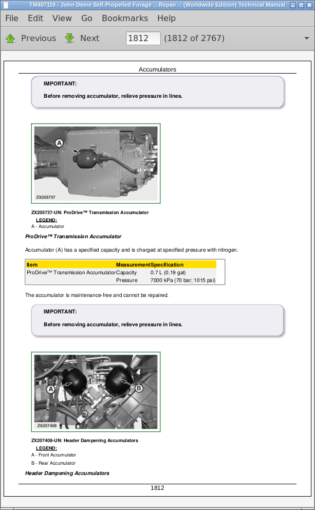
Accumulators
Check Accumulator
Recharge Accumulators
Lower Accumulator Pressure
Section 80: Machine Specific System
Group 05: Central Lubrication System
Summary of references, Central Lubrication System
Location of Distributors
Important Lubrication Instructions
Automatic Lubrication System
Quick Couplers
Group 10: Air Compressor System
Air Compressor System, Summary of References
Remove/Install Air Compressor System on 9 L Engine
Remove/Install Air Compressor System on 13.5 L Engine
Remove/Install Air Compressor System on QSK19 Engine (8700, 8800)
Group 15: Additive Dosing System
Additive Dosing System, Summary of References
Specifications
Change Additive Dosing System Nozzle
Additive Dosing System Cabinet
Check Filters
Remove/Install Tanks
Section 90: Operator’s Station
Group 05: Air Conditioner System (R-134a)
Air Conditioner System (R-134a), Summary of References
Specifications
Essential or Recommended Tools
Service Equipment and Tools
Other Material
Service Parts Kits
Hose and Tubing O-Ring Connection Torques
Air Conditioner - Important
Air Conditioner System - Safety at Work
Handling Refrigerant
Storage of Refrigerant Containers
R-134a Refrigerant
Service Work on Air Conditioner System
Test and Service Ports
Fill with Refrigerant Oil
Remove/Install Compressor
Charge Air Conditioner System
Group 10: Air Seat
Air Seat, Summary of References
Specifications
Essential or Recommended Tools
Remove/Install Operator Seat
Remove/Install Armrest Control Pivot
Remove/Install Operator Presence Switch
Remove/Install Seat Cushions
Remove/Install Lap Belt
Remove/Install Left-Hand Armrest
Operator Seat Exploded View
Remove/Install Operator Air Seat Suspension
Seat Suspension Component Overview
Remove/Install Seat Suspension Bellows
Remove/Install Vertical Shock Absorber Control Cable Handle
Remove/Install Vertical Shock Absorber Control Cable
Remove/Install Vertical Shock Absorber
Remove/Install Horizontal Shock Absorber
Remove/Install Fore/Aft Isolator Assembly
Remove/Install Fore/Aft Isolator Handle
Remove/Install Fore/Aft Isolator Locking Mechanism
Remove/Install Seat Suspension Compressor
Remove/Install Seat Level Indicator
Remove/Install Seat Suspension Air Spring
Remove/Install Seat Air Reservoir
Remove/Install Seat Height Control
Remove/Install Upper Seat Suspension Frame
Remove/Install Lower Seat Suspension Frame
Group 15: Cab
Cab, Summary of References
Specifications
Essential or Recommended Tools
Heating, Ventilating, and Air Conditioner System—HVAC (General Information)
Remove/Install Receiver/Dryer
Remove/Install Pressurizer Blower Motor
Remove/Install Recirculation Fan Motor
Remove/Install Recirculation Fan Motor Driver
Remove/Install Actuator Valves
Remove/Install Climate Control Unit
Remove/Install Evaporator
Remove/Install Heater Core
Replace Expansion Valve
Replace Air Conditioner High/Low-Pressure Switch
Remove Cab
Install Cab
Remove/Install Cab Windshield
Remove/Install Rear Window
Remove/Install Lower Cab Fascia
Remove/Install Front Portion of Cab Roof
Remove/Install Rear Portion of Cab Roof
Remove/Install Cab Inner Roof
Remove/Install Cab Headliner
Remove/Install Left-Hand Side Cab Door
Disassemble/Assemble Left-Hand Side Cab Door
Remove/Install Right-Hand Side Cab Door
Disassemble/Assemble Right-Hand Side Cab Door
Cab Door Latch Striker
Remove/Install Refrigerator
Remove/Install Refrigerator Doors
Remove/Install Refrigerator Control Unit
Remove/Install Refrigerator Thermostat
Section 99: Special Tools
Group 05: Special Tools (Available as Spare Parts)
Special Tools, Summary of References
Essential Tools for Engine
Essential Tools for Fuel, Air Intake, Cooling and Exhaust Systems
Essential Tools for Electrical System
Essential Tools for ProDrive™ Transmission
Essential Tools for Push Button Shift Transmission (PBST)
Essential Tools for Header Drive
Essential Tools for Right Feed Roll Drive
Essential Tools for Left Feed Roll Drive
Essential Tools for Power Distribution Gear
Essential Tools for Final Drives
Essential Tools for Brakes System
Essential Tools for Rear Axle
Essential Tools for Hydraulic System
Essential Tools for Operator’s Station
Essential Tools for Feeding System
Essential Tools for Cutterhead Assembly
Essential Tools for Discharge System
Section 110: Feeding System
Group 05: Feed Roll Housing
Feed Roll Housing, Summary of References
Specifications
Remove/Install Feed Roll Housing
Remove/Install Pivoting System
Remove/Install Feed Roll Housing Rollers
Group 10: Feed Roll Assembly
Feed Roll Assembly, Summary of References
Specifications
Essential or Recommended Tools
Other Material
Remove/Install Feed Roll Wear Plates
Remove/Install Scraper
Remove/Install Feed Roll
Repair Front Feed Rolls
Repair Rear Feed Rolls
Section 120: Cutterhead Assembly
Group 05: Cutterhead
Cutterhead, Summary of References
Specifications
Essential or Recommended Tools
Other Material
Open/Close Feed Roll Housing
Replace Cutterhead Knives
Remove/Install Cutterhead Assembly
Disassemble Cutterhead
Left-Hand Side Cutterhead Bearing—Repair
Right-Hand Side Cutterhead Bearing—Repair
Group 10: Knife Sharpening Device
Knife Sharpening Device, Summary of References
Specifications
Essential or Recommended Tools
Other Material
Knife Sharpening Sensor Repair
Knife Sharpening Door Repair
Knife Sharpening Device Repair
Adjust Knife Sharpening Device Position
Grinding Tool Exploded View
Grinding Tool Repair
Replace Sharpening Stone
Sharpening Stone Control
Group 15: Bottom and Transition Chutes
Bottom and Transition Chutes, Summary of References
Specifications
Essential or Recommended Tools
Remove/Install Spiral Floor
Remove/Install Recutter Floor
Remove/Install Deflectors
Remove/Install Discharge Chute Panels
Remove/Install Grass Chute Cover
Install Discharge Chute
Group 20: Stationary Knife
Stationary Knife, Summary of References
Specifications
Other Material
Remove/Install Stationary Knife
Remove/Install Stationary Knife Support Diffuser
Remove/Install Stationary Knife Arms
Group 25: Kernel Processor
Summary of references, Kernel Processor
Specifications
Essential or Recommended Tools
Other Material
Operate the Kernel Processor—Type A
Operate the Kernel Processor—Type B
Remove/Install Pulleys
Remove/Install Gap Control Structure
Repair Kernel Processor
Group 30: KernelStar™ Processor
Summary of references, KernelStar™ Processor
Specifications
Essential or Recommended Tools
Other Material
Operate the Kernel Processor—Type A
Operate the Kernel Processor—Type B
Remove/Install Pulleys
Remove/Install Gap Control Structure
Repair KernelStar™
Assemble Bevel Disk Rolls
Section 130: Discharge System
Group 05: Discharge fan
Discharge fan, Summary of references
Specifications
Essential or Recommended Tools
Remove/Install Blower Wear Plates
Remove/Install Discharge Tower Wear Plates
Remove/Install Blower Side Wear Plates
Remove/Install Blower Scrapers
Replace and Adjust Blower Paddles
Group 10: Blower Rotor
Blower Rotor, Summary of References
Specifications
Essential or Recommended Tools
Other Material
Remove/Install Blower Rotor Drive Pulley
Remove/Install Kernel Processor Drive Pulley
Remove/Install Blower Rotor Self-Aligning Bearing on Right-Hand Side
Remove/Install Blower Rotor Self-Aligning Bearing on Left-Hand Side
Remove/Install Blower Rotor
Group 15: Discharge Spout
Discharge Spout, Summary of References
Specifications
Other Material
Remove/Install Discharge Spout Motor Gear
Adjust Discharge Spout Motor Gear
Remove/Install Discharge Spout
Remove/Install Discharge Spout Turning Device
Remove/Install HarvestLab™ Sensor Version 1.4 (Option)
Remove/Install HarvestLab™ 3000 Sensor (Option)
Discharge Spout Service Opening and Wear Plates
John Deere Self-Propelled Forage Harvesters Models 8100, 8200, 8300, 8400, 8500, 8600, 8700, 8800 (Worldwide Edition) Service Repair Technical Manual (TM407119)
![]()