
John Deere Hay and Forage Mower Conditioners Models 830, 835 All Inclusive Service Technical Manual (TM301319)

Complete Diagnosis and Repair manual with Electrical Wiring Diagrams for John Deere 830, 835 Forage Mower-Conditioner (European Edition), with all the shop information to maintain, diagnose, repair, and rebuild like professional mechanics.
John Deere Hay and Forage Mower Conditioners Models 830 and 835 workshop Diagnostic and Repair manual includes:
* Numbered table of contents easy to use so that you can find the information you need fast.
* Detailed sub-steps expand on repair procedure information
* Numbered instructions guide you through every repair procedure step by step.
* Troubleshooting and electrical service procedures are combined with detailed wiring diagrams for ease of use.
* Notes, cautions and warnings throughout each chapter pinpoint critical information.
* Bold figure number help you quickly match illustrations with instructions.
* Detailed illustrations, drawings and photos guide you through every procedure.
* Enlarged inset helps you identify and examine parts in detail.
John Deere Hay and Forage Mower Conditioners Models 830, 835 All Inclusive Technical Manual (Diagnosis Operation Test Repair Service).PDF
John Deere Hay and Forage Mower Conditioners Models 830, 835 All Inclusive Technical Manual (Diagnosis Operation Test Repair Service).epub
tm301328 - Faucheuses- conditionneuses 830 et 835 - (Édition européenne) Manuel Technique.epub
tm301328 - Faucheuses- conditionneuses 830 et 835 - (Édition européenne) Manuel Technique.pdf
tm301367 - 830 och 835 Rotorslåtterkrossar - (Europeisk utgåva) Teknisk manual.pdf
tm301367 - 830 och 835 Rotorslåtterkrossar - (Europeisk utgåva) Teknisk manual.epub
Total Pages: 701 pages
File Format: PDF/EPUB/MOBI/AZW (PC/Mac/Android/Kindle/iPhone/iPad; bookmarked, ToC, Searchable, Printable)
Language: English / French / Swedish
MAIN SECTIONS
Foreword
General
Safety
General Information
Lubricants
Torques for Hardware
Electrical System: Repair
Electrical Repair: Connectors
Electrical Repair: Actuators
Power Train
Power Train: General Information
Driveline Repair
Tongue Drive Shaft
Drive Belts
Hitch and Tongue Gear Cases
Platform Gear Case
Roll Drive Gear Case (Roll Conditioner)
Hydraulics
Hydraulics: General Information
Lift Cylinders
Swing Cylinder
Windrow Forming Shield Cylinder
Cutting Height Adjustment Cylinder
Windrow Forming Shield Relief Valve
Windrow Forming Shield Diverter Valve
Miscellaneous
Wheels and Wheel Support Assembly
Carrier Frame and Tongue
Carrier Frame
Lift Arm
Limiting Chain
Tongue
Cutting Components
Cutting Components: General Information
Cutterbar Repair
Disks and Knives
Cutterbar Assembly
Conditioner
Conditioner: General Information
Roll Arms and Bearings
Rolls
Impeller
Platform
Platform: General Information
Platform Repair
Observable Symptom
Troubleshooting
Electrical System
Electrical System: General Information
Electric System: Road Light
Electrical System: Windrow Forming Shield Diverter Valve
Hydraulic Systems
Hydraulic Systems: Safety and General Information
Hydraulic Systems - Theory of Operation
Hydraulic System Component Information
Hydraulic Connections: Windrow Forming Shield
Hydraulic Component Information
Special Tools
Special Tools (Dealer-Fabricated)
Special Tools (Available as Spare Parts)
TABLE OF CONTENTS................1
Section 10: General................14
Group 05: Safety................14
Recognize Safety Information................17
Understand Signal Words................18
Follow Safety Instructions................19
Operate Mower-Conditioner Safely................20
Keep Riders Off Machine................21
Handle Fluids Safely—Avoid Fires................22
Prepare for Emergencies................23
Stay Clear of Rotating Drivelines................24
Avoid Injury From Thrown Objects................26
Use Safety Lights and Devices................27
Use a Safety Chain................28
Tow Loads Safely................29
Support Machine Properly................30
Wear Protective Clothing................31
Work in Clean Area................32
Service Machines Safely................33
Illuminate Work Area Safely................34
Replace Safety Signs................35
Use Proper Lifting Equipment................36
Remove Paint Before Welding or Heating................37
Avoid Heating Near Pressurized Fluid Lines................38
Service Tires Safely................39
Practice Safe Maintenance................40
Use Proper Tools................41
Construct Dealer-Made Tools Safely................42
Dispose of Waste Properly................43
Live With Safety................44
Group 10: General Information................14
General Information - Summary of References................46
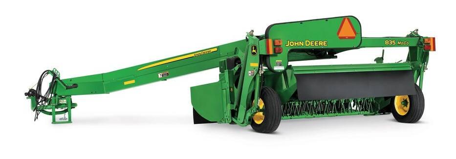
830 and 835 Machine Description................47
Group 15: Lubricants................15
Lubricants - Summary of References................49
Grease................50
Cutterbar and Roll Drive Gear Case Oil................51
Swivel Gear Case Oil................52
Platform Gear Case Oil................53
Alternative and Synthetic Lubricants................54
Mixing of Lubricants................55
Lubricant Storage................56
Perform Lubrication and Maintenance................57
Group 20: Torques for Hardware................15
Metric Bolt and Screw Torque Values................60
Unified Inch Bolt and Screw Torque Values................62
Section 40: Electrical System: Repair................64
Group 10: Electrical Repair: Connectors................64
Electrical Repair: Connectors - Summary of References................66
Electrical Repair: Connectors - Special Tools................67
Electrical Connector Handling................68
Disconnect the Electrical Circuit................69
WEATHER PACK Connectors................70
Insulated and Non-Insulated Terminals................73
Individual Terminals................74
Harness Repair (Splice Broken or Cut Wire)................76
Harness Repair - Splice Connector................78
Group 15: Electrical Repair: Actuators................64
Electrical Repair: Actuators - Summary of References................80
Remove and Install Windrow Forming Shield Diverter Solenoid Y6................81
Section 50: Power Train................82
Group 05: Power Train: General Information................82
Power Train: General Information - Summary of References................86
Power Train Operation: Impeller Conditioner................87
Power Train Operation: Roll Conditioner................89
Group 15: Driveline Repair................82
Driveline Repair - Summary of References................92
Driveline Repair - Other Material................93
Driveline Repair - Specifications................94
Driveline Repair - Special Tools................95
Remove PTO Hookup Driveline................96
Disassemble and Assemble PTO Hookup Lock-Back Collar................98
Exploded View of PTO Hookup Driveline................100
Install PTO Hookup Driveline................101
Remove and Install Tongue Pivot Driveline................103
Remove and Install Platform Driveline................105
Exploded View of Tongue Pivot and Platform Driveline................107
Disassemble and Assemble PTO Hookup, Tongue Pivot and Platform Driveline................108
Disassemble and Assemble Overrunning Coupler................113
Disassemble and Assemble Platform Driveline Slip Clutch (540 rpm only)................115
Disassemble and Assemble Cutterbar Driveline................121
Remove Roll Driveline (Roll Conditioner)................124
Disassemble and Assemble Upper Roll Driveline (Roll Conditioner)................126
Disassemble and Assemble Lower Roll Driveline (Roll Conditioner)................128
Install Roll Driveline (Roll Conditioner)................130
Group 25: Tongue Drive Shaft................82
Tongue Drive Shaft - Summary of References................133
Tongue Drive Shaft - Other Material................134
Tongue Drive Shaft - Specifications................135
Remove Long Tongue Drive Shaft................136
Install Long Tongue Drive Shaft................138
Remove Short Tongue Drive Shaft................140
Install Short Tongue Drive Shaft................142
Group 30: Drive Belts................83
Drive Belts - Summary of References................144
Drive Belts - Other Material................145
Drive Belts - Specifications................146
Remove Main Drive Belt................147
Install Main Drive Belt................149
Adjust Main Drive Belt Tension................151
Remove and Install Fixed Idler................152
Disassemble and Assemble Adjustable Idler Assembly................156
Remove and Install Drive and Driven Sheave Bearing................159
Remove and Install Return Sheave Bearing................162
Remove and Install Conditioner Drive Belt (Impeller Conditioner)................164
Adjust Conditioner Drive Belt Tension (Impeller Conditioner)................168
Disassemble and Assemble Conditioner Adjustable Idler Assembly (Impeller Conditioner)................169
Remove and Install Conditioner Drive Belt (Roll Conditioner)................171
Adjust Conditioner Drive Belt Tension (Roll Conditioner)................174
Disassemble and Assemble Conditioner Adjustable Idler Assembly (Roll Conditioner)................175
Group 40: Hitch and Tongue Gear Cases................83
Hitch and Tongue Gear Cases - Summary of References................179
Hitch and Tongue Gear Cases - Other Material................180
Hitch and Tongue Gear Cases - Specifications................181
Hitch and Tongue Gear Cases - Special Tools................182
Remove and Install Hitch and Tongue Gear Case Assembly................183
Disassemble Hitch and Tongue Drive Gear Cases................187
Inspect Hitch and Tongue Drive Gear Cases................195
Assemble Hitch and Tongue Drive Gear Cases................197
Group 47: Platform Gear Case................83
Platform Gear Case - Summary of References................214
Platform Gear Case - Other Material................215
Platform Gear Case - Specifications................216
Platform Gear Case - Special Tools................217
Remove and Install Platform Gear Case................218
Exploded View Of Platform Gear Case................221
Disassemble and Assemble Platform Gear Case................223
Group 49: Roll Drive Gear Case (Roll Conditioner)................84
Roll Drive Gear Case (Roll Conditioner) - Summary of References................251
Roll Drive Gear Case (Roll Conditioner) - Other Material................252
Roll Drive Gear Case (Roll Conditioner) - Specifications................253
Roll Drive Gear Case (Roll Conditioner) - Special Tools................254
Remove Roll Drive Gear Case (Roll Conditioner)................255
Disassemble and Assemble Roll Drive Gear Case (Roll Conditioner)................257
Install Roll Drive Gear Case (Roll Conditioner)................263
Section 70: Hydraulics................265
Group 05: Hydraulics: General Information................265
Hydraulics: General Information - Summary of References................268
Lift Cylinders Operation................269
Swing Cylinder Operation................270
Windrow Forming Shield Cylinder Operation................271
Cutting Height Adjustment Cylinder Operation................273
Group 15: Lift Cylinders................265
Lift Cylinders - Summary of References................275
Lift Cylinders - Other Material................276
Lift Cylinders - Specifications................277
Remove and Install Lift Cylinder................278
Disassemble and Assemble Right Lift Cylinder................281
Disassemble and Assemble Left Lift Cylinder................287
Phase Lift Cylinders................294
Group 20: Swing Cylinder................265
Swing Cylinder - Summary of References................296
Swing Cylinder - Other Material................297
Swing Cylinder - Specifications................298
Remove and Install Swing Cylinder................299
Disassemble and Assemble Swing Cylinder................302
Group 25: Windrow Forming Shield Cylinder................265
Windrow Forming Shield Cylinder - Summary of References................306
Windrow Forming Shield Cylinder - Other Material................307
Windrow Forming Shield Cylinder - Specifications................308
Remove Windrow Forming Shield Cylinder................309
Disassemble Windrow Forming Shield Cylinder................312
Assemble Windrow Forming Shield Cylinder................314
Install Windrow Forming Shield Cylinder................316
Group 30: Cutting Height Adjustment Cylinder................265
Cutting Height Adjustment Cylinder - Summary of References................319
Cutting Height Adjustment Cylinder - Specifications................320
Remove Cutting Height Adjustment Cylinder................321
Disassemble Cutting Height Adjustment Cylinder................326
Assemble Cutting Height Adjustment Cylinder................327
Install Cutting Height Adjustment Cylinder................328
Group 50: Windrow Forming Shield Relief Valve................672
Windrow Forming Shield Relief Valve - Summary of References................333
Windrow Forming Shield Relief Valve - Specifications................334
Remove Control Windrow Forming Shield Relief Valve................672
Disassemble Windrow Forming Shield Relief Valve................672
Assemble Windrow Forming Shield Relief Valve................672
Install Control Windrow Forming Shield Relief Valve................672
Group 55: Windrow Forming Shield Diverter Valve................668
Windrow Forming Shield Diverter Valve - Summary of References................343
Windrow Forming Shield Diverter Valve - Specifications................344
Disassemble Windrow Forming Shield Diverter Valve................668
Assemble Windrow Forming Shield Diverter Valve................668
Section 80: Miscellaneous................348
Group 05: Wheels and Wheel Support Assembly................348
Wheels and Wheel Support Assembly - Summary of References................350
Wheels and Wheel Support Assembly - Specifications................351
Remove and Install Wheel................352
Disassemble and Assemble Wheel Bearings................355
Disassemble and Assemble Wheel Support................357
Section 81: Carrier Frame and Tongue................360
Group 15: Carrier Frame................360
Carrier Frame - Summary of References................362
Adjust Carrier Frame Height................363
Group 20: Lift Arm................360
Lift Arm - Summary of References................367
Lift Arm - Specifications................368
Remove Left Lift Arm................369
Inspect Left Lift Arm................372
Install Left Lift Arm................373
Remove Right Lift Arm................375
Install Right Lift Arm................377
Group 25: Limiting Chain................360
Limiting Chain - Summary of References................379
Position Limiting Chain................380
Group 30: Tongue................360
Tongue - Summary of References................383
Tongue - Specifications................384
Tongue - Special Tools................385
Remove Tongue................386
Install Tongue................389
Section 100: Cutting Components................392
Group 05: Cutting Components: General Information................392
Cutting Components: General Information - Summary of References................395
Cutterbar Description................396
Group 10: Cutterbar Repair................392
Cutterbar Repair - Summary of References................398
Cutterbar Repair - Other Material................399
Cutterbar Repair - Specifications................400
Cutterbar Repair - Special Tools................401
Drain Oil From Cutterbar................402
Remove and Install Cutterbar................404
Remove and Install Single Intermediate Module from Cutterbar................410
Remove and Install Converging Drums and Shields................419
Check Dented Module................430
Repair Dented Module................431
Disassemble and Assemble Cutterbar................433
Remove and Install Idler Gear Bearing From Idler Gear................440
Remove and Install Left End Quill Assembly................447
Remove and Install Right End or Intermediate Quill Assemblies................451
Cutterbar Quill and Pinion Gear Timing Detail (Disks Rotate Towards Cutterbar Center of Cutterbar)................456
Check Quill Bearing End Play................458
Inspect Idler Gear Bearing................460
Disassemble and Assemble Quill Assembly................462
Replace Left End Disk Driver................468
Replace Intermediate Disk Drivers................473
Replace Right End Disk Driver................478
Group 15: Disks and Knives................392
Disks and Knives - Summary of References................484
Disks and Knives - Specifications................485
Remove Disks................486
Install and Synchronize Disks................488
Check Knife Wear................490
Check Disk Wear................495
Remove and Install Knives................497
Replace Wear Cap On Knife Bolt................501
Replace Crop Accelerators (If Equipped)................503
Group 25: Cutterbar Assembly................393
Cutterbar Assembly - Summary of References................506
Cutterbar Assembly - Specifications................507
Remove and Install Cross Tube................508
Section 110: Conditioner................510
Group 05: Conditioner: General Information................510
Conditioner: General Information - Summary of References................513
Conditioner Description................514
Group 15: Roll Arms and Bearings................510
Roll Arms and Bearings - Summary of References................517
Roll Arms and Bearings - Other Material................518
Roll Arms and Bearings - Specifications................519
Remove Upper Roll Arm and Bearing (Left Side)................520
Install Upper Roll Arm and Bearing (Left Side)................524
Remove Upper Roll Arm and Bearing (Right Side)................528
Install Upper Roll Arm and Bearing (Right Side)................532
Replace Lower Roll Bearing (Left Side)................536
Replace Lower Roll Bearing (Right Side)................538
Group 20: Rolls................510
Rolls - Summary of References................541
Rolls - Other Material................542
Rolls - Specifications................543
Rolls - Special Tools................544
Remove and Install Lower Roll................545
Remove and Install Upper Roll................548
Adjust Roll Alignment................552
Adjust Roll Timing................555
Adjust Roll Pressure................559
Adjust Roll Spacing................561
Group 25: Impeller................510
Impeller - Summary of References................563
Impeller - Other Material................564
Impeller - Specifications................565
Remove Impeller................566
Install Impeller................568
Remove Impeller Bearing (Left Side)................569
Install Impeller Bearing (Left Side)................571
Remove Impeller Bearing (Right Side)................574
Install Impeller Bearing (Right Side)................577
Change Impeller Speed................580
Replace Rotor Tines................583
Section 120: Platform................585
Group 05: Platform: General Information................585
Platform: General Information - Summary of References................587
Platform Description................588
Group 10: Platform Repair................585
Platform Repair - Summary of References................590
Platform Repair - Other Material................591
Platform Repair - Specifications................592
Remove and Install Platform................593
Adjust Platform Float................597
Adjust Cutting Height - Manual Control................599
Adjust Cutting Height - Hydraulic Control................601
Remove and Install Gauge Shoes................603
Section 212: Observable Symptom................606
Group 10: Troubleshooting................606
Troubleshooting - Summary of References................608
Driveline Malfunctions................609
Telescoping Hook-Up Locking System................611
End Yokes................612
Inboard Yokes................613
Profile Tubes................614
Telescoping Hook-Up Guards................615
Diagnose Lift Circuit Malfunctions................616
Diagnose Swing Circuit Malfunctions................618
Diagnose Carrier Frame and Tongue Malfunctions................619
Diagnose Roll Conditioner Malfunctions................620
Diagnose Impeller Conditioner Malfunctions................622
Section 240: Electrical System................623
Group 05: Electrical System: General Information................623
Electrical System: General Information - Summary of References................625
Open Circuit................626
Grounded Circuit................627
Shorted Circuit................628
Symbols in System Diagrams................630
Component Identification Table................634
Electrical Circuit Malfunctions................636
Group 15: Electric System: Road Light................623
Electrical System: Road Light - Summary of References................638
Electrical System: Road Light - Wiring Harness List................639
Electrical System: Road Light - Component Identification................640
Electrical System: Road Light - Component Location................641
Electrical System: Road Light - Wiring Diagram................642
Group 20: Electrical System: Windrow Forming Shield Diverter Valve................668
Electrical System: Windrow Forming Shield Diverter Valve - Summary of References................644
Electrical System: Windrow Forming Shield Diverter Valve - Wiring Harness List................645
Electrical System: Windrow Forming Shield Diverter Valve - Component Identification................646
Electrical System: Windrow Forming Shield Diverter Valve - Component Location................647
Electrical System: Windrow Forming Shield Diverter Valve - Wiring Diagram................648
Section 270: Hydraulic Systems................649
Group 05: Hydraulic Systems: Safety and General Information................649
Hydraulic Systems: Safety and General Information - Summary of References................651
Avoid High-Pressure Fluids................652
Cleanliness................653
Testing Precautions................654
Hydraulic Symbols (As Defined by ISO 1219)................655
Group 20: Hydraulic Systems - Theory of Operation................649
Hydraulic Systems - Theory of Operation - Summary of References................658
Hydraulic Systems - Theory of Operation: Windrow Forming Shield Diverter Valve................668
Hydraulic Systems - Theory of Operation: Windrow Forming Shield Relief Valve................672
Section 279: Hydraulic System Component Information................661
Group 35: Hydraulic Connections: Windrow Forming Shield................664
Hydraulic Connections: Windrow Forming Shield - Summary of References................663
Hydraulic Connections: Windrow Forming Shield................664
Group 40: Hydraulic Component Information................661
Hydraulic Component Information - Summary of References................666
Hydraulic Component Information - Specifications................667
Windrow Forming Shield Diverter Valve................668
Check for Leaks at Windrow Forming Shield Diverter Valve................669
Windrow Forming Shield Relief Valve................672
Check Windrow Forming Shield Relief Valve Pressure................673
Section 399: Special Tools................675
Group 05: Special Tools (Dealer-Fabricated)................675
Special Tools (Dealer-Fabricated) - Summary of References................677
Gear Case Lifting Eye................678
Tongue Lifting Bracket................679
DFEX1823A Backlash Measuring Strap................681
Group 10: Special Tools (Available as Spare Parts)................675
Special Tools (Available as Spare Parts) - Summary of References................683
D01044AA - Bushing, Bearing and Seal Driver Kit................684
D01218AA - Knife-Edge Puller................685
D01243AA - Knife-Edge Puller................686
D05304ST - Dial Indicator................687
D17507CI - Inside Micrometer................688
E83373 - Wrench................689
FKM10461 - Wiring Harness Repair Kit................690
FKM10467 - Crimping Pliers................691
FKM10468 - Crimping Pliers................692
JDG364 - Extraction Tool................693
JDG707 - Crimping Pliers................694
JDG783 - Crimping Pliers................695
JDT31 - Ball Loading Sleeve................696
KLM10019-1 - Crimping Pliers................697
John Deere Hay and Forage Mower Conditioners Models 830, 835 All Inclusive Service Technical Manual (TM301319)
![]()