
John Deere Hay and Forage Round Balers Models 842, 852, 854, 862, 864 All Inclusive Service Technical Manual (TM300119)
Complete Diagnosis Repair manual with Electrical Wiring Diagrams for John Deere Hay and Forage Round Balers Models 842, 852, 854, 862 and 864 (Worldwide Edition), with all the shop information to maintain, diagnose, and service like professional mechanics.
John Deere 842, 852, 854, 862, 864 Hay & Forage Round Balers workshop Diagnostics Repair Technical Service Manual includes:
* Numbered table of contents easy to use so that you can find the information you need fast.
* Detailed sub-steps expand on repair procedure information
* Numbered instructions guide you through every repair procedure step by step.
* Troubleshooting and electrical service procedures are combined with detailed wiring diagrams for ease of use.
* Notes, cautions and warnings throughout each chapter pinpoint critical information.
* Bold figure number help you quickly match illustrations with instructions.
* Detailed illustrations, drawings and photos guide you through every procedure.
* Enlarged inset helps you identify and examine parts in detail.
TM300119 - John Deere Hay and Forage Round Balers Models 842, 852, 854, 862, 864 All Inclusive Technical Manual (Diagnosis Operation Test Repair Service).PDF
Total Pages: 2,002 pages
File Format: PDF (bookmarked, ToC, Searchable, Printable, high quality)
Language: English
MAIN SECTIONS
Electrical System - Repair
Connectors
Sensors and Switches
Actuators
BaleTrak and BaleTrak Plus Monitor
Power Train
Walterscheid Powerline
Baler Main Drive Shaft
Shear Bolt Clutch
Walterscheid Slip Clutch
Cam-Type Cut Out Clutch
Gear Case
Chains
Sprocket Alignment
Braking System - Repair
Air Brakes
Hydraulic Brakes
Brake Shoe and Drum
Hydraulic System
Bale Density Control Valve
Hydraulic Cylinders
Hydraulic Hoses
Gate Lock Valve
Rotary Feeder Hydraulic Components
Miscellaneous
Axle
Gate Latch
Lubrication System - Repair
Drive Chain Lubrication
Pickup Repair
Rotary Feeding Device
Bale Chamber
Net Tying System
Twine Tying System
Diagnostic Trouble Codes
Diagnostic Trouble Codes for ISOBUS Baler
Diagnostic Trouble Codes for BaleTrak Control
Description
Battery Voltage
Bale Size Potentiometer R2 or RB311
Right Bale Shape Potentiometer R4 or RB322
Left Bale Shape Potentiometer R3 or RB321
Twine Actuator M1
Net Actuator M2
Soft Core Valves Y1, Y5 and Y6
Pickup Solenoid Valve Y4
Knife Solenoid Valve Y3
Drop Floor Solenoid Valve Y2
Cleaning Auger S12
Lower Drive Roll RPM Sensor S6
Twine Pulley Sensors S7/S8
Net Cut Switch S4 or Sensor SB414
Right Gate Switch S1 or Sensor SB337
Left Gate Switch S2 or Sensor SB336
Oversize Bale Switch S3 or sensor SB317
Positive Analog Reference
EPROM
Observable Symptoms
Electrical System
General Information
Test Equipment
Electrical Diagram/Battery Wiring Harness
Electrical System/ELC Plus Monitor (Electronic Tying Control)
Electrical Diagram/ELC Plus Monitor (Electronic Tying Control)
Electrical System/BaleTrak Control
Electrical Diagram/BaleTrak Monitor
Diagnostic Modes/BaleTrak Monitor
Electrical Diagram/ISOBUS Baler
Diagnostic Tests - ISOBUS Baler
Diagnostic Modes/ISOBUS Baler
Advanced Machine Settings Mode/ISOBUS Baler
Connector and Component Information
Lubrication System - Operation and Tests
Air Brake System - Operation and Tests
Hydraulic Brake System - Operation and Tests
Hydraulic System - Operation and Tests
Safety
General Information
Bale Density/Gate Control - Description
Bale Density/Gate Control - Tests
Pickup Lift System (Baler without Precutter Device)
Rotary Feeder Hydraulic System without Precutter Device - Description
Rotary Feeder Hydraulic System without Precutter Device - Tests
Rotary Feeder Hydraulic System with Precutter Device - Description
Rotary Feeder Hydraulic System with Precutter Device - Tests
Net Tying - Operation and Tests
Special Tools
tm300119 - 842, 852, 854, 862, and 864 Round Balers -: (Worldwide Edition)
Table of Contents
Foreword
Section 05: Safety
Group 05: Safety Information
Prevent Battery Explosions
Prepare for Emergencies
Prevent Acid Burns
Avoid High-Pressure Fluids
Support Machine Properly
Wear Protective Clothing
Service Machines Safely
Work in Clean Area
Remove Paint Before Welding or Heating
Avoid Heating Near Pressurized Fluid Lines
Illuminate Work Area Safely
Replace Safety Signs
Use Proper Lifting Equipment
Service Tires Safely
Practice Safe Maintenance
Use Proper Tools
Decommissioning — Proper Recycling and Disposal of Fluids and Components
Live With Safety
Relieve Hydraulic Pressure Safely
Safety Information - Air Brake System
Section 10: General
Group 10: Serial Numbers
Baler Serial Number Record
Serial Number Plate Description
Group 15: Torques for Hardware
Unified Inch Bolt and Screw Torque Values
Metric Bolt and Screw Torque Values
Group 20: Lubrication
High Viscosity Gear Case Oil
Grease
Multiluber Chain Oil
Group 25: General Information
Locking Collars for Shaft Bearings
Section 40: Electrical System — Repair
Group 05: Connectors
Special or Essential Tools
Electrical Connector Handling
Disconnecting Electrical Circuit
Insulated and Non-Insulated Connectors
Replacing Small MATE-N-LOK MATE-N-LOK is a trademark of AMP, Inc. Contacts in Connector Housings
Replacing SURE-SEAL SURE-SEAL is a trademark of ITT Cannon Electric. Connector Bodies
Replace CPC, Large MATE-N-LOK and METRIMATE CPC, MATE-N-LOK, and METRIMATE are trademarks of AMP Inc. Pin Type Connectors
DEUTSCH Connectors
WEATHER PACK Connectors
METRI PACK Connectors For Metri Pack connectors, 150 series
Replacing SCHLEMMER SCHLEMMER is a trademark of Josef Schlemmer GmbH. Connectors
CINCH Connectors
Harness Repair (Splice Broken or Cut Wire)
Harness Repair—Splice Connector
Group 10: Sensors and Switches
Specifications
Replace Sensors SB337, SB336, SB317 and SB414
Gate Latch Switch S1 (842, 852, 854)(S.N. —134999)
Gate Latch Sensor SB337 (842, 852, 854 with BaleTrak Monitor)(S.N. 135000—)
Gate Latch Switches S1, S2 (862 with ELC Monitor and 862, 864 with BaleTrak Monitor) or SB333, SB334 (ISOBUS Baler)(S.N. —134999)
Gate Latch Sensors SB336, SB337 (862, 864 with BaleTrak Monitor or ISOBUS)(S.N. 135000—)
Oversize Bale Switch S3 (Baler with ELC or BaleTrak Monitor) or SB312 (ISOBUS Baler)(S.N. —134999)
Oversize Bale Sensor SB317 (842 with BaleTrak Monitor)(S.N. 135000—)
Oversize Bale Sensor SB317 (852, 854 with BaleTrak Monitor)(S.N. 135000—)
Oversize Bale Sensor SB317 (862, 864 with BaleTrak Monitor or ISOBUS)(S.N. 135000—)
Net Cut Switch S4 (Baler with ELC or BaleTrak Monitor) or SB412 (ISOBUS Baler)(S.N. —134999)
Net Cut Sensor SB414 (Baler with BaleTrak Monitor or ISOBUS)(S.N. 135000—)
Bale Size Switch S5 (Baler with ELC Plus Monitor)
Soft Core Switch S6 (Baler with ELC Plus Monitor)
Baler Rotation Speed Sensor S6 (Baler with BaleTrak Monitor) or SB362 (ISOBUS Baler)
Twine Pulley Sensors S7, S8 (Baler with BaleTrak Monitor)
Precutter Knife Sensor S10 (Baler with BaleTrak Monitor) or SB553 (ISOBUS Baler)
Cleaning Auger Sensor S12 (Baler with BaleTrak Monitor) or SB363 (ISOBUS Baler)
Drop Floor Sensor S13 (854 and 864) or SB532 (ISOBUS Baler)
Bale Size Potentiometer R2 (Baler with BaleTrak Monitor)
Bale Size Potentiometer RB311 (ISOBUS Baler)
Bale Shape Potentiometers R3, R4 or RB321, RB322 (Baler with BaleTrak Monitor)
Bale Shape Potentiometers RB321, RB322 (ISOBUS Baler)
Gate Position Potentiometer RB331 (ISOBUS Baler)
Bale Discharging Ramp Sensor SB341 (ISOBUS Baler)
B-Wrap Sensor SB416
Group 15: Actuators
Other Material
Specifications
Removing and Installing Twine Tying Actuator M1
Remove Net Tying Actuator M2
Install Net Tying Actuator M2
Disassembling/Assembling Twine Tying Actuator M1 and Net Tying Actuator M2
Group 50: BaleTrak and BaleTrak Plus Monitor
Specifications
Replace BaleTrak EPROM
Disassembling BaleTrak Monitor
Assembling BaleTrak Monitor
Reprogramming BaleTrak Software
Section 50: Power Train
Group 10: Walterscheid Powerline
Special or Essential Tools
Bearing Extractor
Remove Powerline With Shear Bolt
Remove Powerline With Slip Clutch
Remove Powerline with Cam-Type Cut Out Clutch
Installing Powerline with Cam-Type Cut Out Clutch
Remove Powerline Joint Shield
Install Powerline Joint Shield
Disassemble CV Joint
Assemble CV Joint
Removing Half Guard
Installing Half Guard
Disassemble Hook-Up
Assemble Hook-Up
Disassembling Coupler
Assembling Coupler
Exploded View of Powerline for Baler with 540 rpm Gear Case (Clutch DC212746)
Exploded View of Powerline for Baler with 1000 rpm Gear Case (Clutch DC212747)
Exploded View of Powerline (Clutch DC44090 and DC44092)
Group 20: Baler Main Drive Shaft (Baler without Rotary Feeder Device)
Other Material
Specifications
Drive Shaft (Baler without Rotary Feeder Device)
Remove Drive Shaft (Baler without Rotary Feeder Device)
Install Drive Shaft (Baler without Rotary Feeder Device)
Group 25: Baler Main Drive Shaft (Baler With Rotary Feeder Device)
Other Material
Specifications
Drive Shaft (Baler with Rotary Feeder Device)
Remove Drive Shaft (Baler with Rotary Feeder Device)
Install Drive Shaft (Baler with Rotary Feeder Device)
Group 30: Shear Bolt Clutch
Specifications
Disassembling Shear Bolt Clutch
Assembling Shear Bolt Clutch
Group 35: Walterscheid Slip Clutch
Specifications
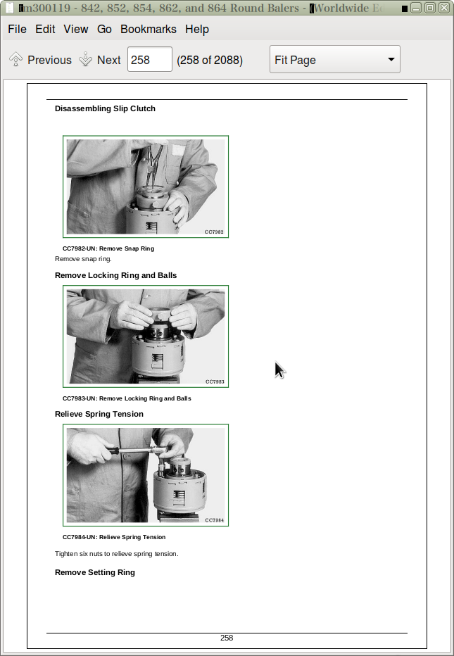
Disassembling Slip Clutch
Exploded View of Walterscheid Slip Clutch
Assembling Slip Clutch
Install Setting Ring
Group 40: Cam-Type Cut Out Clutch
Other Material
Specifications
Disassemble Cam-Type Cut Out Clutch
Adjust Cam-Type Cut Out Clutch
Exploded View of Cam-Type Cut Out Clutch
Assemble Cam-Type Cut Out Clutch
Group 50: Gear Case (Baler without Rotary Feeder Device)
Recommended Tools
Service Equipment and Tools
Other Material
Specifications
Remove Gear Case (Baler without Rotary Feeder Device)
Disassemble Gear Case (Baler without Rotary Feeder Device)
Exploded View of Gear Case (Baler without Rotary Feeder Device)
Inspect Gear Case
Assemble Gear Case (Baler without Rotary Feeder Device)
Install Gear Case (Baler without Rotary Feeder Device)
Group 55: Gear Case (Baler with Rotary Feeder Device)
Recommended Tools
Service Equipment and Tools
Other Material
Specifications
Remove Gear Case (Baler with Rotary Feeder Device)
Disassemble Gear Case (Baler with Rotary Feeder Device)
Exploded View of Gear Case (Baler with Rotary Feeder Device)
Inspect Gear Case
Assemble Gear Case (Baler with Rotary Feeder Device)
Install Gear Case (Baler with Rotary Feeder Device)
Group 60: Chain
Check the Chain Wearing
Adjusting 1.81 m (5 ft 11 in.) Pickup Drive Chains
Adjusting 2.00 m (6 ft 7 in.) HiFlow Pickup Drive Chains
Adjusting 2.20 m (7 ft 3 in.) HiFlow Pickup Drive Chains
Adjust Pickup Drive Chains (Baler with Rotary Feeder Pickup)
Adjust Bottom Roll Drive Chain (Baler with Rotary Feeder Pickup)
Adjust Main Drive Chain
Adjust Upper Drive Roll Chain (842 Only)
Adjust Upper Drive Roll Chain (Except 842)
Adjust Rotary Feeder Drive Chain
Adjust Top Idler Roll Drive Chain
Group 70: Sprocket Alignment
Specifications
Check and Adjust Upper Drive Sprocket Alignment
Check and Adjust Double Drive Sprocket Alignment for 1.81 m (5 ft 11 in.) Pickup (Baler without Rotary Feeder Device)
Check and Adjust Crankshaft Sprocket Alignment for 2.20 m (7 ft 3 in.) Pickup (Baler without Rotary Feeder Device)
Check and Adjust Feeding Device Chains Sprocket Alignment (Baler with Rotary Feeder Device)
Section 60: Braking System — Repair
Group 05: Air Brakes
Specifications
Preliminary Check
General Information
Drain Air Brake Reservoir
Clean Air Filters
Install Plug-in Connections
Remove Reservoir
Install Reservoir
Remove Relay Emergency Valve
Install Relay Emergency Valve
Remove Brake Cylinder
Adjust Brake Cylinder Clevis
Install Brake Cylinder
Group 10: Hydraulic Brakes
Hydraulic Brake Cylinders
Remove Brake Cylinder
Install Brake Cylinder
Group 15: Brake Shoe and Drum
Adjust Brake Shoes (Baler with Adjustable Lever)
Adjust Brake Shoes (Baler without Adjustable Lever)
Adjust Brake Lever (Baler without Adjustable Lever)
Adjust Park Brake Cable
Section 70: Hydraulic System
Group 05: Bale Density Control Valve (842, 852 and 854 Balers)
Bale Density Control Valve (842, 852 and 854 Balers) - Specifications
Bale Density Control Valve Safety Information (842, 852 and 854 Balers)
General Repair Information (842, 852 and 854 Balers)
Remove and Install Bale Density Control Valve (842, 852 and 854 Balers)
Disassemble Bale Density Control Valve (842, 852 and 854 Balers)
Assemble Bale Density Control Valve (842, 852 and 854 Balers)
Check Condition of Valve Seats and Poppets (842, 852 and 854 Balers)
Group 06: 0 Bar Soft Core Device (852 and 854 Balers)
0 Bar Soft Core Device (852 and 854 Balers) - Specifications
0 Bar Soft Core Device Safety Information (852 and 854 Balers)
General Repair Information (852 and 854 Balers)
Remove and Install 0 Bar Soft Core Device Valve (852 and 854 Balers)
Disassemble and Assemble 0 Bar Soft Core Device Valve (852 and 854 Balers)
Group 10: Bale Density Control Valve (862 and 864 Balers)
Bale Density Control Valve (862 and 864 Balers) - Specifications
Bale Density Control Valve Safety Information (862 and 864 Balers)
General Repair Information (862 and 864 Balers)
Remove and Install Bale Density Control Valve (862 and 864 Balers)
Disassemble Bale Density Control Valve (862 and 864 Balers)
Assemble Bale Density Control Valve (862 and 864 Balers)
Check Condition of Valve Seats and Poppets (862 and 864 Balers)
Group 11: 0 Bar Soft Core Device (862 and 864 Balers)
0 Bar Soft Core Device (862 and 864 Balers) - Specifications
0 Bar Soft Core Device Safety Information (862 and 864 Balers)
General Repair Information for Soft Core Device (862 and 864 Balers)
Remove and Install 0 Bar Soft Core Device (862 and 864 Balers)
Disassemble and Assemble 0 Bar Soft Core Device (862 and 864 Balers)
Group 15: Hydraulic Cylinders
Hydraulic Cylinders - Other Material
Hydraulic Cylinders - Specifications
Hydraulic Cylinders - Allocation Chart
Remove and Install Tension Cylinder (842 Baler)
Remove and Install Tension Cylinder (852 and 854 Balers)
Remove and Install Tension Cylinder (862 and 864 Balers)
Remove and Install Gate Cylinder (862 and 864 Balers)
Disassemble and Assemble Tension and Gate Cylinders DC210025, DC209791, Gate Cylinder DC204809 and Tension Cylinder DC209852
Disassemble and Assemble 1.81 m (5 ft 11 in.) Pickup Lift Cylinder DC209356 and Belt Slack Control Cylinder DC209317
Disassemble and Assemble 2.00 m (6 ft 7 in.) and 2.20 m (7 ft 3 in.) Pickup Lift Cylinder DC203575 and DC216940
Disassemble and Assemble Precutter Knife Cylinder DC211497
Disassemble and Assemble Drop Floor Cylinder DC210198
Disassemble and Assemble Declutchable Top Idler Roll Drive Cylinder DC201389
Group 18: Hydraulic Hoses
Remove and Install Hydraulic Hoses - Bale Density and Gate Control Circuit
Remove and Install Hydraulic Hoses - Pickup/Drop Floor/Knives Circuit
Group 20: Gate Lock Valve
Repairing Gate Locking Valve
Group 30: Rotary Feeder Hydraulic Components without Precutter Device
Rotary Feeder Hydraulic Components without Precutter Device - Specifications
Rotary Feeder Hydraulic Components Safety Information (Baler without Precutter Device)
Remove and Install Rotary Feeder Valve (Baler without Precutter Device)
Bleed Drop Floor Raise Circuit (Baler without Precutter Device)
Bleed Rotary Feeder Circuit (Baler without Precutter Device)
Disassemble and Assemble Rotary Feeder Valve (Baler without Precutter Device)
Group 40: Rotary Feeder Hydraulic Components with Precutter Device
Rotary Feeder Hydraulic Components with Precutter Device - Specifications
Rotary Feeder Hydraulic Components Safety Information (Baler with Precutter Device)
Remove and Install Rotary Feeder Valve (Baler with Precutter Device)
Bleed Drop Floor Raise Circuit (Baler with Precutter Device)
Bleed Rotary Feeder Circuit (Baler with Precutter Device)
Identification View of Precutter Valve
Disassemble and Assemble Rotary Feeder Valve (Baler with Precutter Device)
Section 80: Miscellaneous
Group 05: Axle
Specifications
Remove Axle
Install Axle
Disassemble Wheel Hub (Baler without Brake from S.N. 120001)
Assemble Wheel Hub (Baler without Brake from S.N. 120001)
Disassemble Wheel Hub (Baler with Pneumatic Brake from S.N. 120001)
Assemble Wheel Hub (Baler with Pneumatic Brake from S.N. 120001)
Disassemble Wheel Hub (Baler with Hydraulic Brake from S.N. 120001)
Assemble Wheel Hub (Baler with Hydraulic Brake from S.N. 120001)
Group 25: Gate Latch
Specifications
Adjust Gate Latch (862 and 864 Balers)
Adjust Gate Latch Stop (862 and 864 Balers)
Adjust Gate Locking Hooks (842 with Soft Core Only)
Section 85: Lubrication System — Repair
Group 05: Drive Chain Lubrication
Adjust Oil Flow
Bleed Chain Oiling System Pump
Adjust Brushes
Removing and Installing Hoses
Section 100A: Pickup Repair
Group 20: 2.00 m (6 ft. 7 in.) Pickup (Baler with Rotary Feeder Device)
Other Material
Specifications
Remove 2.00 m (6 ft. 7 in.) Pickup Stripper (Baler with Rotary Feeder Device)
Install 2.00 m (6 ft. 7 in.) Pickup Stripper (Baler with Rotary Feeder Device)
Replace 2.00 m (6 ft. 7 in.) Pickup Tooth (Baler with Rotary Feeder Device)
Remove 2.00 m (6 ft. 7 in.) Pickup Tooth Bar (Baler with Rotary Feeder Device)
Install 2.00 m (6 ft. 7 in.) Pickup Tooth Bar (Baler with Rotary Feeder Device)
Remove 2.00 m (6 ft. 7 in.) Pickup (Baler with Rotary Feeder Device)
Disassemble 2.00 m (6 ft. 7 in.) Pickup (Baler with Rotary Feeder Device)
Assemble 2.00 m (6 ft. 7 in.) Pickup (Baler with Rotary Feeder Device)
Install 2.00 m (6 ft. 7 in.) Pickup (Baler with Rotary Feeder Device)
Group 30: 2.20 m (7 ft. 3 in.) Pickup (Baler with Rotary Feeder Device)
Other Material
Specifications
Remove 2.20 m (7 ft. 3 in.) Pickup Stripper (Baler with Rotary Feeder Device)
Install 2.20 m (7 ft. 3 in.) Pickup Stripper (Baler with Rotary Feeder Device)
Replace 2.20 m (7 ft. 3 in.) Pickup Tooth (Baler with Rotary Feeder Device)
Remove 2.20 m (7 ft. 3 in.) Pickup Tooth Bar (Baler with Rotary Feeder Device)
Install 2.20 m (7 ft. 3 in.) Pickup Tooth Bar (Baler with Rotary Feeder Device)
Remove 2.20 m (7 ft. 3 in.) Pickup (Baler with Rotary Feeder Device)
Disassemble 2.20 m (7 ft. 3 in.) Pickup (Baler with Rotary Feeder Device)
Assemble 2.20 m (7 ft. 3 in.) Pickup (Baler with Rotary Feeder Device)
Install 2.20 m (7 ft. 3 in.) Pickup (Baler with Rotary Feeder Device)
Group 35: 2.20 m (7 ft 3 in.) Pickup (Baler without Rotary Feeder Device)
Other Material
Specifications
Remove 2.20 m (7 ft 3 in.) Pickup (Baler without Rotary Feeder Device)
Install 2.20 m (7 ft 3 in.) Pickup (Baler without Rotary Feeder Device)
Repair 2.20 m (7 ft 3 in.) Pickup Cylinder (Baler without Rotary Feeder Device)
Crankshaft Assembly—Exploded View
Remove 2.20 m (7 ft 3 in.) Pickup Crankshaft
Install 2.20 m (7 ft 3 in.) Pickup Crankshaft
Centering Crankshaft Drive
Disassemble and Assemble Pickup Feeder Forks
Group 40: Pickup Adjustments
Specifications
Adjust Pickup Auger Scrapers (Baler without Rotary Feeder Device)
Adjust Left-Hand 1.81 m (5 ft 11 in.) Pickup Float Spring (Baler without Rotary Feeder Device)
Adjust Right-Hand 1.81 m (5 ft 11 in.) Pickup Float Spring (Baler without Rotary Feeder Device)
Adjust 2.20 m (7 ft 3 in.) Pickup Float Spring (Baler without Rotary Feeder Device)
Adjust Pickup Float Spring (Baler with Rotary Feeder Device)
Group 45: Pickup Drive Components
Replace Pickup Drive Shear Bolt (Baler without Rotary Feeder Device)
Replace Pickup Drive Shear Bolt (Baler with Rotary Feeder Device)
Section 100B: Rotary Feeding Device
Group 05: Adjustment
Specifications
Adjust Pickup Auger Scrapers (Baler with Rotary Feeder Device)
Adjust Scraper
Group 10: Repair
Other Material
Specifications
Remove Rotary Feeding Device
Install Rotary Feeding Device
Remove Rotary Feeder
Install Rotary Feeder
Remove Drop Floor Device
Install Drop Floor Device
Section 120: Bale Chamber
Group 05: Identification of Rolls
Baler Roll Numbering (842 Baler)
Baler Roll Numbering (852 and 862 Balers)
Baler Roll Numbering (854 and 864 Balers)
Group 10: Baler Rolls
Other Material
Specifications
Remove Lower Belt Drive Roll - No. 2 (Baler with Rotary Feeder Device)
Remove Lower Belt Drive Roll - No. 2 (Baler without Rotary Feeder Device)
Install Lower Belt Drive Roll - No. 2
Remove Upper Belt Drive Roll - No. 4 (842, 852 and 854)
Remove Upper Belt Drive Roll - No. 4 (862 and 864)
Install Upper Belt Drive Roll - No. 4
Remove Top Idler Roll - No. 11 (842)
Remove Top Idler Roll - No. 11 (852 and 854)
Remove Top Idler Roll - No. 11 (862 and 864)
Install Top Idler Roll - No. 11
Replace Tension Arm Roll Shaft
Replace Stationary Shaft Roll Bearings
Replace Bearings With Cast Housings
Replace Bearings With Steel Flange
Group 15: Roll Scraper
Specifications
Adjust Starter Roll (No. 1) Scraper (Baler without Rotary Feeder Device)
Adjust Starter Roll (No. 1) Scraper (Baler with Rotary Feeder Device)
Adjusting Scraper of Lower Rear Gate Roll - No. 8
Adjusting Scraper of Lower Front Gate Roll - No. 9
Group 20: Belt Repair
Essential Tools
Specifications
Removing Belts
Prepare Damaged Belts
Install MATO Belt Hooks
Install Belts
Route Belts Through the 842 Baler
Route Belts Through the 852 and 862 Balers
Route Belts Through the 854 and 864 Balers
Adjust Belt Tracking (Baler without Net Tying)
Adjust Belt Tracking (Baler with Net Tying)
Group 30: Tension Arm Repair
Adjust Upper Arm Spring
Group 35: Top Idler Roll Declutchable Drive
Adjust Top Idler Roll Declutchable Drive (862 and 864 Balers)
Section 130A: Net Tying System
Group 05: Repair
Specifications
Remove Upper (Rubber) Feed Roll
Install Upper (Rubber) Feed Roll
Replacing Upper Feed Roll Bearings
Remove Lower (Steel) Feed Roll
Install Lower (Steel) Feed Roll
Net Tying Device Check Procedure
Checking Knife and Counterknife Position (Test 1)
Checking Free Motion of Swinging Bar (Test 2)
Checking Net Feed Roll Pressure (Test 3)
Checking NR 8 Roll Position (Test 4)
Checking Drive Belt Tension (Test 5)
Checking Net Feed Roll Brake (Test 6)
Checking Tension Arms (Test 7)
Check Net Cut Switch Adjustment (Test 8)
Check Lower Net Guide Position (Test 9)
Remove and Install Net Feed Roll Drive Belt
Remove and Install Net Knife
Adjust Net Tying Stretch
Removing Net Wrapped Around Feed Rolls
Section 130B: Twine Tying System
Group 05: Electrical Tying System
Specifications
Adjust Twine Guide (Baler without Rotary Feeder Device)
Adjust Twine Guide (Baler with Rotary Feeder Device)
Adjusting Twine Cutter Anvil
Adjust Twine Clamper (Baler without Rotary Feeder Device)
Adjust Twine Arm Travel
Section 211: Diagnostic Trouble Codes
Group 05: Description
What is a DTC?
Section 211A: Diagnostic Trouble Codes for ISOBUS Baler
Group 05: Baler Diagnostic Trouble Codes
Warning Screens
Recent Problems
RBC 000168.16 - Battery Voltage Too High
RBC 000168.18 - Battery Voltage Too Low
RBC 000186.18 - No PTO Speed Detected
RBC 001563.12 - Controller ID Error
RBC 003509.03 - Sensor Supply Voltage Too High
RBC 003509.04 - Sensor Supply Voltage Too Low
RBC 003755.15 - High Baler Drive Roll Speed
RBC 003755.16 - Baler Drive Roll Speed Above Proper Operation
RBC 003755.18 - Baler Drive Roll Speed Below Proper Operation
RBC 003761.03 - Drop Floor Valve Open Load or Shorted to Battery
RBC 003761.04 - Drop Floor Valve Shorted to Ground
RBC 003762.03 - Precutter Knife Valve Open Load or Shorted to Battery
RBC 003762.04 - Precutter Knife Valve Shorted to Ground
RBC 003763.03 - Pickup Valve Open Load or Shorted to Battery
RBC 003763.04 - Pickup Valve Shorted to Ground
RBC 003764.07 - No Movement of The Net Actuator. Net Actuator Faulty or Jammed
RBC 003764.11 - Net Actuator Broken
RBC 003764.14 - Net Actuator stalled
RBC 003766.07 - No Movement of The Twine Actuator. Twine Actuator Faulty or Jammed
RBC 003766.12 - Twine Actuator Broken
RBC 003766.14 - Twine Actuator Stalled
RBC 003774.00 - Gate Position Potentiometer Out Of Range High
RBC 003774.01 - Gate Position Potentiometer Out Of Range Low
RBC 003774.02 - Gate Not Moving When Commanded To Move
RBC 003774.03 - Gate Position Potentiometer Shorted High
RBC 003774.04 - Gate Position Potentiometer Shorted to Ground
RBC 003774.07 - Gate Not Fully Closed
RBC 003774.11 - Gate Ajar. The Gate Is In An Unknown Position
RBC 003774.13 - Gate Position Potentiometer Not Calibrated
RBC 003774.16 - Gate Position Error. Gate Position Potentiometer Indicates Opened Gate. Gate Latch Switches Indicate Closed Gate.
RBC 003774.17 - Gate Not Fully Open
RBC 003774.18 - Gate Position Error. Gate Position Potentiometer Indicates Closed Gate. Gate Latch Switches Indicate Opened Gate.
RBC 003776.07 - Bale Stuck in The Chamber
RBC 003776.11 - Bale Stuck Under Gate
RBC 003776.14 - Bale Stuck on Ramp
RBC 003778.14 - Unexpected Movement of The Precutter Knives From The Previous State
RBC 003779.05 - Unexpected Oversize Alarm
RBC 003779.06 - Oversize Not Detected When Expected
RBC 003779.14 - Oversize Bale
RBC 003781.07 - No Net Feeding
RBC 003781.12 - Net Switch Always Closed
RBC 003781.14 - Net Not Cut
RBC 003782.07 - One or Both Twines Not Feeding. One or Both Twine Balls Are Empty. Twine Missing Around The Bale
RBC 003782.11 - Twine Feeding Unexpected
RBC 003782.14 - Twine Not Cut
RBC 521078.14 - Unexpected Movement of The Drop Floor From The Previous State
RBC 521079.03 - Soft Core Valve Open Load or Shorted to Battery
RBC 521079.04 - Soft Core Valve Shorted to Ground
RBC 521083.03 - Right Bale Shape Potentiometer Shorted High
RBC 521083.04 - Right Bale Shape Potentiometer Shorted to Ground
RBC 521083.13 - Right Bale Shape Potentiometer Not Calibrated
RBC 521083.16 - Right Bale Shape Potentiometer out of Range High
RBC 521083.18 - Right Bale Shape Potentiometer out of Range Low
RBC 521084.03 - Left Bale Shape Potentiometer Shorted High
RBC 521084.04 - Left Bale Shape Potentiometer Shorted to Ground
RBC 521084.13 - Left Bale Shape Potentiometer Not Calibrated
RBC 521084.16 - Left Bale Shape Potentiometer out of Range High
RBC 521084.18 - Left Bale Shape Potentiometer out of Range Low
RBC 521086.03 - Bale Size Potentiometer Shorted High
RBC 521086.04 - Bale Size Potentiometer Shorted to Ground
RBC 521086.13 - Bale Size Potentiometer Not Calibrated
RBC 521086.14 - Bale in Chamber at Power-Up
RBC 521086.16 - Bale Size Potentiometer out of Range High
RBC 521086.18 - Bale Size Potentiometer out of Range Low
RBC 522016.07 - Ramp Sensor Problem. Gate Position Potentiometer Now Used for Bale Ejection
RBC 522017.07 - Broken Cleaning Auger Chain
RBC 522022.02 - Calibration Mirror EEPROM, Checksum Failure on Last Power Down
RBC 522023.02 - Field Mirror EEPROM, Checksum Failure on Last Power Down
RBC 522024.02 - User Mirror EEPROM, Checksum Failure on Last Power Down
RBC 522025.02 - Automation Mirror EEPROM, Checksum Failure on Last Power Down
RBC 522026.02 - Dealer Mirror EEPROM, Checksum Failure on Last Power Down
RBC 522027.02 - Factory Mirror EEPROM, Checksum Failure on Last Power Down
RBC 522028.02 - Calibration EEPROM, Checksum Failure
RBC 522028.12 - Calibration EEPROM, Checksum Failure on Last Power Down
RBC 522029.02 - Field EEPROM, Checksum Failure
RBC 522029.12 - Field EEPROM, Checksum Failure on Last Power Down
RBC 522030.02 - User EEPROM, Checksum Failure
RBC 522030.12 - User EEPROM, Checksum Failure on Last Power Down
RBC 522031.02 - Automation EEPROM, Checksum Failure
RBC 522031.12 - Automation EEPROM, Checksum Failure on Last Power Down
RBC 522032.02 - Dealer EEPROM, Checksum Failure
RBC 522032.12 - Dealer EEPROM, Checksum Failure on Last Power Down
RBC 522033.02 - Factory EEPROM, Checksum Failure
RBC 522033.12 - Factory EEPROM, Checksum Failure on Last Power Down
RBC 523108.13 - Controller Problem on Net or Twine Output
RBC 524063.03 - Net Actuator Shorted to Battery
RBC 524063.04 - Net Actuator Shorted to Ground
RBC 524063.05 - Net Actuator Open Load
RBC 524093.03 - Twine Actuator Shorted to Battery
RBC 524093.04 - Twine Actuator Shorted to Ground
RBC 524093.05 - Twine Actuator Open Load
RBC 524151.07 - The Pickup is Plugged
Group 15: John Deere Display Diagnostic Trouble Code
Display Diagnostic Trouble Codes
Section 211B: Diagnostic Trouble Codes for BaleTrak Control
Group 05: Description
Read Me First!
Group E00X: Battery Voltage
E001 - Erratic Supply Voltage
E002 - Tension Below or Equal to 11.2 V
E003 - Tension Over or Equal to 16 V
Functional Schematic of Power Supply
Group E10X: Bale Size Potentiometer R2 or RB311
E102 - Open or Grounded Circuit
E103 - Shorted Circuit
E104 - Bale Size Below the Minimum Size
E105 - Bale Size Over the Maximum Size
Functional Schematic of Bale Size Potentiometer R2 or RB311
Group E11X: Right Bale Shape Potentiometer R4 or RB322
E112 - Open Circuit or Grounded Circuit
E113 - Shorted Circuit
E114 - Right Bale Shape Below the Minimum Value
E115 - Right Bale Shape Over the Maximum Value
Functional Schematic of Right Bale Shape Potentiometer R4 or RB322
Group E12X: Left Bale Shape Potentiometer R3 or RB321
E122 - Open Circuit or Grounded Circuit
E123 - Shorted Circuit
E124 - Left Bale Shape Below the Minimum Value
E125 - Left Bale Shape Over the Maximum Value
Functional Schematic of Left Bale Shape Potentiometer R3 or RB321
Group E20X: Twine Actuator M1
E201 - Open Circuit
E202 - Faulty Actuator
E203 - Resistive Power Line
E204 - Shorted Circuit
E205 - Grounded Circuit
Functional Schematic of Twine Tying Actuator M1
Group E21X: Net Actuator M2
E211 - Open Circuit
E212 - Faulty Actuator
E213 - Resistive Power Line
E214 - Shorted Circuit
E215 - Grounded Circuit
Functional Schematic of Net Tying Actuator M2
Group E22X: Soft Core Valves Y1, Y5 and Y6
E221 - Open Circuit
E222 - Grounded Circuit
E223 - Shorted Circuit
Functional Schematic of Soft Core Valves Y1, Y5 and Y6
Group E23X: Pickup Solenoid Valve Y4
E231 - Open Circuit
E232 - Grounded Circuit
E233 - Shorted Circuit
Functional Schematic of Pickup Solenoid Valve Y4
Group E24X: Knife Solenoid Valve Y3
E241 - Open Circuit
E242 - Grounded Circuit
E243 - Shorted Circuit
Functional Schematic of Knife Solenoid Valve Y3
Group E25X: Drop Floor Solenoid Valve Y2
E251 - Open Circuit
E252 - Grounded Circuit
E253 - Shorted Circuit
Functional Schematic of Drop Floor Solenoid Valve Y2
Group E30X: Cleaning Auger S12
E304 - Cleaning Auger Chain Broken
Functional Schematic of Cleaning Auger Sensor S12
Group E31X: Lower Drive Roll RPM Sensor S6
E311 - Open Circuit
E312 - Speed Below the Minimum Value
E313 - Speed Over the Maximum Value
Functional Schematic of Lower Drive Roll RPM Sensor S6
Group E32X: Twine Pulley Sensors S7/S8
E321 - Twine Not Detected
E322 - Twine Not Cut
Functional Schematic of Twine Pulley Sensors S7-S8
Group E40X: Net Cut Switch S4 or Sensor SB414
E401 - Always Opened
E402 - Always Closed
Functional Schematic of Net Switch S4 or Sensor SB414
Group E41X: Right Gate Switch S1 or Sensor SB337
E411 - Always Opened
E412 - Always Closed
Functional Schematic of Right Gate Switch S1 or Sensor SB337
Group E42X: Left Gate Switch S2 or Sensor SB336
E421 - Always Opened
E422 - Always Closed
Functional Schematic of Left Gate Switch S2 or Sensor SB336
Group E43X: Oversize Bale Switch S3 or sensor SB317
E431 - Always Opened
Functional Schematic of Oversize Bale Switch S3 or Sensor SB317
Group E51X: Positive Analog Reference
E512 - Grounded Circuit
E513 - Shorted Circuit
Functional Schematic of Positive Analog Reference
Group E60X: EPROM
E601 - User Table, All User Banks Corrupted
E602 - User Table, One User Bank Corrupted
E603 - Factory Table, All Factory Banks Corrupted
E604 - Factory Table, One Factory Bank Corrupted
E605 - EPROM or Software Failure
Section 212: Observable Symptoms
Group 70: Hydraulics — Observable Symptoms
Diagnose Hydraulic Functions
Section 240: Electrical System
Group 05: General Information
Electrical Circuit Malfunctions
Open Circuit
Circuit Shorted to Ground
Shorted Circuit
How to Read a Functional Schematic
How to Read a Wiring and Harness Diagram
Symbols in System Diagrams
Component Identification Table
Group 06: Test Equipment
Special or Essential Tools
Group 14: Electrical Diagram/Battery Wiring Harness
Wiring harness identification
Component Identification
Component Location
Wiring Diagram
Group 21: Electrical System/ELC Plus Monitor (Electronic Tying Control)
Specifications
ELC Plus Monitor (Electronic Tying Control)
Operational Information
Group 21A: Electrical Diagram/ELC Plus Monitor (Electronic Tying Control)
Section Identification on Functional Schematics
Wiring Harness Identification
Component Identification
Component Location of Main Wiring Harness W2 on 842 and 852
Wiring Diagram of Main Wiring Harness W2 on 842 and 852
Component Location of Main Wiring Harness W2 and Soft Core 0 bar Wiring Harness W5 on 862
Wiring Diagram of Main Wiring Harness W2 and Soft Core 0 bar Wiring Harness W5 on 862
Functional Schematic for 842 and 852
Functional Schematic for 862
Group 30: Electrical System/BaleTrak Control
Specifications
BaleTrak Monitor
BaleTrak Plus Monitor
BaleTrak Monitor Keyboard Description
BaleTrak Plus Monitor Keyboard Description
LCD Screen Description
Warning Pictograms
Operational Information
Group 30A: Electrical Diagram/BaleTrak Monitor
Section Identification on Functional Schematics
Wiring Harness Identification
Component Identification
Component Location of Main Wiring Harness W2 on 842 and 852 (S.N. —134999)
Component Location of Main Wiring Harness W2 on 842 and 852 (S.N. 135000—)
Wiring Diagram of Main Wiring Harness W2 on 842 and 852 (S.N. —134999)
Wiring Diagram of Main Wiring Harness W2 on 842 and 852 (S.N. 135000—)
Component Location of Main Wiring Harness W2 and Drop Floor Wiring Harness W4 on 854 (S.N. —134999)
Component Location of Main Wiring Harness W2 and Drop Floor Wiring Harness W4 on 854 (S.N. 135000-150152)
Component Location of Main Wiring Harness W2 and Drop Floor Wiring Harness W4 on 854 (S.N. 150153-)
Wiring Diagram of Main Wiring Harness W2 and Drop Floor Wiring Harness W4 on 854 (S.N. —134999)
Wiring Diagram of Main Wiring Harness W2 and Drop Floor Wiring Harness W4 on 854 (S.N. 135000-150152)
Wiring Diagram of Main Wiring Harness W2 and Drop Floor Wiring Harness W4 on 854 (S.N. 150153-)
Component Location of Main Wiring Harness W2 and Drop Floor Wiring Harness W4 on 854 - North America (S.N. —134999)
Component Location of Main Wiring Harness W2 and Drop Floor Wiring Harness W4 on 854 - North America (S.N. 135000—)
Wiring Diagram of Main Wiring Harness W2 and Drop Floor Wiring Harness W4 on 854 - North America (S.N. —134999)
Wiring Diagram of Main Wiring Harness W2 and Drop Floor Wiring Harness W4 on 854 - North America (S.N. 135000—)
Lighting Enhancement Module Operation on 854 - North America
Component Location of Main Wiring Harness W2 and Soft Core 0 bar Wiring Harness W5 on 862 (S.N. —134999)
Component Location of Main Wiring Harness W2 and Soft Core 0 bar Wiring Harness W5 on 862 (S.N. 135000—)
Wiring Diagram of Main Wiring Harness W2 and Soft Core 0 bar W5 on 862 (S.N. —134999)
Wiring Diagram of Main Wiring Harness W2 and Soft Core 0 bar W5 on 862 (S.N. 135000—)
Component Location of Main Wiring Harness W2, Drop Floor Wiring Harness W4 and Soft Core 0 bar Wiring Harness W5 on 864 (S.N. —134999)
Component Location of Main Wiring Harness W2, Drop Floor Wiring Harness W4 and Soft Core 0 bar Wiring Harness W5 on 864 (S.N. 135000-150152)
Component Location of Main Wiring Harness W2, Drop Floor Wiring Harness W4 and Soft Core 0 bar Wiring Harness W5 on 864 (S.N. 150153-)
Wiring Diagram of Main Wiring Harness W2, Drop Floor Wiring Harness W4 and Soft Core 0 bar Wiring Harness W5 on 864 (S.N. —134999)
Wiring Diagram of Main Wiring Harness W2, Drop Floor Wiring Harness W4 and Soft Core 0 bar Wiring Harness W5 on 864 (S.N. 135000-150152)
Wiring Diagram of Main Wiring Harness W2, Drop Floor Wiring Harness W4 and Soft Core 0 bar Wiring Harness W5 on 864 (S.N. 150153-)
Component Location of Precutter Wiring Harness W3 (S.N. -150152)
Component Location of Precutter Wiring Harness W3 (S.N. 150153-)
Wiring Diagram of Precutter Wiring Harness W3 (S.N. -150152)
Wiring Diagram of Precutter Wiring Harness W3 (S.N. 150153-)
Component Location of Rotoflow Wiring Harness W6 (S.N. -150152)
Component Location of Rotoflow Wiring Harness W6 (S.N. 150131-)
Wiring Diagram of Rotoflow Wiring Harness W6 (S.N. -150152)
Wiring Diagram of Rotoflow Wiring Harness W6 (S.N. 150131-)
Component Location of B-Wrap Wiring Harness WB21
Wiring Diagram of B-Wrap Wiring Harness WB21
Functional Schematic for 842 and 852 (Part 1) (S.N. —134999)
Functional Schematic for 842 and 852 (Part 2) (S.N. —134999)
Functional Schematic for 842 and 852 (Part 1) (S.N. 135000—)
Functional Schematic for 842 and 852 (Part 2) (S.N. 135000—)
Functional Schematic for 854 (Part 1) (S.N. —134999)
Functional Schematic for 854 (Part 2) (S.N. —134999)
Functional Schematic for 854 (Part 1) (S.N. 135000-150152)
Functional Schematic for 854 (Part 2) (S.N. 135000-150152)
Functional Schematic for 854 (Part 1) (S.N. 150153-)
Functional Schematic for 854 (Part 2) (S.N. 150153-)
Functional Schematic for 854 - North America (Part 1) (S.N. —134999)
Functional Schematic for 854 - North America (Part 2) (S.N. —134999)
Functional Schematic for 854 - North America (Part 1) (S.N. 135000—)
Functional Schematic for 854 - North America (Part 2) (S.N. 135000—)
Functional Schematic for 862 (Part 1) (S.N. —134999)
Functional Schematic for 862 (Part 2) (S.N. —134999)
Functional Schematic for 862 (Part 1) (S.N. 135000—)
Functional Schematic for 862 (Part 2) (S.N. 135000—)
Functional Schematic for 864 (Part 1) (S.N. —134999)
Functional Schematic for 864 (Part 2) (S.N. —134999)
Functional Schematic for 864 (Part 1) (S.N. 135000-150152)
Functional Schematic for 864 (Part 2) (S.N. 135000-150152)
Functional Schematic for 864 (Part 1) (S.N. 150153-)
Functional Schematic for 864 (Part 2) (S.N. 150153-)
Group 30B: Diagnostic Modes/BaleTrak Monitor
Safety
Essential Tools
Diagnostic Mode: User Parameters
Channel 001: Reset to Factory Default Settings
Channel 002, 003, 004
Channel 005: Calibration of Bale Size Potentiometer R2 (S.N. —134999)
Channel 005: Calibration of Bale Size Potentiometer RB311 (S.N. 135000—)
Channels 006 and 007: Calibration of Bale Shape Potentiometers R3 and R4 (S.N. —134999)
Channels 006 and 007: Calibration of Bale Shape Potentiometers RB321 and RB322 (S.N. 135000—)
Channel 008: Measurement units
Channel 009, 010, 011
Channel 012: Test of Net Cut Switch S4 (S.N. —134999)
Channel 012: Test of Net Cut Sensor SB414 (S.N. 135000—)
Channel 013: Test of Oversize Bale Switch S3 (S.N. —134999)
Channel 013: Test of Oversize Bale Sensor SB317 (S.N. 135000—)
Channel 014: Test of Right Gate Switch S1 (S.N. —134999)
Channel 014: Test of Right Gate Sensor SB337 (S.N. 135000—)
Channel 015: Test of Left Gate Switch S2 (862 and 864)(S.N. —134999)
Channel 015: Test of Left Gate Sensor SB336 (862 and 864)(S.N. 135000—)
Channel 016: Not Used on this Baler Model
Channel 017: Test of Baler Rotation Speed Sensor S6
Channel 018: Test of Actuator Current Consumption
Channel 019: Voltmeter
Channel 020: Test of LCD Screen
Channel 021: Maximum Actuator Current Consumption
Channel 022: Test of Twine Pulley Sensor 1 S7
Channel 023: Test of Twine Pulley Sensor 2 S8
Channel 023: Test of Right Twine Pulley Sensor 2 S8 or B-Wrap Sensor SB416 (Baler without BaleTrak Easy Monitor)
Channel 024: Test of Drop Floor Sensor S13
Channel 025: Test of Precutter Knife Sensor S10
Channel 026
Channel 027: Record Lowest Position of Belt Tension Arm
Channel 028: Bale Size Fine Tuning
Channel 029: Calibration of Twine Actuator
Channel 030: Twine Actuator Stroke
Channel 031: Adjusting Tying End Distance
Channel 032, 033
Channel 034: B-Wrap Mode Selection (if Equipped)
Channel 035: Adjust B-Wrap Net Cut Length (if Equipped)
Channel 036: Set B-Wrap Bale Orientation (if Equipped)
Channel 037: Set B-Wrap Net Cut Length after Timeout (if Equipped)
Channel 038: Set B-Wrap Sensor Polarity (if Equipped)
Diagnostic Mode: Factory Parameters
Channel 201: Baler Model
Channel 202: Twine Tying Mode Configuration
Channel 203: Net Tying Mode Configuration
Channel 204: Not Used on 850 and 860 Baler Models
Channel 205: Baler Rotation Speed Sensor S6
Channel 206: Not Used on 850 and 860 Baler Models
Channel 207: Calibration of Baler Rotation Speed Sensor S6
Channel 208: Soft Core Mode Configuration
Channel 209: Precutter Mode Configuration
Channel 210: Twine Pulley Sensors
Channel 211: Potentiometer Calibration Mode Configuration
Channel 212: Adjust Speed of Net Actuator
Channel 213: Adjust Drop-Off Time of Net Actuator
Channel 214: Adjust Acceleration Ramp of Net Actuator
Diagnostic Mode: Diagnostic Channels
Channels 301, 303, 305 and 302, 304, 306: Diagnostic Trouble Code (DTC) and Bale Counter Memory
Channel 307: Minutes Counter
Channel 308: Global Hours Counter
Channel 309: Lowest Battery Voltage Level Recorded
Channel 310: Highest Battery Voltage Level Recorded
Channel 311: Controller Software Version
Channel 312: Total Bale Counter
Group 50A: Electrical Diagram/ISOBUS Baler
Wiring Harness Identification
Component Identification
Functional Schematic (Part 1)
Functional Schematic (Part 2)(S.N. —134999)
Functional Schematic (Part 2)(S.N. 135000—)
Functional Schematic (Part 3)
Wiring Diagram of Precutter Wiring Harness
Functional Schematic of Precutter Wiring Harness
Wiring Diagram of Virtual Terminal Cab Harness
Functional Schematic of Virtual Terminal Cab Harness
Group 50B: Diagnostic Tests - ISOBUS Baler
Diagnostic Tests - ISOBUS Baler - Summary of References
Check Fuse FB111 for ISOBUS Baler
Check Fuse FB112 for ISOBUS Baler
Check Net Actuator MB411 for ISOBUS Baler
Check Twine Actuator MB421 for ISOBUS Baler
Check Bale Size Potentiometer RB311 for ISOBUS Baler
Check Left Bale Shape Potentiometer RB321 for ISOBUS Baler
Check Right Bale Shape Potentiometer RB322 for ISOBUS Baler
Check Gate Position Potentiometer RB331 for ISOBUS Baler
Check Bale Oversize Switch SB312 for ISOBUS Baler (S.N. —134999)
Check Bale Oversize Sensor SB317 for ISOBUS Baler (S.N. 135000—)
Check Left Gate Latch Switch SB333 for ISOBUS Baler (S.N. —134999)
Check Right Gate Latch Switch SB334 for ISOBUS Baler (S.N. —134999)
Check Left Gate Latch Sensor SB336 for ISOBUS Baler (S.N. 135000—)
Check Right Gate Latch Sensor SB337 for ISOBUS Baler (S.N. 135000—)
Check Bale Discharging Ramp Sensor SB341 for ISOBUS Baler
Check Baler Rotation Speed Sensor SB362 for ISOBUS Baler
Check Cleaning Auger Sensor SB363 for ISOBUS Baler
Check Net Cut Switch SB412 for ISOBUS Baler (S.N. —134999)
Check Net Cut Sensor SB414 for ISOBUS Baler (S.N. 135000—)
Check Twine Pulley 1 Sensor SB421 for ISOBUS Baler
Check Twine Pulley 2 Sensor SB422 for ISOBUS Baler
Check Drop Floor Sensor SB532 for ISOBUS Baler
Check Sensor for Precutter Knife SB553 for ISOBUS Baler
Check Proportional Density Solenoid Valve YB351 for ISOBUS Baler
Check Proportional Density Solenoid Valve YB352 for ISOBUS Baler
Check Pickup Lift Solenoid Valve YB511 for ISOBUS Baler
Check Drop Floor Solenoid Valve YB533 for ISOBUS Baler
Check Solenoid Valve for Precutter Knife YB553 for ISOBUS Baler
Group 50C: Diagnostic Modes/ISOBUS Baler
Test Tractor Battery Voltage
Test Sensors and Switches
Test Electro-Hydraulic Components
Test Actuator Electrical Consumption
Group 50D: Advanced Machine Settings Mode/ISOBUS Baler
Calibrate Bale Diameter Potentiometer RB311
Calibrate Bale Shape Potentiometers RB321 and RB322
Calibrate Gate Position Potentiometer RB331
Calibrate Twine Tying Actuator MB421
Enter Advanced Machine Settings
Set Soft Core Device
Set Baler Rotation Speed Sensor Parameters
Set Linear Belt Speed
Set Clean Auger Sensor Device
Set Bale Discharging Ramp Sensor Device
Section 249: Connector and Component Information
Group 10A: Electrical Component Location for ISOBUS Baler
Electrical Component Location for ISOBUS Baler - Summary of References
Component Location of Main Wiring Harness WB1, Soft Core 0 bar Wiring Harness WB10 and Drop Floor Wiring Harness WB11 (S.N. —134999)
Component Location of Main Wiring Harness WB1, Soft Core 0 bar Wiring Harness WB10 and Drop Floor Wiring Harness WB11 (S.N. 135000—)
Component Location of Precutter Wiring Harness WB2
Component Location of Virtual Terminal Cab Harness
Group 10B: Electrical Component Location for BaleTrak Baler
Electrical Component Location for BaleTrak Baler - Summary of References
Electrical Component Location for BaleTrak Baler
Group 40A: Component Information - Control Units
Component information - Control Units - Summary of References
AB144 - Electronic Control Unit
Group 40E: Component Information - Lights
Component information - Lights - Summary of References
EB813 - Left Tail Light
EB814 - Right Tail Light
EB823 - Left Clearance Light
EB824 - Right Clearance Light
Group 40H: Component Information - Signalling Devices
Component information - Signalling Devices - Summary of References
HB815 - Left Turn Light
HB816 - Right Turn Light
HB817 - Left Brake Light
HB818 - Right Brake Light
Group 40K: Component Information - Relays
Component information - Relays - Summary of References
KB111 - Power Relay
Group 40M: Component Information - Actuators
Component information - Actuators - Summary of References
MB411 - Net Actuator
MB421 - Twine Actuator
Group 40N: Component Information - Terminating Resistors
Component information - Terminating Resistors - Summary of References
NB121 - CAN Bus Terminating Resistor
NB122 - CAN Bus Terminating Resistor
Group 40R: Component Information - Potentiometers
Component information - Potentiometers - Summary of References
RB311 - Bale Diameter Potentiometer
RB321 - Left Bale Shape Potentiometer
RB322 - Right Bale Shape Potentiometer
RB331 - Gate Position Potentiometer
Group 40S: Component Information - Sensors and Switches
Component information - Sensors and Switches - Summary of References
SB312 - Bale Oversize Switch
SB317 - Bale Oversize Sensor
SB333 - Left Gate Latch Switch
SB334 - Right Gate Latch Switch
SB336 - Left Gate Latch Sensor
SB337 - Right Gate Latch Sensor
SB341 - Bale Discharging Ramp Sensor
SB362 - Baler Rotation Speed Sensor
SB363 - Cleaning Auger Sensor
SB412 - Net Cut Switch
SB414 - Net Cut Sensor
SB416 - B-Wrap Sensor
SB421 - Twine Pulley 1 Sensor
SB422 - Twine Pulley 2 Sensor
SB532 - Drop Floor Sensor
SB553 - Precutter Knife Sensor
SB554 - Precutter Knife Set Sensor 1
Group 40X1: Component Information - Connectors (XB101 to XB199)
Component Information - Connectors (XB101 to XB199) - Summary of References
XB111M - 3-terminal Plug for Power Supply
XB112F - 5-terminal Plug for Power Relay
XB112M - 5-terminal Plug for Power Relay
XB121F - 6-terminal Plug for CAN BUS Terminating Resistor
XB121M - 6-terminal Plug for CAN BUS Terminating Resistor
XB122F - 6-terminal Plug for CAN BUS Terminating Resistor
XB122M - 6-terminal Plug for CAN BUS Terminating Resistor
XB123M - Diagnostic Plug
XB134F - 26-terminal Plug for Monitor
XB1441F - 32-terminal Plug 1 for Control Unit
XB1441M - 32-terminal Plug 1 for Control Unit
XB1442F - 48-terminal Plug 2 for Control Unit
XB1442M - 48-terminal Plug 2 for Control Unit
XB1443F - 32-terminal Plug 3 for Control Unit
XB1443M - 32-terminal Plug 3 for Control Unit
Group 40X3: Component Information - Connectors (XB301 to XB399)
Component Information - Connectors (XB301 to XB399) - Summary of References
XB311F - 3-Terminal Plug for Bale Diameter Potentiometer
XB311M - 3-Terminal Plug for Bale Diameter Potentiometer
XB312F-C - Terminal for Bale Oversize Switch
XB312M-C - Terminal for Bale Oversize Switch
XB312F-NO - Terminal for Bale Oversize Switch
XB312M-NO - Terminal for Bale Oversize Switch
XB317F - 2-Terminal Plug for Bale Oversize Sensor
XB317M - 2-Terminal Plug for Bale Oversize Sensor
XB321F - 3-Terminal Plug for Left Bale Shape Potentiometer
XB321M - 3-Terminal Plug for Left Bale Shape Potentiometer
XB322F - 3-Terminal Plug for Right Bale Shape Potentiometer
XB322M - 3-Terminal Plug for Right Bale Shape Potentiometer
XB333F - 3-Terminal Plug for Gate Position Potentiometer
XB333M - 3-Terminal Plug for Gate Position Potentiometer
XB334F-C - Terminal for Right Gate Latch Switch
XB334M-C - Terminal for Right Gate Latch Switch
XB334F-NO - Terminal for Right Gate Latch Switch
XB334M-NO - Terminal for Right Gate Latch Switch
XB336F - 2-Terminal Plug for Left Gate Latch Sensor
XB336M - 2-Terminal Plug for Left Gate Latch Sensor
XB337F - 2-Terminal Plug for Right Gate Latch Sensor
XB337M - 2-Terminal Plug for Right Gate Latch Sensor
XB342F - 4-terminal Plug for Bale Discharging Ramp Sensor
XB342M - 4-terminal Plug for Bale Discharging Ramp Sensor
XB351F - 2-Terminal Plug for Proportional Density
XB351MA - 2-Terminal Plug for Proportional Density Solenoid
XB351MB - 2-Terminal Plug for Proportional Density Wiring Harness
XB353F - 2-Terminal Plug for Proportional Density Solenoid
XB353M - 2-Terminal Plug for Proportional Density Solenoid
XB362F - 2-Terminal Plug for Baler Rotation Speed Sensor
XB362M - 2-Terminal Plug for Baler Rotation Speed Sensor
XB363F - 2-Terminal Plug for Cleaning Auger Sensor
XB363M - 2-Terminal Plug for Cleaning Auger Sensor
XB3311F-C - Terminal for Left Gate Latch Switch
XB3311M-C - Terminal for Left Gate Latch Switch
XB3311F-NO - Terminal for Left Gate Latch Switch
XB3311M-NO - Terminal for Left Gate Latch Switch
Group 40X4: Component Information - Connectors (XB401 to XB499)
Component Information - Connectors (XB401 to XB499) - Summary of References
XB411F - 2-Terminal Plug for Net Actuator
XB411M - 2-Terminal Plug for Net Actuator
XB412F-C - Terminal for Net Cut Switch
XB412M-C - Terminal for Net Cut Switch
XB412F-NC - Terminal for Net Cut Switch
XB412M-NC - Terminal for Net Cut Switch
XB414F - 2-Terminal Plug for Net Cut Sensor
XB414M - 2-Terminal Plug for Net Cut Sensor
XB419M - 2-Terminal Plug for B-Wrap Wiring Harness
XB4110F - 3-Terminal Plug for B-Wrap Sensor
XB4110M - 3-terminal Plug for B-Wrap Sensor
XB4112F - 2-Terminal Plug for B-Wrap Wiring Harness
XB422F - 2-Terminal Plug for Twine Pulley 1
XB422M - 2-Terminal Plug for Twine Pulley 1
XB423F - 2-Terminal Plug for Twine Pulley 2
XB423M - 2-Terminal Plug for Twine Pulley 2
XB424F - 2-Terminal Plug for Twine Actuator
XB424M - 2-Terminal Plug for Twine Actuator
Group 40X5: Component Information - Connectors (XB501 to XB599)
Component Information - Connectors (XB501 to XB599) - Summary of References
XB502FA - 6-Terminal Plug for Precutter Wiring Harness
XB502FB - 6-Terminal Plug for Rotoflow Wiring Harness
XB502M - 6-Terminal Plug for Precutter Wiring Harness
XB514F - 2-Terminal Plug for Pickup Lift Solenoid
XB514M - 2-Terminal Plug for Pickup Lift Solenoid
XB515F - 2-Terminal Plug for Pickup Lift Solenoid
XB515M - 2-Terminal Plug for Pickup Lift Solenoid
XB532F - 2-Terminal Plug for Drop Floor Solenoid 1
XB532M - 2-Terminal Plug for Drop Floor Solenoid 1
XB533F - 2-Terminal Plug for Drop Floor Solenoid 2
XB533M - 2-Terminal Plug for Drop Floor Solenoid 2
XB534F - 2-Terminal Plug for Drop Floor Sensor Wiring Harness
XB534M - 2-Terminal Plug for Drop Floor Sensor Wiring Harness
XB535F - 2-Terminal Plug for Drop Floor Sensor
XB535M - 2-Terminal Plug for Drop Floor Sensor
XB536F - 2-Terminal Plug for Drop Floor Solenoid
XB536M - 2-Terminal Plug for Drop Floor Solenoid
XB539F - 2-Terminal Plug for Drop Floor Solenoid 1
XB539M - 2-Terminal Plug for Drop Floor Solenoid 1
XB552F - 2-Terminal Plug for Precutter Knife Set Solenoid 1
XB552M - 2-Terminal Plug for Precutter Knife Set Solenoid 1
XB556F - 2-Terminal Plug for Precutter Knife Sensor
XB556M - 2-Terminal Plug for Precutter Knife Sensor
XB557F - 2-Terminal Plug for Precutter Knife Solenoid Valve
XB557M - 2-Terminal Plug for Precutter Knife Solenoid Valve
XB558F - 2-Terminal Plug for Precutter Knife Set Sensor 1
XB558M - 2-Terminal Plug for Precutter Knife Set Sensor 1
Group 40X8: Component Information - Connectors (XB801 to XB899)
Component Information - Connectors (XB801 to XB899) - Summary of References
XB813F - Terminal for Left Tail Light
XB814F - Terminal for Right Tail Light
XB815F - Terminal for Left Turn Light
XB816F - Terminal for Right Turn Light
XB817F - Terminal for Left Brake Light
XB818F - Terminal for Right Brake Light
XB819F - Terminal for Left Rear Lights
XB8110F - Terminal for Right Rear Lights
XB823F-1 - Terminal for Left Clearance Lights
XB823F-2 - Terminal for Left Clearance Lights
XB824F-1 - Terminal for Right Clearance Lights
XB824F-2 - Terminal for Right Clearance Lights
Group 40XO: Component Information - Connectors (Others)
Component Information - Connectors (Others) - Summary of References
XIBC11783F - Implement Plug
XIBC11783M - Implement Plug
XTLC1724 - 7-Terminal Plug for Lighting Electric Outlet
Group 40Y: Component Information - Solenoids
Component information - Solenoids - Summary of References
YB351 - Proportional Density Solenoid Valve
YB352 - Proportional Density Solenoid Valve
YB511 - Pickup Lift Solenoid Valve
YB512 - Pickup Lift Solenoid Valve
YB531 - Drop Floor Solenoid Valve 1
YB532 - Drop Floor Solenoid Valve 2
YB533 - Drop Floor Solenoid Valve
YB551 - Precutter Knife Set Solenoid Valve 1
YB553 - Precutter Knife Solenoid Valve
Section 250: Lubrication System — Operation and Tests
Group 05: Theory of Operation
Automatic Lubrication System
Multiluber Chain Oil Type
Lubrication System Pump
Group 10: Component Location
Component Location (Baler without Rotary Feeder Device)
Component Location (Baler with Rotary Feeder Device)
Section 260A: Air Brake System — Operation and Tests
Group 05: Safety
Working on the Air Brake System
Group 10: Air Brake System — Description
Description and Diagram
Group 15: Air Brake System — Tests
Essential Tools
Specifications
Operational Check
Check for Leaks at Brake Circuit
Air Brake System - Check the Braking Pressure
Check Pilot Line Pressure
Section 260B: Hydraulic Brake System — Operation and Tests
Group 10: Hydraulic Brake System — Description
Description and Diagram
Group 15: Hydraulic Brake System — Tests
Hydraulic Brake System - Check the Braking Pressure
Section 270: Hydraulic System — Operation and Tests
Group 05: Safety
Recommendations
Group 10: General Information
Hydraulic Symbols (As Defined by ISO 1219)
Group 20: Bale Density/Gate Control - Description
Bale Density/Gate Control - Theory of Operation
Soft Core Device - Theory of Operation
Bale Density/Gate Control (842 Baler) - Description and Diagram
Bale Density/Gate Control (852 and 854 Balers) - Description and Diagram
Bale Density/Gate Control with 55 bar Soft Core Device (852 and 854 Balers) - Description and Diagram
Bale Density/Gate Control with 0 bar Soft Core Device (852 and 854 Balers) - Description and Diagram
Bale Density/Gate Control with 55 bar Soft Core Device (862 and 864 Balers) - Description and Diagram
Bale Density/Gate Control with 0 bar Soft Core Device (862 and 864 Balers) - Description and Diagram
Component Description
Starting a Bale (842, 852 and 854 Balers with Soft Core 55 bar Device)
Starting a Bale (852 and 854 Balers With Soft Core 0 bar Device)
During Baling (842, 852 and 854 Balers)
Opening the Gate (842, 852 and 854 Balers)
Closing the Gate (842, 852 and 854 Balers)
Starting a Bale (862 and 864 Balers With 55 bar Soft Core Device)
Starting a Bale (862 and 864 Balers With 0 bar Soft Core Device)
During Baling (862 and 864 Balers)
Opening the Gate (862 and 864 Balers)
Closing the Gate (862 and 864 Balers)
Group 22: Bale Density/Gate Control - Tests
Bale Density/Gate Control - Tests - Special Tools
Bale Density/Gate Control - Tests - Specifications
Check Bale Density Hydraulic System
Check Gate Operation Hydraulic System
Check Bale Density Gauge
Check Bale Density Adjustable Relief Valve and Solenoid Valve or Check Valve
Check Tension Arm Check Valves (862 and 864 Balers)
Check the Check Valve Pilot Piston
Check Safety Relief Valve
Check Soft Core Solenoid Valve Function
Check Tension Cylinder for Leakage
Check Gate Cylinder for Leakage (862 and 864 Balers)
Check Gate Lock Valve for Leakage (852 and 854 Balers)
Check Gate Lock Valve for Leakage (862 and 864 Balers)
Group 30: Pickup Lift System (Baler without Precutter Device)
1.81 m (5 ft. 11 in.) Pickup Double Acting — Identification and Diagram
2.20 m (7 ft. 3 in.) Pickup — Identification and Diagram
Group 35: Rotary Feeder Hydraulic System without Precutter Device — Description
Rotary Feeder Hydraulic System without Precutter Device - Description and Diagram
Group 36: Rotary Feeder Hydraulic System without Precutter Device — Tests
Specifications
Check Drop Floor Working Pressure (Baler without Precutter Device)
Group 40: Rotary Feeder Hydraulic System with Precutter Device — Description
Rotary Feeder Hydraulic System with Precutter Device - Description and Diagram
Group 41: Rotary Feeder Hydraulic System with Precutter Device - Tests
Rotary Feeder Hydraulic System with Precutter Device - Tests - Special Tools
Rotary Feeder Hydraulic System with Precutter Device - Tests - Specifications
Check Drop Floor Working Pressure (Baler with Precutter Device)
Check Knife Function (Baler with Precutter Device)
Check Solenoid Valve Function (Baler with Precutter Device)
Section 330: Net Tying — Operation and Tests
Group 20: Net Tying System — Operation
How the Net Tying Works
Section 399: Special Tools
Group 05: Special Tools - Dealer-Fabricated
DFEX1823A Backlash Measuring Strap
Group 10: Special Tools (Available as Spare Parts)
D01019AA - Hydraulic Hand-operated Pump
FKM10469 - Crimping Pliers
JDG360 - DEUTSCH Crimping Pliers
JDG361 - Extraction Tool
JDG362 - Extraction Tool
JDG363 - Extraction Tool
JDG364 - Extraction Tool
JDG707 - Crimping Pliers
JDG777 - Extraction Tool
JDG783 - Crimping Pliers
JDG1725 - Extraction Tool
JDG1727 - Crimping Pliers
JDG1744 - Electrical Repair Tool Kit
JT05791 - Digital Multimeter
JT07115 - Pressure Test Kit
JT03391 - Fitting Plug 9/16-18M, 37°
KJD10158 - Special Plug
KJD10531 - Chain Wear Measuring Tool
John Deere Hay and Forage Round Balers Models 842, 852, 854, 862, 864 All Inclusive Service Technical Manual (TM300119)
![]()