
John Deere Hay and Forage Wrapping Balers Models 678 Diagnosis and Repair Service Manual (TM3301)

Complete service technical manual with electrical wiring diagrams for John Deere 678 Hay and Forage Wrapping Baler, with workshop information to maintain, diagnose, repair, and service like professional mechanics.
John Deere Hay and Forage Wrapping Balers Models 678 workshop Diagnostic and Repair manual includes:
* Numbered table of contents easy to use so that you can find the information you need fast.
* Detailed sub-steps expand on repair procedure information
* Numbered instructions guide you through every repair procedure step by step.
* Troubleshooting and electrical service procedures are combined with detailed wiring diagrams for ease of use.
* Notes, cautions and warnings throughout each chapter pinpoint critical information.
* Bold figure number help you quickly match illustrations with instructions.
* Detailed illustrations, drawings and photos guide you through every procedure.
* Enlarged inset helps you identify and examine parts in detail.
TM3301 - John Deere 678 Hay and Forage Wrapping Baler All Inclusive Technical Manual (Diagnosis and Repair).PDF
Total Pages: 2,271 pages
File Format: PDF (bookmarked, ToC, Searchable, Printable, high quality)
Language: English
MAIN SECTIONS
Electrical System - Repair
Connectors
Sensors and Switches
Actuators
BaleTrak Plus Monitor
Power Train
Walterscheid Powerline
Cam-Type Cut Out Clutch
MaxiCut Precutter Gear Case
Chain Tension
Sprocket Alignment
Braking System - Repair
Hydraulic System - Repair
Bale Density Control Valve
Wrapping Valve
Main Control Valve
Hydraulic Cylinders
Hydraulic Brake
Hydraulic Motor Series
OMP Hydraulic Motor Series
OMS Hydraulic Motor Series
MaxiCut Precutter Electro-Hydraulic Valve
Coupler
Hydraulic System - Adjustment
Miscellaneous
Wheel, Hub and Axle
Bale Shape Indicator
Tongue
Body Frame
Lubrication System - Repair
Drive Chain Lubrication
Automatic Greasing System (S.N. 089000-)
Pickup Repair
MaxiCut Precutter System
Bale Chamber Rolls
Net Tying
Twine Tying
Wrapping Table
Table Drive
Belt and Roll
Wrapping Device
Rubber Mat
Bale Tilt
Wrapping Arm
Diagnostic Trouble Codes
Troubleshooting
Bale Density/Gate Control
Wrapper Control
Electrical System
General Information
Test Equipment
Electrical System / Diagrams /Diagnostic
- Diagrams for Road Light
- BaleTrak Control
-GreenStar Control
Fuse Diagnosis
Checking Lamp E101 (Optional)
Checking Safety Arm Sensor S103 and Stop Button S101
Checking Torn Film Sensor S104
Checking Wrapping Arm Position Sensor S105, S106
Checking Net Feeding Sensor S107
Checking Gate Open Sensor S108
Checking Gate Closed Sensor S109
Checking Bale On Table Sensor S110
Checking Wrapping Table Position Sensors S111 and S112
Checking Table Positioning Sensor S113
Checking Twine Tying Sensor S114 and Net Cut Sensor S4
Checking Slow Speed Table Belt solenoid valve Y101 (Optional)
Checking solenoid valve Y102 for Lowering Knives
Checking solenoid valve Y103 for Raising Knives
Checking Close Gate solenoid valve Y104, Y105
Checking Table Forward Movement solenoid valve Y106
Checking Table Backward Movement solenoid valve Y107
Checking Fast Speed Arm Rotation solenoid valve Y108
Checking Reverse/Regular Arm Rotation solenoid valve Y109/Y110
Checking Slow Speed Table Movement solenoid valve Y111 and Buzzer H101
Electrical System/Virtual Terminal Control
Electrical Diagrams/Virtual Terminal Control
Diagnostic Mode/Virtual Terminal Control
Machine Setup/Virtual Terminal Control
Software/Virtual Terminal Control
Lubrication System - Operation and Tests
Air Brake System - Operation and Tests
Hydraulic Brake System - Operation and Tests
Hydraulic System - Operation and Tests
Net Tying - Operation and Tests
Twine Tying - Operation and Tests
Special Tools - Dealer-Fabricated
tm3301 - 678 Wrapping Baler
Table of Contents
Foreword
Section 05: Safety
Group 05: Safety Information
Prepare for Emergencies
Service Machine Safely
Avoid High-Pressure Fluids
Support Machine Properly
Wear Protective Clothing
Stay Clear of Rotating Drivelines
Service Machines Safely
Work in Clean Area
Remove Paint Before Welding or Heating
Avoid Heating Near Pressurized Fluid Lines
Illuminate Work Area Safely
Replace Safety Signs
Use Proper Lifting Equipment
Service Tires Safely
Practice Safe Maintenance
Use Proper Tools
Dispose of Waste Properly
Live With Safety
Safety Information - Air Brake System
Section 10: General
Group 05: Baler Serial Numbers
Wrapping Baler Identification Number
Serial Number Plate Description
Historical Account
Group 10: GreenStar Component Identification
Identification Labels
GREENSTAR GREENSTAR is a trademark of Deere & Company Display
GREENSTAR GREENSTAR is a trademark of Deere & Company Mobile Processor
GREENSTAR GREENSTAR is a trademark of Deere & Company KeyCard
GREENSTAR GREENSTAR is a trademark of Deere & Company PC Data Storage Card
GREENSTAR GREENSTAR is a trademark of Deere & Company Controller
Group 15: Torques for Hardware
Metric Bolt and Screw Torque Values
Group 20: Lubrication
Gear Oil
Grease
Grease for Automatic Greasing System
Multiluber Chain Oil
Section 40: Electrical System — Repair
Group 05: Connectors
Special or Essential Tools
Electrical Connector Handling
Disconnecting Electrical Circuit
Insulated and Non-Insulated Connectors
Replace DEUTSCH DEUTSCH is a trademark of the Deutsch Co. Connectors
Install DEUTSCH DEUTSCH is a trademark of the Deutsch Co. Contact
Replace WEATHER PACK WEATHER PACK is a trademark of Packard Electric. Connector
WEATHER PACK WEATHER PACK is a trademark of Packard Electric. Male and Female Connectors
Connectors for Electronic Control Units
Harness Repair (Splice Broken or Cut Wire)
Harness Repair—Splice Connector
Group 10: Sensors and Switches
Sensors and Switches - Summary of References
Sensors and Switches - Specifications
BaleTrak BaleTrak is a trademark of Deere & Company Component Location (S.N. —088999)
GreenStar GreenStar is a trademark of Deere & Company Component Identification (S.N. —088999)
Virtual Terminal Component Identification (S.N. 089000—)
Adjust Oversize-Gate Switch S1 and Full-Size Bale Switch S3 (S.N. —078999)
Adjust Oversize-Gate Switch S1 and Full-Size Bale Switch S3 (S.N. 080000—)
Adjust Net Cut Switch S4 (S.N. —079999)
Adjust Net Cut Sensor S4 (S.N. 080000—)
Adjust Net Cut Sensor S4 for GreenStar Monitor (S.N. 080000—088999)
Adjust Baler Rotation Speed Sensor S6
Adjust Twine Pulley Sensors S7 and S8
Adjust MaxiCut MaxiCut is a trademark of Deere & Company Precutter Reverse Sensor S9
Adjust MaxiCut MaxiCut is a trademark of Deere & Company Precutter Knife Switches S10 and S11
Adjust Safety Arm Sensor S103
Adjust Main Film Sensor S104 (S.N. —039999)
Adjust Main Film Sensor S104 (S.N. 040000—)
Adjust Film Sensors L1 and L2 (S.N. 040000—)
Adjust Wrapping Arm Sensors S105 and S106
Adjust Net Feeding Sensor S107 (S.N. —079999)
Adjust Net Feeding Sensor S107 for GreenStar Monitor (S.N. 080000—088999)
Adjust Gate Position Sensors S108 and S109 (S.N. —088999)
Adjust Gate Opened Sensor S108 (S.N. 089000—)
Adjust Bale on Wrapping Table Sensor S110
Adjust Wrapping Table Position Sensors S111 and S112
Adjust Table Positioning Sensor S113 (S.N. —068999)
Adjust Table Positioning Sensor S113 (S.N. 070000—)
Adjust Twine Pulley Sensor S114 (S.N. —088999)
Group 15: Actuators
Other Material
Actuators - Specifications
Component Identification
Remove and Install Twine Arm Actuator M1
Remove and Install Net Arm Actuator M1 (S.N. 089000—)
Disassemble/Assemble Tying Actuator M1/M2
Group 50: BaleTrak Plus Monitor (S.N. —088999)
BaleTrak Plus Monitor (S.N. —088999) - Specifications
Replace BaleTrak EPROM
Disassembling BaleTrak Monitor
Assembling BaleTrak Monitor
Reprogramming BaleTrak Software
Section 50: Power Train
Group 10: Walterscheid Powerline
Specifications
Exploded-view of Powerline (S.N. —050996)
Exploded-view of Powerline (S.N. 050997—068999)
Exploded-view of Powerline (S.N. 070000— )
Repair Powerline
Group 20: Cam-Type Cut Out Clutch
Cam-Type Cut Out Clutch — Summary of References
Group 20A: Cam-Type Cut Out Clutch (S.N. —061888)
Other Material — Cam-Type Cut Out Clutch (S.N. —061888)
Specifications — Cam-Type Cut Out Clutch (S.N. —061888)
Disassembling Cam-Type Cut Out Clutch
Adjusting Cam-Type Cut Out Clutch
Exploded View of Cam-Type Cut Out Clutch (S.N. —061888)
Assembling Cam-Type Cut Out Clutch — Cam-Type Cut Out Clutch (S.N. —061888)
Group 20B: Cam-Type Cut Out Clutch (S.N.061889—)
Other Material — Cam-Type Cut Out Clutch (S.N.061889—)
Specifications — Cam-Type Cut Out Clutch (S.N.061889—)
Disassemble Cam-Type Cut Out Clutch
Adjust Cam-Type Cut Out Clutch
Exploded View of Cam-Type Cut Out Clutch
Assembling Cam-Type Cut Out Clutch
Group 30: MaxiCut Precutter Gear Case
MaxiCut Precutter Gear Case - Other Material
MaxiCut Precutter Gear Case - Specifications
Removing Gear Case
Exploded View of MAXICUT MAXICUT is a trademark of Deere & Company Precutter Gear Case
Disassembling Gear Case
Inspect Gear Case
Assemble Gear Case
Install Gear Case
Group 35: Chain Tension
Chain Tension - Specifications
Adjusting Roll Drive Chains
Adjust MaxiCut MaxiCut is a trademark of Deere & Company Precutter Pickup Drive Chains
Adjusting MAXICUT MAXICUT is a trademark of Deere & Company Precutter Main Drive Chain
Adjust Wrapping Table Roll Drive Chain
Adjust Wrapping Table Drive Chain (S.N. —068999)
Adjust Wrapping Table Drive Chains (S.N. 070000—088999)
Adjust Wrapping Table Drive Chains (S.N. 089000—089999)
Adjust Wrapping Table Drive Chains (S.N. 090000—)
Group 40: Sprocket Alignment
Sprocket Alignment - Specifications
Check and Adjust Sprocket Alignment
Section 60: Braking System — Repair
Group 05: Air Brakes
Specifications
Preliminary Check
General Information
Air Brake Connection Lines—Exploded View
Drain Air Brake Reservoir
Clean Air Filters
Install Plug-in Connections
Remove Reservoir
Install Reservoir
Remove Relay Emergency Valve
Install Relay Emergency Valve
Remove Brake Cylinder
Adjust Air Brake Cylinder Clevis
Install Brake Cylinder
Group 10: Hydraulic Brakes
Specifications
Hydraulic Brake Cylinders
Remove Brake Cylinder
Disassemble and Assemble Hydraulic Brake Cylinder
Adjust Hydraulic Brake Cylinder Clevis
Install Hydraulic Brake Cylinder
Group 15: Brake Shoe and Drum
Specifications
Adjust Brake Shoes
Adjust Brake Lever
Section 70A: Hydraulic System — Repair
Group 05: Safety
Recommendations
Safety - Avoid High-Pressure Fluids
Group 10: Bale Density Control Valve
Bale Density Control Valve — Summary of References
Group 10A: Bale Density Control Valve (S.N. —088999)
Removing and Installing Bale Density Control Valve
Disassembling Bale Density Control Valve
Assembling Bale Density Control Valve
Check Condition of Valve Seats and Poppets (S.N. —088999)
Adjusting Bale Density Control Valve
Group 10B: Bale Density Control Valve (S.N. 089000—)
Remove and Install Bale Density Control Valve
Disassemble Bale Density Control Valve
Assemble Bale Density Control Valve (S.N. 089000—089999)
Assemble Bale Density Control Valve (S.N. 090000—)
Check Condition of Valve Seats and Poppets
Adjust Bale Density
Group 12: Wrapping Valve
Wrapping Valve — Summary of References
Group 12A: Wrapping Valve (S.N. —088999)
Wrapping Valve (S.N. —088999) - Specifications
Disassemble and Assemble Wrapping Table Auxiliary Control Valve
Disassemble and Assemble Knife Auxiliary Control Valve
Disassemble and Assemble Half Speed Wrapping Table Control Valve
Disassemble and Assemble Table Transfer Auxiliary Control Valve
Exploded-view of Rotating Hydraulic Arm Valve (S.N. —080710)
Disassemble and Assemble Rotating Hydraulic Arm Valve (S.N. 080711—088999)
Group 12B: Wrapping Valve (S.N. 089000—)
Wrapping Valve (S.N. 089000—) - Specifications
Disassemble and Assemble Wrapping Knife Auxiliary Control Valve
Disassemble and Assemble Wrapping Table Transfer Relief Valve
Disassemble and Assemble Wrapping Table and Rotating Arm Control Valve
Group 14: Main Control Valve
Main Control Valve — Summary of References
Group 14A: Main Control Valve (S.N. —088999)
Main Control Valve (S.N. —088999) - Specifications
Identification View
Exploded View of Main Control Valve
Disassemble Main Control Valve
Assemble Main Control Valve
Remove and Install Load Sensing Restrictor (S.N. —088999)
Remove and Install Pressure Reduction Valve (S.N. —088999)
Remove and Install Valve Spool (S.N. —088999)
Remove and Install Valve Electrical Module
Group 14B: Main Control Valve (S.N. 089000—)
Main Control Valve (S.N. 089000—) - Specifications
Identification View of Main Valve
Disassemble and Assemble Open-Close Center Valve
Disassemble and Assemble Main Control Valve
Remove and Install Load Sensing Restrictor (S.N. 089000—)
Remove and Install Pressure Reduction Valve
Remove and Install Valve Spool
Remove and Install Main Valve Electrical Module
Group 20: Hydraulic Cylinders
Other Material
Hydraulic Cylinders - Specifications
Removing and Installing Gate Cylinder
Disassemble and Assemble Gate Cylinder DC55055
Disassemble and Assemble Gate Cylinder DC205095 and DC206233
Disassemble and Assemble MaxiCut MAXICUT is a trademark of Deere & Company Precutter Pickup Lift Cylinder (DC47437)
Disassemble and Assemble MaxiCut MaxiCut is a trademark of Deere & Company Precutter Pickup Lift Cylinder (DC203575)
Disassemble and Assemble MaxiCut MaxiCut is a trademark of Deere & Company Precutter Knife Cylinder
Disassemble and Assemble Gear Case Reverse Cylinder
Group 25: Hydraulic Brake
Specifications
Disassembling and Assembling Hydraulic Brake
Group 30: Hydraulic Motor Series
Hydraulic Motor Series — Summary of References
Group 30A: OMP Hydraulic Motor Series
OMP Hydraulic Motor Series
Essential Tools — OMP Hydraulic Motor Series
Specifications — OMP Hydraulic Motor Series
Disassembling Hydraulic Motor
Inspect Hydraulic Motor
Assembling Hydraulic Motor
Group 30B: OMS Hydraulic Motor Series
OMS Hydraulic Motor Series
Essential or Recommended Tools
OMS Hydraulic Motor Series - Specifications
Disassemble Hydraulic Motor
Inspect OMS Hydraulic Motor
Assemble Hydraulic Motor
Group 35: MaxiCut Precutter Electro-Hydraulic Valve
Specifications
Remove and Install MaxiCut MaxiCut is a trademark of Deere & Company Precutter Valve
Bleed MaxiCut MaxiCut is a trademark of Deere & Company Precutter Circuit
Identification View of MAXICUT MAXICUT is a trademark of Deere & Company Precutter Valve
Disassembling and Assembling MAXICUT MAXICUT is a trademark of Deere & Company Precutter Valve
Group 45: Coupler
Coupler - Specifications
Cleaning Filter
Section 70B: Hydraulic System — Adjustment
Group 05: Safety
Recommendations
Group 10: Adjustment
Adjustment — Summary of References
Group 10A: Adjustment (S.N. —088999)
Adjustment (S.N. —088999) - Specifications
Adjust the Tractor SCV Flow (S.N. —088999)
Set Hydraulic Circuit of Wrapping Baler
Adjust Load Sense Booster Valve (if Equipped)
Adjust Wrapping Arm Speeds
Adjust Wrapping Table Speeds
Adjust Gate Speed
Group 10B: Adjustment (S.N. 089000—)
Adjust the Tractor SCV Flow
Select Hydraulic Circuit
Section 80: Miscellaneous
Group 05: Wheel, Hub and Axle
Other Material
Specifications
Exploded View of Wheel Hub (without Brake)
Disassembling Wheel Hub (without Brake)
Assembling Wheel Hub (without Brake)
Exploded View of Wheel Hub (with Brake)
Disassembling Wheel Hub (with Brake)
Assembling Wheel Hub (with Brake)
Exploded View of Axle
Remove Axle
Inspect Axle
Install Axle
Group 15: Bale Shape Indicator
Adjusting Bale Shape Indicator Straps
Group 20: Tongue
Specifications
Assemble Tongue
Group 25: Body Frame
Specifications
Checking Frame Fittings
Adjusting the Wrapping Arm Position
Section 85: Lubrication System — Repair
Group 05: Drive Chain Lubrication
Drive Chain Lubrication — Summary of References
Group 05A: Drive Chain Lubrication (S.N. —049999)
Removing and Installing Filter
Remove and Install Metering Valve
Disassemble and Assemble Pump
Adjust Lubrication Pump Flow
Adjust Chain Oiling System Brush Flow
Adjust Brush
Bleed the Circuit
Group 05B: Drive Chain Lubrication (S.N. 050000—)
Adjust Oil Flow
Bleed Chain Oiling System Pump
Adjusting Brushes
Removing and Installing Hoses
Group 20: Automatic Greasing System (S.N. 089000—)
Exploded-View of Automatic Greasing Pump
Disassemble Pump Element
Assemble Pump Element
Bleed Automatic Greasing System Pump
Section 100A: Pickup Repair
Group 15: 2.00 m (6 ft 7 in.) Pickup
2.00 m (6 ft 7 in.) Pickup - Specifications
Repair the Pickup Cylinder
Section 100B: MaxiCut Precutter System
Group 05: Adjustment
Specifications
MaxiCut MaxiCut is a trademark of Deere & Company Precutter Rotor and Bearing—Cross-Sectional View
Adjusting Scrapers
Section 120: Bale Chamber Rolls
Group 20: Rolls and Bearings
Other Material
Specifications
Service Rolls Safely
Baler Roll Numbering
Rolls and Bearings—Cross-Sectional View
Removing Roll No. 1 and its Bearings
Removing Rolls No. 2 to 9 and their Bearings
Removing Roll No.10 and its Bearings
Removing Rolls No.11, 14, 17 and their Bearings
Removing Roll No.12 and its Bearings
Removing Roll No.13, 15, 16 and their Bearings
Install Roll No.1 and its Bearings
Install Rolls No. 2 to 9 and their Bearings
Install Rolls No. 10, 11, 14, 17 and their Bearings
Install Roll No. 12 and its Bearings
Install Rolls No. 13, 15, 16 and their Bearings
Group 25: Scraper of Roll
Adjust Roll (NR 12) Scraper (S.N. 061053— )
Adjusting Roll (NR 13) Scraper
Section 130A: Net Tying
Group 15: Repair — Net Tying
Repair — Standard Net Tying — Summary of References
Group 15A: Repair — Standard Net Tying (S.N.— 079999)
Repair — Standard Net Tying (S.N.— 079999) — Specifications
Exploded View of Net Tying System
Disassemble Net Tying System
Assemble Net Tying System
Replacing Bearings in Roll
Remove and Install Net Knife — Standard Net Tying (S.N.— 079999)
Sharpen Net Knife
Remove and Install Rear Net Guide
Remove Front Net Guide
Install Front Net Guide
Remove Net Feed Roll Drive Belt
Install Net Feed Roll Drive Belt
Removing Net Wrapped Around Feed Rolls
Check and Adjust Galvanized Net Feed Roll No.18 Radial Play
Check and Adjust Galvanized Net Feed Roll No.18 Bearing
Adjust Net Feed Roll Pressure
Adjust Net Knife Arm Stop
Adjust Net Feed Roll Drive Belt Tension
Check Net Feed Roll Brake
Adjusting Net Lateral Guide
Group 15B: Repair — CoverEdge Net Tying (S.N. 080000—)
Repair — Specifications
Check Galvanized Roll Flatness
Adjust Counter-Knife Position
Adjust Plastic Rollers
Adjust Net Actuator Position
Adjust Rubber Roll Brake
Adjust Net Tying Drive Belt Tension
Remove and Install Net Tying Drive Belt
Remove and Install Net Knife
Remove Net Wrapped Around Feed Rolls
Section 130B: Twine Tying
Group 15: Repair — Twine Tying
Repair — Twine Tying - Specifications
Exploded View of Twine Tying System
Adjusting Double Arm Twine Tying Geometry
Adjust Double Arm Twine Tying Starting Point
Adjusting Flaps
Adjust Twine Cutter
Adjust Tension Plates
Adjust Pulley Supports
Adjusting Twine Guides
Section 140: Wrapping Table
Group 05: Table Drive
Exploded View of Table Drive Shaft
Group 10: Belt and Roll
Other Material
Specifications
Remove Front Roll and its Bearings
Install Front Roll and its Bearings
Remove Rear Roll and its Bearings
Install Rear Roll and its Bearings
Replace Table Belt
Adjust Table Belt Tension
Exploded View of Steep Slope Device
Section 150: Wrapping Device
Group 10: Rubber Mat
Specifications
Exploded View of Rubber Mat
Adjusting Rubber Mat Spring
Group 15: Bale Tilt
Adjust Bale Tilt Springs (S.N. 070000— )
Group 20: Wrapping Arm
Specifications
Check Wrapping Arm Fittings
Adjust Wrapping Arm Target Plate
Adjust Safety Arm Tension
Section 211: Diagnostic Trouble Codes
Group 05: Description
What is a DTC?
Section 211A: Diagnostic Trouble Codes — GreenStar
Group 05: Description
Diagnostic Trouble Codes for Wrapping Baler
Recent Problems Menu
Group 10: Wrapping Baler Diagnostic Trouble Code List
WB.100 - Wrong Display Version
WB.102 - Lost Display Access
WB.104 - Unexpected GSD Start-up
WB.260 - Output Overload
WB.302 - Open the gate?
WB.303 - The table is stalled!
WB.304 - The table does not move
WB.305 - Unload the bale?
WB.306 - No bale on table
WB.307 - Wrapping arm speed too slow!
WB.308 - Wrapping arm speed too fast!
WB.309 - Gate always open
WB.310 - Gate always closed
WB.311 - Gate neither closed nor open (ajar)
WB.312 - Arms still turning
WB.313 - Torn film or roll empty
WB.314 - Dispenser safety switch
WB.315 - Arms do not turn
WB.316 - Wrapping sensor 1 OUT
WB.317 - Wrapping sensor 2 OUT
WB.318 - Components will move
WB.319 - Clear data
WB.320 - Both films are torn
WB.321 - Table is in an unknown position
WB.322 - Arms are in an unknown position
WB.323 - Safety devices are engaged
WB.324 - There is a bale on the table
Group 15: Display Diagnostic Trouble Code List
Display Diagnostic Trouble Code List
Section 211B: Diagnostic Trouble Codes — BaleTrak
Group 05: Description
Read Me First!
Group E00X: Battery Voltage
E001 - Erratic Supply Voltage
E002 - Tension Below or Equal to 11,2 V
E003 - Tension Over or Equal to 16 V
Functional Schematic of Power Supply
Group E20X: Twine Actuator M1
E201 - Open Circuit
E202 - Faulty Actuator
E203 - Resistive Power Line
E204 - Shorted Circuit
E205 - Grounded Circuit
Functional Schematic of Twine Tying Actuator M1
Group E21X: Net Actuator M2
E211 - Open Circuit
E212 - Faulty Actuator
E213 - Resistive Power Line
E214 - Shorted Circuit
E215 - Grounded Circuit
Functional Schematic of Net Tying Actuator M2
Group E23X: Pick up Valve Y4
E231 - Open Circuit
E232 - Grounded Circuit
E233 - Shorted Circuit
Functional Schematic of Pickup Valve Function Y4
Group E24X: Knife Valve Y3
E241 - Open Circuit
E242 - Grounded Circuit
E243 - Shorted Circuit
Functional Schematic of Knife Valve Function Y3
Group E25X: Reverser Valve Y2
E251 - Open Circuit
E252 - Grounded Circuit
E253 - Shorted Circuit
Functional Schematic of Reverser Valve Function Y2
Group E31X: Gear Case RPM Sensor S6
E311 - Open Circuit
E312 - Speed Below the Minimum Value
E313 - Speed Over the Maximum Value
Functional Schematic of Gear Case RPM Sensor S6
Group E32X: Twine Pulley Sensor S7/S8
E321 - Twine Not Detected
E322 - Twine Not Cut
Functional Schematic of Twine Pulley Sensors S7/S8
Group E40X: Net Switch S4
Net Switch S4 — Summary of References
Group E40Xa: Net Switch S4 (S.N. —079999)
E401 - Always Opened
E402 - Always Closed
Functional Schematic of Net Switch S4 (S.N. —079999)
Group E40Xb: Net Sensor S4 (S.N. 080000—)
E401 - Net Not Detected
E402 - Net Not Cut
Functional Schematic of Net Sensor S4 (S.N. 080000—)
Group E41X: Right Gate Switch S1
E411 - Always Opened
E412 - Always Closed
Functional Schematic of Right Gate Switch S1
Group E43X: Full-Size Bale Switch S3
E432 - Always Closed
Functional Schematic of Full-Size Bale Switch S3
Group E60X: EPROM
E601 - User Table, All User Banks Corrupted
E602 - User Table, One User Bank Corrupted
E603 - Factory Table, All Factory Banks Corrupted
E604 - Factory Table, One Factory Bank Corrupted
E605 - EPROM or Software Failure
Section 211C: Diagnostic Trouble Codes — Virtual Terminal
Group 05: Description
Warning Screens
Group 10: Diagnostic Trouble Code List
Diagnostic Trouble Code List
Section 212: Troubleshooting
Group 10: Bale Density/Gate Control — Troubleshooting
Bale Density/Gate Control — Troubleshooting — Summary of References
Group 10A: Bale Density/Gate Control — Troubleshooting (S.N. —088999)
Diagnose Hydraulic Functions (S.N. —088999)
Group 10B: Bale Density/Gate Control — Troubleshooting (S.N. 089000—)
Diagnose Hydraulic Functions (S.N. 089000—)
Group 20: Wrapper Control — Troubleshooting
Wrapper Control — Troubleshooting — Summary of References
Group 20A: Wrapper Control — Troubleshooting (S.N. —088999)
Diagnose Wrapping Baler (S.N. —088999)
Group 20B: Wrapper Control — Troubleshooting (S.N. 089000—)
Diagnose Wrapping Baler (S.N. 089000—)
Section 240: Electrical System
Group 05: General Information
Electrical Circuit Malfunctions
Open Circuit
Grounded Circuit
Shorted Circuit
How to Read a Functional Schematic
How to Read a Wiring and Harness Diagram
Symbols in System Diagrams
Component Identification Table
Group 06: Test Equipment
Special or Essential Tools
Group 10: Electrical System Diagrams for Road Light
Electrical System Diagrams for Road Light — Summary of References
Group 10A: Electrical System Diagrams for Road Light (S.N. —070407)
Wiring Harness Identification (S.N. —070407)
Component Identification — Road Lights
Component Location — Road Lights
Wiring Diagram — Road Lights
Group 10B: Electrical System Diagrams for Road Light (S.N. 070408—)
Wiring Harness and Wiring Diagram — Road Lights
Group 30: Electrical System/BaleTrak Control
Specifications
BaleTrak Plus Monitor
BaleTrak Plus Monitor Keyboard Description
LCD Screen Description
Warning Pictograms
Operational Information
Group 30A: Electrical Diagrams/BaleTrak Control
Electrical Diagrams/BaleTrak Control — Summary of References
Group 30A1: Electrical Diagrams/BaleTrak Control (S.N. —070407)
Wiring Harness Identification — BaleTrak (S.N. —070407)
Component Identification — BaleTrak (S.N. —070407)
Component Location of Main Wiring Harness W2
Wiring Diagram of Main Wiring Harness W2
Component Location of MAXICUT MAXICUT is a trademark of Deere & Company Precutter Wiring Harness W3
Wiring Diagram of MAXICUT MAXICUT is a trademark of Deere & Company Precutter Wiring Harness W3
Component Location of Battery Wiring Harness W1
Wiring Diagram of Battery Wiring Harness W1
Functional Schematic (Part 1) — BaleTrak (S.N. —070407)
Functional Schematic (Part 2) — BaleTrak (S.N. —070407)
Group 30A2: Electrical Diagrams / BaleTrak Control (S.N. 070408—088999)
Wiring Harness Identification — Baletrak (S.N. 070408—088999)
Component Identification — BaleTrak (S.N. 070408—088999)
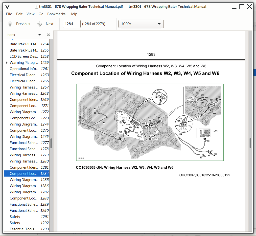
Component Location of Wiring Harness W2, W3, W4, W5 and W6
Wiring Diagram of Wiring Harness and Road Lights W2, W5 and W6
Wiring Diagram of MAXICUT Precutter Wiring Harness W3 — Baletrak (S.N. 070408—088999)
Wiring Diagram of Rear Road Lights W4 — BaleTrak (S.N. 070408—088999)
Component Location and Wiring Diagram of Battery Wiring Harness W1
Functional Schematic (Part 1) — BaleTrak (S.N. 070408—088999)
Functional Schematic (Part 2) — Baletrak (S.N. 070408—088999)
Group 30B: Diagnostic Modes/BaleTrak Control
Safety
Essential Tools
Diagnostic Mode: User Parameters
Channel 001: Reset to Factory Default Settings
Channel 002, 003, 004
Channel 005: Not Used
Channel 006 and 007: Calibration of Bale Shape Potentiometer
Channel 008: Measurement units
Channel 009
Channel 010, 011: Not Used
Channel 012: Test of Net Cut Switch (S.N. —079999)
Channel 012: Test of Net Cut Sensor (S.N. 080000—)
Channel 013: Test of Full-Size Bale Switch
Channel 014: Test of Oversize-Gate Switch
Channel 015, 016: Not Used
Channel 017: Speed of Gear Case
Channel 018: Test of Actuator Current Consumption
Channel 019: Voltmeter
Channel 020: Test of LCD Screen
Channel 021: Maximum Actuator Current Consumption
Channel 022: Test of Twine Pulley Sensor 1
Channel 023: Test of Twine Pulley Sensor 2
Channel 024: Test of MaxiCut MaxiCut is a trademark of Deere & Company Precutter Reverse Sensor
Channel 025: Test of MaxiCut MaxiCut is a trademark of Deere & Company Precutter Knife Switches
Channel 026, 027, 028: Not Used
Channel 029: Calibration of Double Arm Twine Tying Actuator
Channel 030: Twine Actuator Stroke
Channel 031: Not used
Channel 032
Diagnostic Mode: Factory Parameters
Channel 201: Baler Model
Channel 202: Twine Tying Device
Channel 203: Net Tying Mode Configuration
Channel 204: Not Used
Channel 205: Gear Case RPM Sensor
Channel 206: Not Used
Channel 207: Calibration of Gear Case RPM Sensor
Channel 208: Not Used
Channel 209: MaxiCut MaxiCut is a trademark of Deere & Company Precutter Device
Channel 210: Twine Pulley Sensors
Channel 211: Bale Shape Device
Channel 212 : Adjust Speed of Net Actuator
Channel 213 : Adjust Drop-Off Time of Net Actuator
Channel 214 : Adjust Acceleration Ramp of Net Actuator
Diagnostic Mode: Diagnostic Channels
Channel 301/3/5 and 302/4/6: Diagnostic Trouble Code (DTC) and Bale Counter Memory
Channel 307: Minutes Counter
Channel 308: Global Hours Counter
Channel 309: Lowest Battery Voltage Level Recorded
Channel 310: Highest Battery Voltage Level Recorded
Channel 311: Controller Software Version
Channel 312: Total Bale Counter
Group 40: Electrical System/GreenStar Control
GreenStar Monitor
GreenStar Monitor Board Description
INFO Mode Functions
RUN Mode Functions (Factory Settings)
Wrapping Process Description with GreenStar Control
Position Wrapping Arms to Start a Wrapping Cycle
Position Wrapping Table to Start a Wrapping Cycle
Group 40A: Electrical Diagrams/GreenStar Control
Section Identification in Functional Schematics
Wiring Harness Identification
Component Identification — GreenStar
Component Location of Main and Auxiliary Wiring Harnesses W101, W102, W104 and W110
Wiring Diagram of Main and Auxiliary Wiring Harnesses W101, W102, W104 and W110
Component Location of Sensor and Switch Wiring Harnesses W103, W105, W106, W107, W108, W109, W111 and W112
Wiring Diagram of Sensor and Switch Wiring Harnesses W103, W105, W106, W107, W108, W109, W111 and W112 (S.N. —079999)
Wiring Diagram of Sensor and Switch Wiring Harnesses W103, W105, W106, W107, W108, W109, W111 and W112 (S.N. 080000—)
Component Location of GreenStar Cab Harness W113
Wiring Diagram of Greenstar Cab Harness W113
Functional Schematic (Part 1)
Functional Schematic (Part 2)
Functional Schematic (Part 3)
Functional Schematic (Part 4) (S.N. —079999)
Functional Schematic (Part 4) (S.N. 080000—)
Functional Schematic (Part 5) (S.N. —079999)
Functional Schematic (Part 5) (S.N. 080000—)
Functional Schematic (Part 6)
Group 40B: Diagnostic Mode/GreenStar Control
Enter Diagnostic Functions (GreenStar)
Enter Recent Problem List (GreenStar)
Test Sensors (GreenStar)
Test Electro-Hydraulic Components (GreenStar)
Group 40C: Machine Setup/GreenStar Control
Enter Machine Settings (GreenStar)
SETUP Mode Functions
Enter Machine Setup Pages
SETUP Machine Mode Functions
Set Knife Timing
Set Slow Speed Distances
Set Table Transfer Distances
Set Gate Delay
Set Bale Ejection Timing
Set Gate Close Pressure Timing
Set Sender Parameters (S.N. —068999)
Set Sender Parameter (S.N. 070000— )
Select Slow Arms at Film Release
Set Knife Raising
Select 50/50 Valve Option
Set Default Values
Group 40D: Software/GreenStar Control
Software Version
Loading New Wrapping Baler Software
Loading Wrapping Baler Software Language
Group 40I: Checking GreenStar Electrical Power System
Theory of operation
Checking Greenstar Electrical Power System
Group 40J: Fuse Diagnosis
Fuse Diagnosis
Group 40K: Checking Lamp E101 (Optional)
Theory of operation
Component Identification
Check Lamp E101 (optional)
Functional Schematic of Lamp E101 (Optional)
Group 40L: Checking Safety Arm Sensor S103 and Stop Button S101
Theory of operation
Component Identification
Check Safety Arm Sensor S103 and Stop Button S101
Functional Schematic of Safety Arm Sensor S103 and Stop Button S101
Group 40M: Checking Torn Film Sensor S104
Theory of operation
Component Identification
Check Torn Film Sensor S104
Functional Schematic of Torn Film Sensor S104
Group 40N: Checking Wrapping Arm Position Sensor S105
Theory of operation
Component Identification
Check Wrapping Arm Position Sensor S105
Functional Schematic of Wrapping Arm Position Sensor S105
Group 40O: Checking Wrapping Arm Rotation Sensor S106
Theory of operation
Component Identification
Check Wrapping Arm Rotation Sensor S106
Functional Schematic of Wrapping Arm Rotation Sensor S106
Group 40P: Checking Net Feeding Sensor S107
Theory of operation
Component Identification
Check Net Feeding Sensor S107 (S.N. —079999)
Functional Schematic of Net Feeding Sensor S107 (S.N. —079999)
Functional Schematic of Net Feeding Sensor S107 (S.N. 080000—088999)
Group 40Q: Checking Gate Open Sensor S108
Theory of operation
Component Identification
Check Gate Open Sensor S108
Functional Schematic of Gate Open Sensor S108
Group 40R: Checking Gate Closed Sensor S109
Theory of operation
Component Identification
Check Gate Closed Sensor S109
Functional Schematic of Gate Closed Sensor S109
Group 40S: Checking Bale On Table Sensor S110
Theory of operation
Component Identification
Check Bale On Table Sensor S110
Functional Schematic of Bale On Table Sensor S110
Group 40T: Checking Wrapping Table Position Sensors S111 and S112
Theory of operation
Component Identification
Check Wrapping Table Position 1 Sensor S111
Check Wrapping Table Position 2 Sensor S112
Functional Schematic of Wrapping Table Position 1 and 2 Sensors S111 and S112
Group 40V: Checking Table Positioning Sensor S113
Theory of operation
Component Identification
Check Table Positioning Sensor S113
Functional Schematic of Table Positioning Sensor S113
Group 40W: Checking Twine Tying Sensor S114 and Net Cut Sensor S4
Theory of operation
Component Identification
Check Net Cut Switch S4 (S.N. —079999)
Check Twine Tying Sensor S114
Functional Schematic of Twine Tying Sensor S114 and Net Cut Switch S4 (S.N. —079999)
Functional Schematic of Twine Tying Sensor S114 and Net Cut Sensor S4 (S.N. 080000—088999)
Group 40X: Checking Slow Speed Table Belt solenoid valve Y101 (Optional)
Theory of operation
Component Identification
Check Slow Speed Table Belt Rotation solenoid valve Y101
Functional Schematic of Slow Speed Table Belt Rotation Electrovalve Y101
Group 40Y: Checking solenoid valve Y102 for Lowering Knives
Theory of operation
Component Identification
Check solenoid valve Y102 for Lowering Knives
Functional Schematic of Electrovalve Y102 for Lowering Knives
Group 40Z: Checking solenoid valve Y103 for Raising Knives
Theory of operation
Component Identification
Check solenoid valve Y103 for Raising Knives
Functional Schematic of Electrovalve Y103 for Raising Knives
Group 40AA: Checking Close Gate solenoid valve Y104
Theory of operation
Component Identification
Check Close Gate solenoid valve Y104
Functional Schematic of Close Gate Electrovalve Y104
Group 40AB: Checking Open Gate solenoid valve Y105
Theory of operation
Component Identification
Check Open Gate solenoid valve Y105
Functional Schematic of Open Gate Electrovalve Y105
Group 40AC: Checking Table Forward Movement solenoid valve Y106
Theory of operation
Component Identification
Check Table Forward Movement solenoid valve Y106
Functional Schematic of Table Forward Movement Electrovalve Y106
Group 40AD: Checking Table Backward Movement solenoid valve Y107
Theory of operation
Component Identification
Check Table Backward Movement solenoid valve Y107
Functional Schematic of Table Backward Movement Electrovalve Y107
Group 40AE: Checking Fast Speed Arm Rotation solenoid valve Y108
Theory of operation
Component Identification
Check Fast Speed Arm Rotation solenoid valve Y108
Functional Schematic of Fast Speed Arm Rotation Electrovalve Y108
Group 40AF: Checking Reverse Arm Rotation solenoid valve Y109
Theory of operation
Component Identification
Check Reverse Arm Rotation solenoid valve Y109
Functional Schematic of Reverse Arm Rotation Electrovalve Y109
Group 40AG: Checking Regular Arm Rotation solenoid valve Y110
Theory of operation
Component Identification
Check Regular Arm Rotation solenoid valve Y110
Functional Schematic of Regular Arm Rotation Electrovalve Y110
Group 40AH: Checking Slow Speed Table Movement solenoid valve Y111 and Buzzer H101
Theory of operation
Component Identification
Check Slow Speed Table Movement solenoid valve Y111 and Buzzer H101
Functional Schematic of Slow Speed Table Movement Electrovalve Y111 and Buzzer H101
Group 50: Electrical System/Virtual Terminal Control
Main Page Display Description
Softkey Designation
Counter Function
Wrapping Process Description with Virtual Terminal Control
Place Wrapping Arms in Home Position
Place Wrapping Table in Home Position
Group 50A: Electrical Diagrams/Virtual Terminal Control
Section Identification in Functional Schematics — Virtual Terminal
Wiring Harness Identification—Virtual Terminal
Component Identification — Virtual Terminal
Component Location of Main and Auxiliary Wiring and Road Lights Harnesses W5, W6, W7, W101 and W107 (Right-Hand Side View)
Component Location of Main and Auxiliary Wiring and Road Lights Harnesses W101, W103, W105, W106, W110, W111 and W112 (Left-Hand Side View)
Wiring Diagram of Wiring and Road Lights Harnesses W7, W101, W107 and W110 (Part 1)
Wiring Diagram of Wiring and Road Lights Harnesses W7, W101, W107 and W110 (Part 2)
Wiring Diagram of Wiring and Road Lights Harnesses W103, W105, W106, W111 and W112
Component Location of MaxiCut MaxiCut is a trademark of Deere & Company Precutter Wiring Harness W3 (S.N. 089000—)
Wiring Diagram of MaxiCut MaxiCut is a trademark of Deere & Company Precutter Wiring Harness W3 (S.N. 089000—)
Component Location of Virtual Terminal Cab Harness W113
Wiring Diagram of Virtual Terminal Cab Harness W113
Functional Schematic (Part 1) — Virtual Terminal
Functional Schematic (Part 2) — Virtual Terminal
Functional Schematic (Part 3) — Virtual Terminal
Functional Schematic (Part 4) — Virtual Terminal
Functional Schematic (Part 5) — Virtual Terminal
Functional Schematic (Part 6) — Virtual Terminal
Group 50B: Diagnostic Mode/Virtual Terminal Control
Access Diagnostic Functions
Diagnostic Function
Recent Problems List
Test Tractor Battery Voltage
Test Sensors
Test Electro-Hydraulic Components
Test Actuator Electrical Consumption
Group 50C: Machine Setup/Virtual Terminal Control
Access Machine Settings
Setting Function
Enter Advanced Machine Settings
Advanced Machine Setting Function
Set Wrapping Knife Opening
Set Table Transfer Distance
Set Baler Rotation Speed Pulses
Set Tying Device
Set Auto Lube Device
Set Wrapping Table Sensor Parameters
Set Bale Rotation Speed
Set Default Values
Run Continuous
Set Wrapping Table Transfer Parameters
Set Wrapping Arm Speed Parameters
Calibration of Twine Actuator
Calibration of Net Actuator
Group 50D: Software/Virtual Terminal Control
Software Version
Section 250: Lubrication System — Operation and Tests
Group 05: Chain Lubrication — Theory of Operation
Chain Lubrication — Theory of Operation — Summary of References
Group 05A: Chain Lubrication — Theory of Operation (S.N. —049999)
Automatic Lubrication System (S.N. —049999)
Lubrication System Pump (S.N. —049999)
Main Oil Reservoir
Metering Valve
Group 05B: Chain Lubrication — Theory of Operation (S.N. 050000—)
Automatic Lubrication System
Lubrication System Pump
Group 06: Chain Lubrication — Component Location
Chain Lubrication — Component Location — Summary of References
Group 06A: Chain Lubrication — Component Location (S.N. —049999)
Brief Description
Component Location for Pickup With MaxiCut MaxiCut is a trademark of Deere & Company Precutter (S.N. —049999)
Group 06B: Chain Lubrication — Component Location (S.N. 050000—)
Component Location for Pickup With MaxiCut MaxiCut is a trademark of Deere & Company Precutter
Group 07: Chain Lubrication — Troubleshooting
Chain Lubrication — Troubleshooting — Summary of References
Group 07A: Chain Lubrication — Troubleshooting (S.N. —049999)
Diagnose Malfunctions
Group 07B: Chain Lubrication — Troubleshooting (S.N. 050000—)
Diagnose Chain Oil Malfunctions
Group 08: Chain Lubrication — Diagnostic and Test Procedure (S.N. —049999)
Test Sequence
Group 20: Automatic Greasing System — Theory of Operation
Automatic Greasing System—Principle
Group 22: Automatic Greasing System — Troubleshooting
Automatic Greasing System—Troubleshooting
Group 23: Automatic Greasing System — Diagnostic and Test Procedure
Check Automatic Greasing System
Section 260A: Air Brake System — Operation and Tests
Group 05: Safety
Working on the Air Brake System
Group 20: Air Brake System — Description
Description and Diagram
Group 21: Air Brake System — Tests
Essential Tools
Specifications
Operational Check
Check for Leaks at Brake Circuit
Check the Braking Pressure
Check Pilot Line Pressure
Section 260B: Hydraulic Brake System — Operation and Tests
Group 05: Safety
Safety - Avoid High-Pressure Fluids
Wear Protective Clothing
Group 20: Hydraulic Brake System — Description
Description and Diagram
Group 21: Hydraulic Brake System — Tests
Check the Braking Pressure
Section 270: Hydraulic System — Operation and Tests
Group 05: Safety
Recommendations
Group 10: General Information
Hydraulic Symbols (As Defined by ISO 1219)
Group 15: MaxiCut Precutter Hydraulic System — Description
Pickup Attachment and MAXICUT MAXICUT is a trademark of Deere & Company Precutter System
Description and Diagram
Group 16: MaxiCut Precutter Hydraulic System — Tests
MaxiCut Precutter Hydraulic System — Tests - Essential or Recommended Tools
MaxiCut Precutter Hydraulic System — Tests - Specifications
Check Pickup Lift Function
Check Gear Case Reverser Function
Check Knife Function
Check Solenoid Valve Function
Group 20: Main Control Valve — Description
Main Control Valve — Description — Summary of References
Group 20A: Main Control Valve — Description (S.N. —088999)
Description and Diagram of Main Control Valve (S.N. —088999)
Group 20B: Main Control Valve — Description (S.N. 089000—)
Description and Diagram of Main Valve Control
Group 25: Bale Density/Gate Control — Description
Bale Density/Gate Control — Description — Summary of References
Group 25A: Bale Density/Gate Control — Description (S.N. —088999)
Bale Density/Gate Control — Specifications
Description and Diagram of Bale Density/Gate Control (S.N. —088999)
Starting a Bale
During Baling (S.N. —088999)
Opening the Gate
Closing the Gate
Group 25B: Bale Density/Gate Control — Description (S.N. 089000—)
Bale Density/Gate Control — Description (S.N. 089000—) — Specifications
Description and Diagram of Bale Density Control Valve
Component Description
Start a Bale
During Baling
Open the Gate
Close the Gate
Group 26: Bale Density/Gate Control — Tests
Bale Density/Gate Control — Tests — Summary of References
Group 26A: Bale Density/Gate Control — Tests (S.N. —088999)
Essential Tools (S.N. —088999)
Specifications (S.N. —088999)
Check Bale Density Hydraulic System (S.N. —088999)
Check Gate Operation Hydraulic System (S.N. —088999)
Check Bale Density Gauge
Check Bale Density Adjustable Relief Valve and Check Valve
Check Valve Pilot Piston Check
Check Safety Relief Valve
Check Hydraulic Cylinder for Leakage
Check Gate Lock Valve for Leakage
Group 26B: Bale Density/Gate Control — Tests (S.N. 089000—)
Bale Density/Gate Control — Tests (S.N. 089000—) — Essential or Recommended Tools
Bale Density-Gate Control — Tests (S.N. 089000—) — Specifications
Check Bale Density Hydraulic System
Check Gate Operation Hydraulic System
Check Bale Density Gauge (S.N. 089000—)
Check Bale Density Adjustable Relief Valve and Check Valve (S.N. 089000—)
Check Gate Pilot-operated Valves
Check Hydraulic Cylinder for Leakage (S.N. 089000—)
Group 30: Wrapping System — Description
Wrapping System — Description — Summary of References
Group 30A: Wrapping System — Description (S.N. —088999)
Description and Diagram — Wrapping System Control
Group 30B: Wrapping System — Description (S.N. 089000—)
Description and Diagram of Wrapping System Control
Section 330A: Net Tying — Operation and Tests
Group 05: Troubleshooting
Standard Net Tying Device Difficulties
CoverEdge Net Tying Device Difficulties
Group 10: Theory of Operation
How the Net Tying Works
Section 330B: Twine Tying — Operation and Tests
Group 05: Troubleshooting
Troubleshooting
Section 399: Special Tools — Dealer-Fabricated
Group 05: Manufacturing the Tools
OMP Hydraulic Motor Seal Installer
OMS Hydraulic Motor Seal Installer
John Deere Hay and Forage Wrapping Balers Models 678 Diagnosis and Repair Service Manual (TM3301)
![]()