
John Deere Hay and Forage Round Balers 568, 578 Diagnosis and Repair Service Technical Manual (TM3300)
Complete Diagnosis and Repair manual with electrical wiring diagrams for John Deere Hay and Forage Round Balers Models 568 and 578, with all the shop information to maintain, diagnose, repair,rebuild like professional mechanics.
John Deere 568 and 578 Hay and Forage Round Balers workshop Diagnosis and Repair manual includes:
* Numbered table of contents easy to use so that you can find the information you need fast.
* Detailed sub-steps expand on repair procedure information
* Numbered instructions guide you through every repair procedure step by step.
* Troubleshooting and electrical service procedures are combined with detailed wiring diagrams for ease of use.
* Notes, cautions and warnings throughout each chapter pinpoint critical information.
* Bold figure number help you quickly match illustrations with instructions.
* Detailed illustrations, drawings and photos guide you through every procedure.
* Enlarged inset helps you identify and examine parts in detail.
TM3300 - John Deere Hay and Forage Round Balers 568, 578 Technical Manual (Diagnosis Operation Test Repair Service).PDF
TM3300 - John Deere Hay and Forage Round Balers 568, 578 Technical Manual (Diagnosis Operation Test Repair Service).EPUB
tm3310 - 568 and 578 Round Balers Teknisk håndbok.pdf
tm3310 - 568 and 578 Round Balers Teknisk håndbok.epub
Total Pages: 908 pages
File Format: PDF/EPUB/MOBI/AZW (PC/Mac/Android/Kindle/iPhone/iPad; bookmarked, ToC, Searchable, Printable)
Language: English / Norwegian
MAIN SECTIONS
Foreword
Safety
Safety Information
General
Serial Numbers
Torques for Hardware
Lubrication
Electrical System - Repair
Connectors
Sensors and Switches
Actuators
ELS (Manual Twine Control Switch)
ELC Plus Monitor (Electronic Tying Control)
BaleTrak and BaleTrak Plus Monitor
Power Train
Walterscheid Powerline
Shear Bolt System
Cam-Type Cut Out Clutch (S.N. -06XXXX)
Cam-Type Cut Out Clutch (S.N. 06XXXX-)
Gear Case (w/o Precutter)
Precutter Gear Case
Chain Tension
Sprocket Alignment
Braking System - Repair
Air Brakes
Hydraulic Brakes
Brake Shoe and Drum
Hydraulic System - Repair
General Information
Bale Density Control Valve
Hydraulic Cylinders
Precutter or MAXICUT Precutter Electro-Hydraulic Valve
Miscellaneous
Wheel Hub Repair
Bale Shape Indicator
Tongue
Lubrication System (S.N. -049999) - Repair
Drive Chain Lubrication
Lubrication System (S.N. 050000- ) - Repair
Drive Chain Lubrication
Pickup Repair
2.00 m (6 ft 7 in.) Pickup with Rotary Feeder and Precutter Device
Precutter System
Bale Chamber Rolls
Net Tying
Twine Tying Repair
Diagnostic Trouble Code For BaleTrak Control
Description
Battery Voltage
Twine Actuator M1
Net Actuator M2
Pickup Valve Y4
Knife Valve Y3
Reverser Valve Y2
Gear Case RPM Sensor S6
Twine Pulley Sensor S7/S8
Net Switch S4
Right Gate Switch S1
Full-Size Bale Switch S3
EPROM
Electrical System
General Information
Test Equipment
Electrical System Diagrams for Road Light
Electrical Diagram / Battery Wiring Harness
Electrical System / ELS (Manual Twine Control)
Electrical Diagram / ELS
Checking Twine Tying Function
Electrical System / ELC (S.N. -029999)
Electrical Diagram / ELC (S.N. -029999)
Checking Twine/Net Tying Function
Electrical System / ELC (S.N. 030000-)
Electrical Diagram / ELC (S.N. 030000-)
Electrical System / BaleTrak Control
Electrical Diagram / BaleTrak Control
Diagnostic Modes
Lubrication System - Operation and Tests
Air Brake System - Operation and Tests
Hydraulic Brake System - Operation and Tests
Hydraulic System - Operation and Tests
Bale Density / Gate Control - Description
Bale Density / Gate Control - Troubleshooting
Bale Density / Gate Control - Tests
Pickup Lift System (Baler without Precutter)
Pickup with Reversible Rotary Feeder
Precutter or MAXICUT Precutter Hydraulic System - Description
Precutter or MAXICUT Precutter Hydraulic System - Tests
Net Tying - Operation and Tests
Twine Tying - Operation and Tests
Special Tools - Dealer-Fabricated
tm3300 - 568 and 578 Round Balers
Table of Contents
Foreword
Section 05: Safety
Group 05: Safety Information
Prepare for Emergencies
Service Machine Safely
Avoid High-Pressure Fluids
Support Machine Properly
Wear Protective Clothing
Stay Clear of Rotating Drivelines
Service Machines Safely
Work in Clean Area
Remove Paint Before Welding or Heating
Avoid Heating Near Pressurized Fluid Lines
Illuminate Work Area Safely
Replace Safety Signs
Use Proper Lifting Equipment
Service Tires Safely
Practice Safe Maintenance
Use Proper Tools
Dispose of Waste Properly
Live With Safety
Safety Information - Air Brake System
Section 10: General
Group 10: Serial Numbers
Baler Identification Number
Serial Number Plate Description
Group 15: Torques for Hardware
Metric Bolt and Screw Torque Values
Group 20: Lubrication
Gear Oil
Grease
Multiluber Chain Oil
Section 40: Electrical System — Repair
Group 05: Connectors
Special or Essential Tools
Electrical Connector Handling
Disconnect the Electrical Circuit
Insulated and Non-Insulated Connectors
Replacing Small MATE-N-LOK MATE-N-LOK is a trademark of AMP, Inc. Contacts in Connector Housings
Replacing SURE-SEAL SURE-SEAL is a trademark of ITT Cannon Electric. Connector Bodies
Replace CPC, Large MATE-N-LOK and METRIMATE CPC, MATE-N-LOK, and METRIMATE are trademarks of AMP Inc. Pin Type Connectors
Replacing DEUTSCH DEUTSCH is a trademark of Deutsch Co. Connectors
Install DEUTSCH DEUTSCH is a trademark of the Deutsch Co. Contact
Replace WEATHER PACK WEATHER PACK is a trademark of Packard Electric. Connector
Weather Pack Weather Pack is a trademark of Packard Electric. Male and Female Terminal
Replacing Metri Pack Metri Pack is a trademark of Delphi Packard Electric Systems. Connectors For Metri Pack connectors, 150 series
Replacing SCHLEMMER SCHLEMMER is a trademark of Josef Schlemmer GmbH. Connectors
Harness Repair (Splice Broken or Cut Wire)
Harness Repair—Splice Connector
Group 10: Sensors and Switches
Specifications
Component Identification
Adjusting Oversize/Gate Switch S1 (Baler With BaleTrak Control Monitor)
Adjusting Full-Size Bale Switch S1 (Baler With ELC Monitor) — S3 (Baler With BaleTrak Control Monitor)
Adjusting Net Cut Switch S2 (Baler With ELC Monitor) — S1 (Baler With BaleTrak Control Monitor)
Adjusting Baler Speed Sensor S6 (Baler With BaleTrak Control Monitor)
Adjusting Twine Pulley Sensors S7 and S8 (Baler With BaleTrak Control Monitor and Single Arm Twine Tying)
Adjusting Twine Pulley Sensors S7 and S8 (Baler With BaleTrak Control Monitor and Double Arm Twine Tying)
Adjusting Precutter and MAXICUT Precutter Reverse Sensor S9 (578 With Precutter)
Precutter and MAXICUT Precutter Knife Switches S10 and S11
Group 15: Actuators
Other Material
Specifications
Component Identification
Remove and Install Twine Arm Actuator M1
Disassemble/Assemble Twine Actuator M1 and Net Actuator M2
Group 30: ELS (Manual Twine Control Switch)
Manual Twine Control Switch
Group 40: ELC Plus Monitor (Electronic Tying Control)
Set Monitor for Tying Arm Type
Group 50: BaleTrak and BaleTrak Plus Monitor
Replace BaleTrak EPROM
Disassembling BaleTrak Monitor
Assembling BaleTrak Monitor
Reprogramming BaleTrak Software
Section 50: Power Train
Group 10: Walterscheid Powerline
Specifications
Exploded-view of Powerline
Repair Powerline
Group 15: Shear Bolt System
Repair
Group 20: Cam-Type Cut Out Clutch (S.N. —06XXXX)
Other Material
Specifications
Disassembling Cam-Type Cut Out Clutch
Adjust Cam-Type Cut Out Clutch (S.N. -06XXXX)
Exploded View of Cam-Type Cut Out Clutch
Assembling Cam-Type Cut Out Clutch
Group 21: Cam-Type Cut Out Clutch (S.N. 06XXXX—)
Other Material
Specifications
Disassemble Cam-Type Cut Out Clutch
Adjust Cam-Type Cut Out Clutch (S.N. 06XXXX-)
Exploded View of Cam-Type Cut Out Clutch
Assembling Cam-Type Cut Out Clutch
Group 25: Gear Case (w/o Precutter)
Essential Tools
Other Material
Specifications
Disassemble Gear Case
Inspect Gear Case
Assemble Gear Case
Install Gear Case
Group 30: Precutter Gear Case
Other Material
Specifications
Removing Gear Case
Exploded View of Precutter Gear Case
Disassemble Gear Case
Inspect Gear Case
Assemble Gear Case
Install Gear Case
Group 35: Chain Tension
Adjusting Roll Drive Chains
Adjusting 2.00 m (6 ft 6.7 in.) Pickup Drive Chains (Without Precutter Device)
Adjust Drive Chains for 2.00 m (6 ft. 6.7 in.) Pickup with Precutter or MAXICUT Precutter
Adjust 2.00 m (6 ft. 6.7 in.) Precutter and MAXICUT Precutter Main Drive Chain
Group 40: Sprocket Alignment
Specifications
Checking and Adjusting Sprocket Alignment
Section 60: Braking System — Repair
Group 05: Air Brakes
Specifications
Preliminary Check
General Information
Drain Air Brake Reservoir
Air Brake Connection Lines—Exploded View
Clean Air Filters
Install Plug-in Connections
Remove Reservoir
Install Reservoir
Remove Relay Emergency Valve
Install Relay Emergency Valve
Remove Brake Cylinder
Adjust Air Brake Cylinder Clevis
Install Brake Cylinder
Group 10: Hydraulic Brakes
Specifications
Hydraulic Brake Cylinders
Remove Brake Cylinder
Adjust Hydraulic Brake Cylinder Clevis
Install Brake Cylinder
Group 15: Brake Shoe and Drum
Specifications
Adjust Brake Shoes
Adjust Brake Lever
Section 70: Hydraulic System — Repair
Group 05: General Information
Avoid High-Pressure Fluids
General Repair Information
Install Inline Orifice
Group 10: Bale Density Control Valve
Remove and Install Bale Density Control Valve
Disassembling Bale Density Control Valve
Assemble Bale Density Control Valve
Checking Condition of Valve Seats and Poppets
Adjusting Bale Density Control Valve
Group 15: Hydraulic Cylinders
Other Material
Specifications
Removing and Installing Gate Cylinder
Disassembling and Assembling Gate Cylinder
Disassembling and Assembling 2.00 m (6 ft 6.7 in.) Pickup Lift Cylinder
Disassembling and Assembling 2.00 m (6 ft 7 in.) Pickup Lift Cylinder (Baler with Precutter or MAXICUT MAXICUT is a trademark of Deere & Company Precutter) (S.N. —040844)
Disassemble and Assemble 2.00 m (6 ft 7 in.) Pickup Lift Cylinder (Baler with Precutter or MAXICUT Precutter) (S.N. 040845— )
Disassemble and Assemble Precutter and MAXICUT Precutter Knife Cylinder
Disassemble and Assemble Gear Case Reverser Cylinder
Group 40: Precutter or MAXICUTMAXICUT is a trademark of Deere & Company Precutter Electro-Hydraulic Valve
Specifications
Remove and Install Precutter and MAXICUT Precutter Valve
Bleed Precutter and MAXICUT Precutter Hydraulic Circuit
Identification View of Precutter and MAXICUT Precutter Valve
Disassemble and Assemble Precutter and MAXICUT Precutter Valve
Section 80: Miscellaneous
Group 05: Wheel Hub Repair
Specifications
Exploded View of Wheel Hub (without Brake)
Disassemble Wheel Hub (without Brake)
Assemble Wheel Hub (without Brake)
Exploded View of Wheel Hub (with Brake)
Disassemble Wheel Hub (with Brake)
Assemble Wheel Hub (with Brake)
Group 10: Bale Shape Indicator
Adjust Bale Shape Indicator Strap
Group 15: Tongue
Specifications
Assemble Tongue
Section 85A: Lubrication System (S.N. —049999) — Repair
Group 05: Drive Chain Lubrication
Removing and Installing Filter
Remove and Install Metering Valve
Disassemble and Assemble Pump
Adjust Lubrication Pump Flow
Adjust Chain Oiling System Brush Flow
Adjusting Brush
Bleeding the Circuit
Section 85B: Lubrication System (S.N. 050000— ) — Repair
Group 05: Drive Chain Lubrication
Adjust Oil Flow
Bleeding Chain Oiling System Pump
Adjusting Brushes
Removing and Installing Hoses
Section 100A: Pickup Repair
Group 15: 2.00 m (6 ft 7 in.) Pickup with Rotary Feeder and Precutter Device
Specifications
Repair the Pickup Drum
Section 100B: Precutter System
Group 05: Adjustment
Specifications
Precutter Rotor and Bearing - Cross-Sectional View
MAXICUT Precutter Rotor and Bearing - Cross-Sectional View
Adjusting Scrapers
Section 120: Bale Chamber Rolls
Group 20: Rolls and Bearings
Other Material
Specifications
Service Rolls Safely
Baler Roll Numbering
Rolls and Bearings - Cross-Sectional View
Removing Roll No. 1 and its Bearings
Removing Roll No. 2 to 9 and their Bearings
Removing Roll No.10 and its Bearings
Removing Roll No.11, 14, 17 and their Bearings
Removing Roll No.12 and its Bearings
Removing Roll No.13, 15, 16 and their Bearings
Install Roll No. 1 and its Bearings
Install Rolls No. 2 to 9 and their Bearings
Install Rolls No. 10, 11, 14, 17 and their Bearings
Install Roll No. 12 and its Bearings
Install Rolls No. 13, 15, 16 and their Bearings
Section 130A: Net Tying
Group 15: Repair
Specifications
Exploded View of Net Tying System
Disassembling Net Tying System
Assemble Net Tying System
Replacing Bearings in Roll
Removing and Installing Net Knife
Sharpening Net Knife
Removing and Installing Rear Net Guide
Remove Front Net Guide
Installing Front Net Guide
Removing Net Feed Roll Drive Belt
Install Net Feed Roll Drive Belt
Removing Net Wrapped Around Feed Rolls
Check and Adjust Galvanized Net Feed Roll No. 18 Radial Play
Check and Adjust Galvanized Net Feed Roll No. 18 Bearing
Adjust Net Feed Roll Pressure
Adjust Net Knife Arm Stop
Adjust Net Feed Roll Drive Belt Tension
Check Net Feed Roll Brake
Adjusting Net Lateral Guide
Section 130B: Twine Tying
Group 10: Repair (Single Arm Twine Tying)
Specifications
Exploded View of Twine Tying System
Adjust Twine Guide
Adjusting Twine Cutter Anvil
Adjust Twine Arm Travel (Except With BaleTrak Control Monitor)
Adjust Twine Arm Re-extension Point (Baler with ELC/ELC Plus Monitor and Single Arm Twine Tying)
Adjust Arm Twine Tying Starting Point (Baler with BaleTrak Control)
Group 15: Repair (Double Arm Twine Tying)
Specifications
Exploded View of Twine Tying System
Adjusting Double Arm Twine Tying Geometry
Adjust Double Arm Twine Tying Starting Point
Adjusting Flaps
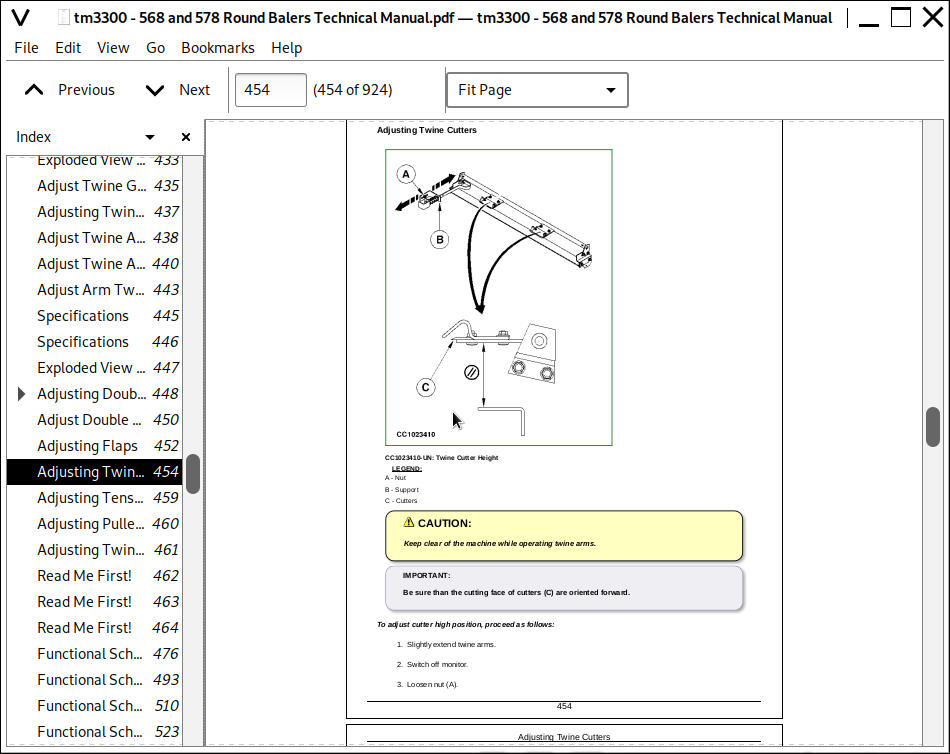
Adjusting Twine Cutters
Adjusting Tension Plates
Adjusting Pulley Supports
Adjusting Twine Guides
Section 211: Diagnostic Trouble Code For BaleTrak Control
Group 05: Description
Read Me First!
Group E00X: Battery Voltage
E001 - Erratic Supply Voltage
E002 - Tension Below or Equal to 11.2 V
E003 - Tension Over or Equal to 16 V
Functional Schematic of Power Supply
Group E20X: Twine Actuator M1
E201 - Open Circuit
E202 - Faulty Actuator
E203 - Resistive Power Line
E204 - Shorted Circuit
E205 - Grounded Circuit
Functional Schematic of Twine Tying Actuator M1
Group E21X: Net Actuator M2
E211 - Open Circuit
E212 - Faulty Actuator
E213 - Resistive Power Line
E214 - Shorted Circuit
E215 - Grounded Circuit
Functional Schematic of Net Tying Actuator M2
Group E23X: Pickup Valve Y4
E231 - Open Circuit
E232 - Grounded Circuit
E233 - Shorted Circuit
Functional Schematic of Pickup Valve Function Y4
Group E24X: Knife Valve Y3
E241 - Open Circuit
E242 - Grounded Circuit
E243 - Shorted Circuit
Functional Schematic of Knife Valve Function Y3
Group E25X: Reverser Valve Y2
E251 - Open Circuit
E252 - Grounded Circuit
E253 - Shorted Circuit
Functional Schematic of Reverser Valve Function Y2
Group E31X: Gear Case RPM Sensor S6
E311 - Open Circuit
E312 - Speed below the Minimum Value
E313 - Speed over the Maximum Value
Functional Schematic of Gear Case RPM Sensor S6
Group E32X: Twine Pulley Sensor S7/S8
E321 - Twine Not Detected
E322 - Twine Not Cut
Functional Schematic of Twine Pulley Sensors S7/S8
Group E40X: Net Switch S4
E401 - Always Opened
E402 - Always Closed
Functional Schematic of Net Switch S4
Group E41X: Right Gate Switch S1
E411 - Always Opened
E412 - Always Closed
Functional Schematic of Right Gate Switch S1
Group E43X: Full-Size Bale Switch S3
E432 - Always Closed
Functional Schematic of Full-Size Bale Switch S3
Group E60X: EPROM
E601 - User Table, All User Data Banks Corrupted
E602 - User Table, One User Data Bank Corrupted
E603 - Factory Table, All Factory Data Banks Corrupted
E604 - Factory Table, One Factory Bank Corrupted
E605 - EPROM or Software Failure
Section 240: Electrical System
Group 05: General Information
Read Me First!
Electrical Circuit Malfunctions
Open Circuit
Grounded Circuit
Shorted Circuit
How to Read a Functional Schematic
How to Read a Wiring and Harness Diagram
Symbols in System Diagrams
Component Identification Table
Group 06: Test Equipment
Special or Essential Tools
Group 10: Electrical System Diagrams for Road Light
Wiring Harness List
Component Identification
Component Location
Wiring Diagram
Group 14: Electrical Diagram / Battery Wiring Harness
Wiring harness identification
Component Identification
Component Location
Wiring Diagram
Group 15: Electrical System / ELS (Manual Twine Control)
Specifications
ELS (Manual Twine Control)
Operational Information
Group 15A: Electrical Diagram / ELS
Wiring Harness List
Component Identification
Component Location
Wiring Diagram
Group 15B: Checking Twine Tying Function
Theory of Operation
Identification
Functional Schematic of Twine Tying Function
Group 20: Electrical System / ELC (S.N. —029999)
Specifications
ELC (Electronic Tying Control Monitor) Description
Operational Information
Group 20A: Electrical Diagram / ELC (S.N. —029999)
Wiring Harness List
Component Identification
Component Location
Wiring Diagram of Main Wiring Harness W 2
Group 20B: Checking Twine/Net Tying Function
Theory of Operation
Identification
Functional Schematic of Twine/Net Tying Function
Group 25: Electrical System / ELC (S.N. 030000—)
Specifications
ELC Plus Monitor (Electronic Tying Control)
Operational Information
Group 25A: Electrical Diagram / ELC (S.N. 030000—)
Wiring Harness Identification (S.N. 030000—)
Component Identification
Component Location of Main Wiring Harness
Group 30: Electrical System / BaleTrak Control
Specifications
BaleTrak Monitor
BaleTrak Plus Monitor
BaleTrak Monitor Keyboard Description
BaleTrak Plus Monitor Keyboard Description
LCD Screen Description
Warning Pictograms
Operational Information
Group 30A: Electrical Diagram / BaleTrak Control
Electrical Diagram - BaleTrak Control - Summary of References
Sections Identification on Functional Schematics
Wiring Harness Identification (BaleTrak)
Component Identification
Component Location of Main Wiring Harness W2
Wiring Diagram of Main Wiring Harness W2
Component Location of Precutter Wiring Harness W3
Wiring Diagram of Precutter Wiring Harness W3
Functional Schematic (Part 1)
Functional Schematic (Part 2)
Group 30B: Diagnostic Modes
Safety
Essential Tools
Diagnostic Mode: User Parameters
Channel 001: Reset to Factory Default Settings
Channel 002, 003, 004
Channel 005, 006, 007: Not Used
Channel 008: Measurement units
Channel 009
Channel 010, 011: Not Used
Channel 012: Test of Net Cut Switch
Channel 013: Test of Full-Size Bale Switch
Channel 014: Test of Oversize-Gate Switch
Channel 015, 016: Not Used
Channel 017: Speed of Gear Case
Channel 018: Test of Actuator Current Consumption
Channel 019: Voltmeter
Channel 020: Test of LCD Screen
Channel 021: Maximum Actuator Current Consumption
Channel 022: Test of Twine Pulley Sensor 1 (S7)
Channel 023: Test of Twine Pulley Sensor 2 (S8)
Channel 024: Test of Precutter and MAXICUT Precutter Reverse Sensor (BaleTrak Plus Only)
Channel 025: Test of Precutter and MAXICUT Precutter Knife Switches (BaleTrak Plus Only)
Channel 026, 027, 028: Not Used
Channel 029: Calibration of Single Arm Twine Tying Actuator
Channel 029: Calibration of Double Arm Twine Tying Actuator
Channel 030: Twine Actuator Stroke
Channel 031: Adjusting Tying End Distance (Single Arm Tying)
Channel 032
Diagnostic Mode: Factory Parameters
Channel 201: Baler Model
Channel 202: Twine Tying Device
Channel 203: Net Tying Device
Channel 204: Not Used
Channel 205: Gear Case RPM Sensor
Channel 206: Not Used
Channel 207: Calibration of Gear Case RPM Sensor
Channel 208: Not Used
Channel 209: Precutter and MAXICUT Precutter
Channel 210: Twine Pulley Sensors
Diagnostic Mode: Diagnostic Channels
Channel 301/3/5 and 302/4/6: Diagnostic Trouble Code (DTC) and Bale Counter Memory
Channel 307: Minutes Counter
Channel 308: Global Hours Counter
Channel 309: Lowest Battery Voltage Level Recorded
Channel 310: Highest Battery Voltage Level Recorded
Channel 311: Controller Software Version
Channel 312: Total Bale Counter
Section 250A: Lubrication System - Operation and Tests (S.N. —049999)
Group 05: Theory of Operation
Automatic Lubrication System
Lubrication System Pump
Main Oil Reservoir
Metering Valve
Group 10: Component Location
Brief Description
Component Location for 2.00 m (6 ft 6.7 in.) Pickup
Component Location for Pickup With Precutter
Group 15: Troubleshooting
Diagnosing Malfunctions
Group 20: Diagnostic and Test Procedure
Test Sequence
Section 250B: Lubrication System - Operation and Tests (S.N. 050000— )
Group 05: Theory of Operation
Automatic Lubrication System
Lubrication System Pump
Group 10: Component Location
Component Location for 2.00 m (6 ft 7 in.) Pickup
Section 260A: Air Brake System - Operation and Tests
Group 05: Safety
Working on the Air Brake System
Group 20: Air Brake System - Description
Description and Diagram
Group 25: Air Brake System - Tests
Essential Tools
Specifications
Operational Check
Check for Leaks at Brake Circuit
Check the Braking Pressure
Check Pilot Line Pressure
Section 260B: Hydraulic Brake System - Operation and Tests
Group 20: Hydraulic Brake System - Description
Description and Diagram
Group 25: Hydraulic Brake System - Tests
Check the Braking Pressure
Section 270: Hydraulic System - Operation and Tests
Group 05: Safety
Recommendations
Group 10: General Information
Hydraulic Symbols (As Defined by ISO 1219)
Group 20: Bale Density / Gate Control - Description
Description and Diagram
Starting a Bale
During Baling
Opening the Gate
Closing the Gate
Group 21: Bale Density / Gate Control - Troubleshooting
Diagnosing Hydraulic Functions
Group 22: Bale Density / Gate Control - Tests
Essential Tools
Specifications
Check Bale Density Hydraulic System
Check Gate Operation Hydraulic System
Check Bale Density Gauge
Check Bale Density Adjustable Relief Valve and Check Valve
Check Valve Pilot Piston Check
Check Safety Relief Valve
Check Hydraulic Cylinder for Leakage
Check Gate Locking Valve for Leakage
Group 30: Pickup Lift System (Baler without Precutter)
2.00 m (6 ft 6.7 in.) Pickup — Identification and Diagram
Group 35: Pickup with Reversible Rotary Feeder
Description and Diagram
Group 40: Precutter or MAXICUTMAXICUT is a trademark of Deere & Company Precutter Hydraulic System - Description
Pickup Attachment (Baler with Precutter and MAXICUT MAXICUT is a trademark of Deere & Company Precutter)
Description and Diagram (Baler without BaleTrak Control Monitor)
Description and Diagram (Baler with BaleTrak Control Monitor)
Group 41: Precutter or MAXICUTMAXICUT is a trademark of Deere & Company Precutter Hydraulic System - Tests
Essential Tools
Specifications
Check Pickup Lift Function (Baler with Precutter and MAXICUT Precutter)
Check Gear Case Reverser Function (Baler with Precutter and MAXICUT Precutter)
Check Knife Function (Baler with Precutter and MAXICUT Precutter)
Check Electrovalve Function (Baler with Precutter and MAXICUT Precutter)
Section 330A: Net Tying - Operation and Tests
Group 05: Troubleshooting
Troubleshooting
Group 10: Theory of Operation
Net Tying Operation
Section 330B: Twine Tying - Operation and Tests
Group 05: Troubleshooting
Troubleshooting
Section 399: Special Tools — Dealer-Fabricated
Group 05: Manufacturing the Tools
Grooved Nut Spanner
John Deere Hay and Forage Round Balers 568, 578 Diagnosis and Repair Service Technical Manual (TM3300)
![]()