
John Deere Mower Conditioners Models 625, 630, 635, 830, 835 Repair Service Technical Manual (TM101419)

Complete service repair manual with electrical wiring diagrams for John Deere Mower Conditioners Models 625, 630, 635, 830 and 835, with all the workshop information to maintain, diagnose, repair, and rebuild like professional mechanics.
John Deere 625, 630, 635, 830 and 835 Mower-Conditioners workshop service & repair manual includes:
* Numbered table of contents easy to use so that you can find the information you need fast.
* Detailed sub-steps expand on repair procedure information
* Numbered instructions guide you through every repair procedure step by step.
* Troubleshooting and electrical service procedures are combined with detailed wiring diagrams for ease of use.
* Notes, cautions and warnings throughout each chapter pinpoint critical information.
* Bold figure number help you quickly match illustrations with instructions.
* Detailed illustrations, drawings and photos guide you through every procedure.
* Enlarged inset helps you identify and examine parts in detail.
TM101419 - John Deere Mower Conditioners Models 625, 630, 635, 830, 835 Technical Manual (Repair).PDF
tm101419 - 625, 630, 635, 830 and 835 Mower-Conditioners Technical Manual.epub
Total Pages: 619 pages
File Format: PDF (bookmarked, ToC, Searchable, Printable, high quality)
Language: English
MAIN SECTIONS
Foreword
Service Technician Response
General
Safety
General Information
Lubricants
Torques for Hardware
Electrical System - Repair
Connector Repair
Power Train
General Information
Driveline Malfunctions
Driveline Repair
Tongue Drive Shaft
Drive Belts
Hitch, Tongue and Platform Gear Cases
Main Drive Gear Case Repair-800 Series
Main Drive Gear Case Repair-600 Series
Roll Drive Gear Case (Roll Conditioner)
Hydraulics
General Information
Diagnosing Malfunctions
Lift Cylinders
Swing Cylinder
Miscellaneous
Wheels and Wheel Support Assembly
Carrier Frame and Tongue
General Information
Diagnosing Malfunctions
Carrier Frame
Lift Arm
Limiting Chain
Tongue
Cutting Components
General Information
Cutterbar Repair
Disks and Knives
Cutterbar Assembly
Conditioner
General Information
Diagnosing Malfunctions
Roll Arms and Bearings
Rolls
Impeller
Platform
General Information
Platform Repair
Electrical System
General Information
Road Light
Special Tools - Dealer-Fabricated
Manufacturing the Tools
TABLE OF CONTENTS................1
Section 10: General................13
Group 05: Safety................13
Recognize Safety Information................16
Understand Signal Words................17
Follow Safety Instructions................18
Operate Mower-Conditioner Safely................19
Keep Riders Off Machine................20
Handle Fluids Safely—Avoid Fires................21
Prepare for Emergencies................22
Avoid High-Pressure Fluids................23
Stay Clear of Rotating Drivelines................24
Avoid Injury From Thrown Objects................26
Use Safety Lights and Devices................27
Use a Safety Chain................28
Tow Loads Safely................29
Support Machine Properly................30
Wear Protective Clothing................31
Work in Clean Area................32
Service Machines Safely................33
Illuminate Work Area Safely................34
Replace Safety Signs................35
Use Proper Lifting Equipment................36
Remove Paint Before Welding or Heating................37
Avoid Heating Near Pressurized Fluid Lines................38
Service Tires Safely................39
Practice Safe Maintenance................40
Use Proper Tools................42
Construct Dealer-Made Tools Safely................43
Decommissioning — Proper Recycling and Disposal of Fluids and Components................44
Live With Safety................45
Group 10: General Information................13
625, 630 and 635 Side Pull Machine Description................47
830 and 835 Machine Description................48
Group 15: Lubricants................14
Grease................50
Cutterbar and Roll Drive Gear Case Oil................51
Swivel Gear Case Oil................52
Alternative and Synthetic Lubricants................53
Mixing of Lubricants................54
Lubricant Storage................55
Perform Lubrication and Maintenance................56
Group 20: Torques for Hardware................14
Metric Bolt and Screw Torque Values................59
Unified Inch Bolt and Screw Torque Values................61
Section 40: Electrical System — Repair................63
Group 10: Connector Repair................63
Essential or Recommended Tools................525
Replace WEATHER PACK WEATHER PACK is a trademark of Packard Electric. Connector................63
WEATHER PACK WEATHER PACK is a trademark of Packard Electric. Male and Female Connectors................63
Section 50: Power Train................70
Group 05: General Information................70
Power Train Operation—625, 630 and 635 With Impeller Conditioner................75
Power Train Operation—625, 630 and 635 With Roll Conditioner................77
Power Train Operation—830 and 835 With Impeller Conditioner................79
Power Train Operation—830 and 835 With Roll Conditioner................81
Group 10: Driveline Malfunctions................85
Driveline Malfunctions................85
Telescoping Hook-Up Locking System................87
End Yokes................88
Inboard Yokes................89
Telescoping Hook-Up Guards................90
Group 15: Driveline Repair................70
Service Parts Kits................92
Essential or Recommended Tools................525
Other Material................579
Specifications................580
Removing and Installing Tongue Pivot Driveline (830 and 835 Only)................96
Removing and Installing Platform Driveline (830 and 835 Only)................98
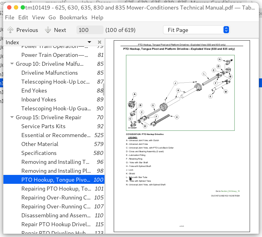
PTO Hookup, Tongue Pivot and Platform Driveline—Exploded View (830 and 835 only)................100
Repairing PTO Hookup, Tongue Pivot and Platform Driveline................101
Repairing Over-Running Coupler (830 and 835 Swivel Hitch Tongue Only)................105
Repairing Over-Running Coupler (830 and 835 Equal Angle Hitch Tongue Only)................107
Disassembling and Assembling Slip Clutch (830) (540 rpm only)................110
Repair PTO Hookup Driveline—600 Repair PTO Hookup Driveline—600 & 800 Series Equal Angle Tongues{pgNO}70 800 Series Equal Angle Tongues................115
Repair PTO Driveline Hub—Slip Clutch Type—600 Series................123
Repair PTO Driveline Slip Clutch—600 Series (If Equipped)................127
Adjust PTO Driveline Slip Clutch—600 Series (If Equipped)................129
Slipping Seized PTO Driveline Slip Clutch—600 Series (If Equipped)................131
Constant Velocity Joint Driveline Exploded View—600 Series................132
Repair PTO Constant Velocity Joint—600 Series................134
Adjust Gear Case Shield................144
Repairing Cutterbar Driveline................146
Repairing Upper Roll Driveline (Roll Conditioner)................149
Repairing Lower Roll Driveline (Roll Conditioner)................151
Group 20: Tongue Drive Shaft................71
Other Material................579
Specifications................580
Removing Long Tongue Drive Shaft (800 Series)................156
Installing Long Tongue Drive Shaft (800 Series)................158
Removing Short Tongue Drive Shaft................160
Installing Short Tongue Drive Shaft................162
Group 25: Drive Belts................71
Other Material................579
Specifications................580
Removing Main Drive Belt (800 Series)................166
Installing Main Drive Belt................168
Adjusting Main Drive Belt Tension................170
Removing and Installing Fixed Idler................171
Repairing Adjustable Idler Assembly................174
Replacing Drive and Driven Sheave Bearing (800 Series)................177
Replacing Return Sheave Bearing................180
Replacing Conditioner Drive Belt—Impeller Conditioner................182
Adjusting Conditioner Drive Belt Tension—Impeller Conditioner................186
Replacing Conditioner Drive Belt—Roll Conditioner................187
Adjusting Conditioner Drive Belt Tension—Roll Conditioner................190
Repairing Conditioner Adjustable Idler Assembly................191
Group 30: Hitch, Tongue and Platform Gear Cases................71
Essential or Recommended Tools................525
Other Material................579
Specifications................580
Removing and Installing Hitch and Tongue Gear Case Assembly—Two-Point Hitch................197
Disassembling Hitch and Tongue Drive Gear Cases................200
Inspecting Hitch and Tongue Drive Gear Cases................211
Assembling Hitch and Tongue Drive Gear Cases................213
Removing and Installing Cutterbar/Conditioner Gear Case................227
Group 35: Main Drive Gear Case Repair—800 Series................72
Essential or Recommended Tools................525
Service Equipment and Tools................380
Other Material................579
Specifications................580
Exploded View Of Cutterbar/Conditioner Gear Case (800 Series)................235
Disassembling and Assembling Cutterbar/Conditioner Gear Case (800 Series)................237
Group 40: Main Drive Gear Case Repair—600 Series................72
Other Material................579
Specifications................580
Replace Main Drive Gear Case Shaft Seals................265
Group 45: Roll Drive Gear Case (Roll Conditioner)................72
Essential or Recommended Tools................525
Other Material................579
Specifications................580
Disassembling and Assembling Roll Drive Gear Case................271
Section 70: Hydraulics................277
Group 05: General Information................277
Hydraulic Lift Cylinders Operation................280
Swing Cylinder Operation (800 Series)................282
Swing Cylinder Operation (600 Series)................284
Group 10: Diagnosing Malfunctions................342
Diagnose Lift Circuit Malfunctions................287
Diagnose Swing Circuit Malfunctions................288
Group 15: Lift Cylinders................277
Other Material................579
Specifications................580
Removing and Installing Lift Cylinder................292
Disassembling and Assembling Right Lift Cylinder................295
Disassembling and Assembling Left Lift Cylinder................300
Phasing Lift Cylinders................307
Group 20: Swing Cylinder................277
Other Material................579
Specifications................580
Removing and Installing Swing Cylinder (800 Series)................311
Remove and Install Swing Cylinder (600 Series)................312
Disassembling and Assembling Swing Cylinder (800 Series)................315
Disassembling and Assembling Swing Cylinder (600 Series)................324
Section 80: Miscellaneous................327
Group 05: Wheels and Wheel Support Assembly................327
Specifications................580
Remove and Install Wheel................330
Packing or Replacing Wheel Bearings................332
Repairing Wheel Support................334
Section 81: Carrier Frame and Tongue................337
Group 05: General Information................337
Tongue Description................339
Carrier Frame Description................340
Group 10: Diagnosing Malfunctions................342
Diagnosing Malfunctions................342
Group 15: Carrier Frame................337
Adjusting Carrier Frame Height................346
Group 20: Lift Arm................337
Specifications................580
Removing Left Lift Arm................351
Inspecting Left Lift Arm................353
Installing Left Lift Arm................354
Removing Right Lift Arm................356
Installing Right Lift Arm................358
Group 25: Limiting Chain................337
Positioning Limiting Chain................360
Group 30: Tongue................337
Essential or Recommended Tools................525
Specifications................580
Remove and Install Tongue (800 Series)................364
Remove and Install Tongue (600 Series)................368
Section 100: Cutting Components................374
Group 05: General Information................374
Cutterbar Description................377
Group 10: Cutterbar Repair................374
Essential or Recommended Tools................525
Service Equipment and Tools................380
Other Material................579
Specifications................580
Draining and Filling Cutterbar................384
Removing and Installing Cutterbar................386
Removing and Installing Single Intermediate Module from Cutterbar................395
Removing and Installing Converging Drums and Shields................404
Checking Dented Module................412
Repairing a Dented Module................413
Disassembling and Assembling Cutterbar................415
Removing and Installing Idler Gear Bearing From Idler Gear................421
Removing and Installing Left-Hand End Quill Assembly................428
Removing and Installing Right-Hand End or Intermediate Quill Assemblies................432
Cutterbar Quill and Pinion Gear Timing Detail—Disks Rotate Towards Cutterbar Center of Cutterbar................437
Checking Quill Bearing End Play................440
Inspecting Idler Gear Bearing................442
Disassembling and Assembling Quill Assembly................443
Replacing Left-Hand End Disk Driver................450
Replacing Intermediate Disk Drivers................456
Replacing Right-Hand End Disk Driver................461
Group 15: Disks and Knives................374
Specifications................580
Removing Disks................468
Installing and Synchronizing Disks................470
Checking Knife Wear................472
Checking Disk Wear................477
Removing and Installing Knives................479
Replacing Wear Cap On Knife Bolt................483
Group 25: Cutterbar Assembly................375
Removing and Installing Cross Tube................487
Section 110: Conditioner................489
Group 05: General Information................489
Conditioner Description................493
Group 10: Diagnosing Malfunctions................342
Diagnose Roll Conditioner Malfunctions................497
Diagnose Impeller Conditioner Malfunctions................499
Group 15: Roll Arms and Bearings................489
Essential and Recommended Tools................501
Other Material................579
Specifications................580
Removing Upper Roll Arm and Bearing—Left-Hand Side................504
Installing Upper Roll Arm and Bearing—Left-Hand Side................508
Removing Upper Roll Arm and Bearing—Right-Hand Side................512
Installing Upper Roll Arm and Bearing—Right-Hand Side................516
Replacing Lower Roll Bearing—Left-Hand Side................520
Replacing Lower Roll Bearing—Right-Hand Side................522
Group 20: Rolls................489
Essential or Recommended Tools................525
Other Material................579
Specifications................580
Removing and Installing Lower Roll................528
Removing and Installing Upper Roll................532
Install V-10 Rolls................536
Adjusting Roll Alignment................542
Adjusting Roll Timing................545
Adjusting Roll Pressure (Machines Ending With Serial No. —361671)................549
Adjusting Roll Pressure (Serial No. 370001—)................551
Adjusting Roll Spacing................553
Group 25: Impeller................489
Other Material................579
Specifications................580
Removing Impeller................558
Installing Impeller................559
Removing Impeller Bearing—Left-Hand Side................561
Installing Impeller Bearing—Left-Hand Side................563
Removing Impeller Bearing—Right-Hand Side................566
Installing Impeller Bearing—Right-Hand Side................569
Changing Impeller Rotor Speed................572
Section 120: Platform................575
Group 05: General Information................575
Platform Description................577
Group 10: Platform Repair................575
Other Material................579
Specifications................580
Adjusting Platform Float................581
Adjusting Cutting Height................582
Removing and Installing Gauge Shoes................585
Removing and Installing Platform................587
Section 240: Electrical System................591
Group 05: General Information................591
Electrical Circuit Malfunctions................593
Open Circuit................594
Grounded Circuit................595
Shorted Circuit................596
Symbols in System Diagrams................598
Component Identification Table................602
Group 10: Road Light................591
Tail/Warning Light Wiring Harness Diagram—Power Supply................605
Tail/Warning Light Main Wiring Harness Diagram—600 Series................606
Tail/Warning Light Main Wiring Harness Diagram—800 Series................609
Section 399: Special Tools — Dealer-Fabricated................612
Group 05: Manufacturing the Tools................612
Gear Case Lifting Eye................614
Tongue Lifting Bracket (800 Series)................615
John Deere Mower Conditioners Models 625, 630, 635, 830, 835 Repair Service Technical Manual (TM101419)
![]()