
John Deere Hay and Forage Round Balers 448 Standard & 458 Standard Repair Service Manual (TM1734)
Complete Repair Service Technical Manual for John Deere Hay and Forage Standard Round Balers Models 448 and 458, with all the shop information to maintain, diagnose, repair, and rebuild like professional mechanics.
John Deere 448 and 458 Standard Hay and Forage Round Balers workshop service & repair manual includes:
* Numbered table of contents easy to use so that you can find the information you need fast.
* Detailed sub-steps expand on repair procedure information
* Numbered instructions guide you through every repair procedure step by step.
* Troubleshooting and electrical service procedures are combined with detailed wiring diagrams for ease of use.
* Notes, cautions and warnings throughout each chapter pinpoint critical information.
* Bold figure number help you quickly match illustrations with instructions.
* Detailed illustrations, drawings and photos guide you through every procedure.
* Enlarged inset helps you identify and examine parts in detail.
TM1734 - John Deere Hay and Forage Round Balers 448 Standard & 458 Standard Technical Manual (Repair).PDF
TM1734 - John Deere Hay and Forage Round Balers 448 Standard & 458 Standard Technical Manual (Repair).EPUB
Total Pages: 1,071 pages
File Format: PDF (bookmarked, ToC, Searchable, Printable, high quality)
Language: English
MAIN SECTIONS
Foreword
General
Safety
Specifications
General Information
Lubricants
Drive Train
General Information
Diagnosing Malfunctions
Drive Train Protection
PTO Driveline
Remove and Install Gear Case
Gear Case Repair - Iberica
Gear Case Repair - Comer
Roll Drives
Rolls
Miscellaneous
Hydraulics
General Information
Diagnosing Malfunctions
Operation and Tests
Tensioning Valve Repair
Cylinder Repair
Twine Mechanism-Hydraulic
General Information
Diagnosing Malfunctions
Twine Wrap System Adjustments
Twine Wrap System Repair
Twine Mechanism-Electric
General Information
Diagnosing Malfunctions
Twine Wrap System Adjustments
Twine Wrap System Repair
Electrical System
General Information
Common Electrical Tests and Checks
Diagnosing Malfunctions
Tests and Adjustments
Tests and Adjustments-BALETRAK Pro System
Electrical Diagrams
Electrical Diagrams-BALETRAK™ PRO System
BALETRAK Pro Monitor-Controller Operations
Repair-BALETRAK Pro System
Connector Repair
Pickup
General Information
Diagnosing Malfunctions
Regular Pickup Repair
MEGAWIDE PLUS Pickup Repair (448 Only)
Miscellaneous
Miscellaneous
Wheel Repair
Gate Repair
Tension Arm Repair
Tongue Repair
Belt Repair
Main Frame Repair
TABLE OF CONTENTS...1
Section 10: General...16
Group 05: Safety...16
Recognize Safety Information...19
Understand Signal Words...20
Follow Safety Instructions...21
Operate Baler Safely...22
Protect Bystanders...23
Handle Fluids Safely—Avoid Fires...24
Prepare for Emergencies...25
Fire Prevention...26
Fire Prevention—Welding...27
Avoid High-Pressure Fluids...28
Support Machine Properly...29
Wear Protective Clothing...30
Work in Clean Area...31
Service Machine Safely...32
Illuminate Work Area Safely...35
Replace Safety Signs...36
Use Proper Lifting Equipment...37
Remove Paint Before Welding or Heating...38
Avoid Heating Near Pressurized Fluid Lines...39
Service Tires Safely...40
Practice Safe Maintenance...41
Use Proper Tools...43
Construct Dealer-Made Tools Safely...44
Decommissioning — Proper Recycling and Disposal of Fluids and Components...45
Live With Safety...46
Group 10: Specifications...1045
Machine Specifications...1045
Metric Bolt and Screw Torque Values...53
Unified Inch Bolt and Screw Torque Values...55
Face Seal Fittings Assembly and Installation—All Pressure Applications...57
Metric Face Seal Fitting Torque Chart—Standard Pressure Applications...58
Metric Face Seal Fitting Torque Chart—High Pressure Applications...60
SAE Face Seal Fitting Torque Chart—Standard Pressure Applications...62
SAE Face Seal Fitting Torque Chart—High Pressure Applications...64
Service Recommendations For 37° Flare and 30° Cone Seat Connectors...66
Group 15: General Information...17
Machine Description...70
Group 20: Lubricants...17
Multipurpose Extreme Pressure (EP) Grease...73
Gear Case Oil...74
Alternative and Synthetic Lubricants...75
Mixing of Lubricants...76
Lubricant Storage...77
Perform Lubrication and Maintenance...78
Section 20: Drive Train...79
Group 05: General Information...79
Drive Train Operation...85
Operating RPM...87
Group 10: Diagnosing Malfunctions...632
PTO Driveline Difficulties...89
Slip Clutch Alert Feature (If Equipped)...90
Slip Clutch Difficulties (If Equipped)...91
Shear Bolt Difficulties...92
Gear Case Difficulties...93
Drive Chain Difficulties...94
Group 15: Drive Train Protection...79
Service Parts Kits...418
Specifications...1045
Replace Driveline Shear Bolt...98
Repair PTO Driveline Hub—Shear Bolt Type...99
Check Slip Clutch Torque (MEGAWIDE PLUS)...102
Replace Pickup Slip Clutch...106
Repair PTO Driveline Hub—Slip Clutch Type (448 If Equipped)...110
Repair PTO Driveline Slip Clutch (448 If Equipped)...113
Adjust PTO Driveline Slip Clutch (448 If Equipped)...115
Slipping Seized PTO Driveline Slip Clutch (448 If Equipped)...117
Group 20: PTO Driveline...79
Other Material...895
Service Parts Kits...418
PTO Driveline Exploded View (W/Plastic Shields)—Shear Bolt Type...123
PTO Driveline Exploded View—Shear Bolt Type...125
PTO Driveline Exploded View—Slip Clutch Type...127
Repair Shields (Shear Bolt Type)...129
Install Shield...131
Repair U-joint (Shear Bolt Type)...133
Assemble U-joint...138
Repair PTO Lock-Back Collar Disconnect...141
Repair PTO Lock-Back Collar Disconnect (Shear Bolt Type)...143
Repair PTO Constant Velocity Joint...146
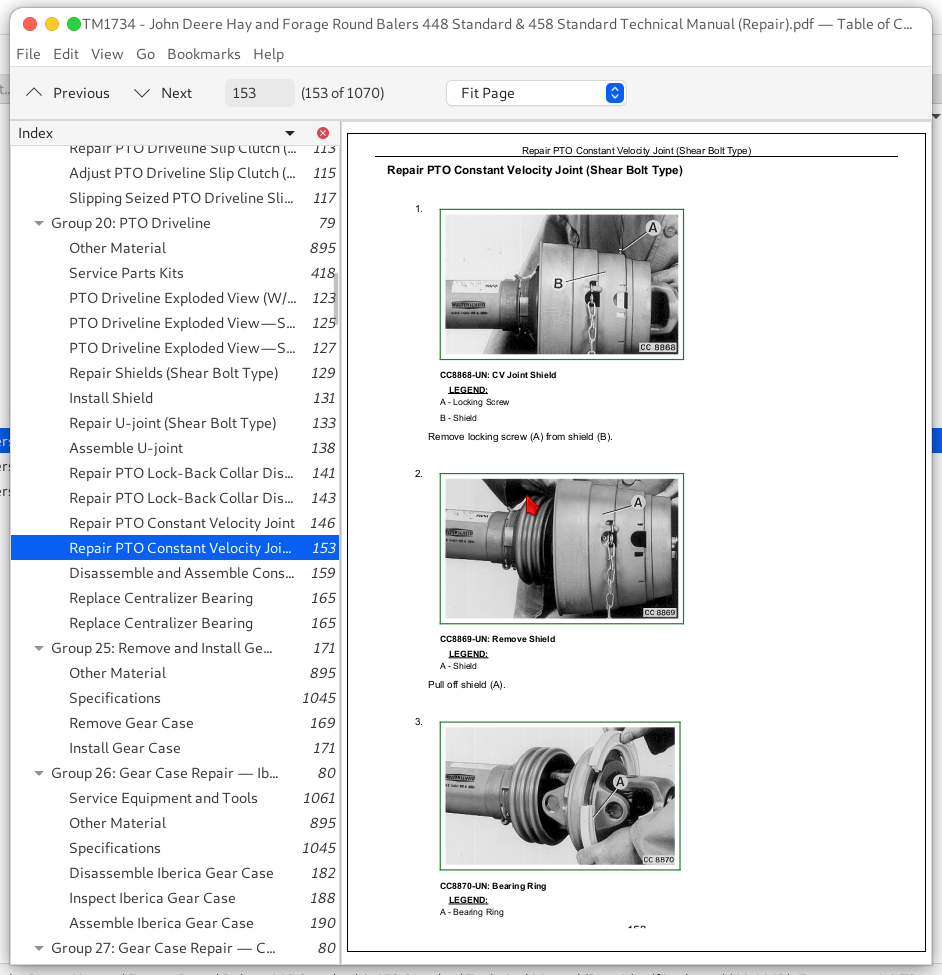
Repair PTO Constant Velocity Joint (Shear Bolt Type)...153
Disassemble and Assemble Constant Velocity Joint (Shear Bolt Type)...159
Replace Centralizer Bearing...165
Replace Centralizer Bearing...165
Group 25: Remove and Install Gear Case...171
Other Material...895
Specifications...1045
Remove Gear Case...169
Install Gear Case...171
Group 26: Gear Case Repair — Iberica...80
Service Equipment and Tools...1061
Other Material...895
Specifications...1045
Disassemble Iberica Gear Case...182
Inspect Iberica Gear Case...188
Assemble Iberica Gear Case...190
Group 27: Gear Case Repair — Comer...80
Essential or Recommended Tools...1043
Service Equipment and Tools...1061
Other Material...895
Specifications...1045
Disassemble Comer Gear Case...203
Inspect Comer Gear Case...214
Assemble Comer Gear Case...216
Group 30: Roll Drives...80
Specifications...1045
Adjust Lower Drive Roll Chain...235
Adjust Upper Drive Roll Chain (S.N.—370001)...236
Adjust Upper Drive Roll Chain (S.N. 370001—)...237
Check Starter Roll Drive Chain...238
Adjust Starter Roll Drive Chain...239
Replace Starter Roll Drive Chain...246
Check Upper Drive Roll Sprocket Alignment...248
Group 35: Rolls...81
Essential or Recommended Tools...1043
Service Equipment and Tools...1061
Other Material...895
Specifications...1045
Diagram of Rolls and Belt Routing-448...257
Diagram of Rolls and Belt Routing-458 Standard...259
Remove and Install Starter Roll...261
Remove and Install Belt Staggering Roll...271
Remove and Install Take-Up Arm Roll...275
Remove and Install Top Idler Roll...277
Remove and Install Auxiliary Take-Up Roll (If Installed)...279
Remove and Install Upper Rear Gate Roll...280
Remove and Install Lower Rear Gate Roll...282
Remove and Install Lower Front Gate Roll...284
Remove and Install Rear Roll of Tension Arm...286
Remove and Install Center and Front Rolls of Tension Arm...288
Replace Tension Arm Roll Shaft...290
Replace Stationary Shaft Roll Bearings...293
Remove and Install Lower Drive Roll...296
Install Lower Drive Roll Bearings With Internal Threads Recessed 44 mm (1-3/4 in.) From Shaft End...307
Install Lower Drive Roll Bearings With Internal Threads—Starting at End of Shaft...322
Remove and Install Upper Drive Roll...338
Install Upper Drive Roll Bearings...347
Group 40: Miscellaneous...81
Service Equipment and Tools...1061
Specifications...1045
Adjust Lower Front Gate Roll Scraper...363
Adjust Starter Roll Scraper (If Equipped)...365
Adjust Idler Roll Scraper (If Equipped)...367
Check for Twisted Gate...369
Check And Adjust Belt Tracking...370
Section 30: Hydraulics...371
Group 05: General Information...371
Hydraulic System Description and Diagram...374
Tensioning Valve...376
Low Pressure Relief Valve (Non-Adjustable)...377
High Pressure Relief Valve (Non-Adjustable)...378
Pilot-Operated Check Valve...379
Install Inline Orifice Correctly (458 STD Only)...380
Group 10: Diagnosing Malfunctions...632
Diagnosing Hydraulic Malfunctions...383
Group 15: Operation and Tests...371
Essential or Recommended Tools...1043
Specifications...1045
Hydraulic System Operation...388
Low Pressure Relief Valve Test...392
High-Pressure Relief Valve Test—Field Test...394
High-Pressure Relief Valve Test—Shop Test...396
Test Tension/Gate Cylinder for Leakage...400
Test Hydraulic Twine Arm and Pickup Lift Cylinders for Leakage...402
Group 20: Tensioning Valve Repair...371
Remove and Install Tensioning Valve...407
Disassemble and Inspect Tensioning Valve...410
Assemble Tensioning Valve...412
Check Condition of Valve Seat and Poppet...414
Group 25: Cylinder Repair...371
Essential or Recommended Tools...1043
Service Parts Kits...418
Remove and Install Gate Cylinder...419
Disassemble and Assemble Tension Arm Cylinder...422
Disassemble and Assemble Gate Cylinder...433
Disassemble and Assemble Twine Arm Cylinder...447
Section 40: Twine Mechanism—Hydraulic...454
Group 05: General Information...454
Twine Wrap System Description...528
Operating Twine Wrap Control...459
Adjust Twine Spacing (Double Twine Wrap)...461
Group 10: Diagnosing Malfunctions...632
Diagnosing Twine Wrap Malfunctions...474
Group 15: Twine Wrap System Adjustments...454
Specifications...1045
Adjust Twine Arm-to-Starter Roll, Cutter Link Support, and Twine Arm Stop...561
Adjust Twine Arm Distance From Right Sidesheet...568
Adjust Twine Cutter-to-Twine Arm Clearance...494
Adjust Twine Cutter Knife...572
Adjust Twine Cutter Contact Tab...575
Adjust Clearance Between Cutter Link Support and Twine Arm...578
Adjust Twine Cutter Tension...580
Adjust Front Twine Arm (Double Twine Arms)...508
Adjust Twine Indicator Retaining Strap...588
Adjust Twine End Spacing with Mechanical Twine Guides (448 Only)...512
Group 20: Twine Wrap System Repair...454
Other Material...895
Specifications...1045
Remove Hydraulic Twine Arm Cylinder...516
Install Hydraulic Twine Arm Cylinder...518
Attach Hydraulic Cylinder End Block to Twine Arm...521
Adjust Initial Length of Hydraulic Twine Arm Cylinder...523
Install Twine Arm Stop...599
Section 41: Twine Mechanism—Electric...526
Group 05: General Information...526
Twine Wrap System Description...528
Operate Twine Wrap Controller...529
Group 10: Diagnosing Malfunctions...632
Twine Wrap Difficulties...648
BALETRAK Pro Monitor-Controller Difficulties...639
Group 15: Twine Wrap System Adjustments...526
Specifications...1045
Adjust Twine Arm-to-Starter Roll, Cutter Link Support, and Twine Arm Stop...561
Adjust Twine Arm Distance From Right Sidesheet...568
Adjust Twine Cutter-to-Twine Arm...570
Adjust Twine Cutter Knife...572
Adjust Twine Cutter Contact Tab...575
Adjust Clearance Between Cutter Link Support and Twine Arm...578
Adjust Twine Cutter Tension...580
Adjust Front Twine Arm...585
Adjust Twine Indicator Retaining Strap...588
Adjust Twine Guide(s) (If Equipped)...589
Adjust Twine Spacing (Double-Twine Wrap)...590
Group 20: Twine Wrap System Repair...526
Specifications...1045
Remove and Install Twine Arm Actuator...594
Install Twine Arm Actuator, Adapter, and Pivot Assembly...596
Install Twine Arm Stop...599
Section 60: Electrical System...600
Group 05: General Information...600
Electrical System Description 448 and 458 Standard Hydraulic Twine...606
Electrical System description- BaleTrak Pro (Optional) (458 Standard SN352001—)...608
Group 10: Common Electrical Tests and Checks...600
Service Equipment and Tools...1061
Checks Before Testing...615
Electromagnetic Interference (EMI)...616
Basic Informational Warnings for Machines Equipped With Computer Controlled Systems...617
Electrical Circuit Definition...618
Electronic Circuit Definition...619
Common Circuit Test...621
Electrical Circuit Malfunctions...622
Probe Light Check—Voltage from Battery...626
Probe Light Check—Continuity to Ground...627
Seven-Step Electrical Test Procedure...628
Group 15: Diagnosing Malfunctions...632
Diagnosing Malfunctions...632
Activating BaleTrak™ Pro Monitor-Controller Alarms...634
BALETRAK Pro Monitor Error Codes...635
BALETRAK Pro Monitor-Controller Difficulties...639
Twine Wrap Difficulties...648
Group 16: Tests and Adjustments...600
Specifications...1045
Test Bale Size (Buzzer) Circuit...661
Adjust Bale Size Switch (448 baler and 458 Standard with Hydraulic Twine)...662
Adjust Bale Size Link For Maximum Bale Size (Oversize Warning 448 And 458 Standard With Hydraulic Twine)...664
Test Microswitch...666
Test Buzzer...667
Group 20: Tests and Adjustments—BALETRAK Pro System...600
Specifications...1045
Access BaleTrak™ Pro Monitor Diagnostic and Setup Modes...670
BALETRAK Pro Monitor-Controller Customer Channels...672
BALETRAK™ Pro Monitor-Controller Channels...673
Channel 001: Reset BaleTrak™ Pro Monitor-Controller To Initial Settings...674
Channel 002: Dry Straw Twine Wrap Program...675
Channel 003: Set Twine Re-Extension...676
Channel 004: Set Cinch Wrap...678
Channel 005: Adjust Bale Diameter Sensor...679
Replace and Adjust Bale Diameter Sensor Mounting Bracket...779
Adjust Bale Diameter Display...683
Channel 008: Change Display to Metric or English Units...685
Channel 010: Set Near-Full Indicator Set Point...686
Channels 013 and 014: Gate Close and Oversize Bale Switches...688
Adjust Oversize Bale Switch...690
Adjust Bale Size Link for Maximum Bale Size (Oversize Warning 448 And 458 BaleTrak™ Pro)...692
Testing Twine or Net Wrap Actuator Current (Channel 018)...694
Channel 019: Test Tractor Convenience Outlet Voltage...696
Channel 020: Test Liquid Crystal Display (LCD) Panel...697
Channel 029: Calibrate Twine Arm...698
Channel 030: Twine Actuator Stroke...700
Channel 033: Adjust Delay of Twine Eject Icon...701
Checking Microswitches...703
Test Sensors...704
BALETRAK Pro Monitor-Controller Setup Channels...705
Channel 201: Change Baler Model...706
Channel 202: Enable Twine Option...709
Channel 204: Setup PTO RPM Sensor...712
Channel 205: Setup Pickup RPM Sensor...714
Channel 206: Calibrate PTO RPM Sensor...715
Channel 207: Calibrate Pickup RPM Sensor...717
BALETRAK Pro Monitor-Controller Diagnostic Channels...719
Channels 301—306: Diagnostic Trouble Codes and Bale Count Memory...720
Channel 307: View Minutes Counter...724
Channel 308: View Hours Counter...725
Channel 309: Lowest Battery Voltage Level Recorded...726
Channel 310: Highest Battery Voltage Level Recorded...728
Channel 311: Controller Software Version...730
Channel 312: Total Bale Counter...731
Group 25: Electrical Diagrams...602
Wire Color Chart...733
Baler Wiring Harness Diagram...734
Wiring Diagram—Electric Twine Wrap (Optional)...737
Group 27: Electrical Diagrams—BALETRAK™ PRO System...602
BALETRAK™ PRO System Component Locations...739
Wiring Harness Diagram—BALETRAK™ PRO Monitor-Controller 458 Standard (350001—)...740
Wiring Harness Diagram—Baler...744
Wiring Diagram—BaleTrak™ Pro Monitor-Controller System...748
BaleTrack Pro Control System Wiring Diagram...749
Group 30: BALETRAK Pro Monitor-Controller Operations...602
BALETRAK Pro Monitor-Controller Keys and Switches...751
BaleTrak™ Pro Monitor-Controller Displays and Indicators...752
BaleTrak™ Pro Monitor-Controller Operation...753
BaleTrak™ Pro Monitor-Controller Specifications...1045
BaleTrak™ Pro Monitor-Controller Setup Values and Initial Settings...756
Viewing and Resetting Bale Counters...758
Adjusting Audible Alarm Volume...760
Setting Bale Diameter...761
Adjusting Bale Diameter Display...762
Twine Wrap Terms and Settings...764
Using Manual Actuator, Wrap, and Bypass Switches...766
Using Bypass Switch (Twine Wrap Only)...768
Group 35: Repair—BALETRAK Pro System...602
Specifications...1045
Programming BaleTrak™ Pro...771
Replace Monitor-Controller LCD Backlight Bulbs...772
Replace Monitor-Controller LCD Panel...773
Replace Monitor-Controller Audible Alarm...776
Replace Bale Diameter Sensor...777
Replace and Adjust Bale Diameter Sensor Mounting Bracket...779
Adjusting Gate Close Switch...781
Replace Gate Closed Switch...782
Replace Oversize Bale Switch...783
Replace BaleTrak™ Pro Computer Chip (EEPROM)...784
Group 40: Connector Repair...603
Essential or Recommended Tools...1043
Other Material...895
Electrical Connector Handling...791
Use Terminal Cleaner and Di-Electric Grease...792
Connector Identification...793
Replace WEATHER PACK Connector...795
Install WEATHER PACK Terminal...797
Remove Connector Body from Blade Terminals...799
Replace DEUTSCH Connectors...800
Install DEUTSCH Terminal Connectors...802
Replace CPC Blade Type Connectors...804
Replace Small MATE-N-LOC Pin Connector...805
Harness Repair—Splice Connector...806
Harness Repair (Splice, Broken or Cut Wire)...807
Section 70: Pickup...809
Group 05: General Information...809
Specifications...1045
Pickup Description...813
Preliminary Checks...814
Check Pickup Tooth End Play...816
Group 10: Diagnosing Malfunctions...632
Pickup Difficulties...823
Feeding Difficulties...827
Feeding Difficulties With Roller Baffle...831
Group 15: Regular Pickup Repair...809
Service Equipment and Tools...1061
Other Material...895
Specifications...1045
Replace Teeth (Pickup Installed)...923
Replace Cam Follower Bearings...927
Remove and Install Pickup...929
Disassemble Pickup...937
Inspect Pickup Components...946
Assemble Pickup...949
Pickup Drive Belt and Chain Alignment...884
Adjust Initial Length of Drive Belt Idler Spring...886
Adjust Drive Belt Idler...887
Adjust Pickup Float Springs...978
Adjusting Pickup Float Springs—458 Standard...891
Group 25: MEGAWIDE PLUS Pickup Repair (448 Only)...809
Service Equipment and Tools...1061
Other Material...895
Specifications...1045
Remove and Install Roller Baffle...898
Repair Roller Baffle...900
Balancing Roller Baffle...907
Remove and Install Compressor Rack Assembly (MEGAWIDE PLUS)...909
Remove and Install MEGAWIDE PLUS Pickup/Rotor Assembly...910
MEGAWIDE PLUS Pickup/Rotor Frame-to-Baler Frame Shimming Procedure...919
Replace Teeth (Pickup Installed)...923
Replace Cam Follower Bearings...927
Remove and Install Pickup...929
Disassemble Pickup...937
Inspect Pickup Components...946
Assemble Pickup...949
Remove and Install Auger/Rotor Assembly...964
Disassemble and Assemble Auger/Rotor and Shaft Assembly...969
Pickup Drive Chains Alignment...971
Adjust Auger Scrapers...974
Adjust Pickup Drive Chains...975
Adjust Pickup Float Springs...978
Adjust Compressor Rods (MEGAWIDE PLUS)...980
Group 30: Miscellaneous...810
Service Equipment and Tools...1061
Specifications...1045
Adjust Initial Length of Hydraulic Lift Cylinder (If Equipped)...985
Repair Gauge Wheel—Regular Pickup...986
Repair Gauge Wheel—MEGAWIDE PLUS Pickup...988
Remove and Install Gauge Wheel Arm Assembly MegaWide Plus Pickup...990
Section 80: Miscellaneous...992
Group 05: Wheel Repair...992
Service Equipment and Tools...1061
Specifications...1045
Remove and Install Baler Wheel...997
Inspect and Replace Baler Wheel Bearings...999
Repair Gathering Wheel (If Equipped)...1001
Remove Excessive Play from Gathering Wheel Pivot...1004
Group 10: Gate Repair...992
Specifications...1045
Straighten Gate...1008
Remove and Install Gate...1011
Attach Bale Shape Indicator Cables...1015
Adjust Gate Lock Rod...1019
Group 15: Tension Arm Repair...992
Specifications...1045
Remove and Install Tension Arm...1024
Adjust Take-Up Arm Spring (448)...1027
Adjust Take-Up Arm Spring (458 Standard)...1028
Adjust Bale Size Indicator...1030
Inspect Tension Arm Wear Channel...1031
Replace Tension Arm Wear Channel...1033
Group 20: Tongue Repair...992
Specifications...1045
Remove and Install Tongue...1038
Group 25: Belt Repair...992
Essential or Recommended Tools...1043
Service Equipment and Tools...1061
Specifications...1045
Remove Belts...1046
Install Belts...1047
Prepare Belts For New Lacings...1049
Install Belt Lacing...1053
Belts Eligible for Warranty Replacement...1056
Belts Not Eligible for Warranty Replacement...1057
Group 30: Main Frame Repair...993
Service Equipment and Tools...1061
Straighten Main Frame...1062
John Deere Hay and Forage Round Balers 448 Standard & 458 Standard Repair Service Manual (TM1734)
![]()