
John Deere Silage Special Models 469s, 569s; Round Balers Models 469, 569 All Inclusive Diagnostic and Repair Service Technical Manual (TM121219)
Complete Diagnostics and Repair Technical Service Manual with Electrical Wiring Diagrams for John Deere Silage Special Models 469s, 569s; Round Balers Models 469, 569, with all the shop information to maintain, diagnose, repair, and rebuild like professional mechanics.
John Deere Silage Special Models 469s, 569s; Round Balers Models 469, 569 workshop Diagnosis & Repair manual includes:
* Numbered table of contents easy to use so that you can find the information you need fast.
* Detailed sub-steps expand on repair procedure information
* Numbered instructions guide you through every repair procedure step by step.
* Troubleshooting and electrical service procedures are combined with detailed wiring diagrams for ease of use.
* Notes, cautions and warnings throughout each chapter pinpoint critical information.
* Bold figure number help you quickly match illustrations with instructions.
* Detailed illustrations, drawings and photos guide you through every procedure.
* Enlarged inset helps you identify and examine parts in detail.
TM121219 - John Deere Silage Special Models 469s, 569s; Round Balers Models 469, 569 All Inclusive Technical Manual (Diagnosis Operation Test Repair Service).PDF
TM121219 - John Deere Silage Special Models 469s, 569s; Round Balers Models 469, 569 All Inclusive Technical Manual (Diagnosis Operation Test Repair Service).EPUB
Total Pages: 1,214 pages
File Format: PDF/EPUB/MOBI/AZW (PC/Mac/Android/Kindle/iPhone/iPad; bookmarked, ToC, Searchable, Printable)
Language: English
MAIN SECTIONS
Foreword
General
Safety
Specifications
General Information
Lubricants
Drive Train
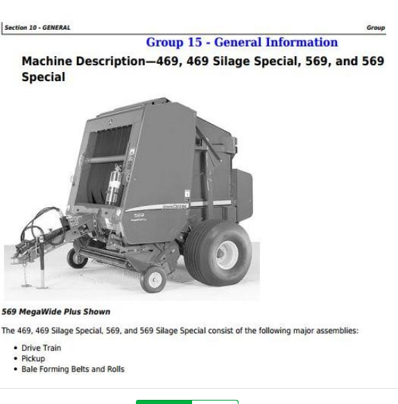
General Information
Diagnosing Malfunctions
Drive Train Protection
PTO Driveline
Remove and Install Gear Case
Gear Case Repair
Roll Drives
Rolls
Miscellaneous
Hydraulics
General Information
Diagnosing Malfunctions
Operation and Tests
Tensioning Valve Repair
Gate Lock Valve Repair
Cylinder Repair
Twine Mechanism-Electric
General Information
Diagnosing Malfunctions
Twine Wrap System Adjustments
Twine Wrap System Repair
COVEREDGE Net Wrap System (If Equipped)
General Information
Diagnosing Malfunctions
Net Wrap Repair
Electrical System
General Information
Common Electrical Tests and Checks
Diagnosing Malfunctions-BALETRAK Pro System
Tests and Adjustments-BALETRAK Pro System
Electrical Diagrams-BALETRAK Pro System
BALETRAK Pro Monitor-Controller Operations
Repair-BALETRAK Pro System
Connector Repair
Pickup
General Information
Diagnosing Malfunctions
Regular Pickup Repair (569 Only)
MEGATOOTH Pickup Repair (569 Only)
MEGAWIDE PLUS Pickup Repair
Miscellaneous
Miscellaneous
Wheel Repair
Gate Repair
Tension Arm Repair
Tongue Repair
Belt Repair
Main Frame Repair
Dealer Fabricated Tools
tm121219 - 469, 469 Silage Special, 569, and 569 Silage Special Round Balers
Table of Contents
Foreword
Section 10: General
Group 05: Safety
Recognize Safety Information
Understand Signal Words
Follow Safety Instructions
Handle Fluids Safely—Avoid Fires
Prevent Battery Explosions
Prepare for Emergencies
Park Machine Safely
Operate Baler Safely
Protect Bystanders
Service Machine Safely—469, 469S, 569, 569S
Support Machine Properly
Wear Protective Clothing
Work in Clean Area
Service Machines Safely
Work In Ventilated Area
Illuminate Work Area Safely
Replace Safety Signs
Use Proper Lifting Equipment
Avoid High-Pressure Fluids
Remove Paint Before Welding or Heating
Avoid Heating Near Pressurized Fluid Lines
Service Tires Safely
Practice Safe Maintenance
Use Proper Tools
Construct Dealer-Made Tools Safely
Dispose of Waste Properly
Precautions for Welding
Protect Against High Pressure Spray
Live With Safety
Group 10: Specifications
469, 469 Silage Special , 569, and 569 Silage Special Round Baler Specifications
Metric Bolt and Screw Torque Values
Unified Inch Bolt and Screw Torque Values
Metric Face Seal Fitting Torque Chart—Standard Pressure Applications
Metric Face Seal Fitting Torque Chart—High Pressure Applications
SAE Face Seal Fitting Torque Chart—Standard Pressure Applications
SAE Face Seal Fitting Torque Chart—High Pressure Applications
Service Recommendations For 37° Flare and 30° Cone Seat Connectors
Group 15: General Information
Machine Description—469, 469 Silage Special, 569, and 569 Silage Special
Group 20: Lubricants
Grease
Gear Case Oil
Alternative and Synthetic Lubricants
Mixing of Lubricants
Lubricant Storage
Perform Lubrication and Maintenance
Section 20: Drive Train
Group 05: General Information
Drive Train Operation
Group 10: Diagnosing Malfunctions
PTO Driveline Difficulties
Slip Clutch Alert Feature (If Equipped)
Gear Case Difficulties
Drive Chain Difficulties
Group 15: Drive Train Protection
Service Parts Kits
Specifications
Turn Slip Clutch Alert System On/Off
Replace PTO Slip Clutch Alert Sensor
Replace Pickup Slip Clutch Alert Sensor
Adjust PTO and Pickup Slip Clutch Alert Sensors (MegaWide™ Plus and MegaTooth™ Pickups)
Check Slip Clutch Torque (MegaWide™ PLUS)
Replace Pickup Slip Clutch
Repair PTO Driveline Hub—Slip Clutch Type
Repair PTO Driveline Slip Clutch (If Equipped)
Adjust PTO Driveline Slip Clutch
Starter Roll End Play Adjustment
Slipping Seized PTO Driveline Slip Clutch (If Equipped)
Group 20: PTO Driveline
Other Material
Service Parts Kits
PTO Driveline Exploded View—Slip Clutch Type
Repair PTO Lock-Back Collar Disconnect
Repair PTO Constant Velocity Joint
Group 25: Remove and Install Gear Case
Other Material
Specifications
Remove Gear Case
Install Gear Case
Convert Baler to 1000 RPM
Replace Hex Shaft from Gear Case-to-Sidesheet
Group 27: Gear Case Repair
Essential or Recommended Tools
Service Equipment and Tools
Other Material
Specifications
Disassemble Gear Case
Inspect Gear Case
Assemble Gear Case
Group 30: Roll Drives
Specifications
Adjusting Lower Drive Roll Chain
Adjusting Upper Drive Roll Chain
Check Starter Roll Drive Chain
Adjust Starter Roll Drive Chain
Replace Starter Roll Drive Chain
Remove and Install Starter Roll Sprocket
Remove and Install Lower Drive Roll Sprocket
Check Upper Drive Roll Sprocket Alignment
Group 35: Rolls
Service Equipment and Tools
Other Material
Specifications
Diagram of Rolls and Belt Routing—469 and 569
Diagram of Rolls and Belt Routing—469S and 569S
Remove and Install Starter Roll
Remove and Install Belt Staggering Roll
Remove and Install Cleaning Auger Roll 459S and 559S
Checking and Adjusting Clearance Between Cleaning Auger and Staggered Belt Roll
Remove and Install Front Idler Roll
Remove and Install Take-Up Arm Roll
Remove and Install Top Idler Roll
Remove and Install Auxiliary Take-Up Roll
Remove and Install Upper Rear Gate Roll
Remove and Install Lower Rear Gate Roll—without CoverEdge Net Wrap
Remove and Install Lower Rear Gate Roll—with CoverEdge Net Wrap
Remove and Install (No. 9) Lower Front Gate Roll (With or Without Net Wrap)
Remove and Install Rear Roll of Tension Arm
Remove and Install Center and Front Rolls of Tension Arm
Replace Tension Arm Roll Shaft
Replace Stationary Shaft Roll Bearings
Remove and Install Lower Drive Roll
Replacing Left-Hand Lower Drive Roll Bearing
Replacing Right-Hand Lower Drive Roll Bearing
Remove Upper Drive Roll
Install Upper Drive Roll
Install Upper Drive Roll Bearings
High-Moisture Kit (Silage Baling) Difficulties
Group 40: Miscellaneous
Service Equipment and Tools
Specifications
Adjust Lower Front Gate Roll Scraper
Adjust Starter Roll Scraper (If Equipped)
Adjust Idler Roll Scraper (If Equipped)
Check Belt Tracking
Adjust Belt Tracking without COVEREDGE Net Wrap
Adjust Belt Tracking with COVEREDGE Net Wrap
Section 30: Hydraulics
Group 05: General Information
Hydraulic System Description and Diagram
Tensioning Valve
High Pressure Adjustable Relief Valve
High Pressure Relief Valve (Non Adjustable)
Low Pressure Relief Valve (Non Adjustable)
Pilot-Operated Check Valves
Optional Variable (Soft) Core Solenoid Valve
Install Inline Orifice Correctly
Bale Density Gauge
Group 10: Diagnosing Malfunctions
Diagnosing Hydraulic Malfunctions
Group 15: Operation and Tests
Essential or Recommended Tools
Specifications
Hydraulic System Operation
Low Pressure Relief Valve Test
Check Adjustable Relief Valve
Test Tension or Gate Cylinder for Leakage
Test Pickup Lift Cylinder for Leakage
Test Gate Lock Valve for Leakage
Group 20: Tensioning Valve Repair
Remove and Install Tensioning Valve
Disassemble and Inspect Tensioning Valve
Assemble Tensioning Valve
Check Condition of Valve Seat and Poppet
Install Check Valves Correctly
Group 25: Gate Lock Valve Repair
Repair Gate Lock Valve
Group 30: Cylinder Repair
Service Parts Kits
Remove and Install Gate Cylinder
Disassemble and Assemble Tension Arm Cylinder
Disassemble and Assemble Gate Cylinder
Section 41: Twine Mechanism—Electric
Group 05: General Information
Twine Wrap System Description
Understanding Twine Wrap Terms and Settings
Group 10: Diagnosing Malfunctions
Twine Wrap Difficulties
BALETRAK Pro Monitor-Controller Difficulties
Group 15: Twine Wrap System Adjustments
Specifications
Adjust Twine Arm-to-Starter Roll, Cutter Link Support, and Twine Arm Stop
Adjust Twine Cutter-to-Twine Arm
Check and Adjust Twine Cutter Knife
Adjust Twine Cutter Contact Tab
Adjust Clearance Between Cutter Link Support and Twine Arm
Adjust Twine Cutter Tension
Adjust Front Twine Arm
Adjust Twine Indicator Retaining Strap
Set Twine End Wrap Distance
Set Twine Spacing
Group 20: Twine Wrap System Repair
Specifications
Remove and Install Twine Arm Actuator—469 and 469S
Install Twine Arm Actuator, Adapter, and Pivot Assembly—469 and 469S
Remove and Install Twine Arm Actuator—569 and 569S
Install Twine Arm Actuator, Adapter, and Pivot Assembly—569 and 569S
Install Twine Arm Stop—469 and 469S
Install Twine Arm Stop—569 and 569S
Install Twine Arm and Twine Arm Drive Gear—569 and 569S
Section 50: Net Wrap System (If Equipped)
Group 05: General Information
Other Material
Specifications
System Description
Switch Description
Setting Number of Net Wraps (If Equipped)
Monitor Display for B-Wrap Baling
Correct Feeding Problems
Using Net Wrap After Extended Storage
Check and Adjust Net Wrap Pan
Check and Straighten Net Pan Angle
Checking and Adjusting Net Pan Pressure without Leaf Spring
Group 10: Diagnosing Malfunctions
Net Wrap Difficulties
BALETRAK Pro Monitor-Controller Difficulties
Group 15: Net Wrap Repair
Specifications
Remove and Install Net Wrap Assembly
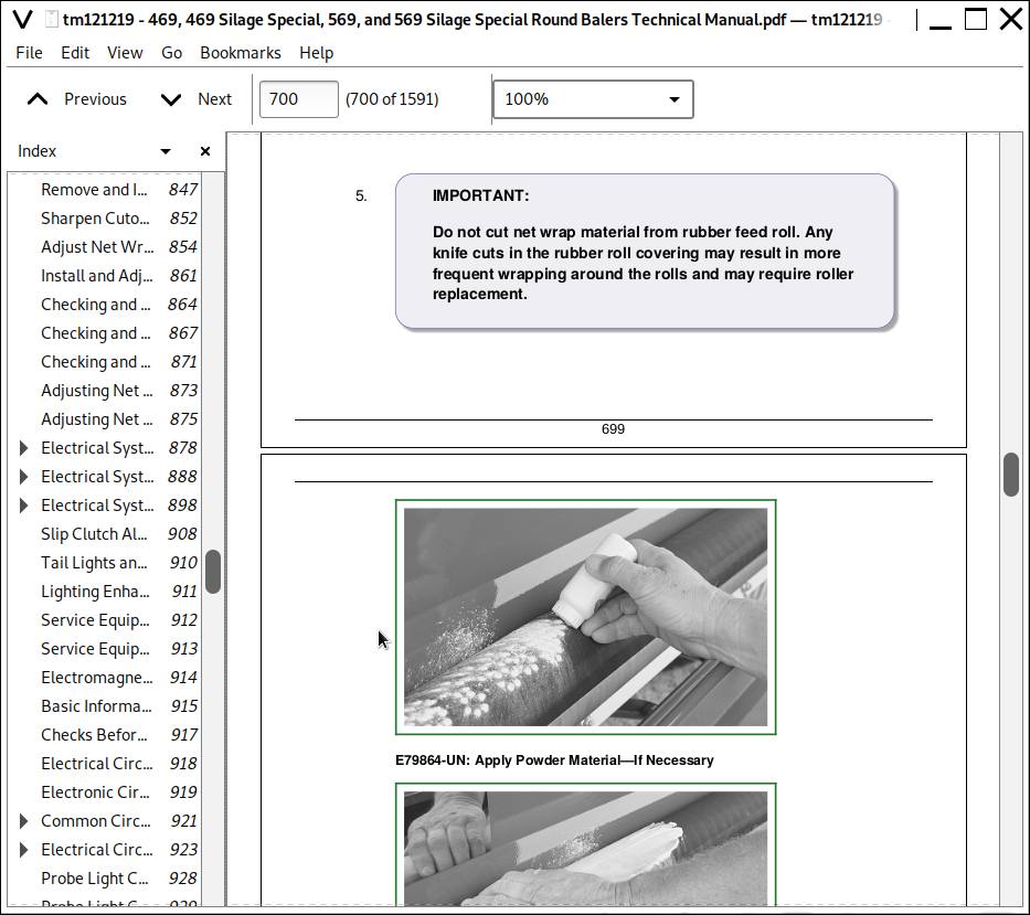
Repair Cuts on Feed Roll
Remove and Install Upper (Rubber) Feed Roll
Replace Upper Feed Roll Bearings
Remove and Install Lower (Steel) Feed Roll
Remove and Install Lower Net Wrap Guide
Adjust Lower Net Wrap Guide
Checking and Adjusting Net Pan Pressure
Replace Lower Front Gate Roll Belt Guide
Replace Cover Hinge Seal
Check Cover Gas Springs
Check and Adjust Cover Latch
Remove Net Wrap Actuator
Install Net Wrap Actuator
Removing and Installing Net Wrap V-Belt
Check and Adjust Net Wrap V-Belt Idler Tension
Check and Adjust Net Wrap Switch
Replace Net Wrap Switch or Switch Arm
Remove and Install Cutoff Knife
Sharpen Cutoff Knife
Adjust Net Wrap Counterknife
Install and Adjust Net Wrap Brush
Checking and Adjusting Brake Pad
Checking and Adjusting Net Wrap Feed Roll Brake
Checking and Adjusting Net Wrap Feed Roll Brake Spring
Adjusting Net Wrap Feed Roll Pressure
Adjusting Net Wrap Stretch
Section 60: Electrical System
Group 05: General Information
Electrical System Description—BALETRAK Pro
Slip Clutch Alert
Tail Lights and Warning Lights
Lighting Enhancement Module Operation
Group 10: Common Electrical Tests and Checks
Service Equipment and Tools
Electromagnetic Interference (EMI)
Basic Informational Warnings for Machines Equipped With Computer Controlled Systems
Checks Before Testing
Electrical Circuit Definition
Electronic Circuit Definition
Common Circuit Test
Electrical Circuit Malfunctions
Probe Light Check—Voltage from Battery
Probe Light Check—Continuity to Ground
Seven-Step Electrical Test Procedure
Group 15: Diagnosing Malfunctions—BALETRAK Pro System
Activating BaleTrak Pro Monitor-Controller Alarms
BALETRAK Error Codes
BALETRAK Pro Monitor-Controller Difficulties
Group 20: Tests and Adjustments—BALETRAK Pro System
Specifications
Access BaleTrak Pro Customer, Setup, and Diagnostic Channels
BaleTrak Pro Monitor-Controller Channels
Channel 001: Reset BaleTrak Pro Monitor-Controller to Initial Settings
Channel 002: Dry Straw Twine Wrap Program
Channel 003: Set Twine Re-Extension
Channel 004: Set Cinch Wrap
Adjusting Bale Diameter Sensor (Channel 005)
Adjust Bale Diameter Display
Channel 006: Adjust Net Wrap Delay
Channels 007 and 009: Adjust Bale Shape Sensor
Channels 007 and 009: Adjust Bale Shape Bar Display—Field Procedure
Channel 008: Change Display to Metric or English Units
Channel 010: Set Near-Full Indicator Set Point
Channel 011: Set Bale Shape Sensitivity
Channel 012: Test Net Wrap Switch
Channel 013: B-Wrap Sensor (when enabled)
Adjust B-Wrap Sensor
Channels 013, 014 and 015 Gate Latch and Oversize Bale Switches—Monitor-Controller Assisted Test
Remove and Install Gate Latch Proximity Switches
Adjust Gate Latch Proximity Switches
Adjusting Oversize Bale Switch
Channels 016 and 017: Checking PTO and Pickup Speed
Channel 018: Test Twine or Net Wrap Actuator Current
Channel 019: Test Tractor Convenience Outlet Voltage
Channel 020: Test Liquid Crystal Display (LCD) Panel
Channel 029: Calibrate Twine Arm
Channel 033: Adjust Delay of Twine Eject
Channel 034: Adjust Cut Position
Channel 035: Adjust Bale Orientation
Checking Microswitches
Test Sensors
BALETRAK Pro Monitor-Controller Setup Channels
Channel 201: Change Baler Model
Channel 202: Enable Twine Feature
Channel 203: Enable Net Wrap and B-Wrap Feature
Channel 204: Slip Clutch Alert PTO Speed Sensor
Channel 205: Slip Clutch Alert Pickup RPM Sensor
Channels 206 and 207: Calibrate Slip Clutch Alert PTO and Pickup RPM Sensors
Channel 208: Activating Optional Variable Core Operation
BALETRAK Pro Monitor-Controller Diagnostic Channels
Channels 301—306: Diagnostic Trouble Codes and Bale Count Memory
Channel 307: View Minutes Counter
Channel 308: View Hours Counter
Channel 309: Lowest Battery Voltage Level Recorded
Channel 310: Highest Battery Voltage Level Recorded
Channel 311: Controller Software Version
Channel 312: Total Bale Counter
Group 25: Electrical Diagrams—BALETRAK Pro System
BaleTrak Pro Component Locations
Electrical Schematic
Baler Lighting Electrical Schematic
Wiring Harness Diagram—BaleTrak Pro Monitor-Controller
Wiring Harness Connector Diagram
Wiring Harness Diagram—B-Wrap Sensor Extension
Group 30: BaleTrak Pro Monitor-Controller Operations
BaleTrak Pro Monitor-Controller Keys and Switches
BaleTrak Pro Monitor-Controller Displays and Indicators
BaleTrak Pro Monitor-Controller Operation
BaleTrak Pro Monitor-Controller Specifications
BaleTrak Pro Monitor-Controller Setup Values and Initial Settings
Viewing and Resetting Bale Counters
Adjusting Audible Alarm Volume
Using Manual Actuator, Wrap, and Bypass Switches
Using Bypass Switch (Twine Wrap Only)
Group 35: Repair—BALETRAK Pro System
Specifications
Programming BaleTrak Pro
Resetting BaleTrak Pro Monitor-Controller To Initial Settings (Channel 001)
Replace BaleTrak Pro Computer Chip (EEPROM)
Replace Monitor-Controller LCD Backlight Bulbs
Replace Monitor-Controller LCD Panel
Replace BaleTrak Pro Monitor-Controller Faceplate
Replace Monitor-Controller Audible Alarm
Replace Bale Diameter Sensor
Replace Bale Shape Sensor
Replace Oversize Bale Switch
Replace Variable (Soft) Core Solenoid Coil (If Equipped)
Group 40: Connector Repair
Essential or Recommended Tools
Other Material
Using High-Pressure Washers
Electrical System Visual Inspection
Electrical Connector Handling
Installation of Repair Wire Assembly (RWA)
Use Electrical Insulating Compound
Use Terminal Cleaner and Di-Electric Grease
Harness Repair—Splice Connector
Repair Procedure R-A
Repair Procedure R-B
Repair Procedure R-E
Repair Procedure R-J
Section 70: Pickup
Group 05: General Information
Pickup Description
Preliminary Checks
Check Pickup Tooth End Play
Group 10: Diagnosing Malfunctions
Pickup Difficulties
Feeding Difficulties
General Baler Difficulties
Group 15: Regular Pickup Repair (569 Only)
Other Material
Specifications
Replace Cam Follower Bearings
Remove and Install Pickup
Disassemble Pickup
Inspect Pickup Components
Assemble Pickup
Pickup Drive Belt and Chain Alignment
Adjust Initial Length of Drive Belt Idler Spring
Adjust Drive Belt Idler
Adjust Pickup Float Springs Regular Pickup
Remove and Install Compressor Rack Assembly (Regular Pickup) 569 Only
Adjusting Compressor Rack Assembly (Regular Pickup) 569 Only
Group 20: MEGATOOTH Pickup Repair (569 Only)
Other Material
Specifications
Replace Teeth (Pickup Installed)
Replace Cam Follower Bearings—Left-Hand Side
Replace Cam Follower Bearings—Right-Hand Side
Remove and Install Pickup (MEGATOOTH)
Disassemble Pickup
Inspect Pickup Components
Assemble Pickup
Adjust Float Springs
Group 25: MEGAWIDE PLUS Pickup Repair
Service Equipment and Tools
Other Material
Specifications
Remove and Install Roller Baffle
Repair Roller Baffle
Balancing Roller Baffle
Remove and Install Compressor Rack Assembly (MEGAWIDE PLUS)
Adjust Compressor Rods (MEGAWIDE PLUS)
Remove and Install MEGAWIDE PLUS Pickup/Rotor Assembly
MEGAWIDE PLUS Pickup/Rotor Frame-to-Baler Frame Shimming Procedure
Replace Cam Follower Bearings
Remove and Install Pickup Cam
Remove and Install Pickup (MEGAWIDE PLUS)
Disassemble Pickup
Inspect Pickup Components
Assemble Pickup
Remove and Install Auger/Rotor Assembly
Disassemble and Assemble Auger/Rotor Assembly
Pickup Drive Chains Alignment
Adjust Auger Scrapers
Adjust Pickup Drive Chains
Adjust Pickup Float Springs (MEGAWIDE PLUS)
Group 30: Miscellaneous
Specifications
Adjust Initial Length of Hydraulic Lift Cylinder (If Equipped)
Repair Gauge Wheel—Regular and MEGATOOTH Pickups
Repair Gauge Wheel—MEGAWIDE PLUS Plus Pickup
Section 80: Miscellaneous
Group 05: Wheel Repair
Service Equipment and Tools
Specifications
Remove and Install Baler Wheel
Inspect and Replace Baler Wheel Bearings 21.5L X 16.1 Tires
Inspect and Replace Baler Wheel Bearings 14L x 16.1Tires
Repair Gathering Wheel (If Equipped)
Remove Excessive Play from Gathering Wheel Pivot
Group 10: Gate Repair
Specifications
Straighten Gate
Remove and Install Gate
Group 15: Tension Arm Repair
Specifications
Remove and Install Tension Arm
Adjust Take-Up Arm Spring
Adjust Bale Size Indicator
Inspect Tension Arm Wear Channel
Replace Tension Arm Wear Channel
Group 20: Tongue Repair
Specifications
Remove and Install Tongue
Group 25: Belt Repair
Essential or Recommended Tools
Service Equipment and Tools
Remove Belts
Install Belts
Prepare Belts For New Lacings
Install Belt Lacing
Belts Eligible for Warranty Replacement
Belts Not Eligible for Warranty Replacement
Group 30: Main Frame Repair
Service Equipment and Tools
Straighten Main Frame
Section 99: Dealer Fabricated Tools
Group 05: Dealer Fabricated Tools
DFEX1874A Support Strap
John Deere Silage Special Models 469s, 569s; Round Balers Models 469, 569 All Inclusive Diagnostic and Repair Service Technical Manual (TM121219)
![]()