
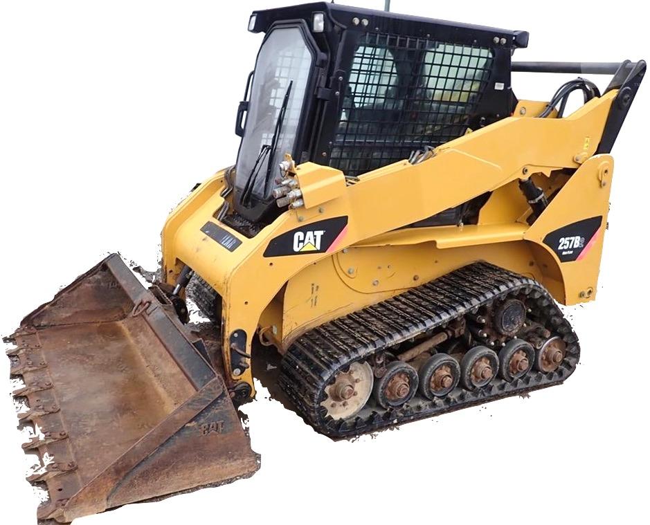
Caterpillar Multi Terrain Loaders 247B, 247B2, 247B3, 257B, 257B2, 257B3 Repair & Service Manual
Caterpillar Multi Terrain Loaders 247B, 247B2, 247B3, 257B, 257B2, 257B3 Repair & Service Manual
Complete official service manual for Caterpillar Multi Terrain Loaders 247B, 247B2, 247B3, 257B, 257B2, 257B3, with all the shop information to maintain, diagnostic, repair, refurbish/rebuild like professional mechanics.
Caterpillar Multi Terrain Loaders 247B, 247B2, 247B3, 257B, 257B2, 257B3 workshop service repair manual includes:
* Numbered table of contents easy to use so that you can find the information you need fast.
* Detailed sub-steps expand on repair procedure information
* Numbered instructions guide you through every repair procedure step by step.
* Troubleshooting and electrical service procedures are combined with detailed wiring diagrams for ease of use.
* Notes, cautions and warnings throughout each chapter pinpoint critical information.
* Bold figure number help you quickly match illustrations with instructions.
* Detailed illustrations, drawings and photos guide you through every procedure.
* Enlarged inset helps you identify and examine parts in detail.
Total Pages: 3,187 pages
File Format: PDF (3,187 pages, bookmarked, Searchable, Printable, high quality)
Language: English
MAIN SECTIONS
Air Inlet And Exhaust System
Basic Engine
Cooling System
Electrical And Starting System
Engine Arrangement
Frame And Body
Fuel System
Hydraulic System
Implements
Lubrication System
Machine Arrangement
Operator Station
Powertrain
Service Equipment And Supplies
Work Tools
Torque Specification
Schematic – Electrical System
Schematic – Hydraulics System
FILE LIST:
KENR8654 - Schematic (216B2, 226B2, 232B2, 236B2 , 242B2, & 252B2 Skid Steer Loader 247B2 & 257B2 Multi-Terrain Loader Electrical System)
KENR8818 - Specifications (247B2 & 257B2 Multi Terrain Loaders Machine Systems)
Axle - Front
Axle - Rear
Bogie Wheel
Control Manifold and Solenoid (Parking Brake)
Control Manifold and Solenoid (Work Tool Positioner)
Control Manifold (High Flow)
Control Manifold (Quick Coupler)
Control Valve (Work Tool)
Coupler Cylinder
Engine Enclosure
Gas Spring Group (Cab)
Gear Motor (Fan) - Demand
Gear Motor (Fan)
Gear Pump - High Flow or Boost Flow
Gear Pump
Hydraulic Oil Filter
Hydraulic Tank
Idler Wheel 1
Idler Wheel 2
Lift Arm Cylinder and Mounting 1
Lift Arm Cylinder and Mounting 2
Lift Cylinder - Left Hand
Lift Cylinder
Lift Cylinder - Right Hand
Machine Frame and Mounting 1
Machine Frame and Mounting 2
Pilot Operated Hydraulic Control 1
Pilot Operated Hydraulic Control 2
Pilot Operated Hydraulic Control - Hydrostatic 1
Pilot Operated Hydraulic Control - Hydrostatic 2
Pilot Operated Hydraulic Control - Hydrostatic
Pilot Operated Hydraulic Control - Work Tool
Piston Motor
Piston Pump
Pump Mounting (Hydrostatic)
Quick Coupler 1
Quick Coupler 2
Radiator and Hydraulic Oil Cooler (Fan)
Radiator and Hydraulic Oil Cooler
Return Manifold
ROPS Mounting
Sprocket
Tilt Cylinder - Left Hand
Tilt Cylinder - Right Hand
Track Drive - Left Hand
Track Drive - Right Hand
Track Tensioner
Undercarriage - Left Hand
Undercarriage - Right Hand
KENR8819 - Systems Operation (247B2 and 257B2 Multi Terrain Loaders Machine Systems)
Control Manifold and Solenoid (Work Tool Positioner) - If Equipped
Control Valve (Work Tool)
General Information
Governor Control
Hydrostatic System
Pilot Hydraulic System
Pilot Valve (Joystick)
Piston Motor (Hydrostatic)
Piston Pump (Hydrostatic)
Undercarriage
Work Tool Hydraulic System
KENR8820 - Testing and Adjusting (247B2 and 257B2 Multi Terrain Loaders Machine Systems)
Accumulator (Pilot) - Test and Charge
Hydraulic Oil Contamination - Test
Hydraulic System Troubleshooting
Hydrostatic System - Flush and Fill
Hydrostatic System - Test and Adjust
Hydrostatic System Troubleshooting
Line Relief Valve - Test and Adjust
Machine Preparation
Main Relief Valve - Test and Adjust
Operational Checks
Pilot System Pressure - Test
Pump Flow - Test
System Pressure - Release
Visual Inspection
Worksheets - Troubleshoot
KENR9408 - Schematic (216B3, 226B3, 236B3, 242B3, 247B3, 252B3, 257B3, 259B3 Skid Steer Loader, Multi-terrain Loader, Compact Track Loader Hydraulic System)
RENR4873 - Disassembly and Assembly (247B and 257B Multi Terrain Loaders Engine Supplement)
Air Cleaner - Remove and Install
Alternator - Remove and Install
Battery and Battery Cable - Separate and Connect
Cab - Tilt
Electric Starting Motor - Remove and Install
Engine Enclosure - Remove and Install
Engine - Install
Engine - Remove
Fuel Filter Group - Remove and Install
Gear Motor (Fan) - Install
Gear Motor (Fan) - Remove
Hydraulic System Pressure - Release
Muffler - Remove and Install
Pump Mounting - Remove and Install
Radiator and Hydraulic Oil Cooler - Install
Radiator and Hydraulic Oil Cooler - Remove
Water Pump - Remove and Install
Water Temperature Regulator - Remove and Install
RENR4874 - Disassembly and Assembly (247B, 247B2, 257B and 257B2 Multi Terrain Loaders Power Train)
Axle (Front) - Remove and Install
Axle (Rear) - Remove and Install
Bogie Axle - Assemble
Bogie Axle - Disassemble
Bogie Axle - Install
Bogie Axle - Remove
Bogie Wheel - Install
Bogie Wheel - Remove
Control Manifold and Solenoid (Parking Brake) - Remove and Install
Heavy Duty Dual Face Seal - Install
Idler Axle - Assemble
Idler Axle - Disassemble
Idler Axle - Install
Idler Axle - Remove
Idler Wheel - Remove and Install
Piston Motor (Hydrostatic) - Assemble
Piston Motor (Hydrostatic) - Disassemble
Piston Motor (Hydrostatic) - Install
Piston Motor (Hydrostatic) - Remove
Piston Pump (Hydrostatic) - Assemble
Piston Pump (Hydrostatic) - Disassemble
Piston Pump (Hydrostatic) - Install
Piston Pump (Hydrostatic) - Remove
System Pressure - Release - Hydraulic
Track Drive - Assemble
Track Drive - Disassemble
Track Drive - Install
Track Drive - Remove
Track (Rubber) - Detension and Tension
Track (Rubber) - Remove and Install
Track Tensioner - Remove and Install
Undercarriage - Remove and Install
RENR4875 - Specifications (247B and 257B Multi Terrain Loaders Machine Systems)
Axle - Front
Axle - Rear
Bogie Wheel
Control Manifold and Solenoid (Parking Brake)
Control Manifold (Quick Coupler)
Control Valve (Work Tool)
Coupler Cylinder
Engine Enclosure
Gas Spring Group (Cab)
Gear Motor (Fan)
Gear Pump - High Flow or Boost Flow
Gear Pump
Hydraulic Oil Filter
Hydraulic Tank
Idler Wheel
Lift Arm Cylinder and Mounting
Lift Cylinder - Left Hand
Lift Cylinder
Lift Cylinder - Right Hand
Machine Frame and Mounting
Motor Mounting (Hydrostatic)
Pilot Operated Hydraulic Control - Hydrostatic
Pilot Operated Hydraulic Control
Pilot Operated Hydraulic Control - Work Tool
Piston Motor
Piston Pump
Pump Mounting (Hydrostatic)
Quick Coupler
Radiator and Hydraulic Oil Cooler (Fan)
Radiator and Hydraulic Oil Cooler
Return Manifold
ROPS Mounting
Sprocket
Tilt Cylinder - Left Hand
Tilt Cylinder - Right Hand
Track Drive - Left Hand
Track Drive - Right Hand
Track Tensioner
Undercarriage - Left Hand
Undercarriage - Right Hand
RENR4876 - Systems Operation (247B and 257B Multi Terrain Loaders Machine Systems)
Control Manifold and Solenoid (Work Tool Positioner) - If Equipped
Control Valve (Work Tool)
General Information
Governor Control
Hydrostatic System
Pilot Hydraulic System
Pilot Valve (Joystick)
Piston Motor (Hydrostatic)
Piston Pump (Hydrostatic)
Undercarriage
Work Tool Hydraulic System
RENR4877 - Testing and Adjusting (247B and 257B Multi Terrain Loaders Machine Systems)
Accumulator (Pilot) - Test and Charge
Hydraulic Oil Contamination - Test
Hydraulic System Troubleshooting
Hydrostatic System - Flush and Fill
Hydrostatic System - Test and Adjust
Hydrostatic System Troubleshooting
Line Relief Valve - Test and Adjust
Machine Preparation
Main Relief Valve - Test and Adjust
Operational Checks
Pilot System Pressure - Test
Pump Flow - Test
System Pressure - Release
Visual Inspection
Worksheets - Troubleshoot
RENR4878 - Disassembly and Assembly (247B, 247B2, 257B and 257B2 Multi Terrain Loaders Machine Systems)
Accumulator - Remove and Install
Air Conditioner and Heater - Assemble
Air Conditioner and Heater - Disassemble
Air Conditioner and Heater - Install
Air Conditioner and Heater - Remove
Cab - Install
Cab - Remove
Cab - Tilt
Control Valve (Work Tool) - Assemble
Control Valve (Work Tool) - Disassemble
Control Valve (Work Tool) - Install
Control Valve (Work Tool) - Remove
Coupler Cylinder - Remove and Install
Disconnecting Snap To Connect Fittings
Diverter Valve - Install
Diverter Valve - Remove
Gas Spring - Remove and Install
Gear Motor - Assemble
Gear Motor - Disassemble
Gear Motor - Install
Gear Motor - Remove
Gear Pump - Assemble
Gear Pump - Disassemble
Gear Pump - Install
Gear Pump - Remove
Hydraulic System Pressure - Release
Hydraulic Tank - Install
Hydraulic Tank - Remove
Lift Arms - Install
Lift Arms - Remove
Lift Cylinder - Install
Lift Cylinder - Remove
Pilot Operated Hydraulic Control - Assemble
Pilot Operated Hydraulic Control - Disassemble
Pilot Operated Hydraulic Control - Install
Pilot Operated Hydraulic Control - Remove
Quick Coupler - Remove and Install
Refrigerant Accumulator - Remove and Install
Refrigerant Compressor and Support Housing - Remove and Install
Refrigerant Condenser and Mounting - Remove and Install
Seat - Remove and Install
Solenoid Valve and Mounting (Coupler) - Remove and Install
Solenoid Valve (Compressor Motor) - Remove and Install
Tilt Cylinder - Install
Tilt Cylinder - Remove
Window Wiper Motor - Remove and Install
RENR4889 - Schematic (247B, 247B2, 257B, 257B2, 267B, 277B, 287B Multi Terrain Loaders Hydraulic System)
RENR6417 - Systems Operation (247B, 257B, 267B, 277B & 287B Multi Terrain Loaders & 216B, 226B, 232B, 236B, 242B, 246B, 248B, 252B, 262B & 268B Skid Steer Loaders Interlock Electronic Control System)
Diagnostic Operation
Electronic Control Module (ECM)
Engine Start Interlock
General Information
Hydrostatic System Interlock and Parking Brake Interlock
Indicators
Normal Operation
Related Components
Relays
Solenoid Valve
Switches
Work Tool Interlock
RENR6417 - Testing & Adjusting (247B, 257B, 267B, 277B & 287B Multi Terrain Loaders & 216B, 226B, 232B, 236B, 242B, 246B, 248B, 252B, 262B & 268B Skid Steer Loaders Interlock Electronic Control System)
Electronic Control Module (ECM) - Replace
Glossary of Electrical Terms
System Schematic
RENR6417 - Troubleshooting (247B, 257B, 267B, 277B & 287B Multi Terrain Loaders & 216B, 226B, 232B, 236B, 242B, 246B, 248B, 252B, 262B & 268B Skid Steer Loaders Interlock Electronic Control System)
Armrest Indicator Is Flashing
Charging System
Electrical Component and Connector Locations
Electrical System
Engine Does Not Crank
General Information
Initial Troubleshooting Procedure
Parking Brake Indicator and Armrest Indicator Are Flashing
Parking Brake Indicator and Armrest Indicator Do Not Function Correctly
Parking Brake Indicator Is Flashing
Parking Brake Intermittent
Service Tools
Solenoid Valve (Parking Brake) Does Not Function Correctly
Switch (Hydraulic Lockout)
Switch (Parking Brake)
Work Tool Does Not Function
RENR6418 - Systems Operation (247B, 257B, 267B, 277B & 287B Multi Terrain Loaders & 216B, 226B, 232B, 236B, 242B, 246B, 248B, 252B, 262B & 268B Skid Steer Loaders Auxiliary Hydraulic Electronic Control System)
Cat Data Link
Electronic Control Module (ECM)
General Information
Indicators
Normal Operation
Related Components
Sensors
Solenoid Valves
Switches
RENR6418 - Testing & Adjusting (247B, 257B, 267B, 277B & 287B Multi Terrain Loaders & 216B, 226B, 232B, 236B, 242B, 246B, 248B, 252B, 262B & 268B Skid Steer Loaders Auxiliary Hydraulic Electronic Control System)
Electrical Connector - Inspect
Electronic Control Module (ECM) - Flash Program
Electronic Control Module (ECM) - Replace
Glossary of Electrical Terms
System Schematic
Wiring Harness (Open Circuit) - Test
Wiring Harness (Short Circuit) - Test
RENR6418 - Troubleshooting (247B, 257B, 267B, 277B & 287B Multi Terrain Loaders & 216B, 226B, 232B, 236B, 242B, 246B, 248B, 252B, 262B & 268B Skid Steer Loaders Auxiliary Hydraulic Electronic Control System)
Auxiliary Hydraulic Does Not Function in Either Direction
Auxiliary Hydraulic Does Not Function in One Direction
Diagnostic Capabilities
Diagnostic Code List
Electrical Component and Connector Locations
General Information
High Flow Does Not Function in Either Direction
High Flow Does Not Function in One Direction
Power Supply Circuit of Electronic Control Module
Service Tools
Switch (Armrest) and Switch (Seat)
Switch (Continuous Flow)
Switch (Hydraulic Lockout)
Switch (Interlock Override)
Switch (Parking Brake)
Switch (Two Speed)
Using Caterpillar Electronic Technician to Determine Diagnostic Codes
RENR6419 - Schematic (216B, 216B2, 226B, 226B2, 232B, 232B2, 236B, 236B2, 242B, 242B2, 246B, 248B, 252B, 252B2, 262B, 268B & 247B, 247B2, 257B, 257B2, 267B, 277B, 287B Loaders Electrical System)
RENR8751 - Schematic (247B, 247B2, 257B, 257B2, 267B, 277B, and 287B Multi-Terrain Loader Hydraulic System)
RENR8752 - Schematic (257B Multi Terrain Loader Hydraulic System)
RENR8753 - Schematic (257B Multi Terrain Loader Hydraulic System)
UENR0251 - Disassembly & Assembly (259B3 Compact Track Loader & 247B3, 257B3 Multi Terrain Loaders & 216B3, 226B3, 236B3, 242B3, 252B3 Skid Steer Loaders Power Train)
Axle - Assemble - Heavy Duty
Axle - Assemble
Axle - Disassemble - Heavy Duty
Axle - Disassemble
Axle (Front) - Remove and Install
Axle - Install
Axle (Rear) - Remove and Install
Axle - Remove
Bogie Axle - Assemble
Bogie Axle - Disassemble
Bogie Axle - Install
Bogie Axle - Remove
Bogie Wheel - Install
Bogie Wheel - Remove
Chain (Drive) - Install
Chain (Drive) - Remove
Chain (Drive) Tension - Adjust
Control Manifold and Solenoid (Parking Brake) - Remove and Install
Heavy Duty Dual Face Seal - Install
Idler - Assemble - Front
Idler - Assemble - Rear
Idler Axle - Assemble
Idler Axle - Disassemble
Idler Axle - Install
Idler Axle - Remove
Idler - Disassemble - Front
Idler - Disassemble - Rear
Idler - Install - Front
Idler - Install - Rear
Idler - Remove - Front
Idler - Remove - Rear
Idler Wheel - Remove and Install
Piston Motor (Hydrostatic) - Assemble - CTL
Piston Motor (Hydrostatic) - Assemble - Final Drive Bench Method
Piston Motor (Hydrostatic) - Assemble
Piston Motor (Hydrostatic) - Assemble - Two Speed
Piston Motor (Hydrostatic) - Disassemble - CTL
Piston Motor (Hydrostatic) - Disassemble - Final Drive Bench Method
Piston Motor (Hydrostatic) - Disassemble
Piston Motor (Hydrostatic) - Disassemble - Two Speed
Piston Motor (Hydrostatic) - Install
Piston Motor (Hydrostatic) - Remove
Piston Pump (Hydrostatic) - Assemble
Piston Pump (Hydrostatic) - Disassemble
Piston Pump (Hydrostatic) - Install
Piston Pump (Hydrostatic) - Remove
Recoil Spring and Track Adjuster - Install
Recoil Spring and Track Adjuster - Remove
Recoil Spring - Assemble
Recoil Spring - Disassemble
Solenoid Valve and Mounting (Parking Brake) - Remove and Install - Two Speed
Sprocket - Remove and Install
System Pressure - Release - Hydraulic
Tire and Rim - Remove and Install
Track - Detension and Tension
Track Drive - Assemble
Track Drive - Disassemble
Track Drive - Install
Track Drive - Remove
Track - Remove and Install
Track Roller - Remove and Install
Track (Rubber) - Detension and Tension
Track (Rubber) - Remove and Install
Track Tensioner - Remove and Install
Undercarriage - Install
Undercarriage - Remove and Install
Undercarriage - Remove
UENR0252 - Disassembly & Assembly (259B3 Compact Track Loader & 247B3, 257B3 Multi Terrain Loaders & 216B3, 226B3, 236B3, 242B3, 252B3 Skid Steer Loaders Machine Systems)
Accumulator - Remove and Install
Air Conditioner and Heater - Assemble
Air Conditioner and Heater - Disassemble
Air Conditioner and Heater - Install
Air Conditioner and Heater - Remove
Cab - Install
Cab - Remove
Cab - Tilt
Control Valve (Work Tool) - Assemble
Control Valve (Work Tool) - Disassemble
Control Valve (Work Tool) - Install
Control Valve (Work Tool) - Remove
Coupler Cylinder - Remove and Install
Diverter Valve - Remove and Install
Gas Spring - Remove and Install - Extended Reach
Gear Motor - Assemble
Gear Motor - Disassemble
Gear Motor - Install
Gear Motor - Remove
Gear Pump - Assemble - High Flow
Gear Pump - Assemble
Gear Pump - Disassemble - High Flow
Gear Pump (Implement and Charge) - Assemble
Gear Pump (Implement and Charge) - Disassemble
Gear Pump - Install
Gear Pump - Remove
Hydraulic Tank - Install
Hydraulic Tank - Remove
Lift Arms - Install - Extended Reach Machines
Lift Arms - Install - Radial Arc Machines
Lift Arms - Remove - Extended Reach Machines
Lift Arms - Remove - Radial Arc Machines
Lift Cylinder - Remove and Install - Extended Reach Machines
Lift Cylinder - Remove and Install - Radial Arc Machines
Pilot Operated Hydraulic Control - Assemble
Pilot Operated Hydraulic Control - Disassemble
Pilot Operated Hydraulic Control - Install
Pilot Operated Hydraulic Control - Remove
Quick Coupler - Remove and Install
Refrigerant Accumulator - Remove and Install
Refrigerant Compressor and Support Housing - Remove and Install
Refrigerant Compressor - Remove and Install
Refrigerant Condenser - Remove and Install
Seat - Remove and Install
Solenoid Valve and Mounting (Coupler) - Remove and Install
Solenoid Valve (Compressor Motor) - Remove and Install
System Pressure - Release - Hydraulic
Tilt Cylinder - Remove and Install
Window Wiper Motor - Remove and Install
UENR0254 - Schematic (216B3, 226B3, 236B3, 242B3, 252B3 Skid Steer Loader & 247B3, 257B3 Multi-Terrain Loader & 259B3 Compact Track Loader Electrical System)
UENR0255 - Systems Operation (259B3 Compact Track Loader, 247B3, 257B3 Multi Terrain Loaders & 216B3, 26B3, 236B3, 242B3, 252B3 Skid Steer Loaders Machine Electronic Control System)
Electrical Input Components
Electrical Output Components
Electronic Control Module
Features
General Information
Location of Electrical Components
UENR0255 - Testing & Adjusting (259B3 Compact Track Loader, 247B3, 257B3 Multi Terrain Loaders & 216B3, 26B3, 236B3, 242B3, 252B3 Skid Steer Loaders Machine Electronic Control System)
Calibration
Electrical Connector - Inspect
Electronic Control Module (ECM) - Flash Program
Electronic Control Module (ECM) - Replace
System Schematic
Wiring Harness (Open Circuit) - Test
Wiring Harness (Short Circuit) - Test
UENR0255 - Troubleshooting (259B3 Compact Track Loader, 247B3, 257B3 Multi Terrain Loaders & 216B3, 26B3, 236B3, 242B3, 252B3 Skid Steer Loaders Machine Electronic Control System)
Connector Locations
Diagnostic Capabilities
Diagnostic Code List
Emerging Symptom Information
General Information
Indicator Lamp Does Not Illuminate During the Power Up Self Test
Indicator Lamp Is On Continuously
...
Power Supply Circuit of Electronic Control Module
Service Tools
Starting System
Switch Circuits
Symptom Troubleshooting
Using Caterpillar Electronic Technician to Determine Diagnostic Codes
UENR2643 - Schematic (216B3, 226B3, 236B3, 242B3, 252B3 Skid Steer Loader & 247B3, 257B3 Multi-Terrain Loader & 259B3 Compact Track Loader Electrical System)
UENR3951 - Schematic (216B3, 226B3, 236B3, 242B3, 247B3, 252B3, 257B3, 259B3 Skid Steer Loader, Multi-terrain Loader, Compact Track Loader Hydraulic System)
UENR3952 - Schematic (216B3, 226B3, 236B3, 242B3, 247B3, 252B3, 257B3, 259B3 Skid Steer Loader, Multi-terrain Loader, Compact Track Loader Hydraulic System)
![]()