
John Deere Combines 9560 STS, 9660 STS, 9760 STS, 9860 STS Repair Service Manual (TM2181)
Complete service repair manual for John Deere Combines 9560 STS, 9660 STS, 9760 STS, 9860 STS (North American), with workshop information to maintain, repair, and service like professional mechanics.
John Deere Combines 9560 STS, 9660 STS, 9760 STS, 9860 STS workshop service repair manual includes:
* Numbered table of contents easy to use so that you can find the information you need fast.
* Detailed sub-steps expand on repair procedure information
* Numbered instructions guide you through every repair procedure step by step.
* Notes, cautions and warnings throughout each chapter pinpoint critical information.
* Bold figure number help you quickly match illustrations with instructions.
* Detailed illustrations, drawings and photos guide you through every procedure.
* Enlarged inset helps you identify and examine parts in detail.
TM2181 - John Deere Combines 9560 STS, 9660 STS, 9760 STS, 9860 STS Technical Manual (Repair).pdf
TM2181 - John Deere Combines 9560 STS, 9660 STS, 9760 STS, 9860 STS Technical Manual (Repair).epub
Total Pages: 2,219 pages
File Format: PDF/EPUB/MOBI/AZW (PC/Mac/Android/Kindle/iPhone/iPad; bookmarked, ToC, Searchable, Printable)
Language: English
MAIN SECTIONS
Foreword
General
Safety
Specifications
Tune-Up and Adjustment
Fuels and Lubricants
Engine
Remove and Install Engine
Cooling System
Lower Engine Repair
Fuel and Air Repair
Air Intake System
Diesel Fuel System
Electrical System
Batteries
Harness and Connector Repair
Wire Harness Routing
Fuses, Circuit Breakers and Relays
Lighting
Operators Station
Sensors and Switches
Wiper
Alternator
Starting Motor
Electrical Engine Control
GREENSTAR Components
Power Train Repair
Transmission and Differential
Single Reduction Final Drive-Heavy Duty
Hydrostatic System
Cam Lobe Motor
Tires and Wheels
Power Steering and Brakes
Steering
Brakes
Hydraulic Repair
Hydraulic Reservoir
Hydraulic Pumps
Hydraulic Valves
Hydraulic Valve Stack (S.N. -715300)
Hydraulic Valve Stack (S.N. 715301-)
Hydraulic Cylinders
Motors
Accumulator
Separator Shell
Gull Wing Doors
Operator Station Repair
Air Conditioning System (R134a)
System Components
Cab
Feeder House Repair
Conveyor
Top Shaft and Slip Clutch
Feeder House Drives and Reverser Gear Case
CONTOUR MASTER Tilt Cylinder
CONTOUR MASTER Tilt Frame
Separator
Separator Repair
Separator Drives
Residue Disposal
Conveyor Augers, Cleaning Fan And Chaffer And Sieve Frame
Tailings Elevator and Augers
Primary Countershaft Gear Case
Header Electromagnetic Clutch
Grain Tank and Unloading System Repair
Grain Tank Cross Augers
Unloading Auger System Drives
Vertical Unloading Auger and Lower Gear Case
Horizontal Unloading Auger and Gear Case
Clean Grain Elevator
Grain Tank and Extensions
Engine Gear Case and Control Valve Repair
Engine Gear Case and Valve
Dealer Fabricated Tools
Dealer Fabricated Tools
tm2181 - 9560 STS™, 9660 STS™, 9760 STS™ and 9860 STS™ Combine Repair
Table of Contents
Foreword
Section 10: General
Group 05: Safety
Recognize Safety Information
Understand Signal Words
Handle Fluids Safely—Avoid Fires
Prevent Battery Explosions
Handling Batteries Safely
Prepare for Emergencies
Prevent Acid Burns
Handle Chemical Products Safely
Avoid High-Pressure Fluids
Service Accumulator Systems Safely
Wait Before Opening High-Pressure Fuel System
Park Machine Safely
Support Machine Properly
Wear Protective Clothing
Work in Clean Area
Service Machines Safely
Work In Ventilated Area
Illuminate Work Area Safely
Replace Safety Signs
Use Proper Lifting Equipment
Remove Paint Before Welding or Heating
Avoid Heating Near Pressurized Fluid Lines
Service Tires Safely
Avoid Harmful Asbestos Dust
Practice Safe Maintenance
Construct Dealer-Made Tools Safely
Use Proper Tools
Decommissioning — Proper Recycling and Disposal of Fluids and Components
Use Adequate Service Facilities
Live With Safety
Group 10: Specifications
Ground Speeds (Fast Idle) Two Speed Four Wheel Drive
Turning Radius
Operating Speeds—9560 STS
Specifications—9560 STS Combine
Dimensions—9560 STS Combine
Dimension Reference Points—9560 STS Combine
Operating Speeds—9660 STS, 9760 STS Combines
Specifications—9660 STS Combine
Specifications—9760 STS Combine
Dimensions—9660 STS, 9760 STS Combines
Dimension Reference Points—9660 STS, 9760 STS Combines
Operating Speeds—9860 STS Combine
Specifications—9860 STS Combine (S.N. —715700)
Specifications—9860 STS Combine (S.N. 715701—)
Dimensions—9860 STS Combine
Dimension Reference Points—9860 STS Combine
Metric Bolt and Screw Torque Values
Unified Inch Bolt and Screw Torque Values
Sealants and Adhesives Cross-Reference Chart
Face Seal Fittings Assembly and Installation—All Pressure Applications
Metric Face Seal Fitting Torque Chart—Standard Pressure Applications
Metric Face Seal Fitting Torque Chart—High Pressure Applications
SAE Face Seal Fitting Torque Chart—Standard Pressure Applications
SAE Face Seal Fitting Torque Chart—High Pressure Applications
Four Bolt Flange Fittings Assembly and Installation—All Pressure Applications
SAE Four Bolt Flange Cap Screw Torque Values—Standard Pressure Applications
SAE Four Bolt Flange Cap Screw Torque Values—High Pressure Applications
External Hexagon Port Plug Torque Chart
Prevent Hydraulic System Contamination
Check Oil Lines and Fittings
Basic Electrical Component Handling / Precautions For Vehicles Equipped With Computer Controlled Systems
Group 15: Tune-Up and Adjustment
Tune-Up and Adjustment
Care and Maintenance of Belts
Defective Belts
Group 20: Fuels and Lubricants
Handle Fuel Safely—Avoid Fires
Handling and Storing Diesel Fuel
Diesel Fuel
BioDiesel Fuel
Lubricity of Diesel Fuel
Testing Diesel Fuel
Diesel Engine Coolant (engine with wet sleeve cylinder liners)
Operating in Warm Temperature Climates
Supplemental Coolant Additives
Additional Information About Diesel Engine Coolants and John Deere LIQUID COOLANT CONDITIONER
Testing Diesel Engine Coolant
Diesel Engine Break-In Oil — Non-Emissions Certified and Certified Tier 1, Tier 2, Tier 3, Stage I, Stage II, and Stage III
Diesel Engine Oil — Tier 2 and Stage II
Oilscan™ and CoolScan™
Hydrostatic Drive System, Main Hydraulic System and Main Engine Gear Case Oils
Transmission, Final Drives, Loading Auger, Primary Countershaft and Two-Speed Separator Drive Gear Cases
Grease
Brake Fluid
Lubricant Storage
Alternative and Synthetic Lubricants
Mixing of Lubricants
Section 20: Engine
Group 05: Remove and Install Engine
Essential or Recommended Tools
Specifications
John Deere Engine Repair
Remove Engine—6.8 L
Install Engine—6.8 L
Remove Engine—8.1 L
Install Engine—8.1 L
Remove Engine—9.0 L
Install Engine—9.0 L
Remove Engine—12.5 L
Install Engine—12.5 L
Group 10: Cooling System
Essential or Recommended Tools
Specifications
John Deere Engine Repair
Rotary Screen Drive
Rotary Screen Idler Arm and Sheaves
Remove and Install Upper and Lower Air Scoops
Remove and Install Rotary Screen
Adjusting Rotary Screen Knife Comb
Remove Radiator—6.8 L Engine
Install Radiator—6.8 L Engine
Remove Radiator—8.1 L Engine
Install Radiator—8.1 L Engine
Remove Radiator—9.0 L Engine
Install Radiator—9.0 L Engine
Remove Radiator—12.5 L Engine
Install Radiator—12.5 L Engine
Test Radiator
Test Radiator Cap
Replace Thermostats
Repair or Replace Water Pump
Group 15: Lower Engine Repair
Remove and Install Engine Oil Pan Access Sheet
Section 30: Fuel and Air Repair
Group 05: Air Intake System
Other Material
Specifications
John Deere Engine Repair
Remove and Install Turbocharger—8.1 L Engine
Remove and Install Turbocharger—6.8 L and 9.0 L Engine
Remove and Install Turbocharger—12.5 L Engine
Turbocharger Repair
Remove and Install Charge Air Cooler—8.1 L Engine
Remove and Install Charge Air Cooler—6.8 L and 9.0 L Engine
Remove and Install Charge Air Cooler—12.5 L Engine
Cleaning the Charge Air Cooler
Group 10: Diesel Fuel System
Other Material
Specifications
Bleeding Fuel System 8.1 L 9660 (S.N. —705934), 9760 (S.N. —705758)
Bleeding Fuel System 8.1 L Dual Filter System 9660 (S.N. 705935—), 9760 (S.N. 705759—)
Bleed Fuel System—12.5 L Engine
Remove and Install Fuel Return Line Regulator 9560 (S.N. —710250), 9660 (S.N. —710500) 9760 (S.N. —710600), 9860 (S.N. —710700)
Remove and Install Fuel Tank
Remove and Install Fuel Tank Shut-Off Valve and Drain Valve
Remove and Install Fuel Tank Strainer and Breather
Replace Cold Weather Starting Aid Can
Remove and Install Cold Weather Starting Aid
Section 40: Electrical System
Group 05: Batteries
Prevent Battery Explosions
Handling Batteries Safely
Prevent Damage to Electrical Systems
Checking Electrolyte Specific Gravity
Battery Replacement
Remove and Install Batteries
Connecting Booster Batteries
Charging Batteries
Connecting Battery Cables
Group 10: Harness and Connector Repair
Essential or Recommended Tools
Other Material
Use Electrical Insulating Compound
Using High-Pressure Washers
Electrical System Visual Inspection
Basic Electrical Component Handling / Precautions for Vehicles Equipped with Computer Controlled Systems
Electrical Connector / Wiring Harness Handling and Repair
Repair Procedure R-A
Repair Procedure R-B
Repair Procedure R-C
Repair Procedure R-D
Repair Procedure R-E
Repair Procedure R-F
Repair Procedure R-G
Repair Procedure R-I
Repair Procedure R-J
Repair Procedure R-K
Repair Procedure R-M
Repair Procedure R-N
Repair Procedure R-AE
Group 15: Wire Harness Routing
Replace Harness
Cab Main Wiring Harness (S.N. —715300)
Cab Main Wiring Harness (S.N. 715301—)
Auxiliary Cab Main AUTOTRAC Wiring Harness (S.N. —715300)
Auxiliary Cab Main AutoTrac Wiring Harness (S.N. 715301—)
Left-Hand Main Wiring Harness
Left-Hand Main Wiring Harness (Tier III Cooling Package)
Right-Hand Main Wiring Harness
Right-Hand Main Wiring Harness (Tier III Cooling Package)
Engine Wiring Harness
Engine Wiring Harness (Tier III Cooling Package)
Group 20: Fuses, Circuit Breakers and Relays
Specifications
Basic Operation
Power Distribution Board System Basic Description
Circuit Board Replacement
Relays
Power Distribution Board Relay Identification
Engine Compartment Relay Panel Fuse Identification
Engine Compartment Relay Panel Identification
Group 25: Lighting
Safety Rules When Replacing Halogen Bulbs
Bulb Part Numbers
Cab Head Light Bulb Replacement and Adjustment (S.N. —715300)
Cab Head Light Bulb Replacement and Adjustment (S.N. 715301—)
Remove and Install High Intensity Discharge (HID-Xenon) Lights (Optional) (S.N. —715300)
Remove and Install High Intensity Discharge (HID-Xenon) Lights (Optional) (S.N. 715301—)
Remove and Install High Intensity Discharge (HID-Xenon) Ballasts (S.N. 715301—)
Auxiliary Field, Access Door, Grain Tank, Unload Auger and Work Light Bulb Replacement
Side Finder (Optional) Light Bulb Replacement
Front Turn Signal, Tail and Side Light Bulb Replacement
Harzard/Warning Light Bulb Replacement
Cleaning Shoe Light Bulb Replacement
Turn Signal Light Bulb Replacement
Dome and Console Light Bulb Replacement
CommandTouch Cornerpost Monitor Light Bulb Replacement
Warning Display Panel Light Bulb Replacement
Group 30: Operators Station
Other Material
Specifications
Instruments and Controls Identification
Overhead Warning Display Panel
Remove and Install Overhead Warning Display Panel
Replace Overhead Warning Display Panel Circuit Board
Remove and Install Light Panel Dimmer Switch
Remove and Install Overhead Display Rocker Switches
Remove and Install ClimaTrak Automatic Air Conditioning/Heater Temperature Control Switch and Fan Switch
Remove and Install Radio
Remove and Install Radio Speaker (S.N. —715300)
Remove and Install Radio Speaker (S.N. 715301—)
Remove and Install Radio Antenna (S.N. —715300)
Remove and Install Radio Antenna (S.N. 715301—)
Replace Cornerpost Main Circuit Board
Remove Header Control Module
Remove Automatic Combine Adjustment (ACA) Display
Remove Performance Monitor and Digital Tachometer Module
CommandTouch Console Controls
Remove and Install CommandTouch Console
Remove and Install Header and Separator Engage Switches
Remove and Install Dial-A-Speed and Active Header Control Switches
Remove and Install Backlight Bulbs for Dial-A-Speed and Active Header Control Switches
Remove and Install CommandTouch Console Membrane Switches
Remove and Install CommandTouch Console Circuit Board
Replace Neutral Safety Switch
Replace Mini Harness
Remove and Install Multi-Function Handle
Remove and Install Start Switch
Remove and Install Starting Aid Switch
Remove and Install Turn Signal/Side Finder Light Switch
Remove and Install Horn Switch
Remove and Install Remote Mirrors (Optional)
Remove and Install Remote Mirror Switch (S.N. —715300) (Optional)
Remove and Install Remote Mirror Switch (S.N. 715301—) (Optional)
Group 35: Sensors and Switches
Essential or Recommended Tools
Other Material
Specifications
Shaft Speed Sensor Locations
Shaft Speed Sensor Locations
Remove and Install Ground Speed Sensor
Remove And Install Low Shaft Speed Sensor
Remove and Install STS Rotor Speed Sensor
Remove and Install Full Grain Tank Sensor
Remove and Install Tailings Sensor
Remove and Install (Shoe/Separator) VisionTrak VisionTrak is a trademark of Deere & Company Sensors
Remove and Install Concave Position Sensor
Remove and Install Header Height and Lateral Tilt Control Sensors
Remove and Install Multi-Function Handle Feed Rate Sensor
Remove and Install Hydraulic Reservoir Temperature Sensor
Remove and Install Hydraulic Reservoir Temperature Sensor (Tier III Cooling Package)
Remove and Install Coolant Temperature Sensor
Remove and Install Coolant Temperature Sensor (Tier III Cooling Package)
Remove and Install Fuel Level Sensor
Remove and Install Park Brake Switch
Remove and Install Air Filter Restriction Switch
Remove and Install Air Filter Restriction Switch (Tier III Cooling Package)
Remove and Install Fuel Pressure Switch
Remove and Install Engine Gear Case Temperature and Pressure Switches
Remove and Install Hydro Charge Pressure Switch
Remove and Install Engine Oil Pressure Switch
Remove and Install Compressor Inlet Temperature Sensor—9.0 L
Remove and Install Camshaft Position Sensor—9.0 L
Remove and Install Crankshaft Position Sensor—9.0 L
Remove and Install Exhaust Gas Recirculation (EGR) Exhaust Gas Temperature, Fresh Air Temperature and Exhaust Manifold Pressure Sensors—9.0 L
Remove and Install Intake Manifold Pressure and Exhaust Gas Recirculation (EGR) Mixed Gas Temperature Sensor—9.0 L
Remove and Install Turbocharger Speed Sensor—9.0 L
Remove and Install Fuel Rail Pressure Sensor—9.0 L
Remove and Install Switches in the Ground Level Switch Bank
Remove and Install Back-Up Alarm Switch
Back-Up Alarm (S.N. —715300)
Back-Up Alarm—9860 (S.N. 715301—)
Back-Up Alarm—9560, 9660, 9760 (S.N. 715301—)
Group 40: Wiper
Specifications
Remove and Install Wiper Motor
Adjust Windshield Wiper
Remove and Install Windshield Washer (S.N. —715300)
Remove and Install Windshield Washer (S.N. 715301—)
Group 45: Alternator
Essential or Recommended Tools
Specifications
John Deere Engine Accessories—Alternator Repair—Use CTM77
Remove and Install Alternator and Alternator Belt
Remove and Install Voltage Regulator (185 Amp Leece-Neville)
Remove and Install Alternator Pulley (200 Amp Bosch)
Group 50: Starting Motor
Essential or Recommended Tools
Specifications
John Deere Starting Motor Repair—Use CTM77
Remove and Install Starting Motor
Group 55: Electrical Engine Control
Electronic Governor and Speed Controller Repair
Group 60: GREENSTAR Components
Specifications
Other Material
Remove and Install GREENSTAR Mass-Flow Sensor
Remove and Install GREENSTAR Moisture Sensor
Disassemble and Assemble GREENSTAR Moisture Sensor
Remove and Install GREENSTAR Moisture Sensor Actuator
Remove and Install GREENSTAR Moisture Sensor Circuit Board
Remove and Replace GREENSTAR Moisture Sensor Lower Cell Assembly
Disassemble and Assemble Position Receiver
Remove and Install Position Receiver
Section 50: Power Train Repair
Group 05: Transmission and Differential
Other Material
Specifications
Remove and Repair Shifter Forks and Shifter Cam
Install Shifter Forks and Shifter Cam
Remove and Install Transmission Lube Pump
Remove and Install Suction Screen
Remove Transmission
Transmission Components
Transmission Recondition
Disassemble and Repair Transmission
Assemble Transmission
Install Transmission
Remove and Install Gearshift Lever and Linkage
Adjust Gearshift Linkage
Group 10: Single Reduction Final Drive—Heavy Duty
Essential Tools or Recommended Tools
Service Equipment and Tools
Other Material
Specifications
Remove and Install Final Drive
Disassemble and Assemble Final Drive
Adjust Spindle Bearing
Group 15: Hydrostatic System
Essential or Recommended Tools
Service Equipment and Tools
Other Material
Specifications
Serial Number Plate
Clean Hydrostatic Motor and Pump
Flushing the Hydrostatic System
Remove and Install Hydrostatic Motor
Disassemble Hydrostatic Motor
Inspect Parts
Lack of Lubrication
Abrasive Contamination
Cavitation
Over Speeding
Inspect Shaft Seal
Inspect Thrust Plate
Inspect Fixed Swashplate
Inspect Piston Slipper
Inspect Piston Retainer
Inspect Cylinder Block
Inspect Bearing Plate
Inspect Valve Plate
Inspect Bearing and Race
Inspect Servo Piston
Inspect Drive Shaft
Replace Cylinder Block Spring
Assemble Motor
Remove and Install Motor Valve Block (Manifold)
Repair Motor Valve Block
Remove Hydrostatic Pump
Disassemble Hydrostatic Drive Pump
Assemble Hydrostatic Drive Pump
Replace High-Pressure Line Center Pivot O-Rings
Disassemble and Assemble End Cover
Repair Displacement Control Valve
Disassemble and Assemble DisplacementControl Valve with Feed Rate (Optional)
Electronic Proportional Displacement Control Valve Neutral Adjustment
Install Hydrostatic Pump
Remove and Install Charge Pump
Repair Charge Pump
Remove and Install Control Cable
Adjust Hydrostatic Neutral Linkage
Adjust Mechanical Displacement Control Valve Neutral
Start-Up Procedure After Hydrostatic System Repair
Group 20: Cam Lobe Motor
Essential or Recommended Tools
Service Equipment and Tools
Other Material
Specifications
Flushing Cam Lobe Motors
Remove Cam Lobe Motor
Install Cam Lobe Motor
Remove and Install Cam Lobe Motor Control Valve
Disassemble and Assemble Cam Lobe Motor Control Valve
Remove and Install Steering Yoke
Disassemble and Assemble Pivot Pins, Bushings, and Seals
Remove and Install Solenoid Valve and Valve Block
Remove and Install Displacement Control Valve
Remove and Install Cam and Piston Carrier
Remove and Install Stack Valve Seals
Remove and Install Axle Bearings and Seals—Style A
Remove and Install Axle Bearings and Seals—Style B
Group 25: Tires and Wheels
Essential or Recommended Tools
Service Equipment and Tools
Specifications
Service Tires Safely
Care and Service of Tires
Using Liquid Weight
Jacking Locations
Remove and Install Tire
Drive Wheel Bolt Torque
Dual Wheels Bolt Torque
Rear Wheel Bolt Torque
Install Axle Extension Tubes
Install Dual Wheels and Truss Rod
Section 60: Power Steering and Brakes
Group 05: Steering
Essential or Recommended Tools
Service Equipment and Tools
Other Material
Specifications
Steering Pump Repair
Remove Steering Valve
Steering Valve
Disassemble Steering Valve
Assemble Steering Valve
Install Steering Valve
Electro-Hydraulic Steering Valve and Flowmeter—Exploded View
Remove and Install Flow Meter
AUTOTRAC Assisted Steering Flowmeter—Exploded View
Steering Column Components
Disassemble And Assemble Steering Column
Replace Telescoping Shaft Bearings
Remove and Install Steering Cylinder
Disassemble And Assemble Steering Cylinder
Toe-In Adjustment
Remove and Install Steering Tie Rod Joint
Remove And Install Tie Rod End
Remove and Install Rear Spindle Assembly—Non-Powered
Disassemble and Assemble Rear Spindle Assembly—Non-Powered
Remove and Install Rear Axle Pivot Bushings
Rear Axle Adjustment
Group 10: Brakes
Service Equipment and Tools
Other Material
Specifications
Deglazing Brake Linings
Remove Brake Drum
Remove Brake Shoe
Repair Brakes
Assemble Brakes
Install Brake Drum
Remove and Install Master Cylinder
Disassemble and Assemble Master Cylinder (Double Bleed Screw)
Brake Fluid Reservoir
Adjusting Master Cylinder
Bleeding Brake System—Double Bleed Screw
Remove and Install Slave Cylinders
Disassemble and Assemble Slave Cylinder
Disassemble and Assemble Brake Pedals
Disassemble and Assemble Parking Brake Pedal
Adjust Park Brake Pedal
Section 70: Hydraulic Repair
Group 05: Hydraulic Reservoir
Essential or Recommended Tools
Other Material
Specifications
Remove and Install Reservoir (S.N. —715300)
Remove and Install Reservoir (S.N. 715301—)
Flushing the Hydraulic System
Flushing the Reel/Belt Pickup Drive System
Start-Up Procedure After Hydrostatic System Repair
Group 10: Hydraulic Pumps
Essential or Recommended Tools
Service Equipment and Tools
Other Material
Specifications
Remove Triple Main Hydraulic Pump
Marking Triple Main Hydraulic Pump
Disassembling Triple Main Hydraulic Pump
Replace Seal
Triple Main Hydraulic Pump—Exploded View
Assembling Triple Main Hydraulic Pump
Install Triple Main Hydraulic Pump
Reel/Belt Pickup and Straw Spreader Pump—Exploded View
Remove and Install Reel/Belt Pickup Pump Drive
Disassemble and Assemble Reel/Belt Pickup Pump Drive
Remove Straw Spreader Pump
Install Straw Spreader Pump
Disassemble Reel/Belt Pickup Straw Spreader Pump
Assemble Reel/Belt Pickup and Straw Spreader Pump
Group 15: Hydraulic Valves
Service Equipment and Tools
Specifications
Electro-Hydraulic Feeder House Reverser Valve—General Information
Electro-Hydraulic Feeder House Reverser Valve and Hoses—Exploded View
Electro-Hydraulic Feeder House Reverser Valve—Exploded View
Remove Straw Spreader Flow Control Valve
Disassemble and Assemble Straw Spreader Flow Control Valve
Install Straw Spreader Flow Control Valve
Remove Reel/Belt Speed Flow Control Valve
Repair Reel/Belt Speed Flow Control Valve
Install Reel/Belt Speed Flow Control Valve
Remove and Install Header Height Control Valve
Remove and Install Accumulator Shut-off Valve
Feeder House Multi-Coupler Valve Identification
Disassemble, Inspect and Assemble Feeder House Multi-Coupler
Group 16: Hydraulic Valve Stack (S.N. —715300)
Service Equipment and Tools
Specifications
Remove and Install Hydraulic Valve Stack
Disassemble and Assemble Hydraulic Valve Stack
Solenoid Control Relief Valve Module
Two-Way Reel Lift and Variable Speed Feeder House Valve Module
Threshing Speed Valve Module
Auger Swing Valve Module
Reel Fore/Aft Valve Module
CONTOUR MASTER (Header Tilt) Valve Module
Hydraulic Solenoid Control Valve Leakage Repair
Replacing Pilot Solenoid Assemblies
Replacing Pilot Sleeve O-Rings
Group 17: Hydraulic Valve Stack (S.N. 715301—)
Service Equipment and Tools
Specifications
Valve Stack Identification
Remove and Install Hydraulic Valve Stack (HIC)
Disassemble and Assemble Hydraulic Valve Stack (HIC)
Group 20: Hydraulic Cylinders
Specifications
Remove and Install Header Lift Cylinder
Disassemble and Assemble Header Lift Cylinder
Remove and Install Unloading Auger Swing Cylinder
Unloading Auger Swing Cylinder Exploded View
Adjust Unloading Auger Swing Cylinder
Remove and Install Unloading Auger Drive Cylinder
Group 25: Motors
Remove and Install Straw Spreader Motor
Remove and Install Wide Spread Tailboard Motors
Group 30: Accumulator
Essential or Recommended Tools
Accumulator (General Information)
Checking Header Float System Accumulator
Accumulator Precharge Pressure
Section 80: Separator Shell
Group 05: Gull Wing Doors
Other Material
Specifications
Remove and Install Gull Wing Doors
Remove and Install Rear Wall Panel
Remove and Install Rear Access Door
Composite Panel Repair
Align Gull Wing Doors
Remove and Install Engine Platform Ladder
Section 90: Operator Station Repair
Group 05: Air Conditioning System (R134a)
Essential or Recommended Tools
Service Equipment and Tools
Other Material
Specifications
Service Parts Kits
Hose and Tubing O-Ring Connection Torques
Discharge and Recovery of Air Conditioning Refrigerant
Remove and Install Compressor
Test Volumetric Efficiency
Leak Testing Air Conditioning System With Dye
Test Shaft Seal Leakage
Disassemble and Assemble Compressor Clutch
Check Clutch Hub Clearance
Inspect Compressor Manifold
Disassemble, Inspect, and Assemble Compressor
Remove and Install Compressor Relief Valve
System Information
Flush Air Conditioning System
Purge Air Conditioning System
Evacuate Air Conditioning System
Compressor Oil Information
Determine Correct Oil Charge
Check Refrigerant Oil Charge
Charge Air Conditioning System
Group 10: System Components
Essential or Recommended Tools
Other Material
Specifications
Air Conditioning System With Precleaner (General Information)
Remove and Install Receiver/Dryer
Remove and Install Blower Motor—Style A
Remove and Install Blower Motor—Style B
Remove and Install Recirculator Fan Motor Driver—Style A
Remove and Install Recirculator Fan Motor Driver—Style B
Remove and Install Recirculator Motor—Style A
Remove and Install Recirculator Motor—Style B
Replace Heater Control Valve—Style A
Remove and Install Temperature Control Door Actuator—Style B
Remove and Install Heater Core—Style B
Remove Condenser
Remove Condenser—Tier III Cooling Package
Repair Condenser
Install Condenser
Install Condenser—Tier III Cooling Package
Replace Evaporator—Style A
Replace Evaporator—Style B
Replace Expansion Valve—Style A
Replace Expansion Valve—Style B
Remove and Install Evaporator Temperature Sensor—Style A
Remove and Install Evaporator Temperature Sensor—Style B
Replace Low Pressure Switch
Replace High Pressure Switch
Replace Air Temperature Sensors
Group 15: Cab
Specifications
Remove and Install Cab Windshield—Style A
Remove and Install Cab Windshield—Style B
Remove Cab
Install Cab
Replace Rear Window
Remove and Install Cab Roof—Style A
Remove and Install Cab Outer Roof—Style B
Remove and Install Cab Inner Roof—Style B
Remove and Install Cab Headliner—Style B
Remove and Install Operator's Seat
Remove and Install Armrest Control Pivot—Style A
Remove and Install Armrest Control Pivot—Style B
Disassemble and Assemble Armrest Control Pivot—Style A
Remove and Install Operator Presence Switch
Operator Seat—Exploded View
Operator Seat Air Suspension Assembly—Exploded View
Disassemble and Assemble Operator Seat Air Suspension Assembly
Remove and Install Cab Door
Disassemble and Assemble Cab Door
Cab Door Latch Striker
Section 110: Feeder House Repair
Group 05: Conveyor
Other Material
Specifications
Remove and Install Feeder House
Feeder House Conveyor Chain—Adjust
Remove and Install Conveyor Chain
Measure Conveyor Chain Wear
Removing Conveyor Chain Link
Replace Conveyor Chain Slats
Replace Conveyor Chain Wear Strips
Adjust Drum Height (Manual Tilt)
Remove and Install Conveyor Drum
Remove And Install Sub-Floor Assembly
Remove and Install Front Wear Plates
Single Point Latching Level Land—Exploded View
Remove and Install Feed Plate
Adjust Feed Plate Assembly
Feed Plate Support—Exploded View
Group 10: Top Shaft and Slip Clutch
Essential or Recommended Tools
Other Material
Specifications
Remove Top Shaft Slip Clutch (9660, 9760 and 9860)
Disassemble and Assemble Top Shaft Slip Clutch
Install Top Shaft Slip Clutch (9660 STS, 9760 STS and 9860 STS)
Remove and Install Top Shaft Slip Clutch (9560 STS)
Remove and Install Top Shaft Supports
Disassemble and Assemble Top Shaft
Group 15: Feeder House Drives and Reverser Gear Case
Essential or Recommended Tools
Other Material
Specifications
Remove and Install Variable Drive Countershaft
Disassemble and Assemble Upper Variable Drive Countershaft
Disassemble and Assemble Standard Capacity Fixed Speed Countershaft
Backshaft Speed Sensor
Remove, Repair and Install Variable Drive Sheaves and Cams—Style A
Repair Variable Drive Sheaves and Cams—Style B
Remove and Install Variable Drive Sheaves and Cams—Style B
Remove and Install Fixed Drive Sheave
Remove and Install Reverser Gear Case
Feeder House Reverser Gear Case—Exploded View
Disassemble and Assemble Feeder House Reverser Gear Case
Disassemble and Assemble Reverser Gear Case Oil Pump
Remove and Install Reverser Shift Piston
Remove and Install Lower Shaft
Remove and Install Oil Cooler
Disassemble and Assemble Fixed Speed Drive Tightener
Disassemble and Assemble Conveyor Drive Chain, Tightener and Guides
Feeder House Variable Speed Belt—Adjustment
Replace Variable Speed Feeder House Belt
Replace and Adjust Fixed Speed Feeder House Belt
Group 20: CONTOUR MASTER Tilt Cylinder
CONTOUR MASTERTilt Cylinder Hoses and Fittings
Tilt Cylinder
Remove and Install CONTOUR MASTER Tilt Cylinder
Group 25: CONTOUR MASTER Tilt Frame
Other Material
Specifications
Tilt Frame and Beam(S.N. —720100)
Tilt Frame and Beam(S.N. 720101—)
Remove and Install Tilt Frame
Remove and Install Tilt Beam
Adjust Single Point Latching
Lateral Tilt Beam with Single Point Latching—Exploded View (S.N. —715300)
Lateral Tilt Beam with Single Point Latching—Exploded View (S.N. 715301—)
Adjust Fore-Aft Turnbuckles
Remove Fore-Aft Tilt Frame
Install Fore-Aft Tilt Frame
Section 120: Separator
Group 05: Separator Repair
Essential or Recommended Tools
Other Material
Specifications
Remove And Install Feed Accelerator And Shaft
Remove and Install Feed Accelerator Wear Strips
Remove And Install Separator Top Covers
Remove and Install Separator Rails
Remove And Install STS Rotor Front Bearing
Remove and Install Stone Trap Door
Remove and Install STS Rotor
Replace Rear Bulkhead (Rotor Drive Gear Case Support)
Remove and Install STS Rotor Torque Sensing—Driven
Disassemble and Assemble STS Rotor Torque Sensing—Driven
Remove and Install STS Rotor Drive Gear Case
Disassemble and Assemble STS Rotor Drive Gear Case
Remove And Install Discharge Beater Grate Section
Remove And Install Discharge Beater Grate Frame
Remove And Install Discharge Beater
Remove and Install Discharge Beater Drive Hub
Remove and Install Discharge Beater Housing
Remove And Install Separator Grates
Remove and Install Concave Sections
Adjust Concave Level
Remove and Install Concave Adjusting Motor
Remove And Install Concave Adjusting Tube
Remove and Install Front Bulkhead
Remove and Install Center Bulkhead
Repair Separator Rotor Shell
Remove And Install Threshing Elements And Tines
Threshing Element and Separator Tine Location (9560)
Threshing Bar And Separator Tine Location (S.N. —715300)
Threshing Bar And Separator Tine Location (Rice) (S.N. —715300)
Threshing Element and Separator Tine Location (15 Element Configuration)
Threshing Element and Separator Tine Location (24 Element Dense Pack Configuration)
Remove And Replace RIVNUT Threaded Inserts
Remove And Install STS Rotor Feed Flights
Static Balance STS Rotor
Aligning Rotor Drive Bulkhead
Group 10: Separator Drives
Essential or Recommended Tools
Specifications
Remove and Install Right-Hand Front Jackshaft
Remove and Install Right-Hand Rear Jackshaft
Remove and Install Primary Countershaft Bearing
Remove and Install Primary Countershaft
Remove and Install Primary Drive Shafts
Replace Drive Shaft Carrier Bearing
Group 15: Residue Disposal
Service Equipment and Tools
Other Material
Specifications
Straw Chopper Rotor (Fine Cut)
Straw Chopper Rotor (Extra Fine Cut)
Straw Chopper Housing
Remove Straw Chopper
Remove and Install Chopper Raise/Lower Actuator
Install Straw Chopper
Chopper Blades Replacement and Configuration—9560
Remove and Replace Straw Chopper Blades (Fine Cut)
Remove and Replace Straw Chopper Blades (Extra Fine Cut)
Replace Knife Blades (S.N. —715300)
Replace Knife Blades (S.N. 715301—)
Remove and Install Easy Adjust Knife Bank
Remove and Install Crop Diverter
Replace Left-Hand Chopper Rotor Bearing
Replace Right-Hand Chopper Rotor Bearing
Remove Straw Chopper Drive Jackshaft
Install Straw Chopper Drive Jackshaft
Powered Tailboard—Exploded View
Remove and Install Powered Tailboard Blades
Remove Straw Spreader
Disassemble and Assemble Straw Spreader
Install Straw Spreader
Group 20: Conveyor Augers, Cleaning Fan and Chaffer and Sieve Frame
Other Material
Specifications
Remove and Install Conveyor Auger Drive Shaft
Remove and Install Conveyor Augers
Remove and Install Conveyor Auger Trough
Remove and Install Conveyor Auger Slip Clutch
Remove and Install Conveyor Auger Bulkhead
Remove and Install Cleaning Fan Sheave and Bearing
Fan Drive Speed Control
Remove Cleaning Fan Drive
Disassemble and Assemble Cleaning Fan Drive Jackshaft
Install Cleaning Fan Drive
Adjust Fan Speed Actuator
Remove And Install Cleaning Fan
Remove and Install Cleaning Fan Blade Inserts
Remove And Install Chaffer
Remove And Install Chaffer With Remote Shoe
Remove And Install Sieve
Remove and Install Sieve With Remote Shoe
Remove and Install Remote Shoe Actuator Motor
Remove and Install Front Chaffer Element
Remove and Install Chaffer Frame
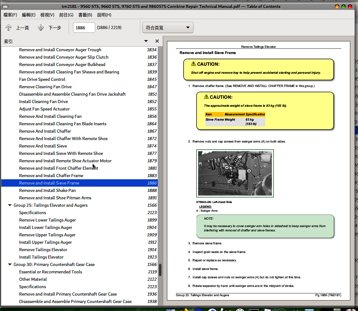
Remove and Install Sieve Frame
Remove and Install Shake Pan
Remove and Install Shoe Pitman Arms
Group 25: Tailings Elevator and Augers
Specifications
Remove Lower Tailings Auger
Install Lower Tailings Auger
Remove Upper Tailings Auger
Install Upper Tailings Auger
Remove Tailings Elevator
Install Tailings Elevator
Group 30: Primary Countershaft Gear Case
Essential or Recommended Tools
Other Material
Specifications
Remove and Install Primary Countershaft Gear Case
Disassemble and Assemble Primary Countershaft Gear Case
Group 35: Header Electromagnetic Clutch
Specifications
Remove Header Electromagnetic Clutch
Header Electromagnetic Clutch—Exploded View
Install Header Electromagnetic Clutch
Section 130: Grain Tank and Unloading System Repair
Group 05: Grain Tank Cross Augers
Remove Grain Tank Cross Augers (Regular Unload Rate)
Install Grain Tank Cross Augers (Regular Unload Rate)
Remove Grain Tank Cross Augers (High Unload Rate)
Install Grain Tank Cross Augers (High Unload Rate)
Group 10: Unloading Auger System Drives
Specifications
Remove and Install Unloading Auger Drive Belt
Remove and Install Unloading Auger Drive Countershaft—Style A
Remove and Install Unloading Auger Drive Countershaft—Style B
Group 15: Vertical Unloading Auger and Lower Gear Case
Essential or Recommended Tools
Specifications
Remove Vertical Auger Lower Gear Case and Vertical Auger
Disassemble and Assemble Vertical Auger Lower Gear Case
Install Vertical Auger and Vertical Auger Lower Gear Case
Group 20: Horizontal Unloading Auger and Gear Case
Essential or Recommended Tools
Other Material
Specifications
Inspection of Horizontal Unloading Auger
Horizontal Unloading Auger—Regular Unload Rate
Horizontal Unloading Auger—High Unload Rate
Remove and Install Unloading Auger Grain Saver Door
Remove Horizontal Auger
Install Horizontal Auger
Folding Horizontal Auger Housing—Exploded View
Folding Horizontal Auger—Exploded View
Folding Horizontal Auger Pivot—Exploded View
Remove and Install Folding Auger Actuator
Remove and Install Outer Folding Auger Assembly
Remove and Install Folding Auger Rings
Remove Rear Horizontal Folding Auger
Remove Front Horizontal Folding Auger
Remove Front Horizontal Folding Auger
Install Front Horizontal Folding Auger
Install Rear Horizontal Folding Auger
Remove Horizontal Auger Gear Case
Disassemble And Assemble Horizontal Unloading Auger Gear Case
Install Horizontal Auger Gear Case
Remove Horizontal Unloading Auger Tube
Install Horizontal Unloading Auger Tube
Unloading Auger Elbow—Exploded View
Remove Horizontal Auger Elbow
Install Horizontal Auger Elbow
Remove Unloading Auger Charge Housing
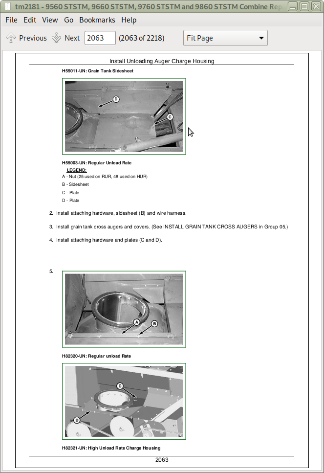
Install Unloading Auger Charge Housing
Group 25: Clean Grain Elevator
Other Material
Specifications
Adjust Clean Grain Elevator Chain
Remove Clean Grain Elevator
Install Clean Grain Elevator
Remove and Install Clean Grain Elevator Gear Case
Disassemble and Assemble Clean Grain Elevator Gear Case
Remove And Install Clean Grain Loading Auger
Replace Clean Grain Loading Auger Bearing
Remove And Install Lower Clean Grain Auger
Group 30: Grain Tank and Extensions
Grain Tank
Grain Tank Extensions
Section 140: Engine Gear Case and Control Valve Repair
Group 05: Engine Gear Case and Valve
Essential or Recommended Tools
Other Material
Specifications
General Information
Remove and Install Engine Gear Case
Engine Gear Case Specifications
Remove and Install STS Rotor Variable Drive
Disassemble and Assemble STS Rotor Variable Drive
Remove and Install STS Rotor Variable Drive Shaft
Remove and Install Transfer Gear Case
Disassemble and Assemble Transfer Gear Case
Disassemble and Assemble Separator Drive Wet Clutch
Disassemble and Assemble Hydrostatic Gear Set
Set Gear Position
Preload Bearings
Disassemble and Assemble Straw Chopper/Unloading System
Set Separator Gear Position
Preload Bearings
Disassemble and Assemble Separator Drive
Preload Separator Drive Bearings
Set Separator Drive Gear Backlash
Disassemble and Assemble Hydrostatic Pump Drive
Preload Hydrostatic Pump Drive Bearings
Set Hydrostatic Pump Drive Gear Backlash
Disassemble and Assemble Oil Screen
Disassemble and Assemble Oil Trough
Disassemble and Assemble Dipstick Tube
Remove and Install Filter
Remove and Install Pressure Regulating Valve
Disassemble and Assemble Pressure Regulating Valve
Section 199: Dealer Fabricated Tools
Group 05: Dealer Fabricated Tools
DFRW20—Compressor Holding Fixture
DFHXT1—Split Ring Tool
John Deere Combines 9560 STS, 9660 STS, 9760 STS, 9860 STS Repair Service Manual (TM2181)
![]()