
John Deere Combines 1470, 1570, W330 (South American Edition) Diagnosis and Tests Service Manual (TM801119)
Complete Diagnosis and Tests manual with electrical wiring diagrams for John Deere Combines Models 1470, 1570 and W330 (South American Edition), with workshop information to maintain, diagnose, and service like professional mechanics.
John Deere Combines Models 1470, 1570 and W330 (South American Edition) workshop Operation and Tests manual includes:
* Numbered table of contents easy to use so that you can find the information you need fast.
* Detailed sub-steps expand on repair procedure information
* Numbered instructions guide you through every repair procedure step by step.
* Troubleshooting and electrical service procedures are combined with detailed wiring diagrams for ease of use.
* Notes, cautions and warnings throughout each chapter pinpoint critical information.
* Bold figure number help you quickly match illustrations with instructions.
* Detailed illustrations, drawings and photos guide you through every procedure.
* Enlarged inset helps you identify and examine parts in detail.
TM801119 - John Deere Combines 1470, 1570, W330 (South American Edition) Technical Manual (Diagnosis and Tests).PDF
Total Pages: 1,812 pages
File Format: PDF (bookmarked, ToC, Searchable, Printable, high quality)
Language: English
MAIN SECTIONS
References in this manual
Safety
Safety Information
Diagnostics
Trouble Codes During Calibrations
INFO-TRAK Trouble Codes
CCU Trouble Codes
HCU Trouble Codes
Engine System
General Information
Test and Adjustment Procedures
Engine Diagnostics
Identification and Location of Components
Cooling and Air Intake Systems
General Information
Test and Adjustment Procedures
Air Intake System Diagnostic
Engine Cooling System Diagnostic
Identification and Location of Components
Electrical System
How To Use Diagnostic Information
Trouble Codes
Fuse Board
Starting the Engine
Engine Shut-Off-1470 (6.8 L)
Engine Shut-Off-1570 (8.1 L)
Recharging Battery
Engine Speed Sensor-1470 (6.8 L) and 1570 (8.1 L)
ECU - Power Feed-1570 (6.8 L)
ECU - Fuel System and Throttle-1570 (6.8 L)
ECU - Sensors-1570 (6.8 L)
ECU - Warning Light and Interface-1570 (6.8 L)
CCD Bus - Communication between Boards
CCU - Power Feed
CCU - Separator Engage
CCU - Separator Speed Adjustment
CCU - Header Engage
CCU - Unloading Auger Engage
CCU - Unloading Auger Engage
CCU - Reverser Engage
CCU - Chaff Spreader Speed Adjustment
CCU - Straw Chopper Engage
CCU - Straw Chopper Speed Sensor
CCU - Fan Speed Adjustment
CCU - Fan Speed Sensor
CCU - Concave Adjustment
CCU - Fuel Level
CCU - Engine Coolant Temperature
CCU - Engine Oil Pressure - 1470 (6.8 L) and 1570 (8.1 L)
CCU - Engine Oil Pressure - 1570 (6.8 L)
CCU - Parking Brake
CCU - Tailings Elevator Auger Speed Sensor
CCU - Straw Walker Crankshaft Speed Sensor
CCU - Clean Grain Elevator Auger Speed Sensor
CCU - Engine Air Filter Sensor - 1470 (6.8 L) and 1570 (8.1 L)
CCU - Engine Air Filter Sensor - 1570 (6.8 L)
CCU - Hydraulic Oil Temperature Sensor
CCU - Hydraulic Oil Level and Filter Sensor
CCU - Grain Tank Filling Level Sensor
CCU - Plugging Sensors
CCU - Reel speed
HCU - Power Feed
HCU - Automatic Cutting Height Control - Flex Header
HCU - Automatic Cutting Height Control - Rigid Header
HCU - Automatic Cutting Height Control - Corn Header
HCU - Manual Cutting Height Control
HCU - Cutting Platform Automatic Lateral Tilt Control
HCU - Corn Header Automatic Lateral Tilt Control
HCU - Header Manual Lateral Tilt Control
HCU - Manual Control of Reel Horizontal Position
HCU - Manual Control of Reel Vertical Position
HCU - Cutterbar Pressure Adjustment
HCU - Corn Header Deck Plates Adjustment
INFO-TRAKINFO-TRAK is a trademark of the Deere & Company Monitor/ Drive Shaft Speed Monitor
Harvest Performance Monitor
Hectaremeter
Windshield Washer
Windshield Wiper
Radio
A/C
Horn
Cigarette Lighter
Fuse Tester
Pneumatic Seat Compressor
Cab Interior Light
Cab Auxiliary Work Lights
Work Lights and Spot Lights On Mirror Arms
Headlights
Unloading Auger Lighting
Reverse Light and Backup Alarm
Engine and Sieves Lighting
Brake Lights
Switch Lighting
Turn Signal and Hazard Warning Lights
Indicators
Beacon Lights and Grain Tank Lighting
Four-Wheel Drive
AutoTrac Power Feed
HCU Test Procedures
CCU Test Procedures
Connectors
Drive Train
Specifications
Checking Parts for Wear
Hydrostatic System Test
Transmission
Four-Wheel Drive
Two-Speed Four-Wheel Drive
Brakes, Steering and Rear Axle
Brake System
Drum Brakes
Steering System
Hydraulic System
General Information
Identification of Type
Main and Secondary Control Block - A-Type
Unified Hydraulic Valve Block - B-Type
Steering
Reel and Reverser (Without Chaff Spreader)
Reel, Reverser and Chaff Spreader
Header Raise
Hydrostatic Drive
Location of Hydraulic Components
Cab
Cab and Operator`s Seat
Air Conditioning and Heating
Air Conditioning and Heating
Ventilation and Heating-Troubleshooting
Operational Tests and Troubleshooting
Air Conditioning System Operation
tm801119 - Colheitadeiras1470, 1570DiagnósticoEdição Sul Americana -: (South American Edition)
Table of Contents
References in this manual
Section 205: Safety
Group 05: Safety Information
Live With Safety
Work in Clean Area
Work In Ventilated Area
Wear Protective Clothing
Service Machines Safely
Prepare for Emergencies
Avoid High-Pressure Fluids
Service Accumulator Systems Safely
Park Machine Safely
Transporting the Combine Safely
Handle Fluids Safely—Avoid Fires
Prevent Battery Explosions
Prevent Acid Burns
Support Machine Properly
Remove Paint Before Welding or Heating
Avoid Heating Near Pressurized Fluid Lines
Illuminate Work Area Safely
Replace Safety Signs
Use Proper Lifting Equipment
Service Tires Safely
Practice Safe Maintenance
Use Proper Tools
Dispose of Waste Properly
Section 211: Diagnostics
Group 05: Trouble Codes During Calibrations
Code E02
Code E05
Code E06
Code E07
Code E09
Code E11
Code E12
Code E13
Code E14
Code E21
Code E22
Code E23
Code E24
Code E31
Code E32
Code E33
Code E34
Code E41
Code E42
Code E43
Code E44
Code E51
Code E52
Code E53
Code E54
Code E55
Code E56
Code E61
Code E62
Code E63
Code E64
Code E71
Code E72
Code E73
Code E74
Code E75
Code E76
Code E81
Code E82
Code E83
Code E84
Code E85
Code E86
Code E91
Code E92
Code E93
Code E94
Code E95
Code E96
Group 10: INFO-TRAK Trouble Codes
Code 72E
Code 101E
Code 102E
Code 122E
Code 123E
Code 128E
Code 130E
Code 131E
Code 132E
Code 135E
Code 136E
Code 137E
Group 20: CCU Trouble Codes
Code 105E
Code 106E
Code 107E
Code 108E
Code 109E
Code 110E
Code 111E
Code 112E
Code 150E
Code 151E
Code 152E
Code 153E
Code 154E
Code 155E
Code 156E
Code 157E
Code 158E
Code 159E
Code 160E
Code 161E
Code 162E
Code 163E
Code 164E
Code 166E
Code 167E
Code 168E
Code 169E
Code 170E
Code 171E
Code 172E
Code 173E
Code 174E
Code 175E
Code 176E
Code 177E
Code 178E
Code 179E
Code 180E
Code 181E
Code 182E
Code 186E
Code 187E
Code 188E
Code 189E
Code 190E
Code 191E
Code 192E
Code 193E
Code 194E
Code 195E
Code 196E
Code 197E
Code 198E
Code 199E
Code 217E
Group 25: HCU Trouble Codes
Code 211E
Code 212E
Code 213E
Code 214E
Code 215E
Code 216E
Code 218E
Code 220E
Code 221E
Code 222E
Code 224E
Code 225E
Code 226E
Code 227E
Code 228E
Code 232E
Code 233E
Code 234E
Code 235E
Code 236E
Code 240E
Code 241E
Code 242E
Code 243E
Code 244E
Code 245E
Code 246E
Code 247E
Code 248E
Section 220: Engine System
Group 05: General Information
How to Use this Section
Engine Diagnostic Specifications
Group 10: Test and Adjustment Procedures
Do Not Modify the Fuel System
Checking for Air in Fuel Return Line
Bleeding Fuel System—1470 (6.8 L)
Bleeding Fuel System—1570 (6.8 L)
Bleeding Fuel System—1570 (8.1 L)
Engine Oil Pressure Test 6.8 L
Engine Oil Pressure Test 8.1 L
Fuel Transfer Pump Pressure Test—1570 (6.8 L)
Fuel Transfer Pump Pressure Test—1570 (8.1 L)
Turbocharger Pressure Test
Group 15: Engine Diagnostics
About Theory of Operation
Electronic Control System Operation—1570 (6.8 L)
Fuel System Flow
Fuel System Diagram—1470 (6.8 L) and 1570 (8.1 L)
Fuel System Diagram—1570 (6.8 L)
Group 20: Identification and Location of Components
Fuel Transfer Pump—1470 (6.8 L)
Fuel Transfer Pump—1570 (6.8 L)
Fuel Transfer Pump—1570 (8.1 L)
Fuel Tank Drain
Final Fuel Filter—1470 (6.8 L)
Final Fuel Filter—1570 (6.8 L)
Final Fuel Filter—1570 (8.1 L)
Primary fuel filter—1470
Primary fuel filter—1570
Fuel Cooler—1570 (6.8 L)
Fuel Tank Breather
Fuel Level Sensor
Drain Plug of the Final Fuel Filter—1470 (6.8 L)
Drain Plug of the Final Fuel Filter—1570 (6.8 L)
Drain Plug of the Final Fuel Filter—1570 (8.1 L)
Turbocharger—1470 (6.8 L)
Turbocharger—1570 (6.8 L)
Turbocharger—1570 (8.1 L)
Overflow Valve—1470 (6.8 L)
Overflow Valve—1570 (6.8 L)
Overflow Valve—1570 (8.1 L)
Section 230: Cooling and Air Intake Systems
Group 05: General Information
How to Use this Section
Testing Precautions
Group 10: Test and Adjustment Procedures
Aftercooler Leak Test—1570 (6.8 L)
Aftercooler Test Tool Manufacturing Procedure—1570 (6.8 L)
Aftercooler Leak Test—1570 (6.8 L)
Testing Radiator Cap—1470 (6.8 L) and 1570 (8.1 L)
Testing Cooling System—1470 (6.8 L) and 1570 (8.1 L)
Testing Expansion Tank Cap—1570 (6.8 L)
Testing Cooling System—1570 (6.8 L)
Inspect Thermostat and Test Thermostat Operating Temperature
Radiator Inspection
Group 15: Air Intake System Diagnostic
Theory of Operation
Air Intake Diagram
Air Intake System Flow
Group 15A: Engine Cooling System Diagnostic
Theory of Operation
Rotary Screen
Vacuum Duct
Radiators
Engine Fan
Engine Coolant Flow
engine Cooling System Diagram—1470 (6.8 L) and 1570 (8.1 L)
Engine Cooling System Diagram—1570 (6.8 L)
Group 20: Identification and Location of Components
Aftercooler of Engine and Radiator—1570 (6.8 L)
Vacuum Duct
Engine Air Filter—1470 (6.8 L)
Engine Air Filter—1570 (6.8 L)
Engine Air Filter—1570 (8.1 L)
Rotary Screen
Engine Cooling Fan
Radiator and Air Conditioning Condenser—1470 (6.8 L) and 1570 (8.1 L)
Hydrostatic Oil Cooler, Air Conditioning Condenser and Fuel Cooler—1570 (6.8 L)
Hydrostatic Oil Cooler—1470 (6.8 L) and 1570 (8.1 L)
Recovery Tank—1470 (6.8 L) and 1570 (8.1 L)
Expansion Tank—1570 (6.8 L)
Dust Ejector Valve
Thermostat—1470 (6.8 L)
Thermostat—1570 (6.8 L)
Thermostat—1570 (8.1 L)
Section 240: Electrical System
Group 05: How To Use Diagnostic Information
How To Use Electrical Diagnostic Group
Visual Inspection of Electrical System
Handling of Basic Electrical Components/Precautions with Vehicles Equipped with Computer Controlled Systems
Wiring Harness/Electrical Connector Repair and Handling
Diagnosis of Intermittent Failures
Diagnostic Diagram and Information on Symbols in DiagramHow to use an Electrical Diagram
Electrical Diagram Symbols
Seven Steps Electrical Test Procedure
Know the System
Ask the Operator
Inspect the System
Operate the Machine (if possible)
List the Possible Causes
Come to a Conclusion
Test your Conclusion
Service Tools and EquipmentRecommended Tools
ESD - Eletrostatic Discharge
Factors Causing Static Electricity
Prevention
Equipment
Precautions while Working
Group 10: Trouble Codes
Cab Alarm Priorities
Trouble Codes While Calibrating
INFO-TRAK Trouble Codes
CCU Trouble Codes
HCU Trouble Codes
Group 15: Fuse Board
Theory of Operation
A50 - Fuse Board
Group 15A: Starting the Engine
Theory of Operation
Electrical Diagram
Group 15B: Engine Shut-Off—1470 (6.8 L)
Theory of Operation
Electrical Diagram
Group 15C: Engine Shut-Off—1570 (8.1 L)
Theory of Operation
Electrical Diagram
Group 15D: Recharging Battery
Theory of Operation
Electrical Diagram
Group 15E: Engine Speed Sensor—1470 (6.8 L) and 1570 (8.1 L)
Theory of Operation
Electrical Diagram
Group 15F: ECU - Power Feed—1570 (6.8 L)
Theory of Operation
Electrical Diagram
Group 15G: ECU - Fuel System and Throttle—1570 (6.8 L)
Theory of Operation
Electrical Diagram
Group 15H: ECU - Sensors—1570 (6.8 L)
Theory of Operation
Electrical Diagram
Group 15I: ECU - Warning Light and Interface—1570 (6.8 L)
Theory of Operation
Electrical Diagram
Display of Diagnostic Gauge Data Parameters (Murphy Gauge)
Diagnostic Indicator Active DTC View
Stored DTC View for Diagnostic Indicator
Clean DTC Stored in Diagnostic Indicator
Group 15J: CCD Bus - Communication between Boards
Theory of Operation
Electrical Diagram
Group 15K: CCU - Power Feed
Theory of Operation
Electrical Diagram
Group 15L: CCU - Separator Engage
Theory of Operation
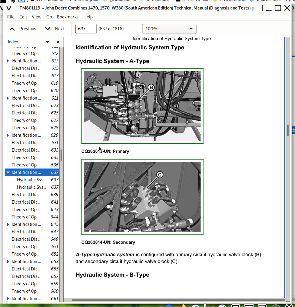
Identification of Hydraulic System Type
Electrical Diagram - A-Type
Electrical Diagram - B-Type
Group 15M: CCU - Separator Speed Adjustment
Theory of Operation
Identification of Hydraulic System Type
Electrical Diagram - A-Type
Electrical Diagram - B-Type
Group 15N: CCU - Header Engage
Theory of Operation
Identification of Hydraulic System Type
Electrical Diagram - A-Type
Electrical Diagram - B-Type
Group 15O: CCU - Unloading Auger Engage
Theory of Operation
Identification of Hydraulic System Type
Electrical Diagram - A-Type
Electrical Diagram - B-Type
Group 15P: CCU - Unloading Auger Engage
Theory of Operation
Identification of Hydraulic System Type
Electrical Diagram - A-Type
Electrical Diagram - B-Type
Group 15Q: CCU - Reverser Engage
Theory of Operation
Electrical Diagram
Group 15R: CCU - Chaff Spreader Speed Adjustment
Theory of Operation
Electrical Diagram
Group 15S: CCU - Straw Chopper Engage
Theory of Operation
Electrical Diagram
Group 15T: CCU - Straw Chopper Speed Sensor
Theory of Operation
Electrical Diagram
Group 15U: CCU - Fan Speed Adjustment
Theory of Operation
Electrical Diagram
Group 15V: CCU - Fan Speed Sensor
Theory of Operation
Electrical Diagram
Group 15W: CCU - Concave Adjustment
Theory of Operation
Electrical Diagram
Group 15X: CCU - Fuel Level
Theory of Operation
Electrical Diagram
Group 15Y: CCU - Engine Coolant Temperature
Theory of Operation
Electrical Diagram
Group 15Z: CCU - Engine Oil Pressure - 1470 (6.8 L) and 1570 (8.1 L)
Theory of Operation
Electrical Diagram
Group 15AA: CCU - Engine Oil Pressure - 1570 (6.8 L)
Theory of Operation
Electrical Diagram
Group 15AB: CCU - Parking Brake
Theory of Operation
Electrical Diagram
Group 15AC: CCU - Tailings Elevator Auger Speed Sensor
Theory of Operation
Electrical Diagram
Group 15AD: CCU - Straw Walker Crankshaft Speed Sensor
Theory of Operation
Electrical Diagram
Group 15AE: CCU - Clean Grain Elevator Auger Speed Sensor
Theory of Operation
Electrical Diagram
Group 15AF: CCU - Engine Air Filter Sensor - 1470 (6.8 L) and 1570 (8.1 L)
Theory of Operation
Electrical Diagram
Group 15AG: CCU - Engine Air Filter Sensor - 1570 (6.8 L)
Theory of Operation
Electrical Diagram
Group 15AH: CCU - Hydraulic Oil Temperature Sensor
Theory of Operation
Electrical Diagram
Group 15AI: CCU - Hydraulic Oil Level and Filter Sensor
Theory of Operation
Electrical Diagram
Group 15AJ: CCU - Grain Tank Filling Level Sensor
Theory of Operation
Electrical Diagram
Group 15AK: CCU - Plugging Sensors
Theory of Operation
Electrical Diagram
Group 15AL: CCU - Reel speed
Theory of Operation
Electrical Diagram
Group 15AM: HCU - Power Feed
Theory of Operation
Electrical Diagram
Group 15AN: HCU - Automatic Cutting Height Control - Flex Header
Theory of Operation
Electrical Diagram
Group 15AO: HCU - Automatic Cutting Height Control - Rigid Header
Theory of Operation
Electrical Diagram
Group 15AP: HCU - Automatic Cutting Height Control - Corn Header
Theory of Operation
Electrical Diagram
Group 15AQ: HCU - Manual Cutting Height Control
Theory of Operation
Electrical Diagram
Group 15AR: HCU - Cutting Platform Automatic Lateral Tilt Control
Theory of Operation
Identification of Hydraulic System Type
Electrical Diagram - A-Type
Electrical Diagram - B-Type
Group 15AS: HCU - Corn Header Automatic Lateral Tilt Control
Theory of Operation
Identification of Hydraulic System Type
Electrical Diagram - A-Type
Electrical Diagram - B-Type
Group 15AT: HCU - Header Manual Lateral Tilt Control
Theory of Operation
Identification of Hydraulic System Type
Electrical Diagram - A-Type
Electrical Diagram - B-Type
Group 15AU: HCU - Manual Control of Reel Horizontal Position
Theory of Operation
Identification of Hydraulic System Type
Electrical Diagram - A-Type
Electrical Diagram - B-Type
Group 15AV: HCU - Manual Control of Reel Vertical Position
Theory of Operation
Identification of Hydraulic System Type
Electrical Diagram - A-Type
Electrical Diagram - B-Type
Group 15AW: HCU - Cutterbar Pressure Adjustment
Theory of Operation
Identification of Hydraulic System Type
Electrical Diagram - A-Type
Electrical Diagram - B-Type
Group 15AX: HCU - Corn Header Deck Plates Adjustment
Theory of Operation
Identification of Hydraulic System Type
Electrical Diagram - A-Type
Electrical Diagram - B-Type
Group 15AY: INFO-TRAKINFO-TRAK is a trademark of the Deere & Company Monitor/ Drive Shaft Speed Monitor
Operational Information — INFO-TRAK INFO-TRAK is a trademark of Deere & Company Monitor
INFOTRAK™ Monitor
INFO-TRAK Monitor Functions
Setting and Displaying Time
Tire Rolling Radius Code
Input of Machine-Specific Data
INFO-TRAK INFO-TRAK is a trademark of the Deere & Company Monitor Service Information
Electrical Diagram
Group 15AZ: Harvest Performance Monitor
Theory of Operation
Electrical Diagram
Group 15BA: Hectaremeter
Theory of Operation
How to Reset a Password
Electrical Diagram
Group 15BB: Windshield Washer
Theory of Operation
Electrical Diagram
Group 15BC: Windshield Wiper
Theory of Operation
Electrical Diagram
Group 15BD: Radio
Theory of Operation
Electrical Diagram
Group 15BE: A/C
Identification of Type
Theory of Operation - A-Type
Electrical Diagram - A-Type
Theory of Operation - B-Type
Electrical Diagram - B-Type
Group 15BF: Horn
Theory of Operation
Electrical Diagram
Group 15BG: Cigarette Lighter
Theory of Operation
Electrical Diagram
Group 15BH: Fuse Tester
Fuse Tester
Electrical Diagram
Group 15BI: Pneumatic Seat Compressor
Theory of Operation
Electrical Diagram
Group 15BJ: Cab Interior Light
Theory of Operation
Electrical Diagram
Group 15BK: Cab Auxiliary Work Lights
Theory of Operation
Electrical Diagram
Group 15BL: Work Lights and Spot Lights On Mirror Arms
Theory of Operation
Electrical Diagram
Group 15BM: Headlights
Theory of Operation
Electrical Diagram
Group 15BN: Unloading Auger Lighting
Theory of Operation
Electrical Diagram
Group 15BO: Reverse Light and Backup Alarm
Theory of Operation
Electrical Diagram
Group 15BP: Engine and Sieves Lighting
Theory of Operation
Electrical Diagram
Group 15BQ: Brake Lights
Theory of Operation
Electrical Diagram
Group 15BR: Switch Lighting
Theory of Operation
Electrical Diagram
Group 15BS: Turn Signal and Hazard Warning Lights
Theory of Operation
Electrical Diagram
Group 15BT: Indicators
Theory of Operation
Electrical Diagram
Group 15BU: Beacon Lights and Grain Tank Lighting
Theory of Operation
Electrical Diagram
Group 15BV: Four-Wheel Drive
Theory of Operation
Electrical Diagram
Group 15BW: AutoTrac Power Feed
Theory of Operation
Electrical Diagram
Group 15BX: HCU Test Procedures
Functions of leveled Control Handle
Header Control System Troubleshooting Tips
“Limp Home” Feature
Header Test Procedures—HCU
Diagnostic Mode Access Procedures—INFO-TRAK Monitor™
No. 1 Test Procedure, HCU Error Codes
Test Procedure No. 2 , Intermittent Circuit Tests
Test Procedure No. 3, Battery Voltage to Logic Circuit
Test Procedure No. 4 , Voltage to Valves (Y12, Y18, and Y19)
Test Procedure No. 5 , Battery Voltage Feed to Valves (Y3, Y4, Y14, Y15, Y16, Y17 and Y38)
Test Procedure No. 6, Sensors Power Feed
Test Procedure No. 7, Header Raise/Lower Valves Duty-Cycle
Test Procedure No. 8, Reel Raise/Lower and Tilt Manual Control Switches
Test Procedure No. 9, Manual Flex Pressure Switch—600 Series Flex Header
Test Procedure No. 10, Height Control Setting Pot (R3)
Test Procedure No. 12, Header Raise/Lower Sensitivity Pot (R4)
Test procedure no. 13, Feeder House Angle Sensor Calibration
Test Procedure No. 14, Left-hand Tilt Sensor
Test Procedure No. 15, Right-Hand Tilt Sensor
Test Procedure No. 17, Cutterbar Pressure Sensor (R14)
Test Procedure No. 18, Reverse switch (S55)
Test Procedure No. 20, Deck Plates - Corn Head Calibration
Test procedure No. 21, Height Sensor
Test Procedure No. 22, Resume and Header Engage Switch Positions
Test Procedure No. 23, Tilt (S61) and Height (S32) Switches
Test Procedure No. 24, Hydraflex Select Valve or Reel Raise/Lower Select Valve
Test Procedure No. 25, Header Raise/Lower Speed Display
Test Procedure No. 26, Reel and Tilt Valve Control
Test Procedure No. 30, Calibration Mode
Calibrating Procedure
Header Calibration Procedure—Step by Step
Test Procedure Nº 32, Header Type
Test Procedure No. 33, Period of Time Raise Valve ON
Test Procedure No. 34, Cutting Height Setting Display
Test Procedure Nº. 35, Height System Deadband
Test Procedure Nº. 36, Tilt System Deadband
Test Procedure No. 37, Enable/Disable Header Raise in Reverse Mode
Group 15BY: CCU Test Procedures
CCU Test Procedures
Diagnostic Mode Access Procedures—INFO-TRAK Monitor™
Test Procedure No. 1, CCU Error Codes
Test Procedure No. 2, Intermittent Circuit Tests
Test Procedure No. 3, Threshing Transmission Pressure
Test Procedure No. 4, Header Transmission Pressure
Test Procedure No. 5, Unloading Auger Transmission Pressure
Test procedure No. 6, Hydraulic Oil Return Pressure Sensor
Test procedure No. 7, Engine Water Temperature Sensor
Test procedure No. 8, Hydraulic Oil Temperature Sensor
Test procedure no. 9, Air Conditioning Temperature Sensor
Test procedure no. 10, Air Conditioning Adjustment Pot
Test Procedure No. 11, Reel Speed Sensor
Test procedure No. 12 Reel Speed Setting Potentiometer
Test Procedure No. 13, Straw Chopper Speed Sensor
Test Procedure No. 14, Clean Grains Elevator Speed Sensor
Test Procedure No. 15, Tailings Elevator Speed Sensor
Test Procedure No. 16, Straw Walker Speed Sensor
Test Procedure No. 18, Fuel Level Transducer
Test Procedure No. 19, Atmospheric Pressure Transducer
Test Procedure No. 20, Diesel Oil Density Setting
Test Procedure No. 21, Fuel Quantity Setting
Test Procedure No. 22, Battery Voltage to Logic Circuit
Test Procedure No. 23, Voltage to Valves (Y21, Y22, Y26 and Y28)
Test Procedure No. 24, Voltage to Valves (Y1, Y2, Y5, Y20, Y23 and Y24)
Test Procedure No. 25, Sensors Power Feed
Test procedure no. 26, Machine Adjustments
Test procedure no. 27, Calibrating Unloading Auger Position
Test Procedure No. 28, Unloading Auger Opening Time Calibration
Test Procedure No. 29, Priority Selection for Reel Speed Control
Test Procedure No. 30 Panel Softkey Status
Test Procedure No. 31 Armrest Softkey Status
Test Procedure No. 32 Softkey and Switches Status
Test Procedure No. 33, Separator Belt, Header and Unloading Auger Adjustment Mode
Test Procedure No. 34, Valves Return Signal (Group 1)
Test Procedure No. 35, Valves Return Signal (Group 2)
Test Procedure No. 36, Valves Return Signal (Group 3)
Group 20: Connectors
How to Use Connector Data
Wire Colors and Code Numbers
A4 - Loss Monitor Board Connector
A4a - CCD Connector
A8 - Engine Control Unit Connector (ECU)
A10 - Engine Diagnostic Gauge (Murphy Gauge) Connector
A13 - CB Radio Connector
A18 - Area Counter Connector
B2 - Engine Oil Pressure Sensor Connector
B3 - Air Conditioning Temperature Sensor Connector
B4 - Coolant Temperature Sensor Connector
B5 - Reel Speed Sensor
B6 - Ground Speed Sensor Connector
B7 - Hydraulic Oil Filter Sensor Connector
B8 - Hydraulic Oil Temperature Sensor Connector
B9 - Reel Speed Control Switch Connector
B10 - Engine Air Filter Sensor Connector—1570 (6.8 L)
B10 - Engine Air Filter Sensor Connector
B11 - Fuel Tank Sensor Connector
B12 - Horn Connector
B13 - Air Conditioning Air Temperature Adjustment Potentiometer Connector - A-Type
B13 - Air Conditioning Air Temperature Adjustment Potentiometer Connector - B-Type
B14 - Low Pressure Switch Connector
B15 - High Pressure Switch Connector
B16 - Straw Chopper Impeller Speed Sensor Connector
B17 - Tailings Elevator Sensor Connector
B18 - Engine Oil Pressure Sensor Connector
B19 - Clean Grain Elevator Auger Speed Sensor Connector
B20 - Straw Walker Crankshaft Speed Sensor Connector
B21 - Left-hand Straw Walker Performance Sensor External Connector
B22 - Right-hand Straw Walker Performance Sensor External Connector
B23 - Cleaning Shoe Performance Sensor Connector
B26 - 3/4 Full Grain Tank Sensor Connector
B27 - Full Grain Tank Sensor Connector
B28 - Engine Speed Sensor Connector—1470 (6.8 L) and 1570 (8.1 L)
B28 - Engine Speed Sensor Connector—1570 (6.8 L)
B29 - Threshing Cylinder Speed Sensor Connector
B30 - Fan Speed Sensor Connector
B31 - Coolant Temperature Sensor Connector
B32 - Fuel Pressure Sensor Connector
B34 - Manifold Air Temperature Sensor Connector
B39 - Left-hand Speaker Connector
B39 - Right Height Sensor - Corn Head
B40 - Right-hand Speaker Connector
B40 - Central Height Sensor - Corn Head
B41 - Water-In Fuel Gauge Sensor Connector
B41 - Left Height Sensor - Corn Head
B43 - Rear Buzzer Connector
B47 - Deck plates position sensor - Corn head
B49 - Separator Pressure Sensor Connector
B50 - Grain Tank Unloading Pressure Sensor Connector
B51 - Header Transmission Pressure Sensor Connector
B54 - Fuel Temperature Sensor Connector
E1 - Left-hand Headlight Connector
E2 - Right-hand Headlight Connector
E4 - Right-hand Auxiliary Work Light Connector
E5 - Right-hand Auxiliary Work Light Connector
E6 - Left-hand Auxiliary Work Light Connector
E7 - Left-hand Auxiliary Work Light Connector
E8 - Unloading Auger Light Connector
E9 - Cigarette Lighter Socket Connector
E10 - Grain Tank Light Connector
E12 - Cab Interior Light Connector
E13 - Left-Hand Tail Light Connector
E14 - Right-Hand Tail Light Connector
E15 - Left-hand Front Indicator Light Connector
E16 - Right-hand Front Indicator Light Connector
E18 - Right-hand Work Lamp Connector
E19 - Left-hand Work Lamp Connector
E20 - Engine Light Connector
E21 - Chaffer Light Connector
E23 - Left Reverse Light Connector
E24 - Right Reverse Light Connector
E25 - Left-hand Outside Mirror Work Spot Lamp Connector
E26 - Right-hand Outside Mirror Work Spot Lamp Connector
F51 - 20 A Fuse
G2 - Alternator Connectors
H13 - Left-Hand Tail Light Connector
H14 - Left-Hand Tail Light Connector
H15 - Left-hand Front Turn Signal Connector
H16 - Right-hand Front Turn Signal Connector
H20 - Cab Interior Alarm Connector
H21 - Cab Intermittent Indicator Light Connector
H34 - Indicators Connector
H36 - Engine Compartment Intermittent Indicator Light Connector
H43 - Left-hand brake Connector
H44 - Right-hand brake Connector
J1 - CCU Connector
J2 - CCU Connector
J3 - CCU Connector
K1 - Starting engine Relay Connectors
K4 - Power Supply Relay
K5 - Air Heater Relay Connectors
K13 - Injection pump feed relay
K16 - Engine Air Filter Sensor Relay
M1 - Starter Motor Connectors
M3 - Windshield Wiper Motor Connector
M4 - Cab Fan Connector - A-Type
M4 - Cab Fan Connector - B-Type
M5 - Seat Compressor Engine Connector
M8 - Concave Adjustment engine Connector
M9 - Fan engine Connector
M11 - Windshield Washer Motor Connector
P1 - Coolant Temperature Gauge Connector
P2 - Fuel Gauge Connector
P5 - Straw Walker Performance Monitor Connector
P6 - INFO-TRAK INFO-TRAK is a trademark of the Deere & Company Monitor Connector
P7 - Cleaning Shoe Performance Monitor Connector
R1 - Air Conditioning Fan Resistor Connector
R2 - Engine Air Intake Heater Connector
R3 - Header Height Control Switch Connector
R4 - PWM Setting Pot Connector
R14 - Cutterbar Pressure Sensor Connector
R23 - Left-hand Tilt Sensor Connector
R24 - Right-hand Tilt Sensor Connector
R25 - Height Sensor Connector
R26 - Feeder House Position Sensor Connector
R31 - Concave Sensor Connector
S1 - Starter Key Connector
S2 - Road Safety Switch Connector
S5 - Parking Brake Switch Connector
S7 - Brake Light Switch Connector
S8 - Horn Switch Connector
S10 - Reel Speed Manual Adjustment Switch Connector
S11 - Hazard Light Switch Connector
S12 - Turn Signal Switch Connector
S13 - Clearance Lights/ Headlights Switch Connector
S14 - Grain Tank Lighting Switch Connector
S15 - Chaff Spreader Switch Connector
S16 - Straw Walker Plugging Sensor Connector
S17 - Straw Chopper Plugging Sensor Connector
S18 - Beacon Lights Switch Connector.
S19 - Cab Auxiliary Work Light Switch Connector
S20 - Windshield Wiper Switch Relay Connector
S21 - Windshield Washer Motor Switch Connector
S22 - Air Conditioning Fan Switch Connector - A-Type
S22 - Air Conditioning Fan Switch Connector - B-Type
S23 - Reverse Light Switch Connector
S24 - Feeder House Reverser Switch Connector
S25 - Air Conditioning Temperature Control Knob Connector - A-Type
S25 - Air Conditioning Temperature Control Knob Connector - B-Type
S31 - Road Safety Switch Connector
S32 - Automatic Cutting Control Enable Switch Connector
S33 - Separator Drive Switch Connector
S34 - Header Drive Switch Connector
S35 - Unloading Auger Drive Switch Connector
S36 - Concave Adjustment Switch Connector
S37 - Engine Compartment Spot Lamp Switch Connector
S39 - Unloading Auger Swing Switch Connector
S40 - Threshing Cylinder Speed Adjustment Switch Connector
S41 - Fan Speed Adjustment Switch
S42 - Parking Brake Engage Switch Connector
S44 - Throttle Switch Connector
S45 - Seat Switch
S46 - Four Wheel Drive Switch Connector
S48 - Work lights and spot lights on mirror arms switch connector
S49 - Full/Dipped Beam Switch Connector
S50 - Cutterbar Pressure Select Valve Switch Connector
S52 - Demoisturizer Switch Connector
S55 - Reverse Travel Switch Connector
S57 - Third Gear Switch Connector
S61 - Tilt Enable Switch Connector (Automatic)
S63 - Battery Switch Connector
S66 - Header Lateral Tilt /Reel Horizontal Position Commuting Switch Connector (Manual Mode)
S67 - Fan Motor Limiting Switch Connector
S69 - Straw Chopper Inclinable Cover Switch Connector
S70 - Cleaning Shoe Spot Lamp Switch Connector
S71 - Unloading Auger Spot Lamp Switch Connector
X0 - Main Cab Harness Ground
X2 - Radio Connector
X3 - Front Main Harness Ground
X4 - Electrical Box Harness Grounding
X6 - Relay Board Connector
X7 - Relay Board Connector
X8 - Relay Board Connector
X15 - Trailer Socket
X15 - Fuse Board Connector
X16 - Fuse Board Connector - A-Type
X16 - Fuse Board Connector - B-Type
X17 - Fuse Board Connector
X18 - Fuse Board Connector
X19 - Fuse Board Connector
X19 - Indicator Lights Panel Connector
X20 - Electrical Box Power Feed Connector
X20 - Indicator Lights Panel Connector
X21 - Auxiliary Relays Board Connector
X22 - Auxiliary Relays Board Connector
X23 - Connector (W11 and W13)
X24 - Auxiliary Relays Board Connector
X25 - Connector (W1 and W11)
X26 - Connector (W1 and W11)
X27 - Connector (W1 and W11)
X29 - Connector (W6 and W8)
X30 - Connector (W6 and W8)
X35 - Connector (W1 and W2)
X36 - Connector (W1 and W3)
X36 - Joystick Connector
X37 - Connector (W1 and W3)
X43 - Load Solenoid Connector
X44 - Connector (W1 and W6)
X45 - Connector (W6 and W11)
X46 - Connector (W1 and W13)
X49 - Connector (W1 and W5)
X51 - Main Valve Stack Connector
X52 - Secondary Valve Stack Connector
X53 - HCU Board Connector
X54 - Unified Valve Block Connector
X55 - HCU Board Connector
X63 — ATU Connector
X64 - Diagnostic Connector of Engine Control Unit
X65 - Connector (W13 and W16)
X66 - Connector (W1 and W4) - A-Type
X66 - Connector (W1 and W4) - B-Type
X72 - Connector (W9 and W11)
X73 - Connector (W6 and W10)
X74 - Connector (W6 and W29)
X74 - HYDRA-FLEX Bypass Valve Solenoid Connector
X75 - Connector - Cutterhead
X76 - Connector (W6 and W17)
X81 - Heating Valve Connector
X91 - Cab Auxiliary Work Light Connector
X92 - Beacon Light Connector
X117 - Fuse Board Connector
X118 - Fuse Board Connector
Y1 - Injection Pump Connector
Y2 - Reel Speed Setting Valve Connector
Y3 - Header Raise Solenoid Connector
Y4 - Header Lower Solenoid Connector
Y7 - Chaff Spreader Solenoid Connector
Y9 - Fuel Secondary Solenoid Connector—1470 (6.8 L)
Y9 - Fuel Pump Solenoid Connector—1570 (8.1 L)
Y26 - Reverser Valve Solenoid Connector
Y27 - Left-hand Four Wheel Drive Solenoid Connector
Y29 - Straw Chopper Engage Solenoid Connector
Y32 - Right-hand Four Wheel Drive Solenoid Connector
Y33 - Air Conditioning Compressor Clutch Connector
Y37 - Four Wheel Drive Solenoid Connector
Y39 - Fuel Transfer Pump Connector
Section 250: Drive Train
Group 05: Specifications
Hydrostatic Drive
Hydrostatic Drive Components
Group 10: Checking Parts for Wear
Inspection of Parts
Insufficient Lubrication
Contamination with Abrasive Substances
Cavitation
Excessive rotation
Shaft Seal Inspection
Inspection of Thrust Plate
Inspection of Fixed Swashplate
Inspection of Piston Shoe
Inspection of Piston Retainer
Inspection of Cylinder Block
Inspection of Bearing Plate
Inspection of Valve Plate
Inspection of Bearing and Race
Inspection of Servo Piston
Inspection of Drive Shaft
Group 15: Hydrostatic System Test
Specification
Special Tools
Recommended Special Tool
Hydrostatic Pump Pre-Charge Pressure
Retract Pressure Relief Valve
Extend Pressure Relief Valve
Pressure of Reservoir Backflow Limiter Valve
Group 20: Transmission
Three-Speed Transmission—Operation
Lubrication Of Three-Speed Transmission
Transmission Lube Pressure Check
Section 255: Four-Wheel Drive
Group 10: Two-Speed Four-Wheel Drive
Operational Theory
Section 260: Brakes, Steering and Rear Axle
Group 05: Brake System
Brake System
Brake Fluid Reservoir
Adjusting Foot Brakes
Parking Brake
Brake Master Cylinder
Pressure Equalizing Valve
Group 10: Drum Brakes
Drum Brakes
Group 15: Steering System
Hydraulic Schematic
Hydrostatic Unit
Operation Of the Metering Element Impeller
Manual Operation Of The Unit
Section 270: Hydraulic System
Group 05: General Information
Testing Precautions
Hydraulic Symbols
Precautions to be Taken Prior to Disassembling A Valve
Identification of Hydraulic System Type
Description of Hydraulic System - A-Type
Description of Hydraulic System - B-Type
Quadruple Hydraulic Pump
Pump Failures
Group 10: Identification of Type
Identification of Hydraulic System Type
Group 10A: Main and Secondary Control Block - A-Type
Theory of Operation
Hydraulic Schematic
Secondary Control Block
Charging Valve
Cutterbar pressure and reel raise/lower select valve
Reel Raise/Lower Valve
Reel Forward/Reverse Valve
Lateral Tilt Valve
Unloading auger Valve
Group 10B: Unified Hydraulic Valve Block - B-Type
Theory of Operation
Hydraulic Schematic
Unified Hydraulic Valve Block
Load Valve
Cutterbar Pressure Select and Reel Raise/Lower Valve
Reel Raise/Lower Valve
Reel Extend/Retract Valve
Lateral Tilt Valve
Unloading Auger Valve
Group 15: Steering
Theory of Operation
Hydraulic Schematic
Group 20: Reel and Reverser (Without Chaff Spreader)
Theory of Operation
Hydraulic Schematic
Reel and reverser valve diagnosis
Group 20A: Reel, Reverser and Chaff Spreader
Theory of Operation
Hydraulic Schematic
Reel and reverser valve diagnosis
Group 25: Header Raise
Theory of Operation
Hydraulic Schematic
Header Valve Diagnosis
Group 30: Hydrostatic Drive
Theory of Operation
Diagram - Without Four Wheel Drive
Diagram - With Four Wheel Drive
Group 35: Location of Hydraulic Components
A52 - Main Valve Stack
A53 - Secondary Valve stack
A54 - Unified Valve Block
B8 - Oil Temperature Sensor
B49 - Separator Pressure Sensor
B50 - Unloading Auger Pressure Sensor
B51 - Header Transmission Pressure Sensor
H1 - Pressure Accumulator
H2 - Header Raise Cylinder
H3 - Separator Drive Cylinder
H4 - Straw Chopper Drive Cylinder
H5 - Reel Raise/Lower Master Cylinder
H6 - Reel Raise/Lower Auxiliary Cylinder
H8 - Unloading Auger Swing Cylinder
H10 - Threshing Cylinder Speed Variator
H12 - Header Tilt Cylinder
H13 - HYDRA-FLEX HYDRA-FLEX is a trademark of Deere & Company Cutterbar Cylinder
H14 - HYDRA-FLEX HYDRA-FLEX is a trademark of Deere & Company Cutterbar Left Cylinder
H15 - Left Steering Cylinder
H16 - Right Steering Cylinder
H17 - Steering Servostat
H18 - Quadruple hydraulic pump
H19 - Return Filter
H20 - Divider block
H22 - Unloading Auger Drive cylinder
H23 - Reel, reverser and spreader valve
H24 - Reel Hydraulic Motor
H25 - Hydraulic/Hydrostatic System Oil Reservoir
H29 - Threshing Pressure Accumulator
H30 - Cutterbar Pressure Accumulator
H35 - Header Drive Cylinder
H37 - Reel Fore/Aft Master Cylinder
H38 - Reel Fore/Aft Auxiliary Cylinder
H39 - Hydraulic Reverser Motor
H40 - Select Valve
H41 - Header Hitch Valve
H52 - Chaff Spreader Hydraulic Engines
H57 - Flow Control Valve—Extend
H58 - Flow Control Valve—Retract
Section 290: Cab
Group 05: Cab and Operator's Seat
Cab
Cab Air Filter
Air Intake And Distribution
Operator's Seat And Passenger's Seat
Mechanical Adjustment of Seat Position
Mechanical Adjustment of Seat Position
Adapting Seat to Operator’s Weight
Air Comfort Seat
System Diagnosis of Mechanical Seat
Section 290A: Air Conditioning and Heating
Group 05: Air Conditioning and Heating
Compressor and Drive
Identification of Type
Air Conditioning and Heating Unit - A-Type
Air Conditioning and Heating Unit - B-Type
Air Conditioning Housing
Air Conditioning Housing (Left-Hand Side) - A-Type
Air Conditioning Housing (Left-Hand Side) - B-Type
Air Conditioning Housing (Right-Hand Side)
Air Conditioning Housing (Hose Connections)
Temperature Control Switch With Sensor - A-Type
Temperature Control Switch With Sensor - B-Type
Air Conditioning Housing in Open Position - A-Type
Air Conditioning Housing in Open Position - B-Type
Evaporator With Expansion Valve
Air Control Flap - A-Type Only
Cab Rear and Lateral Wall Connectors and Hoses
Heater Control Valve and Air Conditioning System Low Pressure Switch
Group 10: Ventilation and Heating—Troubleshooting
Ventilation and Heating
Group 15: Operational Tests and Troubleshooting
Test Sequence
Air Conditioning and Heating Operational Checks
Safety in the Workplace
Handling Refrigerant
In the event of an Emergency
Storage of Containers of Refrigerant
R134a Refrigerant
Special Tools
Specifications
Troubleshooting
Explanation Of Checks
Air Conditioning System Checks
Pressure Deviations
Group 20: Air Conditioning System Operation
Principle Of Heat Exchange
R134a Refrigerant
Layout Of Refrigerant Circuit
Description Of Refrigerant Circuit Function
Description Of Refrigerant Circuit Operation (Continued)
Compressor
Condenser
Filter-Drier
Expansion Valve
Temperature Adjustment Mechanism - A-Type
Temperature Adjustment Mechanism - B-Type
Evaporator
Temperature Control Switch - A-Type
Temperature Control Switch - B-Type
John Deere Combines 1470, 1570, W330 (South American Edition) Diagnosis and Tests Service Manual (TM801119)
![]()