
John Deere Combines 1470, 1570, W330 (South America, Europe, CIS) Repair Service Manual (TM801319)
Complete service repair manual for John Deere Combines Models 1470, 1570 and W330 (South America, Europe and CIS), with workshop information to maintain, repair, and service like professional mechanics.
John Deere Combines Models 1470, 1570 and W330 (South America, Europe and CIS) workshop service repair manual includes:
* Numbered table of contents easy to use so that you can find the information you need fast.
* Detailed sub-steps expand on repair procedure information
* Numbered instructions guide you through every repair procedure step by step.
* Notes, cautions and warnings throughout each chapter pinpoint critical information.
* Bold figure number help you quickly match illustrations with instructions.
* Detailed illustrations, drawings and photos guide you through every procedure.
* Enlarged inset helps you identify and examine parts in detail.
TM801319 - John Deere Combines 1470, 1570, W330 (South America, Europe, CIS) Technical Manual (Repair).PDF
Total Pages: 1,308 pages
File Format: PDF (bookmarked, ToC, Searchable, Printable, high quality)
Language: English
MAIN SECTIONS
Foreword
General Information
Safety
Specifications
Reconditioning and Adjusting
Fuels and Lubricants
Engine
Removing and Installing Engine
Fuel System, Air Intake and Cooling
Fuel System
Air Intake System
Cooling system
Electrical System
General Information
Battery
Alternator
Starter Motor
Main Electrical System
Operator Presence Switch
Power Train
Engine Power Take-Off
Transmission and Gear box
Final Drives - 1470 ( - 0090583) and 1570 ( - 0090276)
Final Drives - 1470 (0090584) and 1570 (0090277 - ) and W330
Hydrostatic Ground Speed Drive
Hydrostatic/Hydraulic System Oil
Hydrostatic Pump
Hydrostatic Pump Tensioning Cylinder
Removing Hydrostatic Drive Motor
Four-Wheel Drive Hydraulic Motor
Tires and Wheels
Oil Cooler
Steel Track
Brakes, Steering and Rear Axle
Service and Parking Brakes
Hydrostatic Steering Unit - A-Type
Hydrostatic Steering Unit - B-Type
Rear Axle
Removing and Repairing Steering Cylinder
Hydraulic System
Hydraulic Circuits
Hydraulic Oil Reservoir
Quadruple Hydraulic Pump
Identifying Hydraulic System Type
Hydraulic Valve Blocks - A-Type
Hydraulic Valve Blocks - B-Type
Hydraulic Cylinders
Accumulator
Hydraulic System Oil
Miscellaneous
Bearings and Shafts
Belts
Drive Chains
Front Axle
Compressed Air System
Operator`s Station, Cab and Air Conditioning
Cab
Repairing Air Conditioning System
Operator`s Cab Heating System
Gear Shift Mechanism
Feeder House
Removing and Installing Feeder House
Removal of Parts and Adjustments
Hydraulic Reverser
Multi-coupler
Threshing System, Separation and Cleaning
Separator Drive
Threshing Cylinder Speed Variator
Threshing Cylinder
Concave
Beater Cylinder
Threshing Cylinder Speed Reduction Gear
Straw walker
Cleaning Shoes
Variable Fan Speed Drive and Fan
Grain Transport and Unloading
Tailings Elevator
Clean Grain Elevator
Grain Tank Unloading System
Unloading Auger Hydraulic Cylinder
Straw Chopper, Straw Distributor and Chaff Spreader
Straw Chopper
Straw Distributor
Chaff Spreader
Special Tools
Dealer Fabricated Tools
Table of Contents
Foreword
Section 10: General Information
Group 05: Safety
Work In Ventilated Area
Work in Clean Area
Dispose of Waste Properly
Prepare for Emergencies
Handle Fluids Safely—Avoid Fires
Avoid High-Pressure Fluids
Use Proper Lifting Equipment
Illuminate Work Area Safely
Live With Safety
Service Machines Safely
Support Machine Properly
Remove Paint Before Welding or Heating
Park Machine Safely
Prevent Acid Burns
Use Proper Tools
Service Tires Safely
Replace Safety Signs
Prevent Battery Explosions
Avoid Heating Near Pressurized Fluid Lines
Wear Protective Clothing
Service Accumulator Systems Safely
Transport Combine Safely
Practice Safe Maintenance
Group 10: Specifications
Specifications - 1470 (Latin America)
Specifications - 1570 (Latin America)
Specifications - 1470/1570 (Europe) and W330
Operating Speeds
Power Separator (if equipped)
Four-Wheel Drive
Steel Track
Wheel Configurations
Combine Dimensions
Safety Note Regarding the Subsequent Installation of Electrical and Electronic Appliances and/or Components
Metric Bolt and Screw Torque Values
Unified Inch Bolt and Screw Torque Values
Flat Face Seal Fittings Assembly and Installation—All Pressure Applications
Metric Face Seal Fitting Torque Chart—Standard Pressure Applications
Metric Face Seal Fitting Torque Chart—High Pressure Applications
SAE Face Seal Fitting Torque Chart—Standard Pressure Applications
SAE Face Seal Fitting Torque Chart—High Pressure Applications
Four Bolt Flange Fittings Assembly and Installation—All Pressure Applications
SAE Four Bolt Flange Cap Screw Torque Values—Standard Pressure Applications
SAE Four Bolt Flange Cap Screw Torque Values—High Pressure Applications
External Hex Plug Torque Chart
Prevent Hydraulic System Contamination
Group 15: Reconditioning and Adjusting
Tune-Up and Adjustment
Group 20: Fuels and Lubricants
Handle Fuel Safely—Avoid Fires
Filling Fuel Tank
Diesel Fuel
Biodiesel Fuel
Heavy Duty Diesel Engine Coolant
Diesel Engine Break-In Oil
Diesel Engine Oil
Testing Diesel Fuel
Lubricity of Diesel Fuel
Gear Oil
Hydraulic System Oil
Grease
Lubricant Storage
Alternative and Synthetic Lubricants
Use Genuine John Deere Parts
Section 20: Engine
Group 05: Removing and Installing Engine
Special Tools
Preliminary Work
Engine Repair
Engine Installation
Section 30: Fuel System, Air Intake and Cooling
Group 05: Fuel System
Specification
Fuel Tank
Fuel Feeding System — Engines 6068TCQ18
Fuel Feeding System — Engines 6068HCQ06
Fuel Feeding System — Engines 6081AJ01
Fuel Feeding System — Engines 6068HCQ81 and 6068HCQ82
Fuel Tank Cap
Cleaning Primary Filter
Bleeding off Water from Primary Fuel Filter (Mechanical Transfer Pump)
Bleeding off Water from Primary Fuel Filter (Electrical Transfer Pump)
Replacing Fuel Filter — Engines 6068HCQ81 and 6068HCQ82
Replacing Fuel Filter — Engines 6068TCQ18 and 6068HCQ06
Replacing Fuel Filter - Engines 6081AJ01
Bleeding the Fuel System
Bleeding Fuel in Final Fuel Filter
Bleeding Fuel System at the Fuel Injection Nozzles
Removing and Installing Fuel Tank
Throttle Parts
Adjustment of Throttle Lever (Engines without ECU)
Group 10: Air Intake System
Cooling System, Exhaust and Air Intake — Engines 6068TCQ18
Cooling System, Exhaust and Air Intake — Engines 6068HCQ06, 6068HCQ81 and 6068HCQ82
Cooling System, Exhaust and Air Intake — Engines 6081AJ01
Removing Engine Air Filter— Engines 6068TCQ18
Removing Engine Air Filter— Engines 6068HCQ06, 6068HCQ81 and 6068HCQ82
Removing Engine Air Filter— Engines 6081AJ01
Cleaning and Inspecting Filter Insert
Mounting Engine Air Filter Components
Group 15: Cooling system
Engine Coolant
Filling Up Engine Cooling System
Radiator Coolant Level
Cooling System—Flushing Sequence
Changing Engine Coolant
Radiator Components — Engines 6068TCQ18 and 6081AJ01
Radiator Components — Engines 6068HCQ06, 6068HCQ81 and 6068HCQ82
Radiator Rotating Screen Components
Radiator Rotating Screen Components
Section 40: Electrical System
Group 05: General Information
Special Tools
Remove Connector Body from Blade Terminals
Electrical Connector Handling
Replace SURE-SEAL SURE-SEAL is a trademark of ITT Cannon Electric. Connectors
Install WEATHER PACK WEATHER PACK is a trademark of Packard Electric. Contact
Replace Small MATE-N-LOK MATE-N-LOK is a trademark of AMP Inc. Socket Connector
Replace CPC Blade Type Connectors
Group 10: Battery
Prevent Battery Explosions
Removing Battery
Battery Switch
Installing and Connecting the Battery
Using a Booster Battery
Group 15: Alternator
General Information
Removing the Alternator
Checking Tension of Alternator V-Belt Tensioner Spring and Belt Wear
Checking Tensioner Spring Tension
Replacing Fan/Alternator V-Belt
Group 20: Starter Motor
Starter Motor
Repairing the Starting Relay
Group 25: Main Electrical System
Electronic Boards
Removing Main Electrical Box
Accessing Header Control Board
Fuse Tester
Starter Motor Relay — Engines 6068TCQ18, 6081AJ01, 6068HCQ81 and 6068HCQ82
Starter Motor Relay— Engines 6068HCQ06
Fuse and Relay Board
Relay and Diode Board
Identification of Hydraulic System Type
Solenoid Valves (Electric Valves) on Main Hydraulic Valve Block - A-Type
Solenoid Valves (Electric Valves) on Secondary Hydraulic Valve Block - A-Type
Solenoid Valves (Electric Valves) on Unified Hydraulic Valve Block - B-Type
Group 30: Operator Presence Switch
Special Tools
Removing and Installing the Switch
Section 50: Power Train
Group 05: Engine Power Take-Off
Engine Output Shaft Components
Removing the Quadruple Pump Belt Tensioner
Removing Power Take-off Components
Installing Power Take-off Components
Group 10: Transmission and Gear box
Other Material
Specification
Transmission Oil
Draining Oil, Removal of Suction Screen
Removing Transmission
Removing and Repairing Shifter Yoke and Shifter Cam
Installing Shifter Yokes
Installing the Front Cover with Shifter Cam—Latin America
Installing the Front Cover with Shifter Cam—Europe
Removal and Installation of Transmission Lube Pump
Removing and Installing of Transmission Lubrication Pump
Removal of Back-Shaft
Removing Differential
Exploded View of the Pinion
Exploded View of Input Shaft
Removal of Differential Parts
Assembling Differential Parts
Assembling Differential
Ground Speed Sensor
Adjusting Bearing Play of Differential Set
Adjusting Bearing Play of Back-shaft
Installing the Transmission
Group 15A: Final Drives - 1470 ( - 0090583) and 1570 ( - 0090276)
Special Tools
Specifications
Specification
Adjusting Play of Final Drive Axle End Bearings
Changing Final Drive Oil
Group 15B: Final Drives - 1470 (0090584) and 1570 (0090277 - ) and W330
Special Tools
Specifications
Specification
Repairing Final Drive
Changing Final Drive Oil
Group 20: Hydrostatic Ground Speed Drive
Special Tools
Other Material
Specifications
Serial Number Plate
Group 25: Hydrostatic/Hydraulic System Oil
Draining the Hydraulic/Hydrostatic System Oil
Filling the Hydraulic/Hydrostatic System with Oil
Bleeding Hydrostatic System
Group 30: Hydrostatic Pump
Precautions when Removing Hydrostatic Pump
Hydrostatic Pump Removal
Removing Hydrostatic Pump Components
Assembling Hydrostatic Pump Parts
Repairing Control Valve
Assembly of Hydrostatic Pump Cover
Group 35: Hydrostatic Pump Tensioning Cylinder
Hydrostatic Pump Tensioning Cylinder
General View of Tensioning Cylinder
Group 40: Removing Hydrostatic Drive Motor
Removing and Installing the Hydrostatic Motor
Removing Hydrostatic Motor Components
Replacement of the Cylinder Block Spring
Installing Motor Components
Removing and Mounting Motor Valve Block (Manifold)
Repairing Hydrostatic Motor Valve Block
Group 45: Four-Wheel Drive Hydraulic Motor
Special Tools
Other Material
Specification
Cleaning the Rear Drive Hydrostatic System
Removal of the Four Wheel Drive Hydraulic Motor
Installation of the Four Wheel Drive Hydraulic Motor
Hydraulic System for Activating the Rear Wheel Drive Motors
Removal and Installation of Flow Control Valve
Flow Control Valve—Disassembly and Assembly
Removing and Assembling Steering Yoke
Motor Rings, Bushings and Seals - Disassembly and Replacement
Speed Selection Solenoid Valve - Removal and Assembly
Speed Selection Spool - Removal and Installation
Piston Block and Cam Track - Removal and Installation
Removal and Replacement of Distribution Valve Seals
Removal and Installation of the Axle Stub Bearing and Seals
Group 50: Tires and Wheels
Specification
Tire Classification
Removing and Installing the Tires
Installing Front Axle Extension
Installing Front Wheels
Installing Rear Wheels
Hub Bolts—Replacement
Tire Inflation Pressures
Group 55: Oil Cooler
Cleaning Oil Cooler
Repair
Group 60: Steel Track
Support Axle Maintenance
Checking Wear of Steel Track Components
Section 60: Brakes, Steering and Rear Axle
Group 05: Service and Parking Brakes
Other Material
Specifications
Brake Fluid Reservoir
Draining Brake Fluid
Removing Brake Master Cylinder
Repairing Brake Master Cylinder
Mounting Brake Master Cylinder
Adjustment of Brake Master Cylinder Yoke
Parking Brake Adjustment
Repairing Equalizing Valve
Removing Brake Drum
Removing Brake Shoes
Removing brake operating cylinder
Repairing Brakes
Repairing brake operating cylinder
Installing Brakes
Bleeding Brake System
Group 10: Hydrostatic Steering Unit - A-Type
Identification of Type
Special Tools
Steering Column - Components
Steering Column - Components (continued)
General View of Steering System
Hydrostatic Steering Unit Removal
Hydrostatic Steering Unit Parts
Repairing Hydrostatic Steering Unit
Repairing Splitter Valve and Liner Subassembly
Assembling Servostat
Group 11: Hydrostatic Steering Unit - B-Type
Identification of Type
Special Tools
Other Material
Specifications
Steering Column - Components
Hydrostatic Steering Unit Column Components (Continued)
General View of Steering System
Removing Hydrostatic Steering Unit
Hydrostatic Steering Unit Parts
Disassembling Hydrostatic Steering Unit
Repairing Hydrostatic Steering Unit
Assembling Hydrostatic Steering Unit
Hydrostatic Steering Unit Tests and Adjustments
Installing Hydrostatic Steering Unit
Bleeding Hydrostatic Steering System
Group 15: Rear Axle
Special Tools
Specifications
Rear Axle With Support
Shaft End, Wheel Hub and Steering Rod
Rear Axle - Removal and Installation
Support Points for Raising Combine
Removing Rear Wheel Hub Bearings
Repairing Bearings of Rear Wheel Hub
Installing Bearings of Rear Wheel Hub
Removing and Installing Rear Axle End
Rear Wheel Alignment
Rear Axle Height and Width Adjustment—Four-Wheel Drive Combines
Group 20: Removing and Repairing Steering Cylinder
Removing Hydraulic Steering Cylinder
Steering Hydraulic Cylinder
Remove Air from Steering Hydraulic Cylinders
Section 70: Hydraulic System
Group 05: Hydraulic Circuits
Avoid High-Pressure Fluids
Identification of Hydraulic System Type
Valve Block Hydraulic System General View - A-Type
Valve Block Hydraulic System General View - B-Type
General View of Steering System
General View of the Head Raise System
General View of the Reel, Reverser and Spreader System
General View of the Reel and Reverser System
Group 10: Hydraulic Oil Reservoir
Hydraulic/Hydrostatic Oil Reservoir
Repair
Group 15: Quadruple Hydraulic Pump
Specifications
Quadruple Hydraulic Pump
Hydraulic Pump Tension System
Quadruple Hydraulic Pump Cases
Quadruple Hydraulic Pump Marking
Removing Hydraulic Pump Components
Replacing Shaft Seal
Installing Gasket and Support
Assembling Hydraulic Pump
Group 20: Identifying Hydraulic System Type
Identification of Hydraulic System Type
Group 20A: Hydraulic Valve Blocks - A-Type
Special Tools
Testing Precautions
Hydraulic Valve Block Components
Disassembly and Assembly of the Main Command
Secondary Command Torques
Torques for the Reel, Reverser and Straw Spreader Block
Torque for the Reel and Reverser Block
Header Block Torques
Group 20B: Hydraulic Valve Blocks - B-Type
Special Tools
Testing Precautions
Unified Hydraulic Valve Block Components
Disassembling and Assembling Unified Hydraulic Valve Block
Torques for the Reel, Reverser and Straw Spreader Block
Torque for the Reel and Reverser Block
Header Block Torques
Group 25: Hydraulic Cylinders
Special Tools
Repairing Hydraulic Cylinders
Head Lift Cylinder
Feeder House Hydraulic Cylinder
Unloading Auger, Separator Transmission and Straw Chopper Transmission Drive Cylinder
Group 30: Accumulator
Specification
Header Float System Accumulator - General Information
Replacement of the Header Float System Accumulator
Group 35: Hydraulic System Oil
Changing Hydraulic Oil
Bleeding Hydraulic System
Bleeding the Reel Lift Cylinder System
Section 80: Miscellaneous
Group 05: Bearings and Shafts
Repairing Bearings with Locking Ring
Installing Bearings with Locking Ring—Steel Bearing
Mounting Bearings with Locking Ring—Cast Iron Bearing
Direction of Combine Shaft Rotation
Group 10: Belts
Care and Servicing of Belts
Cleaning Belts
Examples of Unusual Belt Wear
Defective Belts
Removing Straw Chopper Intermediate Transmission Drive Belt
Installing Straw Chopper Intermediate Transmission Drive Belt
Installing Unloading Auger Drive Belt
Removing Quadruple Hydraulic Pump Belt
Installing Quadruple Hydraulic Pump Belt
Quadruple Hydraulic Pump Belt Tensioning
Removing Beater/Threshing Cylinder Drive Belt
Installing Beater/Threshing Cylinder Drive Belt
Hydrostatic Pump Belt Removal
Hydrostatic Pump Belt Removal
Installing Hydrostatic Pump Belt
Removing Fan Variable Speed Drive Belt
Installing Fan Variable Speed Drive Belt
Group 15: Drive Chains
Drive Chains
Safety Cotter Pin
Drive Chains —Connecting Link
Group 20: Front Axle
Front Axle
Group 25: Compressed Air System
Air Compressor
Pressure Relief Valve
Section 90: Operator's Station, Cab and Air Conditioning
Group 05: Cab
Removing and Installing Cab Windshield
Group 10: Repairing Air Conditioning System
Special Tools
Other Material
Compressor Specifications
Specification
Safety Regulations
Handling the Refrigerant
In the Event of an Emergency
Safety Equipment
Storing the Refrigerant Containers
R134a Refrigerant
Welding and Soldering Regulations
Important
General Information
Air Conditioning and Heating System Components
Filling the Cylinder
Cleaning the Air Conditioning System
Evacuating the System
Adding Oil to Air Conditioning System
Charging Air Conditioning System
Leak Test
Compressor - Removal and Installation
Checking Compressor Oil Level
Removing Compressor Clutch Components
Checking Clearance Between Clutch Halves
Installing Compressor
Removing and Installing Condenser
Drier - Removal and Installation
Identification of Type
Removing and Installing the Evaporator and Expansion Valve
Temperature Control Switch With Sensor
Removing and Installing High/Low Pressure Switch
Group 20: Operator's Cab Heating System
Air Conditioning and Heating System Components
Removing and Installing Fan and Radiator
Removing and Installing Heater Control
Cab Main Filter - Removal and Installation
Recirculating Filter - Removal and Installation
Group 25: Gear Shift Mechanism
Adjusting the Gear Shift Mechanism
Gear Shift Mechanism—Exploded View Schematic
Section 110: Feeder House
Group 05: Removing and Installing Feeder House
Removing Hoses—Simple Coupling
Removing Hoses—Multi-coupler
Removal of Feeder House
Installing Feeder House
Group 10: Removal of Parts and Adjustments
Lower Drum Components (Feeder House without Longitudinal Adjustment)
Drive Belt Tensioning Device — Components
Transmission from the Beater to the Feeder House
Lower Drum Components (Feeder House with Longitudinal Adjustment)
Specifications
Upper Feeder House Shaft Components
Feeder House Slip Clutch Components
Feeder House Slip Clutch Adjustment
Header Transmission Chain
Feeder House Disassembly
Feeder House Assembly
Adjusting Floating Roller Height—300 Series Feeder House
Adjusting Floating Roller Height—600 Series Feeder House
Adjusting Feeder House Front Face Angle
Tension of Conveyor Chains — 300 Series Feeder House
Tension of Conveyor Chains — 600 Series Feeder House
Group 15: Hydraulic Reverser
Specification
Hydraulic Reverser — Exploded View
Adjusting Reverser Drive Cable
Hydraulic Reverser Motor - Removal
Hydraulic Reverser Motor - Disassembly
Hydraulic Reverser Motor Components - Repair
Hydraulic Reverser Motor - Assembly
Hydraulic Reverser Motor - Installation
Group 20: Multi-coupler
Special Tools
Other Material
Specification
Feeder House Multi-Coupler Check Valve Identification
Disassemble, Inspect and Assemble Feeder House Multi-Coupler
Section 120: Threshing System, Separation and Cleaning
Group 05: Separator Drive
Specification
Threshing Drive Unit Idler Pulley
Adjusting Threshing Unit Drive Belt Guide
Group 10: Threshing Cylinder Speed Variator
Special Tools
Other Material
Specifications
Exploded View of Lower Pulley of Threshing Cylinder Speed Variator
Preparations for Removing Lower Pulley of Threshing Cylinder Speed Variator
Removing Lower Pulley of Threshing Cylinder Speed Variator
Disassembling Lower Pulley of Threshing Cylinder Speed Variator
Repairing and Installing Lower Pulley of Threshing Cylinder Speed Variator
Installing Lower Pulley of Threshing Cylinder Speed Variator
Exploded View of Upper Pulley of Threshing Cylinder Speed Variator
Removing Upper Pulley of Threshing Cylinder Speed Variator
Repairing Upper Pulley of Threshing Cylinder Speed Variator
Installing Upper Pulley of Threshing Cylinder Speed Variator
Function Check of Threshing Cylinder Speed Variator
Group 15: Threshing Cylinder
Special Tools
Specifications
Removing Threshing Cylinder Drive Shaft
Installing Threshing Cylinder Drive Shaft
Removing Stone Trap
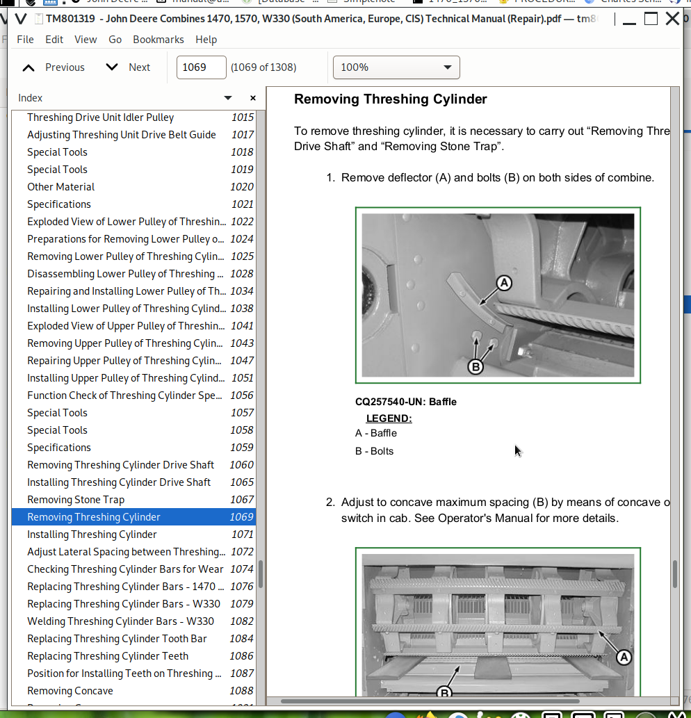
Removing Threshing Cylinder
Installing Threshing Cylinder
Adjust Lateral Spacing between Threshing Cylinder Teeth and Concave Teeth
Checking Threshing Cylinder Bars for Wear
Replacing Threshing Cylinder Bars - 1470 and 1570
Replacing Threshing Cylinder Bars - W330
Welding Threshing Cylinder Bars - W330
Replacing Threshing Cylinder Tooth Bar
Replacing Threshing Cylinder Teeth
Position for Installing Teeth on Threshing Cylinder
Group 20: Concave
Removing Concave
Replacing Concave Wires
Installing Concave
Removing Concave Tooth Bar
Concave Motor
Group 25: Beater Cylinder
Special Tools
Specifications
Removing Beater Cylinder
Installing Beater Cylinder
Group 30: Threshing Cylinder Speed Reduction Gear
Other Material
Exploded View of Threshing Cylinder Speed Reduction Gear
Removing Threshing Cylinder Speed Reduction Gear
Disassembling Reduction Gear and Lower Pulley
Repairing Threshing Cylinder Speed Reduction Gear
Assembling Components of Threshing Cylinder Speed Reduction Gear
Installing Threshing Cylinder Speed Reduction Gear
Group 35: Straw walker
Specification
Straw Walkers - Removal
Straw Walkers and Cleaning Shoes - Installation
Removing Straw Walker Crankshaft
Straw Walker Crankshaft - Installation and Adjustment
Straw Walker Drive Slip Clutch - Disassembly
Straw Walker Drive Slip Clutch - Installation and Adjustment
Chain Tension Adjustment
Group 40: Cleaning Shoes
Special Tools
Preparations for Removing Cleaning Shoes
Removing Front Arm
Removing the Rocker Arm and the Rear Arm
Removing Cleaning Shoes
Cleaning Shoes Drive Arm
Rocker Arm
Installing Bushings on Grain Pan Suspension—1470 and W330
Installing Bushings on Grain Pan Suspension—1570
Installing Bushings on Drive Shaft—1470 and W330
Installing Bushings on Drive Shaft—1570
Installing Bushings on Lower Cleaning Shoe Arm
Installing Cleaning Shoes
Group 45: Variable Fan Speed Drive and Fan
Removing Fan
Exploded View of Fan
Removing Fan Variable Speed Drive Toothed Wheel
Installing Fan Variable Speed Drive Toothed Wheel
Removing Fan Variable Speed Drive Bearings
Installing Fan Variable Speed Drive Bearings
Disassembling Lower Fan Variator Unit
Fan Variable Speed Drive - Repair
Fan Installation
Fan and Lower Unit Adjustments
Maximum Fan Speed Adjustment
Section 130: Grain Transport and Unloading
Group 05: Tailings Elevator
Specification
Lower Tailings Elevator Auger - Removal
Installing Lower Tailings Elevator Auger
Removing Tailings Elevator
Tailings Elevator Repair
Installing Tailings Elevator
Tailings Elevator Drive With Slip Clutch
Tailings Elevator Drive - Installation
Upper Tailings Auger - Removal
Upper Tailings Auger - Installation
Group 10: Clean Grain Elevator
Disassembling Clutch
Repairing and Mounting Clutch
Removing and Installing Clean Grain Auger
Leveling Auger Removal
Leveling Auger Installation
Clean Grain Elevator Upper Section - Removal
Disassemble and Installation of Clean Grain Elevator Upper Section
Removing Clean Grain Elevator Lower Section
Clean Grain Elevator Lower Section - Repair
Lower Clean Grain Elevator - Installation
Group 15: Grain Tank Unloading System
Grain Tank Unloading Tube - Removal
Repairing Unloading Auger Drive
Grain Tank Unloading Tube - Installing
Unloading Auger Drive Chain Tension
Unloading Tube Auger Drive - Exploded View
Unloading Tube — Exploded View
Unloading Tube — Exploded View (Continued)
Unloading Auger Transmission — Exploded View
Assembly
Grain Tank Paddle and Unloading Auger - Removal
Disassembly and Repair
Assembly
Grain Tank Unloading Auger - Exploded View
Paddle of Grain Tank Unloading Auger - Exploded View
Group 20: Unloading Auger Hydraulic Cylinder
Special Tools
Removing Auger Hydraulic Cylinder
Unloading Auger Hydraulic Cylinder
Section 140: Straw Chopper, Straw Distributor and Chaff Spreader
Group 05: Straw Chopper
Specification
Straw Chopper - General View
Straw Chopper Rotor - Exploded View
Straw Chopper
Straw Choppers—Removing Impeller
Rotor Knife Installation
Corn and Sunflower Straw Chopper
Removing Chopper Intermediate Assembly
Repairing the Chopper Intermediate Assembly
Removing Chopper Intermediate Assembly Shaft
Installation of Bearings and Shaft
Installing Intermediate Chopper Assembly
Group 10: Straw Distributor
Overview of the Electrical Engine for the Straw Distributor (If Equipped)
General Schematic of the Straw Distributor
Straw Distributor Setting
Adjustments of the Electrical Straw Distributor (If Equipped)
Group 15: Chaff Spreader
General Schematic of Chaff Spreader Layout
General Schematic of Chaff Spreader Pivot Arm;
Chaff Spreader - Operating and Transport Position
Chaff Spreader - Spread Angle Adjustment
Section 199: Special Tools
Group 05: Dealer Fabricated Tools
Support—DQ80702
Teflon Ring Installation Tool
Trunnion Installation Tool
Bushing Installation Tool—MD18159
Retainer Installation Tool—B00053
John Deere Combines 1470, 1570, W330 (South America, Europe, CIS) Repair Service Manual (TM801319)
![]()