
John Deere Track & Wheel Sugar Cane Harvester 3520, 3522 Diagnosis & Tests Service Manual (TM802619)
John Deere Track & Wheel Sugar Cane Harvester 3520, 3522 Diagnosis & Tests Service Manual (TM802619)
TM802619 - John Deere Track & Wheel Sugar Cane Harvester 3520, 3522 Technical Manual (Diagnosis & Tests).PDF
Complete Diagnosis & Tests manual with Electrical Wiring Diagrams for John Deere 3520, 3522 (SN. 0120701-), 3522 (SN. 0120021-) Track & Wheel Sugar Cane Harvester, with all the shop information to maintain, diagnose, repair, rebuild like professional mechanics.
John Deere Track & Wheel Sugar Cane Harvester 3520, 3522 workshop Operation & Test manual includes:
* Numbered table of contents easy to use so that you can find the information you need fast.
* Detailed sub-steps expand on repair procedure information
* Numbered instructions guide you through every repair procedure step by step.
* Troubleshooting and electrical service procedures are combined with detailed wiring diagrams for ease of use.
* Notes, cautions and warnings throughout each chapter pinpoint critical information.
* Bold figure number help you quickly match illustrations with instructions.
* Detailed illustrations, drawings and photos guide you through every procedure.
* Enlarged inset helps you identify and examine parts in detail.
Total Pages: 4,206 pages
File Format: PDF (bookmarked, ToC, Searchable, Printable, high quality)
Language: English
MAIN SECTIONS
Foreword
Manual Identification-READ THIS FIRST!
Sugar Cane Flow
General Information
How to Use This Manual
Safety Information
Identification
Machine Specifications
Hydraulic Specifications
Recommended Tools for Diagnostics
Accessing Diagnostic Trouble Codes and Diagnostic Addresses
Recall, Record and Clear Diagnostic Trouble Codes
Diagnostic Information for Electrical Components
Diagnostic Information for Hydraulic Components
Standard Electrical Symbols
Standard Hydraulic Symbols
Maintaining Hydraulic Systems and Components
Basic Diagnostics
Standard Torque Chart Procedures
Intermittent Diagnostic Trouble Code (DTC) Diagnostics
Diagnostic Trouble Codes
Cab Primary Display Control Unit
Engine Control Unit
Power Train Propulsion Control Unit
Propulsion Steering Control Unit
Vehicle Control Unit
Improved Height Control Unit (IHU)
Observable Symptoms and System Diagnostics
Observable Symptoms
Radio Does Not Operate Properly
Rear Feed Roller Shows Slow or No Operation
Recirculate Blower Motor Does Not Operate
Reverse Alarm Does Not Sound
Reversible Cooling Fan Does Not Reverse
Right Crop Divider Tilt Up Does Not Work
Right Crop Divider Tilt Down Does Not Work
Right Crop Divider Does Not Lift Correctly
Right Side Knives Show Slow or No Operation
Road Lights Does Not Operate Properly
Road Lights Does Not Operate Properly
Secondary Extractor Fan Does Not Operate
Secondary Hood Rotate Clockwise Does Not Operate
Secondary Hood Rotate Counterclockwise Does Not Operate
Side Knives Do Not Operate
Side Wipers Do Not Operate
Temperature Selector Does Not Operate Correctly
Throttle Selection Does Not Operate Properly
Topper Functions Do Not Operate
Topper Collectors Do Not Operate, But Serving Disk Does
Topper Lifts Does Not Operate
Varitorq Does Not Work
Windshield Washer Does Not Operate
Work Lights Does Not Operate Properly
Machine Moves Sluggish or Has No Movement
Engine
General Information
Calibrations or Operational and Preliminary Checks
Theory of Operation
Diagnostic Procedure
Fuel and Air Intake
General Information
Calibrations or Operational and Preliminary Checks
Theory of Operation
Schematic
Diagnostic Procedure
Electrical
General Information
Calibrations or Operational and Preliminary Checks
Theory of Operation
Schematic
Diagnostic Procedure
Control Units
General Reference
Calibrations or Operational and Preliminary Checks
Theory of Operation
Schematic
Diagnostic Procedure
Addresses for Cab Primary Display Control Unit
Addresses for Improved Height Control Unit
Addresses for Propulsion Steering Control Unit
Addresses for Power Train Propulsion Control Unit
Addresses for Vehicle Control Unit
Addresses for Virtual Terminal (in Cab)
Electrical Connector Information
General Information
X001-X099
X100-X199
X200-X299
X300-X399
X400-X499
X500-X599
Drive Train
Calibrations or Operational and Preliminary Checks
Theory of Operation
Schematic
Diagnostic Procedure
Steering and Brakes
General Information
Calibrations or Operational and Preliminary Checks
Service Brakes
Theory of Operation
Schematic
Diagnostic Procedure
Hydraulics
General Information
Calibrations or Operational and Preliminary Checks
Theory of Operation
Schematic
Diagnostic Procedure
Hydraulics Component Information
Accumulator
Cylinder, Actuator, or Piston
Check Valve
Filter
Valve Block, Assembly, or Gearcase
Cooler
Motor
Pump
Hydraulic Reservoir
Valve
Solenoid Valve
Operator Station
General
Air Suspension Seat and Armrest
Disassemble and Assemble
Schematic
Air Conditioning and Heating
Calibrations or Operational and Preliminary Checks
Theory of Operation
Schematic
Diagnostic Procedure
Special Tools
Special Tools and Part Numbers
tm802619 - 3520 3522 Sugar Cane Harvester Diagnosis and Tests Track and Wheel Machines
Table of Contents
Foreword
Manual Identification—READ THIS FIRST!
Sugar Cane Flow
Section 210: General Information
Group 05A: How to Use This Manual
Information Available in Sections, Groups and Subgroups
Group 05B: Safety Information
Recognize Safety Information
Understand Signal Words
Follow Safety Instructions
Operation Safety
Service Precautions
Safety when Cleaning or Storing
Seat Safety Shut-Off
Prevent Machine Runaway
Handle Fluids Safely—Avoid Fires
Prevent Battery Explosions
Prepare for Emergencies
Battery Safety
Jumping the Battery
Precautions for Alternators
Handling Batteries Safely
Charging the Batteries
Avoid High-Pressure Fluids
Escaping High Pressure Fluid Can Cause Serious Injury
Park Machine Safely
Avoid Power Lines
Support Machine Properly
Wear Protective Clothing
Work in Clean Area
Service Machines Safely
Work In Ventilated Area
Illuminate Work Area Safely
Replace Safety Signs
Use Proper Lifting Equipment
Use Handles and Steps
Use Cylinder Safety Stops
Remove Paint Before Welding or Heating
Avoid Heating Near Pressurized Fluid Lines
Avoid Explosive Release of Pressurized Coolants
Service Accumulator Safely
Service Tires Safely
Practice Safe Maintenance
Use Proper Tools
Dispose of Waste Properly
Live With Safety
Operate Safely
Avoid Tip-Overs
Keep Riders Off Machine
Stored Fuel Can Be Dangerous
Handle Fuel Safely—Avoid Fires
Avoid Fires
Handle Starting Fluid Safely
Handle Chemical Products Safely
Avoid Contact with Moving Parts
Keep Hands Away from Knives
Tilt Cab
Avoid Backover Accidents
Transport Machine Safely
Use Safety Lights and Devices
Group 05C: Identification
Identification Numbers
Machine Serial Number
Engine Serial Number
Interpreting the Serial Number of Your Machine 13 digits PIN
Interpreting the Serial Number of Your Machine 17 digits PIN
Group 05D: Machine Specifications
Machine Specifications
Group 05E: Hydraulic Specifications
Hydraulic Specifications
Group 05F: Recommended Tools for Diagnostics
Recommended Tools
Group 05G: Accessing Diagnostic Trouble Codes and Diagnostic Addresses
Accessing Diagnostic Trouble Codes and Addresses
Quick Procedure - Access Diagnostic Trouble Codes
Quick Procedure - Access Diagnostic Addresses
Group 05H: Recall, Record and Clear Diagnostic Trouble Codes
Recall, Record, and Clear Diagnostic Trouble Codes
Group 05I: Diagnostic Information for Electrical Components
Electrical Designators
Visually Inspect Electrical System
Wire Harness Test
Alternator Test
Group 05J: Diagnostic Information for Hydraulic Components
Hydraulic Designators
Troubleshooting Tips
Visually Inspect Hydraulic System
Group 05K: Standard Electrical Symbols
Electrical Symbols
Group 05L: Standard Hydraulic Symbols
Standard Hydraulic Symbols
Group 05M: Maintaining Hydraulic Systems and Components
Aeration and Cavitation
Hydraulic Components
Oil Storage and Filling
Oil Filtration
Group 05N: Basic Diagnostics
Seven Basic Steps
Troubleshooting Unresolved Problems
Group 05O: Standard Torque Chart Procedures
Unified Inch Bolt and Screw Torque Values
Metric Bolt and Screw Torque Values
Group 05: Intermittent Diagnostic Trouble Code (DTC) Diagnostics
Intermittent Diagnostic Trouble Code (DTC) Diagnostics
Section 211: Diagnostic Trouble Codes
Group 10A: Cab Primary Display Control Unit
PDU 000628.02 - Program Memory Fault
PDU 000628.12 - Program Memory Fault
PDU 000629.12 - PDU Control Unit Fault
PDU 000639.12 - PDU CAN Error Limit Exceeded
PDU 000639.14 - PDU CAN Error Limit Exceeded
PDU 002000.09 - ECU Message Missing
PDU 002003.09 - PTI or PTP Message Missing
PDU 002019.09 - SSU Message Missing
PDU 002038.09 - SDU Message Missing
PDU 002039.09 - Source Address 039 Message Missing
Group 10B: Engine Control Unit
ECU 000091.09 - CAN Throttle Message Error
ECU 000094.03 - Lo Pressure Fuel Pressure Signal Out of Range HI
ECU 000094.04 - Lo Pressure Fuel Signal Out of Range Lo
ECU 000094.17 - Lo Pressure Fuel Signal Slightly Lo
ECU 000097.03 - Water-in-Fuel Signal Out of Range HI
ECU 000097.04 - Water-in-Fuel Signal Out of Range Lo
ECU 000097.16 - Water-in-Fuel Detected
ECU 000100.01 - Engine Oil Pressure Signal Extremely Lo
ECU 000100.04 - Engine Oil Pressure Signal Out of Range Lo
ECU 000100.18 - Engine Oil Pressure Signal Moderately Lo
ECU 000100.31 - Oil Pressure is not Zero with Engine Stopped
ECU 000102.02 - Intake Manifold Pressure Signal Invalid
ECU 000102.03 - Intake Manifold Pressure Signal Out of Range HI
ECU 000102.04 - Intake Manifold Pressure Signal Out of Range Lo
ECU 000103.00 - Turbo Speed Signal Extremely HI
ECU 000103.05 - Turbo Speed Sensor Circuit has HI Resistance
ECU 000103.08 - Turbo Speed Signal Incorrect
ECU 000103.31 - Turbo Speed Signal Missing
ECU 000105.00 - Intake Manifold Air Temperature Signal Extremely HI
ECU 000105.03 - Intake Manifold Air Temperature Signal Out of Range HI
ECU 000105.04 - Intake Manifold Air Temperature Signal Out of Range Lo
ECU 000105.15 - Intake Manifold Air Temperature Signal Slightly HI
ECU 000105.16 - Intake Manifold Air Temperature Signal Moderately HI
ECU 000107.00 - Air Filter Pressure Differential Extremely HI
ECU 000108.02 - Barometric Pressure Signal Invalid
ECU 000110.00 - Engine Coolant Temperature Signal Extremely HI
ECU 000110.03 - Engine Coolant Temperature Signal Out of Range HI
ECU 000110.04 - Engine Coolant Temperature Signal Out of Range Lo
ECU 000110.15 - Engine Coolant Temperature Signal Slightly HI
ECU 000110.16 - Engine Coolant Temperature Signal Moderately HI
ECU 000110.17 - Engine Coolant Temperature Signal Slightly Lo
ECU 000157.03 - Fuel Rail Pressure Signal Out of Range HI
ECU 000157.04 - Fuel Rail Pressure Signal Out of Range Lo
ECU 000157.10 - Fuel Rail Pressure Rate of Change Abnormal
ECU 000157.17 - Fuel Rail Pressure Not Developed
ECU 000158.17 - ECU Power Down Error
ECU 000174.00 - Fuel Temperature Signal Extremely HI
ECU 000174.03 - Fuel Temperature Signal Out of Range HI
ECU 000174.04 - Fuel Temperature Signal Out of Range Lo
ECU 000174.16 - Fuel Temperature Signal Moderately HI
ECU 000189.00 - Engine Speed Derate Condition
ECU 000189.09 - Engine Speed Derate Condition
ECU 000190.00 - Engine Speed Extremely HI
ECU 000412.00 - EGR Temperature Signal Extremely HI
ECU 000412.03 - EGR Temperature Signal Out of Range HI
ECU 000412.04 - EGR Temperature Signal Out of Range Lo
ECU 000412.15 - EGR Temperature Signal Slightly HI
ECU 000412.16 - EGR Temperature Signal Moderately HI
ECU 000441.03 - Gear Oil Temperature Signal Out of Range HI
ECU 000441.04 - Gear Oil Temperature Signal Out of Range Lo
ECU 000611.03 - Injector Shorted
ECU 000611.04 - Injector Shorted
ECU 000627.01 - All Electronic Injector Circuits Have HI Resistance
ECU 000627.18 - Injector Power Supply Voltage Moderately Low
ECU 000629.12 - ECU EEPROM
ECU 000629.13 - ECU Boot Block
ECU 000636.02 - Camshaft Sensor Signal Error
ECU 000636.05 - Camshaft Sensor Circuit Has HI Resistance
ECU 000636.06 - Camshaft Sensor Circuit Has Lo Resistance
ECU 000636.08 - Camshaft Sensor Signal
ECU 000636.10 - Camshaft Signal Rate Change Abnormal
ECU 000637.02 - Crankshaft Position Sensor Signal
ECU 000637.05 - Crankshaft Position Sensor Circuit Has HI Resistance
ECU 000637.06 - Crankshaft Position Sensor Circuit Has Lo Resistance
ECU 000637.07 - Crankshaft Position and Position Signal
ECU 000637.08 - Crankshaft Position Timing Sensor Signal
ECU 000637.10 - Crankshaft Position Signal Rate Change Abnormal
ECU 000640.11 - External Engine Protection
ECU 000640.12 - External Engine Protection
ECU 000640.31 - External Derate
ECU 000641.04 - VGT Actuator Supply Voltage Out of Range Lo
ECU 000641.12 - VGT Actuator Communication
ECU 000641.13 - VGT Actuator Learn
ECU 000641.16 - Turbo Actuator Temperature Moderately HI
ECU 000651.02 - Injector 1 Part # Data Invalid
ECU 000651.05 - Injector 1 Circuit Has HI Resistance
ECU 000651.06 - Injector 1 Circuit Has Lo Resistance
ECU 000651.07 - Injector 1 Not Responding
ECU 000651.13 - Injector 1 Calibration Fault
ECU 000652.02 - Injector 2 Part # Data Invalid
ECU 000652.05 - Injector 2 Circuit Has HI Resistance
ECU 000652.06 - Injector 2 Circuit Has Lo Resistance
ECU 000652.07 - Injector 2 Not Responding
ECU 000652.13 - Injector 2 Calibration Fault
ECU 000653.02 - Injector 3 Part # Data Invalid
ECU 000653.05 - Injector 3 Circuit Has HI Resistance
ECU 000653.06 - Injector 3 Circuit Has Lo Resistance
ECU 000653.07 - Injector 3 Not Responding
ECU 000653.13 - Injector 3 Calibration Fault
ECU 000654.02 - Injector 4 Part # Data Invalid
ECU 000654.05 - Injector 4 Circuit Has HI Resistance
ECU 000654.06 - Injector 4 Circuit Has Lo Resistance
ECU 000654.07 - Injector 4 Not Responding
ECU 000654.13 - Injector 4 Calibration Fault
ECU 000655.02 - Injector 5 Part # Data Invalid
ECU 000655.05 - Injector 5 Circuit Has HI Resistance
ECU 000655.06 - Injector 5 Circuit Has Lo Resistance
ECU 000655.07 - Injector 5 Not Responding
ECU 000655.13 - Injector 5 Calibration Fault
ECU 000656.02 - Injector 6 Part # Data Invalid
ECU 000656.05 - Injector 6 Circuit Has HI Resistance
ECU 000656.06 - Injector 6 Circuit Has Lo Resistance
ECU 000656.07 - Injector 6 Not Responding
ECU 000656.13 - Injector 6 Calibration Fault
ECU 000970.09 - External Shutdown
ECU 000970.31 - External Shutdown Switch Activated
ECU 001075.12 - Lo Pressure Fuel Pump Status
ECU 001136.00 - ECU Temperature Signal Extremely HI
ECU 001136.16 - ECU Temperature Signal Moderately HI
ECU 001172.03 - Compressor Inlet Temperature Signal Out of Range HI
ECU 001172.04 - Compressor Inlet Temperature Signal Out of Range Lo
ECU 001180.00 - Turbine Inlet Temperature Signal Extremely HI
ECU 001180.16 - Turbine Inlet Temperature Signal Moderately HI
ECU 001347.03 - HI Pressure Fuel Pump Control Valve Signal Out of Range HI
ECU 001347.05 - HI Pressure Fuel Pump Solenoid Circuit Has HI Resistance
ECU 001347.07 - HI Pressure Fuel Pump Not Able to Meet Required Rail Pressure
ECU 001569.31 - Engine Power Derate Condition
ECU 002039.09 - Abnormal Update Rate
ECU 002039.14 - Engine Derate
ECU 002630.00 - Charge Air Cooler Outlet Temperature Signal Extremely HI
ECU 002630.03 - Charge Air Cooler Outlet Temperature Signal Out of Range HI
ECU 002630.04 - Charge Air Cooler Outlet Temperature Signal Out of Range Lo
ECU 002630.15 - Charge Air Cooler Outlet Temperature Signal Slightly HI
ECU 002630.16 - Charge Air Cooler Outlet Temperature Signal Moderately HI
ECU 002659.02 - EGR Mass FLo Rate Data
ECU 002659.15 - EGR Mass FLo Rate Data Slightly HI
ECU 002659.17 - EGR Mass FLo Rate Data Slightly Lo
ECU 002790.16 - Calculated Compressor Outlet Temperature Moderately HI
ECU 002791.02 - EGR Valve Position Signal
ECU 002791.07 - EGR Valve Not Reaching Expected Position Error
ECU 002791.13 - EGR Valve Calibration Error
ECU 002791.31 - EGR Valve Calibration Change
ECU 002795.07 - VGT Actuator Not Reaching Expected Position
ECU 003509.03 - Sensor Supply 1 Voltage Out of Range HI
ECU 003509.04 - Sensor Supply 1 Voltage Out of Range Lo
ECU 003510.03 - Sensor Supply 2 Voltage Out of Range HI
ECU 003510.04 - Sensor Supply 2 Voltage Out of Range Lo
ECU 003511.03 - Sensor Supply 3 Voltage Out of Range HI
ECU 003511.04 - Sensor Supply 3 Voltage Out of Range Lo
ECU 003512.03 - Sensor Supply 4 Voltage Out of Range HI
ECU 003512.04 - Sensor Supply 4 Voltage Out of Range Lo
ECU 003513.03 - Sensor Supply 5 Voltage Out of Range HI
ECU 003513.04 - Sensor Supply 5 Voltage Out of Range Lo
ECU 523379.03 - Single Point Ground #7 Fault
ECU 523744.31 - A/C Compressor is ON When it Should be Off
Group 10C: Power Train Propulsion Control Unit
PTP 000070.02 - Parking Brake Switch Fault
PTP 000070.14 - Parking Brake Switch
PTP 000168.03 - Battery voltage out of range high
PTP 000168.04 - Battery voltage out of range low
PTP 000237.31 - Vehicle identification number
PTP 000628.02 - Program memory
PTP 000628.12 - Program memory
PTP 000629.12 - Controller Malfunction
PTP 001504.14 - Operator out of seat during AutoTrac
PTP 001638.09 - Hydraulic temperature
PTP 002000.09 - Engine Speed Message Missing
PTP 003509.03 - Sensor Supply Voltage 1
PTP 003509.04 - Sensor Supply Voltage 1
PTP 003510.03 - Sensor Supply Voltage 2
PTP 003510.04 - Sensor Supply Voltage 2
PTP 003511.03 - Sensor Supply Voltage 3
PTP 003511.04 - Sensor Supply Voltage 3
PTP 003512.03 - Sensor Supply Voltage 4
PTP 003512.04 - Sensor Supply Voltage 4
PTP 003600.00 - Steering Straight Ahead Position Reset
PTP 003600.01 - Steering Straight Ahead Position Reset
PTP 003600.03 - Steering Straight Ahead Position Reset
PTP 003600.04 - Steering Straight Ahead Position Reset
PTP 003600.13 - Steering Straight Ahead Position Reset
PTP 003648.13 - Transmission neutral selector
PTP 520296.05 - Right Drive Auxiliary Pump Driver State - Forward
PTP 520296.06 - Right Drive Auxiliary Pump Driver State - Forward
PTP 520297.05 - Right Drive Auxiliary Pump Driver State - Reverse
PTP 520297.06 - Right Drive Auxiliary Pump Driver State - Reverse
PTP 520298.05 - Left Drive Auxiliary Pump Driver State - Forward
PTP 520298.06 - Left Drive Auxiliary Pump Driver State - Forward
PTP 520299.05 - Left Drive Auxiliary Pump Driver State - Reverse
PTP 520299.06 - Left Drive Auxiliary Pump Driver State - Reverse
PTP 520378.00 - Right Drive Pump Driver State - Reverse
PTP 520378.01 - Right Drive Pump Driver State - Reverse
PTP 520378.05 - Right Drive Pump Driver State - Reverse
PTP 520378.06 - Right Drive Pump Driver State - Reverse
PTP 520378.31 - Right Drive Pump Driver State - Reverse
PTP 520379.00 - Right Drive Pump Driver State - Forward
PTP 520379.01 - Right Drive Pump Driver State - Forward
PTP 520379.05 - Right Drive Pump Driver State - Forward
PTP 520379.06 - Right Drive Pump Driver State - Forward
PTP 520379.16 - Right Drive Pump Driver State - Forward
PTP 520379.31 - Right Drive Pump Driver State - Forward
PTP 520380.00 - Left Drive Pump Driver State - Forward
PTP 520380.01 - Left Drive Pump Driver State - Forward
PTP 520380.05 - Left Drive Pump Driver State - Forward
PTP 520380.06 - Left Drive Pump Driver State - Forward
PTP 520380.16 - Left Drive Pump Driver State - Forward
PTP 520380.31 - Left Drive Pump Driver State - Forward
PTP 520381.00 - Left Drive Pump Driver State - Reverse
PTP 520381.01 - Left Drive Pump Driver State - Reverse
PTP 520381.05 - Left Drive Pump Driver State - Reverse
PTP 520381.06 - Left Drive Pump Driver State - Reverse
PTP 520381.31 - Left Drive Pump Driver State - Reverse
PTP 522363.00 - Right Drive Motor Speed
PTP 522363.01 - Right Drive Motor Speed
PTP 522363.03 - Right Drive Motor Speed
PTP 522363.04 - Right Drive Motor Speed
PTP 522363.05 - Right Drive Motor Speed
PTP 522363.07 - Right Drive Motor Speed
PTP 522363.08 - Right Drive Motor Speed
PTP 522363.10 - Right Drive Motor Speed
PTP 522363.14 - Right Drive Motor Speed
PTP 522363.16 - Right Drive Motor Speed
PTP 522363.31 - Right Drive Motor Speed
PTP 522381.00 - Left Drive Motor Speed
PTP 522381.01 - Left Drive Motor Speed
PTP 522381.03 - Left Drive Motor Speed
PTP 522381.04 - Left Drive Motor Speed
PTP 522381.05 - Left Drive Motor Speed
PTP 522381.07 - Left Drive Motor Speed
PTP 522381.08 - Left Drive Motor Speed
PTP 522381.10 - Left Drive Motor Speed
PTP 522381.14 - Left Drive Motor Speed
PTP 522381.16 - Left Drive Motor Speed
PTP 522381.31 - Left Drive Motor Speed
PTP 522855.13 - Left drive pump driver state
PTP 522856.13 - Right drive pump driver state
PTP 523216.00 - Valve power #4
PTP 523216.01 - Valve power #4
PTP 523217.00 - Valve power #3
PTP 523217.01 - Valve power #3
PTP 523218.01 - Valve power #2
PTP 523219.01 - Valve power #1
PTP 523326.13 - Invalid pump solenoid calibration data
PTP 523345.00 - Hydro handle position #2
PTP 523345.01 - Hydro handle position #2
PTP 523345.03 - Hydro handle position #2
PTP 523345.04 - Hydro handle position #2
PTP 523345.14 - Hydro handle position #2
PTP 523380.31 - Drivetrain derate conditions active
PTP 523498.14 - Motor direction validation
PTP 523643.00 - Hydro handle position #1
PTP 523643.01 - Hydro handle position #1
PTP 523643.03 - Hydro handle position #1
PTP 523643.04 - Hydro handle position #1
PTP 523643.07 - Hydro handle position #1
PTP 523643.13 - Hydro handle position #1
PTP 523643.14 - Hydro handle position #1
PTP 523651.02 - Memory stack overflow
PTP 523661.11 - Steering sensor system
PTP 523911.00 - Hydro control valve
PTP 523911.01 - Hydro control valve
PTP 523911.03 - Hydro control valve
PTP 523911.04 - Hydro control valve
PTP 523911.05 - Hydro control valve
PTP 523911.06 - Hydro control valve
PTP 523911.13 - Hydro control valve
PTP 523953.03 - Drive lever position sensor
PTP 523953.04 - Drive lever position sensor
PTP 523953.14 - Drive lever position sensor
PTP 524160.02 - Not neutral switch
PTP 524232.01 - Park Brake Pressure
PTP 524232.03 - Park Brake Pressure
PTP 524232.04 - Park Brake Pressure
PTP 524232.16 - Park Brake Pressure
PTP 524232.18 - Park Brake Pressure
PTP 524249.14 - Operator not in operating position
PTP 524254.03 - Transmission enable output
PTP 524254.04 - Transmission enable output
Group 10D: Propulsion Steering Control Unit
PSC 000070.02 - Parking Brake Switch Fault
PSC 000070.14 - Parking Brake Switch
PSC 000168.03 - Battery voltage out of range high
PSC 000168.04 - Battery voltage out of range low
PSC 000237.31 - Vehicle Identification Number
PSC 000517.09 - Navigation-Based Vehicle Speed
PSC 000628.02 - Program Memory
PSC 000628.12 - Program Memory
PSC 000629.12 - Controller Malfunction
PSC 000630.13 - Calibration Memory
PSC 001504.14 - Operator out of seat during AutoTrac
PSC 001638.09 - Hydraulic Temperature
PSC 002000.09 - Engine Speed Message Missing
PSC 003509.03 - Sensor Supply Voltage 1
PSC 003509.04 - Sensor Supply Voltage 1
PSC 003510.03 - Sensor Supply Voltage 2
PSC 003510.04 - Sensor Supply Voltage 2
PSC 003511.03 - Sensor Supply Voltage 3
PSC 003511.04 - Sensor Supply Voltage 3
PSC 003512.03 - Sensor Supply Voltage 4
PSC 003512.04 - Sensor Supply Voltage 4
PSC 003600.00 - Steering Straight Ahead Position Reset
PSC 003600.01 - Steering Straight Ahead Position Reset
PSC 003600.03 - Steering Straight Ahead Position Reset
PSC 003600.04 - Steering Straight Ahead Position Reset
PSC 003600.13 - Steering Straight Ahead Position Reset
PSC 003648.13 - Transmission Neutral Selector
PSC 520296.05 - Right Drive Auxiliary Pump Driver State - Forward
PSC 520296.06 - Right Drive Auxiliary Pump Driver State - Forward
PSC 520297.05 - Right Drive Auxiliary Pump Driver State - Reverse
PSC 520297.06 - Right Drive Auxiliary Pump Driver State - Reverse
PSC 520298.05 - Left Drive Auxiliary Pump Driver State - Forward
PSC 520298.06 - Left Drive Auxiliary Pump Driver State - Forward
PSC 520299.05 - Left Drive Auxiliary Pump Driver State - Reverse
PSC 520299.06 - Left Drive Auxiliary Pump Driver State - Reverse
PSC 520378.00 - Right Drive Pump Driver State - Reverse
PSC 520378.01 - Right Drive Pump Driver State - Reverse
PSC 520378.05 - Right Drive Pump Driver State - Reverse
PSC 520378.06 - Right Drive Pump Driver State - Reverse
PSC 520378.31 - Right Drive Pump Driver State - Reverse
PSC 520379.00 - Right Drive Pump Driver State - Forward
PSC 520379.01 - Right Drive Pump Driver State - Forward
PSC 520379.05 - Right Drive Pump Driver State - Forward
PSC 520379.06 - Right Drive Pump Driver State - Forward
PSC 520379.16 - Right Drive Pump Driver State - Forward
PSC 520379.31 - Right Drive Pump Driver State - Forward
PSC 520380.00 - Left Drive Pump Driver State - Forward
PSC 520380.01 - Left Drive Pump Driver State - Forward
PSC 520380.05 - Left Drive Pump Driver State - Forward
PSC 520380.06 - Left Drive Pump Driver State - Forward
PSC 520380.16 - Left Drive Pump Driver State - Forward
PSC 520380.31 - Left Drive Pump Driver State - Forward
PSC 520381.00 - Left Drive Pump Driver State - Reverse
PSC 520381.01 - Left Drive Pump Driver State - Reverse
PSC 520381.05 - Left Drive Pump Driver State - Reverse
PSC 520381.06 - Left Drive Pump Driver State - Reverse
PSC 520381.31 - Left Drive Pump Driver State - Reverse
PSC 520628.09 - Steering Track Bias
PSC 522261.13 - Steering Wheel Angle, Center Position
PSC 522265.03 - Steering Wheel Angle Sensor, Top
PSC 522265.16 - Steering Wheel Angle Sensor, Top
PSC 522266.03 - Steering Wheel Angle Sensor, Middle
PSC 522266.16 - Steering Wheel Angle Sensor, Middle
PSC 522363.00 - Right Drive Motor Speed
PSC 522363.01 - Right Drive Motor Speed
PSC 522363.02 - Right Drive Motor Speed
PSC 522363.03 - Right Drive Motor Speed
PSC 522363.04 - Right Drive Motor Speed
PSC 522363.05 - Right Drive Motor Speed
PSC 522363.07 - Right Drive Motor Speed
PSC 522363.08 - Right Drive Motor Speed
PSC 522363.10 - Right Drive Motor Speed
PSC 522363.14 - Right Drive Motor Speed
PSC 522363.16 - Right Drive Motor Speed
PSC 522363.31 - Right Drive Motor Speed
PSC 522381.00 - Left Drive Motor Speed
PSC 522381.01 - Left Drive Motor Speed
PSC 522381.02 - Left Drive Motor Speed
PSC 522381.03 - Left Drive Motor Speed
PSC 522381.04 - Left Drive Motor Speed
PSC 522381.05 - Left Drive Motor Speed
PSC 522381.07 - Left Drive Motor Speed
PSC 522381.08 - Left Drive Motor Speed
PSC 522381.10 - Left Drive Motor Speed
PSC 522381.14 - Left Drive Motor Speed
PSC 522381.16 - Left Drive Motor Speed
PSC 522381.31 - Left Drive Motor Speed
PSC 522394.09 - Terrain Compensation Mode
PSC 522777.13 - Steering input Device (SID) not calibrated
PSC 522855.13 - Left pump PWM displacements not calibrated
PSC 522856.13 - Right pump PWM displacements not calibrated
PSC 523216.00 - Valve Power #4
PSC 523216.01 - Valve Power #4
PSC 523217.00 - Valve Power #3
PSC 523217.01 - Valve Power #3
PSC 523218.01 - Valve Power #2
PSC 523219.01 - Valve Power #1
PSC 523326.13 - Invalid pump solenoid calibration data
PSC 523345.00 - Hydro Handle Position #2
PSC 523345.01 - Hydro Handle Position #2
PSC 523345.03 - Hydro Handle Position #2
PSC 523345.04 - Hydro Handle Position #2
PSC 523345.14 - Hydro Handle Position #2
PSC 523380.31 - Drive train derate conditions Active
PSC 523498.14 - Motor Direction Validation
PSC 523643.00 - Hydro Handle Position #1
PSC 523643.01 - Hydro Handle Position #1
PSC 523643.03 - Hydro Handle Position #1
PSC 523643.04 - Hydro Handle Position #1
PSC 523643.07 - Hydro Handle Position #1
PSC 523643.13 - Hydro Handle Position #1
PSC 523643.14 - Hydro Handle Position #1
PSC 523651.02 - Memory Stack Overflow
PSC 523660.03 - Steering Wheel Angle Sensor, Bottom
PSC 523660.16 - Steering Wheel Angle Sensor, Bottom
PSC 523661.11 - Steering Sensor System
PSC 523661.14 - Steering Sensor System
PSC 523661.31 - Steering Sensor System
PSC 523698.09 - GreenStar communications
PSC 523767.02 - AutoTrac resume switch failed
PSC 523821.02 - Vehicle or System Mismatch
PSC 523953.03 - Drive Lever Position Sensor
PSC 523953.04 - Drive Lever Position Sensor
PSC 523953.14 - Drive Lever Position Sensor
PSC 524160.02 - Not Neutral Switch
PSC 524221.09 - JD Vehicle Yaw Rate
PSC 524232.01 - Park Brake Pressure
PSC 524232.03 - Park Brake Pressure
PSC 524232.04 - Park Brake Pressure
PSC 524232.16 - Park Brake Pressure
PSC 524232.18 - Park Brake Pressure
PSC 524249.14 - Operator Not in Operating Position
PSC 524254.03 - Transmission Enable Output
PSC 524254.04 - Transmission Enable Output
Group 10E: Vehicle Control Unit
VCU 000091.07 - Accelerator pedal position
VCU 000096.03 - Fuel level
VCU 000096.04 - Fuel level
VCU 000096.17 - Fuel level
VCU 000107.00 - Excessive Pressure Drop Across Engine Air Filter
VCU 000111.01 - Engine coolant level
VCU 000168.03 - Battery Voltage Out Of Range High
VCU 000168.04 - Battery Voltage Out Of Range Low
VCU 000237.02 - Part Of The Vin Data Does Not Match The Other Controllers In The Vin Network
VCU 000237.14 - Vin Security Not Enabled
VCU 000237.31 - Vin Messages Are Missing Or Other Controllers In Network Are Not Committed In The Required Time
VCU 000444.03 - Battery Voltage Out Of Range High
VCU 000444.04 - Battery Voltage Out Of Range Low
VCU 000627.08 - Bad Battery Connection. Supply Set Below Required Voltage
VCU 000628.02 - Controller Malfunction: Ee Checksum Invalid
VCU 000628.12 - Control Unit is Programming
VCU 000629.12 - Controller Malfunction: Watchdog Timer Reset
VCU 000630.13 - Eol Data Mismatch. Control Function Is Disabled
VCU 000876.05 - Ac Clutch Driver Output Open Circuit
VCU 000876.06 - Ac Clutch Driver Output Current High
VCU 000876.12 - Ac Clutch Driver Fault
VCU 000876.16 - Cooling Fan Not Running, Plugged Cooling Package
VCU 000970.31 - Engine auxiliary shutdown switch
VCU 001071.03 - Cooling fan driver output
VCU 001071.04 - Cooling fan driver output
VCU 001071.05 - Cooling Fan Output Open Circuit
VCU 001321.05 - Starter Relay Low Side Driver Output Open Circuit
VCU 001321.06 - Starter Relay Low Side Driver Output Current High
VCU 001321.12 - Starter Relay Low Side Driver Output Faulted
VCU 001508.00 - Hydraulic reservoir temperature
VCU 001508.03 - Hydraulic reservoir temperature
VCU 001508.04 - Hydraulic reservoir temperature
VCU 001508.05 - Hydraulic reservoir temperature
VCU 001508.15 - Hydraulic reservoir temperature
VCU 001515.13 - Basecutter height sensors not calibrated
VCU 001569.31 - One Of The Derate Conditions Exists On The Engine
VCU 001713.16 - Excessive Pressure Drop Across Hydraulic Oil Filter
VCU 002602.01 - Hydraulic Oil Level Low
VCU 002602.14 - Hydraulic Oil Level Low. Basecutter Is Disabled
VCU 003509.03 - Sensor Supply Voltage Out Of Range High
VCU 003509.04 - Sensor Supply Voltage Out Of Range Low
VCU 003510.03 - Sensor Supply Voltage Out Of Range High
VCU 003510.04 - Sensor Supply Voltage Out Of Range Low
VCU 521794.05 - Cooling Fan Proportional Output Is Open Circuit
VCU 521794.06 - Cooling Fan Proportional Output Current High
VCU 521794.12 - Cooling Fan Proportional Output Driver Faulted
VCU 521805.03 - Fuel System Priming Output High When Expected Low
VCU 521805.04 - Fuel System Priming Output Low When Expected High
VCU 521806.03 - Unloading Valve Driver Output Shorted To Power Source
VCU 521806.04 - Unloading Valve Driver Shorted To Ground
VCU 521806.05 - Unloading Valve Driver Open Circuit
VCU 521808.00 - Elevator Speed Above Normal Operating Speed
VCU 521808.07 - Elevator Speed Sensor Reporting Movement When Speed Set To Zero
VCU 521808.18 - Elevator Speed Below Normal Operating Range
VCU 521808.31 - Elevator Speed Not Available
VCU 521813.07 - Both Rh And Lh Topper Inputs Active At Same Time. Bad Switch Or Circuit Fault
VCU 521814.07 - Both Inputs Active At Same Time. Bad Switch Or Circuit Fault
VCU 521815.06 - Primary extractor fan return driver
VCU 521815.12 - Primary Extractor Fan Proportional Output Driver Faulted
VCU 521815.13 - Primary Extractor Fan not calibrated
VCU 521816.07 - Both Inputs Active At Same Time. Bad Switch Or Circuit Fault
VCU 521817.03 - Primary Extractor Hood Cw Output Shorted To Power Source
VCU 521817.05 - Primary Extractor Hood Cw Output Open Circuit
VCU 521817.06 - Primary Extractor Hood Cw Output Current High
VCU 521817.12 - Primary Extractor Hood Cw Output Driver Faulted
VCU 521818.03 - Primary Extractor Hood Ccw Output Shorted To Power Source
VCU 521818.04 - Primary Extractor Hood Ccw Shorted To Ground
VCU 521818.05 - Primary Extractor Hood Ccw Open Circuit
VCU 521819.03 - Elevator Swing Left Output Shorted To Power Source
VCU 521819.05 - Elevator Swing Left Output Open Circuit
VCU 521819.06 - Elevator Swing Left Output Current High
VCU 521819.12 - Elevator Swing Left Output Driver Faulted
VCU 521820.03 - Elevator Swing Right Output Shorted To Power Source
VCU 521820.05 - Elevator Swing Right Output Open Circuit
VCU 521820.06 - Elevator Swing Right Output Current High
VCU 521820.07 - Both Inputs Active. Outputs Disabled
VCU 521820.12 - Elevator Swing Right Output Driver Faulted
VCU 521821.03 - Knockdownroller Adj Out Output Shorted To Power Source
VCU 521821.04 - Knockdownroller Adj Out Output Shorted To Ground
VCU 521821.05 - Knockdownroller Adj Out Output Open Circuit
VCU 521822.03 - Knockdownroller Adj In Output Shorted To Power Source
VCU 521822.04 - Knockdownroller Adj In Output Shorted To Ground
VCU 521822.05 - Knockdownroller Adj In Output Open Circuit
VCU 521823.03 - Topper Lower Output Shorted To Power Source
VCU 521823.05 - Topper Lower Output Open Circuit
VCU 521823.06 - Topper Lower Output Current High
VCU 521823.12 - Topper Lower Output Driver Faulted
VCU 521824.03 - Topper Raise Output Shorted To Power Source
VCU 521824.05 - Topper Raise Output Open Circuit
VCU 521824.06 - Topper Raise Output Current High
VCU 521824.07 - Both Inputs Active. Outputs Disabled
VCU 521824.12 - Topper Raise Output Driver Faulted
VCU 521825.03 - Topper Lh Disc Output High When Expected Low
VCU 521825.04 - Topper Lh Disc Output Low When Expected High
VCU 521825.05 - Topper Lh Disc Output Open Circuit
VCU 521826.03 - Topper Rh Disc Output High When Expected Low
VCU 521826.04 - Topper Rh Disc Output Low When Expected High
VCU 521826.05 - Topper Rh Disc Output Open Circuit
VCU 521828.03 - Topper Collector Output High When Expected Low
VCU 521828.04 - Topper Collector Output Low When Expected High
VCU 521828.05 - Topper Collector Output Open Circuit
VCU 521829.05 - Elevator Pwm Lsd Open Circuit
VCU 521829.06 - Elevator Pwm Lsd Current High
VCU 521829.12 - Elevator Pwm Lsd Output Fault
VCU 521830.03 - Elevator Proportional Output Shorted To Power Source
VCU 521830.04 - Elevator Proportional Output Shorted To Ground
VCU 521830.05 - Elevator Proportional Output Open Circuit
VCU 521831.03 - Beater Flap Output High When Expected Low
VCU 521831.04 - Beater Flap Output Low When Expected High
VCU 521831.05 - Beater Flap Output Open Circuit
VCU 521832.03 - Harvester feeder - reverse driver
VCU 521832.04 - Harvester feeder - reverse driver
VCU 521832.05 - Harvester feeder - reverse driver
VCU 521833.03 - Harvester feeder - forward driver
VCU 521833.04 - Harvester feeder - forward driver
VCU 521833.05 - Harvester feeder - forward driver
VCU 521860.07 - Both Up And Down Inputs Active At Same Time. Bad Switch Or Circuit Fault
VCU 521861.07 - Both Up And Down Inputs Active At Same Time. Bad Switch Or Circuit Fault
VCU 521862.03 - Rh Crop Divider Tiltup Output Shorted To Power Source
VCU 521862.04 - Rh Crop Divider Tiltup Output Shorted To Ground
VCU 521862.05 - Rh Crop Divider Tiltup Output Open Circuit
VCU 521863.03 - Rh Crop Divider Tiltdown Output Shorted To Power Source
VCU 521863.04 - Rh Crop Divider Tiltdown Output Shorted To Ground
VCU 521863.05 - Rh Crop Divider Tiltdown Output Open Circuit
VCU 521864.03 - Lh Crop Divider Tiltdown Output Shorted To Power Source
VCU 521864.04 - Lh Crop Divider Tiltdown Output Shorted To Ground
VCU 521864.05 - Lh Crop Divider Tiltdown Output Open Circuit
VCU 521865.03 - Lh Crop Divider Tiltup Output Shorted To Power Source
VCU 521865.04 - Lh Crop Divider Tiltup Output Shorted To Ground
VCU 521865.05 - Lh Crop Divider Tiltup Output Open Circuit
VCU 521866.03 - Lh Crop Divider Float Output Shorted To Power Source
VCU 521866.04 - Lh Crop Divider Float Output Shorted To Ground
VCU 521866.05 - Lh Crop Divider Float Output Open Circuit
VCU 521867.03 - Rh Crop Divider Float Output Shorted To Power Source
VCU 521867.04 - Rh Crop Divider Float Output Shorted To Ground
VCU 521867.05 - Rh Crop Divider Float Output Open Circuit
VCU 521868.03 - Engine Intake Air Heater Output High When Expected Low
VCU 521868.05 - Engine Intake Air Heater Output Open Circuit
VCU 521868.06 - Engine Intake Air Heater Output Driver High Current
VCU 521868.12 - Engine Intake Air Heater Output Driver Faulted
VCU 521868.14 - Engine Intake Air Heater Active
VCU 521869.03 - Rh Crop Divider Raise Output Shorted To Power Source
VCU 521869.05 - Rh Crop Divider Raise Output Open Circuit
VCU 521869.06 - Rh Crop Divider Raise Output Current High
VCU 521869.07 - Both Inputs Active. Outputs Disabled
VCU 521869.12 - Rh Crop Divider Raise Output Driver Faulted
VCU 521870.03 - Rh Crop Divider Lower Output Shorted To Power Source
VCU 521870.05 - Rh Crop Divider Lower Output Open Circuit
VCU 521870.06 - Rh Crop Divider Lower Output Current High
VCU 521870.12 - Rh Crop Divider Lower Output Driver Faulted
VCU 521871.03 - Lh Crop Divider Lower Output Shorted To Power Source
VCU 521871.04 - Lh Crop Divider Lower Output Shorted To Ground
VCU 521871.05 - Lh Crop Divider Lower Output Open Circuit
VCU 521872.03 - Lh Crop Divider Raise Output Shorted To Power Source
VCU 521872.04 - Lh Crop Divider Raise Output Shorted To Ground
VCU 521872.05 - Lh Crop Divider Raise Output Open Circuit
VCU 521872.07 - Both Inputs Active. Outputs Disabled
VCU 521873.03 - Chopper pump reverse driver
VCU 521873.04 - Chopper pump reverse driver
VCU 521873.05 - Chopper pump reverse driver
VCU 521874.05 - Basecutter Lift Return Output Open Circuit
VCU 521874.06 - Basecutter Lift Return Output Current High
VCU 521874.12 - Basecutter Lift Return Output Driver Fault
VCU 521875.03 - Chopper pump forward driver
VCU 521875.04 - Chopper pump forward driver
VCU 521875.05 - Chopper pump forward driver
VCU 521876.03 - Basecutter Rev Output Shorted To Power Supply
VCU 521876.04 - Basecutter Rev Output Shorted To Ground
VCU 521876.05 - Basecutter Rev Output Open Circuit
VCU 521877.03 - Basecutter Fwd Output Shorted To Power Supply
VCU 521877.04 - Basecutter Fwd Output Shorted To Ground
VCU 521877.05 - Basecutter Fwd Output Open Circuit
VCU 521878.06 - Basecutter Pwm Driver Output Current High
VCU 521878.12 - Basecutter Pwm Driver Output Fault
VCU 521879.03 - Primary Extractor Fan Output Shorted To Power Supply
VCU 521879.04 - Primary Extractor Fan Output Shorted To Ground
VCU 521879.05 - Primary Extractor Fan Output Open Circuit
VCU 521880.03 - Basecutter Lower Output Shorted To Power Source
VCU 521880.05 - Basecutter Lower Output Open Circuit
VCU 521880.06 - Basecutter Lower Output Current High
VCU 521880.12 - Basecutter Lower Output Driver Fault
VCU 521881.03 - Basecutter Raise Output Shorted To Power Source
VCU 521881.05 - Basecutter Raise Output Open Circuit
VCU 521881.06 - Basecutter Raise Output Current High
VCU 521881.12 - Basecutter Raise Output Driver Fault
VCU 521882.00 - Lh Crop Divider Lift Position Sensor Input Shorted To Ground
VCU 521882.01 - Lh Crop Divider Lift Position Sensor Input Shorted To Power Source
VCU 521884.00 - Rh Crop Divider Lift Position Sensor Input Shorted To Ground
VCU 521884.01 - Rh Crop Divider Lift Position Sensor Input Shorted To Power Source
VCU 521885.00 - Rh Basecutter Lift Position Sensor Input Shorted To Ground
VCU 521885.01 - Rh Basecutter Lift Position Sensor Input Shorted To Power Source
VCU 521886.00 - Lh Basecutter Lift Position Sensor Input Shorted To Ground
VCU 521886.01 - Lh Basecutter Lift Position Sensor Input Shorted To Power Source
VCU 521888.07 - Both Inputs Active At Same Time. Bad Switch Or Circuit Fault
VCU 521893.03 - Primary Extractor Fan Motor Pressure Sensor Input Shorted To Power Source
VCU 521893.04 - Primary Extractor Fan Motor Pressure Sensor Input Shorted To Ground
VCU 521893.16 - Primary Extractor Fan Motor Pressure Above Normal Operating Range
VCU 521894.03 - Chopper motor hydraulic pressure
VCU 521894.04 - Chopper motor hydraulic pressure
VCU 521894.16 - Chopper motor hydraulic pressure
VCU 522826.14 - Reversing Fan Switch Input Is Stuck Or Shorted To Voltage
VCU 523291.03 - Rear Feeder Pressure Sensor Shorted To Power Supply
VCU 523291.04 - Rear Feeder Pressure Sensor Shorted To Power Supply
VCU 523291.16 - Rear Feeder Pressure Sensor Shorted To Power Supply
VCU 523315.00 - Primary Extractor Fan Speed Above Normal Operating Speed
VCU 523315.07 - Primary Extractor Fan Speed Sensor Reporting Movement When Speed Set To Zero
VCU 523315.18 - Primary Extractor Fan Speed Below Normal Operating Range
VCU 523315.31 - Primary Extractor Fan Speed Not Available
VCU 523318.03 - Basecutter Pressure Sensor Shorted To Power Supply
VCU 523318.04 - Basecutter Pressure Sensor Input Shorted To Ground Or Open
VCU 523318.16 - Basecutter Pressure Above Normal Operating Range
VCU 523319.12 - Vbat1 Monitor Voltage Out Of Range Low While Power1 Monitor Voltage Normal
VCU 523322.07 - Basecutter Forward And Reverse Inputs Active At Same Time
VCU 523322.14 - Basecutter Output Disabled. Engine Speed Above Engage Limit
VCU 523322.31 - Basecutter Opposite Direction Request Made Too Soon
VCU 523378.05 - Chassis Ground Voltage Out Of Range High
VCU 523623.12 - Vbat2 Monitor Voltage Out Of Range Low While Power2 Monitor Voltage Normal
VCU 523651.02 - Controller Malfunction: Stack Overflow
VCU 523787.04 - Battery Voltage Out Of Range Low
VCU 524124.03 - Reversing Fan Solenoid Output Shorted To Power Supply
VCU 524124.04 - Reversing Fan Solenoid Output Shorted To Ground
VCU 524124.05 - Reversing Fan Solenoid Output Open Circuit
VCU 524124.14 - Reversing Fan Output Disabled. Reversal Requests Must Be One Minute Apart
VCU 524124.31 - Reversing Fan Output Disabled Due To Reverse Cycles Frequency
Group 10F: Improved Height Control Unit (IHU)
Improved Height Control Unit (IHU) Diagnostic
IHU 000158.04 - Key Switch Power Supply
IHU 000168.03 - Battery Potential/Power Input
IHU 000168.04 - Battery Potential/Power Input
IHU 000628.02 - Program Memory
IHU 000629.12 - Controller Malfunction
IHU 000630.02 - Calibration Memory
IHU 000630.13 - Calibration Memory
IHU 000630.14 - Calibration Memory
IHU 000639.12 - Equipment Control Unit Communication Fault
IHU 000639.14 - Equipment Control Unit Communication Fault
IHU 002019.09 - PSC Message Missing
IHU 002023.09 - PDU Message Missing
IHU 002039.09 - VCU Message Missing
IHU 003509.03 - Sensor Supply Voltage 1 High
IHU 003509.04 - Sensor Supply Voltage 1 Low
IHU 003509.05 - Open Circuit on Sensor Supply Voltage 1
IHU 003509.06 - Grounded Circuit on Sensor Supply Voltage 1
IHU 003510.03 - Sensor Supply Voltage 2 High
IHU 003510.04 - Sensor Supply Voltage 2 Low
IHU 003510.05 - Open Circuit on Sensor Supply Voltage 2
IHU 003510.06 - Grounded Circuit on Sensor Supply Voltage 2
IHU 516120.04 - Right Hand Crop Divider Accumulator Shutoff Valve
IHU 516120.05 - Right Hand Crop Divider Accumulator Shutoff Valve
IHU 516120.06 - Right Hand Crop Divider Accumulator Shutoff Valve
IHU 516121.04 - Left Hand Crop Divider Accumulator Shutoff Valve
IHU 516121.05 - Left Hand Crop Divider Accumulator Shutoff Valve
IHU 516121.06 - Left Hand Crop Divider Accumulator Shutoff Valve
IHU 521384.03 - Left Hand Crop Divider Pressure Sensor
IHU 521384.04 - Left Hand Crop Divider Pressure Sensor
IHU 521384.13 - Left Hand Crop Divider Pressure Sensor Calibration
IHU 521385.03 - Right Hand Crop Divider Pressure Sensor
IHU 521385.04 - Right Hand Crop Divider Pressure Sensor
IHU 521385.13 - Right Hand Crop Divider Pressure Sensor Calibration
IHU 521809.07 - Right Hand Crop Divider Position Driver
IHU 521810.07 - Left Hand Crop Divider Position Driver
IHU 521866.03 - Left Hand Crop Divider Float Driver Voltage Above Normal
IHU 521866.04 - Left Hand Crop Divider Float Driver Voltage Below Normal
IHU 521866.05 - Left Hand Crop Divider Float Driver Current Below Normal
IHU 521866.06 - Left Hand Crop Divider Float Driver Current Above Normal
IHU 521867.03 - Right Hand Crop Divider Float Driver
IHU 521867.04 - Right Hand Crop Divider Float Driver
IHU 521867.05 - Right Hand Crop Divider Float Driver
IHU 521867.06 - Right Hand Crop Divider Float Driver
IHU 521880.03 - Basecutter Height Lower Valve Driver
IHU 521880.04 - Basecutter Height Lower Valve Driver
IHU 521880.05 - Basecutter Height Lower Valve Driver
IHU 521880.06 - Basecutter Height Lower Valve Driver
IHU 521880.07 - Basecutter Lower Driver
IHU 521881.03 - Basecutter Height Raise Valve Driver
IHU 521881.04 - Basecutter Height Raise Valve Driver
IHU 521881.05 - Basecutter Height Raise Valve Driver
IHU 521881.06 - Basecutter Height Raise Valve Driver
IHU 521881.07 - Basecutter Raise Driver
IHU 521882.00 - Left Hand Crop Divider Position
IHU 521882.01 - Left Hand Crop Divider Position
IHU 521882.13 - Left Hand Crop Divider Position Sensor Calibration
IHU 521882.15 - Left Hand Crop Divider Position Sensor Calibration
IHU 521882.17 - Left Hand Crop Divider Position Sensor Calibration
IHU 521884.00 - Right Hand Crop Divider Position
IHU 521884.01 - Right Hand Crop Divider Position
IHU 521884.13 - Right Hand Crop Divider Position Sensor Calibration
IHU 521884.15 - Right Hand Crop Divider Position Sensor Calibration
IHU 521884.17 - Right Hand Crop Divider Position Sensor Calibration
IHU 521887.13 - Basecutter Target Height Range Calibration
IHU 523218.04 - Valve Power 2 Supply
IHU 523219.04 - Valve Power 1 Supply
IHU 523318.03 - Basecutter Motor Pressure
IHU 523318.04 - Basecutter Motor Pressure
IHU 523368.02 - Configuration Data Memory
IHU 523652.02 - Harness and Connector
IHU 523910.02 - Data Memory
Section 212: Observable Symptoms and System Diagnostics
Group 10: Observable Symptoms
Air Conditioner Diagnostic
Air Pressurizer Blower Diagnostic
Air Seat Diagnostic
Auxiliary Power Outlet Diagnostic
Auxiliary Power Strip Diagnostic
Assisted Basecutter Diagnostic
Basecutter Diagnostic
Basecutter Diagnostic
Beacon Light Diagnostic
Bin Flap Diagnostic
Cab Tilt Diagnostic
CAN Bus Diagnostic
Center Windshield Wiper Diagnostic
Chopper and Basecutter Diagnostic
Crop Divider Diagnostic
Crop Divider Diagnostic
Crop Dividers Diagnostic
Cooling Fan Diagnostic
Dome Light Diagnostic
Elevator Forward and Reverse Diagnostic
Elevator Swing Diagnostic
Elevator Unload Diagnostic
Elevator Raise Diagnostic
Elevator Lower Diagnostic
Elevator Diagnostic
Engine Air Filter Diagnostic
Engine Coolant Low Diagnostic
Field Lights Diagnostic
Fuel Gauge Diagnostic
Harvesting Function Circuit Diagnostic
High and Low Diagnostic
Horn Diagnostic
Hydraulic Filter Restriction Diagnostic
Hydraulic Filter Restriction Diagnostic
Knockdown Tilt Diagnostic
Knockdown Tilt Out Diagnostic
Knockdown Rollers Diagnostic
Left Crop Divider Tilt Up Diagnostic
Left Crop Divider Tilt Down Diagnostic
Left Crop Divider Diagnostic
Left Side Knives Diagnostic
Park Brake Canceled Diagnostic
Park Brake Engage Diagnostic
Park Brake Operation Diagnostic
Positrac Circuit Diagnostic
Positrac Control with On/Off Switch Diagnostic
Primary Extractor Rotate Diagnostic
Primary Extractor Diagnostic
Group 10AV: Radio Does Not Operate Properly
Radio Diagnostic
Group 10AW: Rear Feed Roller Shows Slow or No Operation
Rear Feed Roller Diagnostic
Group 10AX: Recirculate Blower Motor Does Not Operate
Recirculate Blower Motor Diagnostic
Group 10AY: Reverse Alarm Does Not Sound
Reverse Alarm Diagnostic
Group 10AZ: Reversible Cooling Fan Does Not Reverse
Reversible Cooling Fan Diagnostic
Group 10BA: Right Crop Divider Tilt Up Does Not Work
Right Crop Divider Tilt Up Diagnostic
Group 10BB: Right Crop Divider Tilt Down Does Not Work
Right Crop Divider Tilt Down Diagnostic
Group 10BC: Right Crop Divider Does Not Lift Correctly
Right Crop Divider Diagnostic
Group 10BD: Right Side Knives Show Slow or No Operation
Right Side Knives Diagnostic
Group 10BE: Road Lights Does Not Operate Properly
Road Lights Diagnostic
Group 10BF: Road Lights Does Not Operate Properly
Road Lights Diagnostic
Group 10BG: Secondary Extractor Fan Does Not Operate
Secondary Extractor Fan Diagnostic
Group 10BH: Secondary Hood Rotate Clockwise Does Not Operate
Secondary Hood Rotate Clockwise Diagnostic
Group 10BI: Secondary Hood Rotate Counterclockwise Does Not Operate
Secondary Hood Rotate Counterclockwise Diagnostic
Group 10BJ: Side Knives Do Not Operate
Side Knives Diagnostic
Group 10BK: Side Wipers Do Not Operate
Side Wipers Diagnostic
Group 10BL: Temperature Selector Does Not Operate Correctly
Temperature Selector Diagnostic
Group 10BM: Throttle Selection Does Not Operate Properly
Throttle Selection Diagnostic
Group 10BN: Topper Functions Do Not Operate
Topper Functions Diagnostic
Group 10BO: Topper Collectors Do Not Operate, But Serving Disk Does
Topper Collectors Diagnostic
Group 10BP: Topper Lifts Does Not Operate
Topper Lifts Diagnostic
Group 10BQ: Varitorq Does Not Work
Varitorq Diagnostic
Group 10BR: Windshield Washer Does Not Operate
Windshield Washer Diagnostic
Group 10BS: Work Lights Does Not Operate Properly
Work Lights Diagnostic
Group 10BT: Machine Moves Sluggish or Has No Movement
Hydrostatic Ground Drive for Track Machines
Section 220: Engine
Group 05: General Information
Engine Specifications
Group 10: Calibrations or Operational and Preliminary Checks
PSC Steering Health Circuit Test
Group 20: Theory of Operation
Engine Theory of Operation
Sugar Cane ECU Feature Descriptions and Settings
Engine Protection
Group 50: Diagnostic Procedure
Test Procedures and Adjustments
Diagnosis, Tests and Adjustments
Test Cooling System
Diagnose Engine Malfunctions
Test Procedure
Section 230: Fuel and Air Intake
Group 05: General Information
Fuel and Air Intake Specifications
Group 10: Calibrations or Operational and Preliminary Checks
Check Air Intake System
Check Engine Compression Pressure with Mechanical Gauge
Check Exhaust System
Check Intake Manifold Pressure (Turbo Boost)
Group 20: Theory of Operation
Air Intake and Exhaust System Theory of Operation
Fuel System Theory of Operation
Group 30: Schematic
Fuel and Air Intake Schematic
Group 50: Diagnostic Procedure
Air Intake Diagnostic Procedure
Fuel System Diagnostics
Section 240: Electrical
Group 05: General Information
Using Electrical Diagnostic Procedures
Electrical System Precautions
Understanding Electrical Schematics
Wiring Harness and Electrical Connector Repair and Handling
Knowing about Electrostatic Discharge
Group 10: Calibrations or Operational and Preliminary Checks
Calibration Error Codes
Quick Solenoid Test
Group 20: Theory of Operation
20AA Alternator and Battery
20AB Auxiliary Power
20AC Harvesting Functions
20AD Power Distribution
20AE Starting and Charging Circuit
20AF Engine Components with EGR
20AG Engine Components without EGR
20BA Beacon Light (European Option)
20BB Field Lights
20BC Road Lights
20BD Road Lights (European Option)
20BE Turn Signal, Warning and Hazard Lights
20BF Work Lights
20CA Air Conditioning and Heating
20CB Air Seat
20CC Fuel Gauge
20CD Fuel Transfer Pump
20CE Horn
20CF Park Brake
20CG Positrac for Wheel Machines
20CH Radio, Dome Light and Accessory
20CI Slow Maneuvering for Track Machines
20CJ Primary Extractor Tachometer
20CK Throttle
20CL Wiper
20EA Steering Position
20FA AutoTrac
20GA Engine Air Filter Restriction
20GB Engine Coolant Low
20GC Reversible Cooling Fan
20HA Hydrostatic Ground Drive
20HB Varitorq for Wheel Machines
20IA Assisted Basecutter
20IB Basecutter and Chopper Forward and Reverse
20IC Basecutter Up and Down
20ID Bin Flap
20IE Crop Divider Float
20IF Elevator Forward and Reverse and Start and Stop
20IG Elevator Swing
20IH Elevator Unload
20II Elevator Up and Down
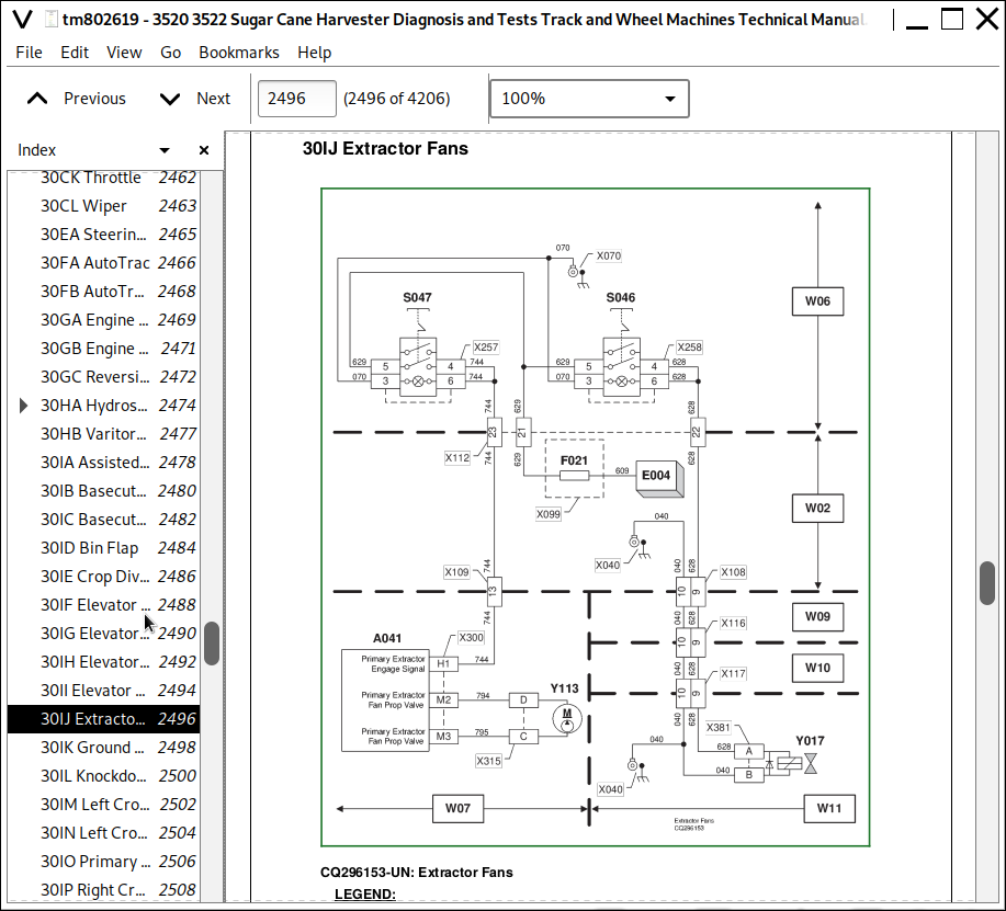
20IJ Extractor Fans
20IK Ground Drive High and Low for Track Machines
20IL Knockdown Roller Tilt
20IM Left Crop Divider Tilt
20IN Left Crop Divider Up and Down
20IO Primary Extractor Rotate
20IP Right Crop Divider Tilt
20IQ Right Crop Divider Up and Down
20IR Secondary Extractor Rotate
20IS Side Knife
20IT Topper Left and Right
20IU Topper Up and Down
20IV Height Indicator
20JA Backup Alarm
20JB Camera
20JC Displays and Gauges
20JD Hydraulic Oil Level and Temperature
20KA CAN Bus
Contour Base Cutter Height Control - Electrical Theory of Operation
Floating Crop Divider (FCD) - Electrical Theory of Operation
Group 30: Schematic
30AA Alternator and Battery
30AB Auxiliary Power
30AC Harvesting Functions
30AD Power Distribution
30AE Starting and Charging Circuit
30AF Engine Components with EGR
30AG Engine Components without EGR
30BA Beacon Light (European Option)
30BB Field Lights
30BC Road Lights
30BD Road Lights (European Option)
30BE Turn Signal, Warning and Hazard Lights
30BF Work Lights
30CA Air Conditioning and Heating
30CB Air Seat
30CC Fuel Gauge
30CD Fuel Transfer Pump
30CE Horn
30CF Park Brake
30CG PosiTrac for Wheel Machines
30CH Radio, Dome Light and Accessory
30CI Slow Maneuvering for Track Machines
30CJ Primary Extractor Tachometer
30CK Throttle
30CL Wiper
30EA Steering Position
30FA AutoTrac
30FB AutoTrac Resume Switch
30GA Engine Air Filter Restriction
30GB Engine Coolant Low
30GC Reversible Cooling Fan
30HA Hydrostatic Ground Drive
30HB Varitorq for Wheel Machines
30IA Assisted Basecutter
30IB Basecutter and Chopper Forward and Reverse
30IC Basecutter Up and Down
30ID Bin Flap
30IE Crop Divider Float
30IF Elevator Forward and Reverse and Start and Stop
30IG Elevator Swing
30IH Elevator Unload
30II Elevator Up and Down
30IJ Extractor Fans
30IK Ground Drive High and Low for Track Machines
30IL Knockdown Roller Tilt
30IM Left Crop Divider Tilt
30IN Left Crop Divider Up and Down
30IO Primary Extractor Rotate
30IP Right Crop Divider Tilt
30IQ Right Crop Divider Up and Down
30IR Secondary Extractor Rotate
30IS Side Knife
30IT Topper Left and Right
30IU Topper Up and Down
30IV Height Indicator
30JA Backup Alarm
30JB Camera
30JC Displays and Gauges
30JD Hydraulic Oil Level and Temperature
30KA CAN Bus
Contour Base Cutter Height Control — Electrical Schematic
Floating Crop Divider (FCD) — Electrical Schematic
Group 50: Diagnostic Procedure
50AA Alternator and Battery
50AB Auxiliary Power
50AC Harvesting Functions
50AD Power Distribution
50AE Starting and Charging Circuit
50AF Engine Components with EGR
50AG Engine Components without EGR
50BA Beacon Light (European Option)
50BB Field Lights
50BC Road Lights
50BD Road Lights (European Option)
50BE Turn Signal, Warning and Hazard Lights
50BF Work Lights
50CA Air Conditioning and Heating
50CB Air Seat
50CC Fuel Gauge
50CD Fuel Transfer Pump
50CE Horn
50CF Park Brake
50CG Positrac for Wheel Machines
50CH Radio, Dome Light and Accessory
50CJ Primary Extractor Tachometer
50CK Throttle
50CL Wiper
50EA Steering Position
50FA AutoTrac
50FB AutoTrac Resume Switch
50GA Engine Air Filter Restriction
50GB Engine Coolant Low
50GC Reversible Cooling Fan
50HA Hydrostatic Ground Drive
50HB Varitorq for Wheel Machines
50IA Assisted Basecutter
50IB Basecutter and Chopper Forward and Reverse
50IC Basecutter Up and Down
50ID Bin Flap
50IE Crop Divider Float
50IF Elevator Forward and Reverse and Start and Stop
50IG Elevator Swing
50IH Elevator Unload
50II Elevator Up and Down
50IJ Extractor Fans
50IK Ground Drive High and Low for Track Machines
50IL Knockdown Roller Tilt
50IM Left Crop Divider Tilt
50IN Left Crop Divider Up and Down
50IO Primary Extractor Rotate
50IP Right Crop Divider Tilt
50IQ Right Crop Divider Up and Down
50IR Secondary Extractor Rotate
50IS Side Knife
50IT Topper Left and Right
50IU Topper Up and Down
50IV Height Indicator
50JA Backup Alarm
50JB Camera
50JD Hydraulic Oil Level and Temperature
50KA CAN Bus
Section 245: Control Units
Group 05: General Reference
CAN Communication System Theory Of Operation
CAN Network Voltage Checks
CAN Communication Fault Checks
CAN System Diagnosis
Recall, Record, and Clear Codes
Programming Control Units
VIN Security Fault Diagnosis
Group 10: Calibrations or Operational and Preliminary Checks
Calibration Mode
Propulsion Steering Control (PSC) and Power Train Propulsion (PTP) Calibration
Propulsion Steering Control (PSC) and Power Train Propulsion (PTP) Control Unit Test
Crop Divider Position Left and Right Calibration
Crop Divider Pressure Calibration
Basecutter Target Height Calibration
Group 20: Theory of Operation
20A Assisted Basecutter Control Unit
20B Engine Control Unit
20C Propulsion Steering and Power Train Propulsion Control Units Power
20D Vehicle Control Unit
Improved Height Control Unit (IHU) - Controller Theory of Operation
Group 30: Schematic
30A Assisted Basecutter Control Unit
30B Engine Control Unit
30C Propulsion Steering and Power Train Propulsion Control Units Power
30D Vehicle Control Unit
Improved Height Control Unit (IHU) - Schematic
Group 50: Diagnostic Procedure
50AA Assisted Basecutter Control Unit Diagnostic Procedure
50B Engine Control Unit
50C Propulsion Steering and Power Train Propulsion Control Units Power
50D Vehicle Control Unit
PSC and PTP Control Units Test
Group PDU: Addresses for Cab Primary Display Control Unit
Viewing Diagnostic Addresses
PDU Control Unit Addresses
Group IHU: Addresses for Improved Height Control Unit
Viewing Diagnostic Addresses
IHU Control Unit Addresses
Address 197 - Crop Divider Lowering Current Cap
Address 198 - Crop Divider Raising Current Cap
Address 199 - Base cutter Raising Current Cap
Group PSC: Addresses for Propulsion Steering Control Unit
Viewing Diagnostic Addresses
PSC Control Unit Addresses
Group PTP: Addresses for Power Train Propulsion Control Unit
Viewing Diagnostic Addresses
PTP Control Unit Addresses
Group VCU: Addresses for Vehicle Control Unit
Viewing Diagnostic Addresses
VCU Control Unit Addresses
Group VTi: Addresses for Virtual Terminal (in Cab)
Viewing Diagnostic Addresses
VTi Control Unit Addresses
Section 249: Electrical Connector Information
Group 05: General Information
How to Use Connector Information
Wire Harness Circuit Coding
Group 40A: X001-X099
Description
X010 - Engine Ground
X030 - Cab Load Center Ground
X040 - Cab Load Center Ground
X041 - Elevator Ground
X050 - Engine Ground
XA55-1 - IHU Controller — Connector J1
XA55-2 - IHU Controller — Connector J2
XB045 - Left-Hand Crop Divider Transducer — Connector
XB046 - Right-Hand Crop Divider Transducer — Connector
XB057 - Base Cutter Pressure Transducer — Connector
XB058 - Left-Hand Crop Divider Position Sensor — Connector
XB060 - Right-Hand Crop Divider Position Sensor — Connector
XS095 - Contour Basecutter Height Control Enable Switch — Connector
XY003 - Right-Hand Crop Divider Raise Solenoid — Connector
XY004 - Right-Hand Crop Divider Lower Solenoid — Connector
XY028 - Left-Hand Crop Divider Raise Solenoid — Connector
XY029 - Left-Hand Crop Divider Lower Solenoid — Connector
XY045 - Basecutter Raise Solenoid — Connector
XY046 - Basecutter Lower Solenoid — Connector
XY085 - Left-Hand Crop Divider Accumulator solenoid — Connector
XY086 - Right-Hand Crop Divider Accumulator solenoid — Connector
X061 - Engine Ground
X070 - Cab Ground
X080 - Cab Load Center Ground
X090 - Cab Load Center Ground
X093 - Ground
X099 - Cab Load Center Fuse Block
Group 40B: X100-X199
X100 - Armrest Harness to Load Center Harness
X101 - Assisted Basecutter Harness to Load Center Harness
X102 - Armrest Harness to Steering Harness Connector
X103 - Cab Load Center Harness to Air Conditioning Harness
X104 - Load Center Harness to ABC Harness Connector
X105 - Cab Load Center Harness to Auxiliary Power Strip Harness
X106 - Cab Load Center Harness to Engine Harness
X107 - Cab Load Center Harness to Engine Harness
X108 - Cab Load Center Harness to Main Frame Harness
X109 - Cab Load Center Harness to Engine Harness
X110 - Engine 14 Harness Connector
X112 - Cab Load Center Harness to Cab Harness Connector
X113 - Cab Load Center Harness to Cab Harness Connector
X116 - Main Frame Harness to Main Frame Extension Harness Connector
X117 - Main Frame Extension Harness to Elevator Harness Connector
X120 - Main Frame Harness to Flasher Module Harness Connector
X121 - Engine Harness to Turn Signal Harness Connector
X123 - Air Conditioning Harness to Air Conditioning Compressor Switch Harness
X124 - Main Frame Harness to Flasher Relay Harness Connector
X125 - Flasher Module Harness to Flasher Relay Harness Connector
X126 - Engine Harness to Batteries (Positive)
X127 - Air Conditioning Harness to Air Seat
Group 40C: X200-X299
X200 - Topper Left/Right Switch
X201 - Primary Hood Rotate Switch
X202 - Crop Divider Float Switch
X203 - Secondary Hood Rotate Clock Wise Switch
X204 - Ground Drive Position Sensor
X205 - Emergency Stop Switch
X206 - Emergency Stop Switch
X207 - Emergency Stop Switch
X208 - Emergency Stop Switch
X209 - Hydraulic Reset Switch
X210 - Basecutter Forward/Reverse Switch
X211 - Left Crop Divider Tilt Switch
X212 - Right Crop Divider Tilt Switch
X213 - Elevator Up/Down Switch
X214 - Elevator Forward and Reverse Control Panel Switch
X215 - Left Side Knife On/Off Switch
X216 - Right Side Knife On/Off Switch
X217 - Throttle Switch
X218 - Auxiliary Power Outlet Ground
X219 - Auxiliary Power Outlet
X220 - Elevator Diode
X221 - Neutral Switch
X222 - Right Elevator Swing Pedal
X223 - Left Elevator Swing Pedal
X224 - Elevator On/Off Switch
X225 - Resume Switch
X226 - High/Low Pedal Switch
X227 - Elevator Diode
X228 - Cab Platform/Road Light Switch
X229 - Crop Divider Diode
X230 - Operators Present Switch
X231 - Auxiliary Power Strip (ORG)
X232 - Multifunction Control Lever (Previously Called Joystick)
X233 - Multifunction Control Lever (Previously Called Joystick)
X234 - Power Train Propulsion Control Unit (PTP)
X234 - Propulsion Steering Control (PSC)
X235 - Power Train Propulsion Control Unit (PTP)
X235 - Propulsion Steering Control (PSC)
X236 - Power Train Propulsion Control Unit (PTP)
X236 - Propulsion Steering Control (PSC)
X237 - Vehicle CAN Bus
X239 - Left Side Light
X240 - Engine Coolant Level Low Sensor
X241 - Right Side Light
X242 - Right Speaker
X243 - Left Speaker
X244 - Panel Light
X245 - Panel Light
X246 - Dome Light
X247 - Dome Light
X248 - Dome Light Switch
X249 - Primary Display Unit
X250 - Park Brake
X251 - AutoTrac Display
X252 - AUTEQ Alarm
X253 - AUTEQ Alarm
X254 - Right Wiper Motor
X255 - AUTEQ Display
X256 - Knockdown Roller Tilt Switch
X257 - Primary Extractor Switch
X258 - Secondary Extractor Switch
X259 - Reversing Cooling Fan Switch
X260 - PosiTrac Switch
X261 - Transport Switch (Track) / Slow Maneuvering Switch (Wheel)
X262 - High/Low Switch On Overhead Panel
X263 - Radio
X264 - Hazard Light Switch
X265 - Road Light Switch
X266 - Field Light Switch
X267 - Engine Work Light Switch
X268 - Beacon Light Switch
X269 - Left Wiper Motor
X270 - Camera
X271 - Center Wiper Motor
X272 - Wiper Timer
X273 - Wiper Timer
X274 - Wiper Timer
X275 - Wiper Timer
X276 - Wiper Timer
X278 - Flasher Module
X279 - Right Horn
X280 - Right Horn
X281 - CAN Bus Passive Terminator
X282 - Left Horn
X283 - Left Horn
X284 - Left Outside Road Lamp
X285 - Left Field Lamp
X286 - Left Inside Road Lamp
X287 - Left Beacon Light
X289 - Right Inside Road Lamp
X290 - Right Field Lamp
X291 - Right Outside Road Lamp
X292 - Universal AutoTrac (UAT)
X293 - Universal AutoTrac (UAT)
X294 - Pressure Sensors
X295 - Engine Work Light
X296 - Steering Input Dev
X297 - Left Crop Divider Up Solenoid
X298 - Transfer Pump Fuse
X299 - Vehicle Control Unit (VCU)
Group 40D: X300-X399
X300 - Vehicle Control Unit (VCU) J2
X301 - Vehicle Control Unit (VCU) J1
X302 - Basecutter Pump Solenoid
X303 - Unloading Solenoid
X304 - Topper Up and Down Solenoid
X305 - Primary Hood Rotate Clockwise and Counter Clockwise Solenoid
X306 - Right Crop Divider Up and Down Solenoid
X307 - Elevator Swing Right and Left Solenoid
X308 - Starter Relay
X309 - Starter Relay
X310 - Starter Relay
X311 - Starter Relay
X312 - Starter Relay Diode
X313 - Basecutter Pump Solenoid
X314 - Right Ground Drive Pump
X315 - Primary Extractor Pump
X316 - Left Ground Drive Pump
X317 - Chopper Pump Forward and Reverse Solenoid
X318 - Chopper Transducer
X319 - Alternator (Diode Side)
X320 - Vehicle Control Unit Fuse (VCU)
X321 - Vehicle Control Unit Fuse (VCU)
X322 - Feedroller Forward and Reverse Solenoid
X323 - Hydraulic Temperature Sender
X324 - Hydraulic Oil Level
X325 - Park Brake Diode
X326 - Hydraulic Filter Restriction
X327 - High/Low Solenoid
X328 - Variable Speed Solenoid
X329 - Brake Pressure Switch
X330 - Positrac Solenoid
X331 - Park Brake Solenoid
X332 - PosiTrac Diode
X336 - Starter Motor
X337 - Starter Motor
X338 - Compressor
X339 - Air Conditioning High Pressure Switch
X340 - Fuel Sensor
X341 - Side Washer Motor
X342 - Front Washer Motor
X343 - Proportional Coil (Right) Solenoid
X344 - Reverse Coil (top) Solenoid
X346 - Left Height Sensor
X347 - Right Height Sensor
X348 - Engine Air Filter Restriction Switch
X349 - Auxiliary Power Connection
X350 - CAN Bus Active Terminator
X351 - Engine Control Unit
X352 - Basecutter Press Sensor
X353 - Topper Left and Right Solenoid
X354 - Left Side Knife Solenoid
X355 - Right Side Knife Solenoid
X356 - Topper Collector Solenoid
X357 - Right Side Crop Divider Tilt Up and Down Solenoid
X358 - Left Side Crop Divider Tilt Up and Down Solenoid
X359 - Primary Tachometer Sensor
X360 - Knockdown Roller Tilt Connector
X361 - Basecutter Up Solenoid
X362 - Door Switch
X363 - Left Crop Divider Float Solenoid
X364 - Basecutter Down Solenoid
X365 - Right Speed Sensor
X366 - Right Height Sensor
X367 - Right Rear Tail and Turn Light Red
X368 - Reverse Light
X369 - Reverse Light
X370 - Left Rear Tail and Turn Light Red
X371 - Left Height Sensor
X372 - Left Speed Sensor
X373 - Left Elevator Light
X374 - Left Beacon Light
X375 - Elevator Proportional Valve Solenoid
X376 - Elevator Unload Solenoid
X377 - Secondary Hood Rotate Clockwise and Counter Clockwise Solenoid
X378 - Bin Flap In and Out Solenoid
X379 - Elevator Up and Down Solenoid
X380 - Elevator Solenoid Forward and Reverse
X381 - Secondary Extractor Solenoid
X382 - Right Beacon Light
X383 - Right Elevator Light
X384 - Elevator Diode Module
X385 - Elevator Diode Module
X386 - Elevator Diode Module
X387 - Flap Beater
X388 - License Plate Light
X389 - Reverse Alarm
X390 - Left Turn Signal
X391 - Right Turn Signal
X392 - Ignition Switch
X393 - Turn Signal Switch
X394 - Right-Hand Turn Amber Light
X395 - Left-Hand Turn Amber Light
X396 - Air Conditioning Compressor Switch
X397 - Center Wiper Switch
X398 - Side Wiper Switch
X399 - Wiper Diode
Group 40E: X400-X499
X401 - Primary Extractor
X402 - Primary Extractor
X403 - VariTorq Potentiometer
X404 - Blower Motor Switch
X405 - Right Crop Divider Float Solenoid
X422 - Auxiliary Power Strip (BLK)
X423 - Auxiliary Power Strip (RED)
X425 - Resistor Assembly
X426 - Recirculate Motor
X427 - Water Valve
X428 - Pressurizer Motor
X429 - Air Conditioning Thermostat Switch
X430 - Low Pressure Switch
X431 - Temperature Adjust
X432 - Pressurizer Motor Relay
X433 - Recirculate Motor Relay
X434 - Flasher Relay
X437 - ECU Fuse
X439 - Battery Disconnect Switch
X440 - Diagnostic Connector (Assisted Basecutter)
X441 - Assisted Basecutter Control Unit
X442 - Low Range Resistor
X443 - Assisted Basecutter On/Off Switch
X444 - High/Low Sensitivity Response Switch
X445 - System Error Light
X446 - Sensitivity/Response Potentiometer
X447 - Target Pressure
X448 - High Range Resistor
X449 - System Active Light
X450 - Left Brake Pedal
X451 - Right Brake Pedal
X455 - Battery
X456 - Battery
X457 - Battery
X458 - Battery
X459 - Battery Disconnect Switch
X494 - Battery Disconnect Cable (Ground Side)
Group 40F: X500-X599
X501 - Water-in-Fuel Sensor
X502 - Engine Crank Sensor
X503 - Oil Pressure Sensor
X504 - Fuel Transfer Pump
X505 - Fuel Pressure Sensor
X506 - Engine Cam Sensor
X508 - ECU Connector - Engine with EGR
X508 - ECU Connector - Engine without EGR
X509 - ECU Connector - Engine with EGR
X509 - ECU Connector - Engine without EGR
X510 - Pump Control Valve
X511 - Fuel Temp
X512 - Rail Pressure Sensor
X513 - Alternator Excitation
X514 - Coolant Temperature
X516 - EGR Mixed Air - Engine with EGR
X516 - Manifold Air Temp - Engine without EGR
X517 - Fuel Injector Connector
X518 - Manifold Air Pressure Sensor
X519 - Turbo Connection
X520 - EGR Exhaust
X521 - EGR Fresh Air
X522 - EGR Valve
X523 - VGT Speed Sensor
X524 - VGT Actuator
X525 - Comp Inlet Temp
X526 - Main Frame Harness to Engine Harness Connector
X528 - Rear Frame Harness to Engine Harness Connector
X529 - Rear Frame Harness to Engine Harness Connector
X530 - Cooling Harness to Engine Harness Connector
X531 - Auxiliary Power Connector
X532 - Secondary Display Unit A (SDUA)
X533 - GPS Receiver Connector
Section 250: Drive Train
Group 10: Calibrations or Operational and Preliminary Checks
Hydrostatic Pump Charge Pressure Check
Hydrostatic Pump Vacuum Pressure Check
Trim-Varitorq Potentiometer Calibration Procedure
Group 20: Theory of Operation
Theory of Operation
Hydrostatic Transmission Pump Theory of Operation
High Pressure Relief Valve
Charge Relief Valve
Pump Control Operation Neutral
Pump Control Operation Initial Movement
Flow / Pressure Specifications
Hydrostatic Transmission Control Operation
Track Harvester Hydrostatic Motor Description
Theory of Operation
Operation in Neutral
Operation in Forward
Wheel Harvester Hydrostatic Motor Description
Theory of Operation
Control Neutral
Displacement Regulation
Loop Flushing Components
Positrac Theory of Operation
Group 30: Schematic
Hydrostatic Drive Schematic
Group 50: Diagnostic Procedure
Hydrostatic System Checks
Left Ground Drive Pump Circuit Test
Right Ground Drive Pump Circuit Test
Propulsion Motor Shaft Speed Sensor Circuit Test
Trim-Varitorq Potentiometer Circuit Test
Varitorq Valve Circuit Test
Section 260: Steering and Brakes
Group 05: General Information
Brake Specifications
Front Suspension and Steering
Steering Test Procedure
Troubleshooting
Steering
Group 10: Calibrations or Operational and Preliminary Checks
Icons
Accessing Technician Mode
Harvester Forward and Reverse Lever Calibration Procedure (Multi-Function Lever)
SID Calibration Procedure
PWM Displacement Calibration Procedure
Trim-Varitorq Potentiometer Calibration Procedure
Field Deadband Calibration Procedure
Displacement Control Valve Neutral Adjustment
Calibration DTC List
Errors
Propulsion Motor Speed Sensor Installation Adjustment
Ground Speed Drive Lever Circuit Test
Lower Steering Wheel Position Potentiometer Circuit Test
Middle Steering Wheel Position Potentiometer Circuit Test
Upper Steering Wheel Position Potentiometer Circuit Test
Section 260A: Service Brakes
Group 20: Theory of Operation
Service Brakes
Group 30: Schematic
Service Brakes
Group 50: Diagnostic Procedure
Service Brakes
Section 270: Hydraulics
Group 05: General Information
Harvester Hydraulic System
Hydraulic System Testing Precautions
Hydraulic Specifications
Accumulators Calibration
Group 10: Calibrations or Operational and Preliminary Checks
Chopper Shaft Timing (Pinch) Adjustment
Crop Divider Control Valve Relief Test Procedure
Front Feed Roller Relief Test Procedure
Main Relief Test Procedure
Side Knife Relief Test Procedure
Group 20: Theory of Operation
20AA Crop Divider and Knock Down Rollers
20AB Crop Divider Lift (Non-Float and Float for Track Machines)
20AC Crop Divider Lift (Non-Float and Float for Wheel Machines)
20AD Elevator Swing
20AE Primary Hood Rotate
20AF Topper Lift
20AG Basecutter Lift
20AH Knock Down Tilt
20AI Crop Divider Tilt
20AJ Topper and Topper Collector and Side Knives
20BA Assisted Basecutter for Track Machines
20BB Assisted Basecutter for Wheel Machines
20CA Chopper and Basecutter High Performance
20CB Chopper and Basecutter Standard
20CC Front Feed Rollers
20CD Primary Extractor Fan
20CE Rear Feed Roller
20DA Elevator
20DB Elevator (Optional Variable Valve)
20EA Varitorq Ground Drive for Wheel Machines
20EB Ground Drive for Track Machines
20EC Hand Pump for Cab Tilt Assist
20ED Reversible Cooling Fan
Contour Base Cutter Height Control - Hydraulic Theory of Operation
Floating Crop Divider (FCD) - Hydraulic Theory of Operation
Group 30: Schematic
6-Bank Cylinder Block Functions with Float Hydraulic Schematic (Track Machine)
6-Bank Cylinder Block Functions without Float Hydraulic Schematic (Track Machine)
6-Bank Cylinder Block Functions with Float Hydraulic Schematic (Wheel Machine)
6-Bank Cylinder Block Functions without Float Hydraulic Schematic (Wheel Machine)
Assisted Base Cutter (ABC) Hydraulic Schematic (Track Machine)
Assisted Base Cutter (ABC) Hydraulic Schematic (Wheel Machine)
Base Cutter Hydraulic Schematic (High Performance)
Chopper Hydraulic Schematic (High Performance)
Chopper and Base Cutter Hydraulic Schematic (Standard)
Contour Base Cutter Height Control Hydraulic Schematic (Track Machine)
Contour Base Cutter Height Control Hydraulic Schematic (Wheel Machine)
Crop Divider and Knock Down Rollers Hydraulic Schematic
Elevator Hydraulic Schematic (Standard)
Elevator Hydraulic Schematic (Optional Variable Valve)
Floating Crop Divider (FCD) Hydraulic Schematic
Front Feed Rollers Hydraulic Schematic
Ground Drive Hydraulic Schematic (Track Machine)
Ground Drive 2-Speed Hydraulic Schematic (Track Machines)
Ground Drive Hydraulic Schematic (Wheel Machine)
Hand Pump for Cab Tilt Assist Hydraulic Schematic
Primary Extractor Fan Hydraulic Schematic
Rear Feed Roller Hydraulic Schematic
Reversible Cooling Fan Hydraulic Schematic
Topper and Side Knives Hydraulic Schematic
Group 50: Diagnostic Procedure
50AA Crop Divider and Knockdown Rollers
50AD Topper and Topper Collector and Side Knives
50AE Primary Extractor Hood
50AF Topper Function Hydraulic Check
50BA_BB Assisted Basecutter
50CA_CB Chopper and Basecutter
50CC_CE Feed Rollers
50CD Primary Extractor Fan
50DA Elevator
50EC Hand Pump for Cab Tilt Assist
50ED Reversible Cooling Fan
Section 279: Hydraulics Component Information
Group 40A: Accumulator
A003 - Elevator Lift Accumulator
A004 - Topper Lift Accumulator
A121 - Left Base Cutter Lift Accumulator
A122 - Right Base Cutter Lift Accumulator
A535 - Left-Hand Accumulator (IHU Equipped)
A536 - Right-Hand Accumulator (IHU Equipped)
Group 40C: Cylinder, Actuator, or Piston
C002 - Left-Hand Crop Divider Lift Cylinder
C003 - Right-Hand Crop Divider Lift Cylinder
C004 - Topper Cylinder
C006 - Knock Down Tilt Cylinder
C007 - Right-Hand Crop Divider Tilt Cylinder
C008 - Left-Hand Crop Divider Tilt Cylinder
C010 - Left Elevator Cylinder
C011 - Bin Flap Cylinder
C012 - Cab Tilt Cylinder
C013- Right Elevator Cylinder
C021 - Left Steering Cylinder
C022 - Right Steering Cylinder
C118 - Right Elevator Swing Cylinder
C119 - Left Elevator Swing Cylinder
C121 - Left Base Cutter Lift Cylinder
C122 - Right Base Cutter Lift Cylinder
Group 40D: Check Valve
D005 - Oil Cooler Check Bypass Valve
Group 40F: Filter
F059 - Triple In-Tank Filters
Group 40G: Valve Block, Assembly, or Gearcase
G003 - Remote Flushing Valve Assembly
G004 - Chopper Motor Assembly
G005 - Base Cutter Motor Assembly
G007 - Chopper and Base Cutter Pump Assembly (Standard)
G010 - Left Hydrostatic Pump Assembly
G011 - Right Hydrostatic Pump Assembly
G013 - 6-Bank Cylinder Function Valve Block
G014 - Auxiliary Tilt Function Valve Assembly (Optional)
G015 - Cushion Relief Valve Block
G017 - Primary Extractor Pump Assembly
G018 - Triple Relief Valve Assembly
G020 - Mud Flap Valve Assembly (Optional)
G021 - Topper Valve Assembly
G027 - Elevator Variable Valve Assembly (Optional)
G030 - Improved Height Control Valve
G032 - Elevator Drive Valve Assembly
G033 - 3 Section Pump Assembly
G035 - 5 Section Pump Assembly
G105 - Base Cutter Suspension Valve Assembly
G107 - PosiTrac Valve Assembly
G113 - Steering Priority Valve Assembly
G114 - Assisted Base Cutter Valve Assembly
G115 - Billet Selector Valve Assembly
G118 - Rear Feed Roller Rotation Valve Assembly
G119 - Crop Divider Rotation Valve Assembly
G120 - Front Feed Roller Rotation Valve Assembly
G121 - Reversible Cooling Fan Valve Assembly
G125 - Rear Feed Flow Divider Valve Assembly
G133 - Left Hydrostatic Motor Assembly
G134 - Right Hydrostatic Motor Assembly
G135 - Base Cutter Pump Assembly (High Performance)
G136 - Chopper Pump Assembly (High Performance)
G237 - Left Hydrostatic 2-Speed Motor Assembly
G238 - Right Hydrostatic 2-Speed Motor Assembly
G535 - Left-Hand Accumulator Valve Assembly (IHU Equipped)
G536 - Right-Hand Accumulator Valve Assembly (IHU Equipped)
Group 40H: Cooler
H001 - Oil Cooler
Group 40M: Motor
M004 - Right Side Knife Motor (Optional)
M014 - Left Outer Crop Divider Motor (Optional)
M015 - Left-Hand Crop Divider Motor
M016 - Right Upper Knockdown Motor (Optional)
M017 - Right Outer Crop Divider Motor (Optional)
M018 - Right-Hand Crop Divider Motor
M019 - Primary Hood Rotate Motor
M021 - Cooling Fan Motor
M022 - Primary Extractor Motor
M023 - Secondary Extractor Motor
M024 - Right Elevator Drive Motor
M026 - Secondary Extractor Hood Rotate Motor
M027 - Topper and Shredder Disc Motor
M028 - Left Side Knife Motor (Optional)
M029 - Left Adjustable Knockdown Roller Motor (Optional)
M030 - Right Adjustable Knockdown Roller Motor (Optional)
M031 - Radial Piston Motor
M032 - Bent Axis Piston Motor
M033 - Hydrostatic Motor
M034 - Hydrostatic Motor
M035 - Hydrostatic 2-Speed Motor
M036 - Hydrostatic 2-Speed Motor
M037 - Left Upper Knockdown Motor (Optional)
M038 - Lower Right Knockdown Motor
M039 - Left Elevator Drive Motor
M121 - Left Topper Collector Motor
M122 - Right Topper Collector Motor
Group 40P: Pump
P003 - Elevator Pump
P004 - Rear Feed Pump
P005 - Front Feed Pump
P006 - Topper Pump
P007 - Cooling Fan Pump
P008 - Crop Dividers Pump
P009 - Cylinder Function Pump
P010 - Hand Pump
P011 - Auxiliary Elevator Pump
P015 - Chopper and Base Cutter Pump (Standard)
P035 - Base Cutter Pump (High Performance)
P036 - Chopper Pump (High Performance)
P040 - Hydrostatic Pump
P041 - Hydrostatic Pump
Group 40R: Hydraulic Reservoir
R001 - Hydraulic Reservoir
Group 40V: Valve
V001 - Feed Control Valve
V002 - Chopper Relief Valve
V005 - Brake Valve
V006 - Varitorq Pressure Reducing Valve
V009 - Main relief valve
V010 - Suspension Valve
V011 - Throttle Valve
V012 - Steering Valve
V013 - Steering Priority Valve
V014 - Base Cutter Valve
V018 - Directional Control Valve (Rear Rollers)
V019 - Directional Control Valve (Front Rollers)
V021 - Reversible Cooling Fan Valve
V022 - Elevator Functions Main Relief Valve
V123 - Auxiliary Functions Main Relief Valve
V024 - Reversible Cooling Fan Main Relief Valve
V025 - Flow Divider Valve
V030 - Contour Base Cutter Height Control Valve
V031 - Left-Hand Crop Divider Float Valve (IHU Equipped)
V032 - Right-Hand Crop Divider Float Valve (IHU Equipped)
V035 - Accumulator Bleed Off Valve
V036 - Accumulator Bleed Off Valve
V132 - Base Cutter Check Valve
Group 40Y: Solenoid Valve
Y003 - Right Crop Divider Up Solenoid
Y004 - Right Crop Divider Down Solenoid
Y005 - Elevator Forward Solenoid Valve
Y006 - Elevator Reverse Solenoid Valve
Y007 - Elevator Up Solenoid Valve
Y008 - Elevator Down Solenoid Valve
Y009 - Variable Speed Solenoid Valve
Y010 - PosiTrac Solenoid Valve
Y012 - Park Brake Solenoid Valve
Y013 - Topper Up Solenoid Valve
Y014 - Topper Down Solenoid Valve
Y015 - Left Side Knife Solenoid Valve
Y016 - Right Side Knife Solenoid Valve
Y017 - Secondary Extractor Solenoid
Y018 - Elevator Swing Right Solenoid Valve
Y019 - Elevator Swing Left Solenoid Valve
Y020 - Topper Left Solenoid Valve
Y021 - Topper Right Solenoid Valve
Y022 - Topper Collector Solenoid Valve
Y023 - Feed Roller Reverse Solenoid Valve
Y024 - Feed Roller Forward Solenoid Valve
Y025 - Base Cutter Pump FWD Solenoid Valve
Y026 - Base Cutter Pump REV Solenoid Valve
Y027 - Mud Flap Solenoid Valve
Y028 - Left Crop Divider Up Solenoid
Y029 - Left Crop Divider Down Solenoid
Y030 - Secondary Hood Rotate Clockwise Solenoid Valve
Y031 - Secondary Hood Rotate Counter Clockwise Solenoid Valve
Y032 - Left Crop Divider Tilt Up Solenoid Valve
Y033 - Left Crop Divider Tilt Down Solenoid Valve
Y034 - Right Crop Divider Tilt Up Solenoid Valve
Y035 - Right Crop Divider Tilt Down Solenoid Valve
Y036 - Bin Flap Out Solenoid Valve
Y038 - Elevator Unload Solenoid Valve
Y039 - High/Low Solenoid Valve
Y040 - Primary Hood Rotate Counter Clockwise Solenoid Valve
Y041 - Primary Hood Rotate Clockwise Solenoid Valve
Y042 - Unloading Solenoid Valve
Y043 - Knock Down Roller Tilt Down Solenoid Valve
Y044 - Knock Down Roller Tilt Up Solenoid Valve
Y045 - Base Cutter Up Solenoid
Y046 - Base Cutter Down Solenoid
Y047 - Base Cutter Up Solenoid Valve (ABC Equipped)
Y048 - Base Cutter Down Solenoid Valve (ABC Equipped)
Y049 - Reverse Cooling Fan Coil Solenoid Valve
Y050 - Proportional Cooling Fan Coil Solenoid Valve
Y051 - Chopper Pump FWD Solenoid Valve
Y052 - Chopper Pump REV Solenoid Valve
Y053 - Elevator Proportional Valve Solenoid Valve
Y085 - Left-Hand Crop Divider Accumulator Solenoid Valve (IHU Equipped)
Y086 - Right-Hand Crop Divider Accumulator Solenoid Valve (IHU Equipped)
Y111 - Right Hydrostatic Pump Solenoid Valve
Y112 - Left Hydrostatic Pump Solenoid Valve
Y113 - Primary Extractor Pump Solenoid Valve
Section 290: Operator Station
Group 05: General
About this Section
Section 290A: Air Suspension Seat and Armrest
Group 20: Disassemble and Assemble
Remove and Install Armrest
Remove and Install Armrest Control Cover
Remove Multi-Function Lever
Remove Seat from Suspension
Remove Air Seat Suspension System
Disassemble and Assemble Operator Seat Air Suspension Assembly
Group 30: Schematic
Operator Seat-Exploded View
Operator Seat Air Suspension Assembly-Exploded View
Section 290B: Air Conditioning and Heating
Group 10: Calibrations or Operational and Preliminary Checks
Refrigerant Precautions
R134A Component Oil Charge
R134A Refrigerant Recover, Recycling and Charging System Installation Procedure
Recover R134A System
Evacuate R134A System
Charge R134A System
Safety Precautions
Group 20: Theory of Operation
Theory of Operation
Air Conditioning and Heating Theory of Operation
Air Pressurizing Circuit Theory of Operation
Air Conditioning Circuit Theory of Operation
Air Conditioning and Heater Air Flow Operation
Group 30: Schematic
Air Conditioning and Heating
Group 50: Diagnostic Procedure
Air Conditioning System Test
Section 299: Special Tools
Group 05: Special Tools and Part Numbers
Ground Drive Tools
![]()