
John Deere Combines 1450 CWS, 1550 CWS, 1450 WTS, 1550 WTS Diagnosis and Tests Service Manual (TM4904)
Complete service Diagnostics and Tests manual with Electrical Wiring Diagrams for John Deere Combines 1450 CWS, 1550 CWS, 1450 WTS, 1550 WTS (S.N. from 048751), with all the shop information to maintain, diagnose, and rebuild like professional mechanics.
John Deere Combines 1450 CWS, 1550 CWS, 1450 WTS, 1550 WTS workshop Operation and Tests manual includes:
* Numbered table of contents easy to use so that you can find the information you need fast.
* Detailed sub-steps expand on repair procedure information
* Numbered instructions guide you through every repair procedure step by step.
* Troubleshooting and electrical service procedures are combined with detailed wiring diagrams for ease of use.
* Notes, cautions and warnings throughout each chapter pinpoint critical information.
* Bold figure number help you quickly match illustrations with instructions.
* Detailed illustrations, drawings and photos guide you through every procedure.
* Enlarged inset helps you identify and examine parts in detail.
Total Pages: 1,119 pages
File Format: PDF/EPUB/MOBI/AZW (PC/Mac/Android/Kindle/iPhone/iPad; bookmarked, ToC, Searchable, Printable)
Language: English
TM4904 - John Deere Combines 1450 CWS, 1550 CWS, 1450 WTS, 1550 WTS Technical Manual (Diagnosis and Tests).PDF
TM4904 - John Deere Combines 1450 CWS, 1550 CWS, 1450 WTS, 1550 WTS Technical Manual (Diagnosis and Tests).EPUB
MAIN SECTIONS
Foreword
References in this manual
Safety
Safety Information
Diagnostics
AHC-Automatic Head Control
Electrical System
General Information
Electrical System Schematics
Power Feed / Starter Motor
Engine Shut Off-1550
Engine Shut Off-1450
Electronic Motor - Focus Level 4-CWS/WTS
Fuse Tester
Instruments
Straw Distributor Adjustment-CWS/WTS
Lighting, Windshield Washer
Radio, PY - PX
Alarm Module No. 1 / Shut Off Function
Warning Module No. 2
Cigarette Lighter
Light Function
Intermittent Light Function
Intermittent Indicator Lights
Air Conditioning System
Outside Mirror Adjustment -CWS/WTS (option)
Work Lights
Straw Warning Device
Brake Lights, Reel Speed Adjustment
Engaging Threshing / Unloading Auger
Head / Reverser Engage
INFO-TRAK™ Monitor/ Drive Shaft Speed Monitor
Harvest Performance Monitor
Threshing Cylinder, Concave and Fan Adjustment
Head Control Circuit Board
Unloading Auger Swing
Four Wheel Drive-1450/1550 (option)
Area counter-CWS/WTS
Gearshift Lock-CWS/WTS
Reverse Travel Alarm / Cleaning Shoe Lights
Head Calibration Procedures
Wire Harnesses
Connector Data
Power Train
Specification
Checking Parts for Wear
Testing the Hydrostatic System
Transmission
Four Wheel Drive
Two Speed Four Wheel Drive
Brakes, Steering and Rear Axle
Brake System
Drum Brakes
Steering System
Hydraulic System
General Information
Hydraulic Schematic
Reel Hydraulic Motor
Hydraulic Pump Drive
Hydraulic Control Valve
Hydraulic System Troubleshooting
Cab
Cab and Operator`s Seat
Air Conditioning and Heating
Ventilation and Heating - Troubleshooting
Operational Tests and Troubleshooting
Air Conditioning System Operation
TABLE OF CONTENTS......1
Section 205: Safety......28
Group 05: Safety Information......28
Live With Safety......30
Work in Clean Area......31
Work In Ventilated Area......32
Wear Protective Clothing......33
Service Machines Safely......34
Prepare for Emergencies......35
Avoid High-Pressure Fluids......1135
Service Accumulator Systems Safely......37
Park Machine Safely......38
Transporting the Combine Safely......39
Handle Fluids Safely-Avoid Fires......40
Prevent Battery Explosions......41
Prevent Acid Burns......42
Support Machine Properly......44
Remove Paint Before Welding or Heating......45
Avoid Heating Near Pressurized Fluid Lines......46
Illuminate Work Area Safely......47
Replace Safety Signs......48
Use Proper Lifting Equipment......49
Service Tires Safely......50
Practice Safe Service......51
Use Proper Tools......52
Dispose of Waste Properly......53
Section 211: Diagnostics......54
Group AHC: AHC-Automatic Head Control......1124
AHC 200-Calibration Memory Fault......54
AHC 201-Head Height Calibration Fault......54
AHC 202-Head Float Calibration Fault......54
AHC 203-Head Sensors Not Responding......54
AHC 209-Head Slow Raise Valve Solenoid Circuit......54
AHC 210-Head Slow Lower Valve Solenoid Circuit......54
AHC 211-Head Fast Raise Valve Solenoid Circuit......54
AHC 212-Head Fast Lower Valve Solenoid Circuit......54
AHC 213-Left Lateral Tilt Valve Solenoid Circuit......54
AHC 214-Right Lateral Tilt Valve Solenoid Circuit......54
AHC 215-Flex Pressure Divert Valve Solenoid Circuit-600 Series Flex Head......54
AHC 216-Accumulator Shut Off Valve Solenoid Circuit- 300 and 600 Series Rigid Head......54
AHC 218-Sensor Power Feed......54
AHC 220-Height Control Setting-600 Series Rigid Head......54
AHC 221-Float Control Setting-300 and 600 Series Rigid Head......54
AHC 224-Feeder House Angle Sensor-300 and 600 Series Rigid Head......54
AHC 225-Left-hand Tilt Sensor-600 Series Flex Head......54
AHC 226-Right-hand Tilt Sensor-600 Series Flex Head......54
AHC 227-Lift Cylinder Pressure Sensor-300 and 600 Series Rigid Head......54
AHC 232-Raise/Lower Switch......54
AHC 233-Manual Tilt Switch......54
AHC 234-Manual Flex Pressure Switch-600 Series Flex Head......54
AHC 235-Reel Manual Raise/Lower Switch......54
AHC 236-Reel Manual Extend/Retract Switch......54
AHC 240-Height Sensor-600 Series Flex Head......54
AHC 241-Reel Raise/Lower Position Sensor-600 Series Flex Head......54
AHC 242-Reel Fore/Aft Position Sensor-600 Series Flex Head......54
AHC 243-Reel Raise Valve Drive Circuit......54
AHC 244-Reel Lower Valve Drive Circuit......54
AHC 245-Reel Extend Valve Drive Circuit......54
AHC 246-Reel Retract Valve Drive Circuit......54
Section 240: Electrical System......87
Group 05: General Information......87
Electrical Circuit Malfunction......106
Open Circuit......107
Grounded Circuit......108
Shorted Circuit......109
How to Read a Functional Schematic......110
Symbols in System Schematics......111
Symbols in System Schematics (Continued)......115
Symbols in System Schematics (Continued)......115
Symbols in System Schematics (Continued)......115
Group 10: Electrical System Schematics......87
Sections......117
Electrical Components (By Section)......118
Electrical Components (Alphanumerical Order)......125
Section 1, 2A, 2B and 3......137
Section 4, 5, 6, and 7......138
Section 8 and 9......139
Section 10 and 11......140
Section 12 and 13......141
Section 14, 15 and 16......142
Section 17, 18 and 19......143
Section 20......144
Section 21......145
Section 22......146
Section 23 and 25......147
Section 26-S/no. (048751 - 049815)......148
Section 26-S/no. (049816 - )......149
Section 27, 28, 29, 30 and 31......150
Group 15A: Power Feed / Starter Motor......87
Specification......1224
Operational Information......321
Operational Theory......1079
Functional Schematic, Section 1 (SE1)......155
Group 15B: Engine Shut Off-1550......88
Operational Information......321
Operational Theory......1079
Functional Schematic, Section 2A (SE 2A)......160
Group 15C: Engine Shut Off-1450......88
Operational Information......321
Operational Theory......1079
Functional Schematic, Section 2B (SE 2B)......164
Group 15D: Electronic Motor - Focus Level 4-CWS/WTS......88
Operational Information......321
Operational Theory......1079
Functional Schematic, Section 3 (SE3)......168
Group 15E: Fuse Tester......172
Operational Information......321
Fuse Tester......172
Functional Schematic, Section 4 (SE 4)......173
Group 15F: Instruments......88
Operational Information......321
Operational Theory......1079
Functional Schematic, Section 5 (SE 5)......177
Group 15G: Straw Distributor Adjustment-CWS/WTS......88
Operational Information......321
Operational Theory......1079
Functional Schematic, Section 6 (SE 6)......182
Group 15H: Lighting, Windshield Washer......88
Operational Information......321
Operational Theory......1079
Functional Schematic, Section 7 (SE 7)......186
Group 15I: Radio, PY - PX......88
Operational Information......321
Operational Theory......1079
Functional Schematic, Section 8 (SE 8)......190
Group 15J: Alarm Module No. 1 / Shut Off Function......89
Functional Schematic, Section 9 (SE 9)......192
Group 15K: Warning Module No. 2......89
Functional Schematic, Section 10 (SE 10)......194
Group 15L: Cigarette Lighter......89
Operational Information......321
Functional Schematic, Section 11 (SE 11)......197
Group 15M: Light Function......89
Operational Information......321
Operational Theory......1079
Functional Schematic, Section 12 (SE 12)......201
Group 15N: Intermittent Light Function......89
Operational Information......321
Operational Theory......1079
Functional Schematic, Section 13 (SE 13)......206
Group 15O: Intermittent Indicator Lights......89
Operational Information......321
Operational Theory......1079
Functional Schematic, Section 14 (SE 14)......211
Group 15P: Air Conditioning System......89
Operational Information......321
Operational Theory......1079
Functional Schematic, Section 15 (SE 15)......215
Group 15Q: Outside Mirror Adjustment -CWS/WTS (option)......89
Operational Information......321
Operational Theory......1079
Functional Schematic, Section 16 (SE 16)......220
Group 15R: Work Lights......89
Operational Information......321
Operational Theory......1079
Functional Schematic, Section 17 (SE 17)......226
Group 15S: Straw Warning Device......90
Operational Information......321
Operational Theory......1079
Functional Schematic, Section 18 (SE 18)......231
Group 15T: Brake Lights, Reel Speed Adjustment......236
Operational Information......321
Operational Theory......1079
Reel Speed Adjustment - Switch Positions......235
Reel Speed Adjustment......236
Diagnostic Mode......239
Reel Speed Control Board Error Codes......240
Dipswitch Operation Adjustment......242
Dipswitch Positions......243
Functional Schematic, Section 19 (SE 19)......244
Group 15U: Engaging Threshing / Unloading Auger......1172
Operational Information......321
Operational Theory......1079
Functional Schematic, Section 20 (SE 20)......249
Group 15V: Head / Reverser Engage......90
Operational Information......321
Operational Theory......1079
Functional Schematic, Section 21 (SE 21)......253
Group 15X: INFO-TRAK™ Monitor/ Drive Shaft Speed Monitor......90
Operational Information - INFO-TRAK™ Monitor......255
Input of Machine-Specific Data......256
Software Version......258
Tire Radius Code......259
Machine Code......261
Transmission Speed Ratio Code......262
Determining Tire Radius......263
Engine Impulse Code......264
Error Codes, INFOTRAK Monitor......265
Operational Information, Speed Monitoring System......266
Operational Theory......1079
Functional Schematic, Section 22 (SE 22)......270
Group 15Y: Harvest Performance Monitor......273
Operational Information......321
Harvest Performance Monitor......273
Preliminary Adjustments to Combine......275
Starting Up the Harvest Performance Monitor......276
Operational Adjustment of Harvest Performance Monitor Sensors......281
Operational Adjustment of Harvest Performance Monitor (Continued)......280
Operational Adjustment of Harvest Performance Monitor Sensors......281
Operational Check of Harvest Performance Monitor......282
Functional Schematic, Section 23 (SE 23)......285
Group 15Z: Threshing Cylinder, Concave and Fan Adjustment......91
Operational Information......321
Operational Theory......1079
Functional Schematic, Section 25 (SE 25)......289
Group 15AA: Head Control Circuit Board......91
Operational Information......321
Operational Theory......1079
Functional Schematic, Section 26 (SE 26)-S/no. (048751 - 049815)......293
Functional Schematic, Section 26 (SE 26)-S/no. (049816 - )......295
Group 15AB: Unloading Auger Swing......1158
Operational Information......321
Operational Theory......1079
Functional Schematic, Section 27 (SE 27)......304
Group 15AC: Four Wheel Drive-1450/1550 (option)......91
Operational Information......321
Operational Theory......1079
Functional Schematic, Section 28 (SE 28)......308
Group 15AD: Area counter-CWS/WTS......91
Operational Information......321
Functional Schematic, Section 29 (SE 29)......311
Group 15AE: Gearshift Lock-CWS/WTS......92
Operational Information......321
Operational Theory......1079
Functional Schematic, Section 30 (SE 30)......315
Group 15AF: Reverse Travel Alarm / Cleaning Shoe Lights......92
Operational Information......321
Operational Theory......1079
Functional Schematic, Section 31 (SE 31)......319
Group 15AG: Head Calibration Procedures......92
Operational Information......321
Automatic Float Control for 300 and 600 Series Rigid Heads-CWS/WTS......322
Return to Cut Position for 300 and 600 Series Rigid Head-CWS/WTS......326
Head Automatic Height Control- 600 Series Rigid Head-CWS/WTS......328
Multifunction Control Handle Functions......331
Head Control System Troubleshooting Tips......332
Section 250: Power Train......1029
Group 05: Specification......1224
Hydrostatic Transmission......1121
Hydrostatic Drive Components-1450/1550......1033
Hydrostatic Drive Components-CWS/WTS......1035
Group 10: Checking Parts for Wear......1029
Inspection of Parts......1038
Insufficient Lubrication......1039
Contamination with Abrasive Substances......1040
Cavitation......1041
Excessive rotation......1042
Shaft Seal Inspection......1043
Inspection of Thrust Plate......1045
Inspection of Fixed Swashplate......1046
Inspection of Piston Shoe......1047
Inspection of Piston Retainer......1049
Inspection of Cylinder Block......1051
Inspection of Bearing Plate......1052
Inspection of Valve Plate......1056
Inspection of Bearing and Race......1059
Inspection of Servo Piston......1060
Inspection of Drive Shaft......1061
Group 15: Testing the Hydrostatic System......1029
Specification......1224
Special Tools......1222
Hydrostatic Pump Pre-Charge Pressure......1065
Retract Pressure Relief Valve......1067
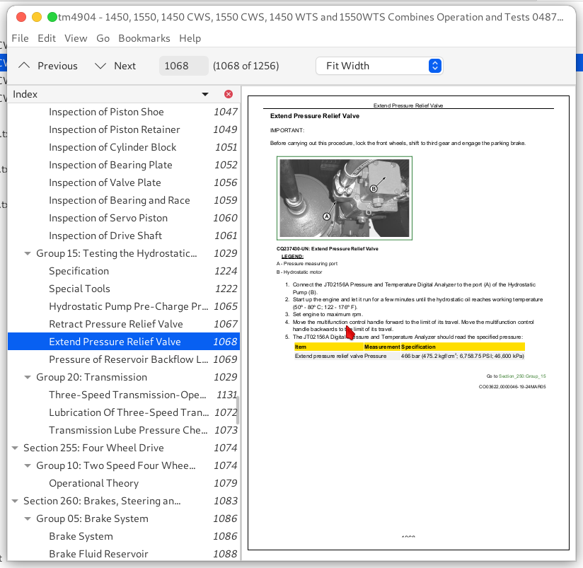
Extend Pressure Relief Valve......1068
Pressure of Reservoir Backflow Limiter Valve......1069
Group 20: Transmission......1029
Three-Speed Transmission-Operation......1131
Lubrication Of Three-Speed Transmission......1072
Transmission Lube Pressure Check......1073
Section 255: Four Wheel Drive......1074
Group 10: Two Speed Four Wheel Drive......1074
Operational Theory......1079
Section 260: Brakes, Steering and Rear Axle......1083
Group 05: Brake System......1086
Brake System......1086
Brake Fluid Reservoir......1088
Adjusting Foot Brakes......1089
Parking Brake......1090
Brake Master Cylinder......1091
Pressure Equalizing Valve......1094
Group 10: Drum Brakes......1098
Drum Brakes......1098
Group 15: Steering System......1083
Hydraulic Schematic......1101
Hydrostatic Unit......1176
Operation Of the Metering Element Impeller......1104
Manual Operation Of The Unit......1106
Section 270: Hydraulic System......1108
Group 05: General Information......1108
Testing Precautions......1111
Hydraulic Symbols......1112
Group 10: Hydraulic Schematic......1101
General......1118
Hydrostatic Transmission......1121
Hydrostatic Transmission with Two Speed Four Wheel Drive......1122
Control......1124
Chaff Spreader-CWS/WTS......1126
Reel......1127
Drives......1128
Group 15: Reel Hydraulic Motor......1108
Operation......1131
Group 20: Hydraulic Pump Drive......1108
Operation of the Automatic Belt Tensioning Device for the Hydraulic Pump Drive......1133
Group 25: Hydraulic Control Valve......1108
Avoid High-Pressure Fluids......1135
Precautions to be Taken Prior to Disassembling A Valve......1136
Pressure Relief Valves......1137
Description of Hydraulic System......1138
Triple Hydraulic Pump......1140
Functions of Valves on the Block......1141
Hydraulic Control Valve Block - Description of Units......1143
Adjustment of Head Raise Speed......1146
Units of the Hydraulic Control Valve Block......1147
Return to reservoir......1148
Hydraulic Reverser......1149
AHC-DIAL-A-MATIC......1150
Head Raise/Lower-Manual......1151
Input Port / Flow Splitter......1152
Reel Raise/Lower......1154
Reel Extend/Retract......1155
Threshing Cylinder POSI-TORQ™......1156
Head Lateral Tilt......1157
Unloading Auger Swing......1158
Control Block Relief Valve Setting......1159
Primary Circuit Relief Valve Setting (Head and Reverser)......1160
Secondary Circuit Relief Valve Setting......1162
Reel Drive Circuit Relief Valve......1164
Steering Circuit Relief Valve......1165
Group 30: Hydraulic System Troubleshooting......1225
Hydraulic Valve Control Block......1169
Unloading Auger......1172
Threshing Cylinder Posi-Torq Unit......1173
Hydrostatic Steering......1174
Reel Variable-Speed Drive Unit Flow Divider Valve......1175
Hydrostatic Unit......1176
Hydraulic Reel Motor......1178
Pump Failures......1179
Section 290: Cab......1184
Group 05: Cab and Operator's Seat......1181
Cab......1184
Cab Air Filter......1185
Air Intake And Distribution......1186
Operator's Seat And Passenger's Seat......1187
Mechanical Adjustment of Operator's Seat Position-CWS/WTS......1188
Mechanical Adjustment of Seat Position......1189
Adapting Seat to Operator’s Weight......1190
Air Comfort Seat (Option)......1191
System Diagnosis of Mechanical Seat......1192
Group 10: Air Conditioning and Heating......1181
Compressor and Drive......1194
Air Conditioning and Heating Unit-Heating Unit, CWS/WTS only......1195
Air Conditioning Housing......1196
Air Conditioning Housing (Left-hand Side)......1197
Air Conditioning Housing (Right-hand Side)......1198
Air Conditioning Housing (Hose Connections)......1199
Temperature Control Switch With Sensor......1200
Air Conditioning Housing in the Open Position......1201
Evaporator With Expansion Valve......1249
Air Control Flap (Machines with Heater Unit only)......1203
Cab Rear and Lateral Wall Connectors and Hoses......1205
Heater Control Valve (CWS and WTS) and Air Conditioning System Low Pressure Switch......1206
Group 15: Ventilation and Heating - Troubleshooting......1225
Ventilation and Heating......1209
Group 20: Operational Tests and Troubleshooting......1225
Test Sequence......1212
Air Conditioning and Heating Operational Checks......1213
Safety in the Workplace......1217
Handling Refrigerant......1218
In the event of an Emergency......1219
Storage of Containers of Refrigerant......1220
R134a Refrigerant......1241
Special Tools......1222
Specification......1224
Troubleshooting......1225
Explanation Of Checks......1226
Air Conditioning System Checks......1227
Pressure Deviations......1235
Group 25: Air Conditioning System Operation......1131
Principle Of Heat Exchange......1239
R134a Refrigerant......1241
Layout Of Refrigerant Circuit......1242
Description Of Refrigerant Circuit Function......1243
Description Of Refrigerant Circuit Function (Continued)......1245
Compressor......1246
Condenser......1247
Receiver-Dryer......1248
Expansion Valve......1249
Thermostat Switch......1251
Evaporator......1252
Temperature Control Switch and Compressor Switch......1253
John Deere Combines 1450 CWS, 1550 CWS, 1450 WTS, 1550 WTS Diagnosis and Tests Service Manual (TM4904)
![]()