
John Deere W540, W550, W650, W660, T550, T560, T660, T670 Combines (MY14) Repair Service Manual (TM406219)
Complete service repair manual for John Deere Combines (MY2014) Models W540, W550, W650, W660, T550, T560, T660, T670 with Wide Cab (World-Wide Edition), with all the shop information to maintain, repair, and service like professional mechanics.
John Deere W540, W550, W650, W660, T550, T560, T660, T670 Combines (MY14) workshop service repair manual includes:
* Numbered table of contents easy to use so that you can find the information you need fast.
* Detailed sub-steps expand on repair procedure information
* Numbered instructions guide you through every repair procedure step by step.
* Notes, cautions and warnings throughout each chapter pinpoint critical information.
* Bold figure number help you quickly match illustrations with instructions.
* Detailed illustrations, drawings and photos guide you through every procedure.
* Enlarged inset helps you identify and examine parts in detail.
TM406219 - John Deere W540, W550, W650, W660, T550, T560, T660, T670 Combines (MY14) Technical Manual (Repair).PDF
TM406219 - John Deere W540, W550, W650, W660, T550, T560, T660, T670 Combines (MY14) Technical Manual (Repair).EPUB
Total Pages: 2,430 pages
File Format: PDF/EPUB/MOBI/AZW (PC/Mac/Android/Kindle/iPhone/iPad; bookmarked, ToC, Searchable, Printable)
Language: English
MAIN SECTIONS
Foreword
General Information
Safety
Specifications
General Repair Information
Fuel, Lubricants, Coolant and Capacities
Engine
Remove and Install Engine
Cooling System
Fuel System and Air Intake System
Air Intake System
Diesel Fuel System
Electrical System
Harness and Connector Repair
Batteries
Wiring Harness Routing
Power Distribution and Location of Control Units
Switches, Sensors and Motors
Electromagnetic Valves
Lights
Operator's Station
Windshield Wiper
Alternator
Starting Motor
GreenStar™ Components
Power Train
Transmission and Differential - Three-Speed Transmission
Hydrostatic System - Three-Speed Transmission
Transmission and Differential - ProDrive™ Transmission
Hydrostatic Drive Pump - ProDrive™ Transmission
Hydrostatic Drive Motor - ProDrive™ Transmission
Final Drives
Cam Lobe Motor
HillMaster™ System
Steering and Brakes
Steering System
Brakes - Three-Speed Transmission
Brakes - ProDrive™ Transmission
Hydraulic System
Hydraulic Oil Reservoir
Hydraulic Pumps
Hydraulic Valves
Hydraulic Cylinders
HillMaster™ II Hydraulic Cylinders
Motor
Accumulators
Separator Shell
Gull Wing Doors
Ladder
Operator's Station
Air Conditioning System (R134a)
System Components
Operator's Cab
Feeder House Repair
Feeder House
Upper Shaft and Slip Clutch
Feeder House Drives and Reverser Gear Case
Auto Header Control™ Tilt Cylinder and Frame
HillMaster™ II Tilt Cylinder and Frame
Separator, W-Series Combines
Separator Repair
Beater (T Series)
Separator Rotor/Separator Grate (T Series)
Separator Grate (T Series)
Overshot Beater/Stripper (T Series)
Cylinder Drives
Walkers, Walker Shafts and Walker Return Pan
Straw Chopper and Chaff Spreader
Shoe Supply Augers, Cleaning Fan, Chaffer/Sieve Frame
Tailings Elevator and Augers
Tailings Elevator and Auger Slip Clutch (T Series)
Primary Countershaft
Header Electromagnetic Clutch
Grain Tank and Unloading System
Grain Tank Cross Augers
Auger System Drives
Vertical Auger and Lower Gear Case
Horizontal Auger and Gear Case
Clean Grain Elevator and Loading Auger Gear Case
Grain Tank and Extensions
Engine Gear Case and Control Valve
Engine Gear Case and Valve
Special Tools
Essential Special Tools
Recommended Special Tools
tm406219 - W540, W550, W650, W660,T550, T560, T660, T670Combines - MY2014, Wide Cab - Repair -: (Worldwide Edition)
Table of Contents
Foreword
Section 10: General Information
Group 05: Safety
Recognize Safety Information
Follow Safety Instructions
Understand Signal Words
Prevent Battery Explosions
Handling Batteries Safely
Wait Before Opening High-Pressure Fuel System
Prepare for Emergencies
Handle Fluids Safely—Avoid Fires
Prevent Acid Burns
Avoid High-Pressure Fluids
Protect Against High Pressure Spray
Prevent Machine Runaway
Park Machine Safely
Live With Safety
Install All Guards
Support Machine Properly
Wear Protective Clothing
Work in Clean Area
Service Machines Safely
Service Cooling System Safely
Stay Clear of Rotating Drivelines
Work In Ventilated Area
Illuminate Work Area Safely
Replace Safety Signs
Use Proper Lifting Equipment
Service Tires Safely
Avoid Heating Near Pressurized Fluid Lines
Avoid Hot Exhaust
Remove Paint Before Welding or Heating
Use Proper Tools
Construct Dealer-Made Tools Safely
Practice Safe Maintenance
Protect Against Noise
Dispose of Waste Properly
Avoid Harmful Asbestos Dust
Use Adequate Service Facilities
Servicing Electronic Control Units
Welding Near Electronic Control Units
Precautions for Welding
Keep Electronic Control Unit Connectors Clean
Clean Exhaust Filter Safely
Handle Fuel Safely—Avoid Fires
Handle Starting Fluid Safely
Exhaust Filter Cleaning
Group 10: Specifications
Operating Speeds
Specifications - W540 Combine
Specifications - W550 Combine
Specifications - W650 Combine
Specifications - W660 Combine
Specifications - T550 Combine
Specifications - T560 Combine
Specifications - T660 Combine
Specifications - T670 Combine
Length Dimensions
Width Dimensions
Metric Bolt and Screw Torque Values
Unified Inch Bolt and Screw Torque Values
Assemble and Install Flat Face Seal Fittings - All Pressure Applications
Torque Chart for Metric Flat Face Seal Fittings - Standard Pressure Applications
Torque Chart for Metric Flat Face Seal Fittings - High Pressure Applications
Torque Chart for SAE Flat Face Seal Fittings - Standard Pressure Applications
Torque Chart for SAE Flat Face Seal Fittings - High Pressure Applications
Assemble and Install Four-Bolt Flange Fittings - All Pressure Applications
Torque Values for SAE Four-Bolt Flange - Standard Pressure Applications
Torque Values for SAE Four-Bolt Flange - High Pressure Applications
Group 15: General Repair Information
Tune-Up and Adjustment
Care and Maintenance of Belts
Defective Belts
Prevent Hydraulic System Contamination
Check Oil Lines and Fittings
Basic Electrical Component Handling / Precautions For Vehicles Equipped With Computer Controlled Systems
Programming Control Units
Group 20: Fuel, Lubricants, Coolant and Capacities
Handle Fuel Safely—Avoid Fires
Handling and Storing Diesel Fuel
Lubricity of Diesel Fuel
Diesel Fuel
Testing Diesel Fuel
BioDiesel Fuel
Minimizing the Effect of Cold Weather on Diesel Engines
John Deere Break-In Plus™ Engine Oil — Interim Tier 4, Final Tier 4, Stage IIIB, and Stage IV
Diesel Engine Coolant (engine with wet sleeve cylinder liners)
Supplemental Coolant Additives
Drain Intervals for Diesel Engine Coolant
Operating in Warm Temperature Climates
Testing Diesel Engine Coolant
Additional Information About Diesel Engine Coolants and John Deere LIQUID COOLANT CONDITIONER
John Deere COOL-GARD™ II Coolant Extender
Additional Information About Diesel Engine Coolants and John Deere COOL-GARD™ II Coolant Extender
Liquid Coolant Conditioner
Diesel Engine Oil — Interim Tier 4, Final Tier 4, Stage IIIB, and Stage IV
Hydrostatic Drive System, Main Hydraulic System and Main Engine Gear Case Oils
Transmission, Final Drives, Feeder House Reverser, Primary Countershaft, Loading Auger Elevator and Dual-Range Cylinder Drive Gear Cases
Grease
Lubricant Storage
Mixing of Lubricants
Alternative and Synthetic Lubricants
Oilscan™ and CoolScan™
Capacities
Section 20: Engine
Group 05: Remove and Install Engine
Essential or Recommended Tools
Specifications
John Deere Engine Repair—Use CTM
Remove Engine—Non IT4
Install Engine—Non IT4
Remove Engine—6.8 L (Interim Tier 4)
Install Engine—6.8 L (interim Tier 4)
Remove Engine—9.0 L (Interim Tier 4/Stage III B)
Install Engine—9.0 L (Interim Tier 4/Stage III B)
Remove and Install Flywheel Pilot Bearing
Remove and Install Aftertreatment Device Assembly
Disassemble and Assemble Aftertreatment Device
Group 15: Cooling System
John Deere Engine Repair—Use CTM
Remove and Install Rotary Screen
Remove and Install Rotary Screen Drive
Rotary Screen Drive Exploded View (Interim Tier 4/Stage III B)
Remove and Install Rotary Screen Idler Arm and Sheaves
Rotary Screen Idler Arm and Sheaves Exploded View (Interim Tier 4/Stage III B)
Remove and Install Rotary Screen Brush Kit (Optional)
Rotary Screen Exploded View (Interim Tier 4/Stage III B)
Remove and Install Rotary Screen
Remove and Install Rotary Screen Door
Vacuum Fan Assembly Exploded View (Interim Tier 4/Stage III B)
Remove and Install Vacuum Fan Jackshaft
Remove and Install Vacuum Fan Assembly
Remove and Install Vacuum Fan Impeller
Remove Cooling Package (Interim Tier 4/Stage III B)
Install Cooling Package (Interim Tier 4/Stage III B)
Remove and Install Oil Cooler (Interim Tier 4/Stage III B)
Remove and Install Radiator
Remove Radiator (Interim Tier 4/Stage III B)
Install Radiator (Interim Tier 4/Stage III B)
Variable Speed Fan Drive and Driven Assembly Exploded View (Interim Tier 4/Stage III B)
Replace Variable Speed Fan Drive Belt (Interim Tier 4/Stage III B)
Remove and Install Variable Speed Fan Drive Assembly (Interim Tier 4/Stage III B)
Disassemble and Assemble Variable Speed Fan Drive Assembly (Interim Tier 4/Stage III B)
Remove and Install Variable Speed Fan Driven Assembly (Interim Tier 4/Stage III B)
Disassemble and Assemble Variable Speed Fan Driven Assembly (Interim Tier 4/Stage III B)
Lubricate Variable Speed Fan Drive and Driven Assemblies (Interim Tier 4/Stage III B)
Viscous Fan Drive Assembly (6.8 L Interim Tier 4)
Remove and Install Viscous Fan Drive Assembly (6.8 L Interim Tier 4)
Test Radiator
Test Radiator Cap
Replace Thermostats
Repair or Replace Water Pump
Section 30: Fuel System and Air Intake System
Group 05: Air Intake System
Specifications
John Deere Engine Repair—Use CTM
Remove and Install Turbocharger
Turbocharger Repair
Remove and Install Charge Air Cooler
Remove and Install Charge Air Cooler (Interim Tier 4/Stage III B)
Cleaning Charge Air Cooler
Group 10: Diesel Fuel System
Specifications
Remove and Install Fuel Tank
Remove and Install Fuel Tank Shutoff Valve
Replace Fuel Filter (6.8-Liter Engine)
Replace Water Separator Filter (6.8-Liter Engine)
Remove and Install Fuel Filters (9.0-Liter Engine)
Fuel Filters — Removal (Interim Tier 4/Stage III B)
Fuel Filters — Installation (Interim Tier 4/Stage III B)
Clean the Fuel Precleaner (9.0-Liter Engine)
Flush Fuel Precleaner (Heavy-Duty; Option)
Clean Fuel Precleaner (Heavy-Duty; Option)
Replace Fuel Precleaner (Heavy-Duty; Option)
Remove and Install Fuel Prefilter (Interim Tier 4/Stage III B)
Remove and Install Fuel Cooler (Interim Tier 4/Stage III B)
Section 40: Electrical System
Group 05: Harness and Connector Repair
Essential or Recommended Tools
Other Material
Use Electrical Insulating Compound
Using High-Pressure Washers
Electrical System Visual Inspection
Basic Electrical Component Handling / Precautions for Vehicles Equipped with Computer Controlled Systems
Electrical Connector / Wiring Harness Handling and Repair
Repair Procedure R-A
Repair Procedure R-B
Repair Procedure R-C
Repair Procedure R-D
Repair Procedure R-E
Repair Procedure R-F
Repair Procedure R-G
Repair Procedure R-I
Repair Procedure R-J
Repair Procedure R-K
Repair Procedure R-M
Repair Procedure R-N
Repair Procedure R-AE
Repair Procedure R-AF
Repair Procedure R-AG
Repair Procedure R-AH
Repair Procedure R-AI
Repair Procedure R-AJ
Repair Procedure R-AK
Repair Procedure R-AL
Repair Procedure R-AR
Repair Procedure R-AS
Repair Procedure R-AT
Group 10: Batteries
Prevent Battery Explosions
Handling Batteries Safely
Avoid Damage to Electrical System
Checking Electrolyte Specific Gravity
Remove and Install Battery
Charging Batteries
Group 15: Wiring Harness Routing
Replace Harness
Cab Main Wiring Harness
Cab Main Wiring Harness
Cab Roof Wiring Harness
Location of Wiring Harnesses, L.H. Side of Machine
Location of Wiring Harnesses, R.H. Side of Machine
Group 20: Power Distribution and Location of Control Units
Fuse Identification
Diodes on 6.8 and 9.0 Liter Engines
Remove and Install HVAC Power Module
Remove and Install Cab Power Modules
Remove and Install R.h. and L.h. Power Module
Location of Control Units
Location of Control Units (Interim Tier 4/Stage III B)
Ground Points
Group 25: Switches, Sensors and Motors
Essential or Recommended Tools
Other Material
Location of Shaft Speed Sensors, L.H. Side of Machine
Location of Shaft Speed Sensors, R.H. Side of Machine
Remove And Install Low Shaft Speed Sensor
Remove and Install Full Grain Tank Sensor
Remove and Install Tailings Sensor
Remove and Install VisionTrak VisionTrak is a trademark of Deere & Company. Sensors (Shoe/Separator), B21, B22, B23 and B24
Remove and Install Concave Position Sensor, B17
Remove and Install Sensors for Header Height (B9) and Tilt (B20)
Remove and Install Back-Up Alarm Switch
Remove and Install Hillmaster Sensor, B70
Remove and Install Hydraulic Reservoir Temperature Sensor
Location of Sensors on ProDrive Transmission
Location of Switches on ProDrive Transmission
Location of Sensors on Push Button Shift Transmission
Location of Switches on Hydrostatic Pump— ProDrive Transmission
Remove and Install Park Brake Switch
Remove and Install Ground Speed Sensor
Remove and Install Hydro Charge Pressure Switch
Remove and Install Pressure Switch B55 of Header Control
Remove and Install Coolant Low Switches S55 and S57
Remove and Install Fuel Level Sensor B67
Remove and Install Air Filter Restriction Switch
Remove and Install Fuel Transfer Pump Pressure Sensor—9.0 L Engine
Remove and Install Engine Gear Case Temperature and Pressure Switches
Remove and Install Engine Oil Pressure Sensor
Remove and Install Compressor Inlet Temperature Sensor
Remove and Install Evaporator Temperature Sensor
Remove and Install Air Temperature Sensors
Remove and Install Pump Position Sensor
Remove and Install Engine Speed Sensor
Remove and Install Water in Fuel Sensor
Remove and Install Variable Speed Fan Driven Sensor
Remove and Install Exhaust Gas Recirculation (EGR) Exhaust Gas Temperature and Fresh Air Temperature Sensors
Remove and Install Intake Manifold Pressure and Exhaust Gas Recirculation (EGR) Mixed Gas Temperature Sensor
Remove and Install Turbocharger Speed Sensor
Remove and Install Fuel Temperature Sensor
Remove and Install Fuel Rail Pressure Sensor—9.0 L Engine
Remove and Install Multi-Function Lever Feed Rate Sensor
Remove and Install Steering Input Device Sensor
Remove and Install Switches for Shoe Adjustment, Shoe Lights and Service Lights
Remove and Install Chaffer and Sieve Adjusting Motors
Remove and Install Miscellaneous Motors
Remove and Install Wheel Angle Sensor
Remove and Install Particulate Filter Sensors
Group 30: Electromagnetic Valves
Electromagnetic Valves on Main Valve Block
Electromagnetic Valves on Header Height Control Valve Block
Electromagnetic Valves on Feeder House
Electromagnetic Valves in Engine Compartment
Electromagnetic Valve on Three Speed Transmission
Electromagnetic Valves on ProDrive Transmission
Electromagnetic Valves on Push Button Shift Transmission
Four-Wheel Drive Electromagnetic Valves
Electromagnetic Valves on Engine Fan Clutch
Group 35: Lights
Safety Rules When Replacing Halogen Bulbs
Safety Rules When Replacing High Intensity Discharge (HID) Xenon Bulbs
Cab Halogen Round Headlight Bulb Replacement and Adjustment
Cab Halogen Oval Light Bulb Replacement and Adjustment
High Intensity Discharge (HID-Xenon) Light Replacement and Adjustment
Remove and Install High Intensity Discharge (HID-Xenon) Ballasts (If Equipped)
Header Flood Light Bulb Replacement (If Equipped)
Low Beam Driving Light Bulb Replacement and Adjustment (If Equipped)
Remove and Install Header Flood Light Housing (If Equipped)
Remove and Install Low Beam Driving Light Housing (If Equipped)
Rotary Beacon Bulb Replacement
Auxiliary Field, Access Door, Grain Tank, Unload Auger and Work Light Bulb Replacement
Side Finder (Optional) Light Bulb Replacement
Hazard/Warning Light Bulb Replacement
Dome Light Bulb Replacement
Group 40: Operator's Station
Instruments and Controls Identification
Remove and Install Overhead Console
Remove and Install Radio
Remove and Install Radio Speaker
Remove and Install Radio Antenna Base Assembly
Remove and Install Mobile Radio Antenna
Remove and Install Modular Telematics Gateway Antenna
Replace Corner Post Display
Remove and Install Auxiliary Power Outlet Strip
Armrest Console Connector Locations
Remove and Install Side Console
Remove and Install Multi-Function Lever
Remove and Install Armrest Display Unit
Remove and Install Header and Separator Engage Switches
Remove and Install Dial-A-Speed and Active Header Control Switches
Remove and Install Armrest Console Switch Panel
Remove and Install Multi-Function Control Lever Position Switches
Remove and Install Ignition Switch
Remove and Install Starting Aid Switch
Remove and Install Steering Column Lever
Remove and Install Remote Mirrors
Remove and Install Remote Mirror Adjustment Switch
Remove and Install Heated Mirror Switch
Remove and Install Hands Free Microphone
Remove and Install Map Light Assembly
Group 45: Windshield Wiper
Specifications
Remove and Install Windshield Wiper Arms
Remove and Install Windshield Wiper Motor
Remove and Install Windshield Washer
Adjust Windshield Wiper Arms
Group 50: Alternator
Essential or Recommended Tools
Specifications
John Deere Engine Accessories—Alternator Repair
Remove and Install Alternator and Alternator Belt
Remove and Install Alternator and Alternator Belt (Interim Tier 4/Stage III B)
Remove and Install Alternator Pulley
Group 55: Starting Motor
Essential or Recommended Tools
Specifications
John Deere Starting Motor Repair
Remove and Install Starting Motor
Remove and Install Starting Motor (Interim Tier 4/Stage III B)
Group 60: GreenStar™ Components
Specifications
Other Material
Remove and Install GreenStar Mass-Flow Sensor
Remove and Install GreenStar Moisture Sensor
Disassemble and Assemble GreenStar Moisture Sensor
Remove and Install GreenStar Moisture Sensor Actuator
Remove and Install GreenStar Moisture Sensor Circuit Board
Remove and Replace GreenStar Moisture Sensor Lower Cell Assembly
Position Receiver and Base Exploded View
Remove and Install Position Receiver
Disassemble and Assemble Position Receiver
Section 50: Power Train
Group 05: Transmission and Differential - Three-Speed Transmission
Other Material
Specifications
Remove Transmission
Remove and Repair Shifter Forks and Shifter Cam
Install Shifter Forks and Shifter Cam
Remove and Install Transmission Lube Pump
Remove and Install Suction Screen
Transmission Components
Disassemble and Repair Transmission
Assemble Transmission
Install Transmission
Remove and Install Gearshift Lever and Linkage
Adjust Gearshift Linkage
Remove Transmission (PBST)
Remove and Repair Shifter Forks (PBST)
Install Shifter Forks (PBST)
Remove and Install Transmission Lube Pump (PBST)
Push Button Shift Transmission (PBST) Exploded View
Disassemble and Repair Transmission (PBST)
Assemble Transmission (PBST)
Remove and Install Park Brake Actuator (PBST)
Disassemble and Assemble Park Brake Actuator (PBST)
Valve Block Shifter (PBST) Exploded View
Disassemble and Assemble Transmission Shift Valve (PBST)
Install Transmission (PBST)
Group 10: Hydrostatic System - Three-Speed Transmission
Essential or Recommended Tools
Service Equipment and Tools
Other Material
Specifications
Serial Number Plate
Clean Hydrostatic Motor and Pump
Flushing the Hydrostatic System
Remove and Install Hydrostatic Motor
Disassemble Hydrostatic Motor
Inspect Parts
Lack of Lubrication
Abrasive Contamination
Cavitation
Over Speeding
Inspect Thrust Plate
Inspect Fixed Swashplate
Inspect Piston Slipper
Inspect Piston Retainer
Inspect Cylinder Block
Inspect Bearing Plate
Inspect Valve Plate
Inspect Bearing and Race
Inspect Servo Piston
Inspect Drive Shaft
Replace Cylinder Block Spring
Assemble Motor
Remove and Install Motor Valve Block (Manifold)
Repair Motor Valve Block
Remove and Install Hydrostatic Pump
Disassemble Drive Pump
Assemble Drive Pump
Replace High-Pressure Line Center Pivot O-Rings
Disassemble and Assemble End Cover
Repair Displacement Control Valve
Displacement Control Valve with Feed Rate - Exploded View
Disassemble and Assemble DisplacementControl Valve with Feed Rate (Optional)
Electronic Proportional Displacement Control Valve Neutral Adjustment
Install Hydrostatic Pump
Remove and Install Charge Pump
Repair Charge Pump
Remove and Install Hydrostatic Control Cable
Adjust Hydrostatic Control Linkage
Adjust Neutral Position of Displacement Control Valve
Start-Up Procedure After Hydrostatic System Repair
Group 15: Transmission and Differential - ProDrive™ Transmission
Service Equipment and Tools
Other Material
Specifications
Drain Oil
Remove Transmission
Transmission Components—Overview
Remove Brake Assemblies
Disassemble Brake Assemblies
Assemble Brake Assemblies
Install Brake Assemblies
Remove and Install Park Brake Housing
Disassemble and Assemble Park Brake
Remove and Install Differential Module
Disassemble Differential Module (With Differential Lock)
Assemble Differential Module (With Differential Lock)
Remove Gear-Shift Planetary Drive With Clutch (Forward/Reverse)
Disassemble and Assemble Gear-Shift Planetary Drive With Clutch (Forward/Reverse)
Install Gear-Shift Planetary Drive With Clutch (Forward/Reverse)
Remove and Install Countershaft
Repair Countershaft
Countershaft—Exploded View
Remove and Install Filter Screen
Replace Proportionator Pump Bushing
Assemble Transmission
Install Transmission
Group 20: Hydrostatic Drive Pump - ProDrive™ Transmission
Service Equipment and Tools
Recommended Special Tools
Specifications
General View
Serial Number Plate
Clean Variable Pump
Remove and Install Hydrostatic Pump
Replace Drive Shaft Seal
Replace Boost Pump Seal
Replace Control Piston Cover Seals
Replace Boost Pressure Valve Seals
Replace Pressure Cut Off Valve Seals
Remove and Install Control Unit
Disassemble Pump
Disassemble Cylinder Assembly
Disassemble Control Piston
Inspection Notes
Assemble Pump
Install Rotary Group
Adjust Zero Position
Group 25: Hydrostatic Drive Motor - ProDrive™ Transmission
Service Equipment and Tools
Specifications
Identification of Axial Piston Machine
Remove and Install Hydrostatic Drive Motor
General View
Replace Cover Plate Seal
Replace Cover Plate Seal
Replace Port Plate Control Seals
Remove and Install Port Plate Control Rod
Disassemble and Assemble Flushing Valve
Disassemble Port Plate
Assemble Port Plate
Disassemble Rotary Group
Inspection Notes
Assemble Rotary Group
Adjust Rotary Group
Group 30: Final Drives
Essential or Recommended Tools
Service Equipment and Tools
Other Material
Specifications
Remove and Install Final Drive
Disassemble and Assemble Final Drive
Adjust Spindle Bearing (Preferred Method)
Adjust Spindle Bearing (Alternate Method)
Group 35: Cam Lobe Motor
Essential or Recommended Tools
Service Equipment and Tools
Other Material
Specifications
Flush Cam Lobe Motors
Remove Cam Lobe Motor
Install Cam Lobe Motor
Remove and Install Cam Lobe Motor Control Valve
Disassemble and Assemble Cam Lobe Motor Control Valve
Remove and Install Steering Yoke
Disassemble and Assemble Pivot Pins, Bushings, and Seals
Remove and Install Solenoid Valve and Valve Block
Remove and Install Displacement Control Valve
Remove and Install Cam and Piston Carrier
Remove and Install Valve Block Seals
Remove and Install Axle Bearings and Seals
Group 40: HillMaster™ System
HillMaster II Rocker Assembly - LH Side
HillMaster II Rocker Assembly - RH Side
Section 60: Steering and Brakes
Group 05: Steering System
Essential or Recommended Tools
Other Material
Specifications
Remove Steering Valve
Steering Valve—Without AutoTrac Option
Disassemble Steering Valve—Without AutoTrac Option
Assemble Steering Valve—Without AutoTrac Option
Disassemble Steering Valve—With AutoTrac Option
Electrohydraulic Steering Valve—With AutoTrac Option
Assemble Steering Valve—With AutoTrac Option
Install Steering Valve
Steering Column-Exploded View
Disassemble and Assemble Steering Column
Replace Telescoping Shaft Bearings
Remove and Install Steering Cylinder
Repair Steering Cylinder
Adjust Toe-In
Remove and Install Steering Tie Rod
Remove and Install Rear Spindle Assembly - Heavy-Duty Version without Rear-Wheel Drive
Disassemble and Assemble Rear Spindle Assembly - Heavy-Duty Version without Rear-Wheel Drive
Remove and Install Rear Axle Pivot Bushing
Adjust Rear Axle
Group 10: Brakes - Three-Speed Transmission
Service Equipment and Tools
Other Material
Specifications
Deglazing Brake Linings
Park Brake Release (PBST)
Remove and Install Brake Drum (PBST)
Remove Brake Shoe (PBST)
Remove Brake Drum
Remove Brake Shoes - Heavy Duty Version
Recondition Brakes - Heavy Duty Version
Assemble Brakes (PBST)
Assemble Brakes - Heavy Duty Version
Install Brake Drum
Remove and Install Master Cylinder
Brake Fluid Reservoir
Bleeding Brake System
Disassemble and Assemble Master Cylinder (Double Bleed Screw)
Adjust Master Cylinder
Bleed Brake System (Double Bleed Screw)
Remove and Install Slave Cylinders
Disassemble and Assemble Slave Cylinder
Disassemble and Assemble Brake Pedals
Disassemble and Assemble Parking Brake Pedal
Adjust Park Brake Pedal
Group 15: Brakes - ProDrive™ Transmission
Service Equipment and Tools
Other Material
Specifications
Remove and Install Hydraulic Service Brake Valve
Disassemble and Assemble Hydraulic Service Brake Valve
Adjust Hydraulic Service Brake Valve
Bleed Service Brakes
Disassemble and Assemble Brake Pedals
Repair Brake Disks
Remove and Install Accumulator
Section 70: Hydraulic System
Group 05: Hydraulic Oil Reservoir
Service Equipment and Tools
Specifications
Remove and Install Reservoir
Remove and Install Reservoir (Interim Tier 4/Stage III B)
Flushing the Hydraulic System
Flushing the Reel/Belt Pickup Drive System
Start-Up Procedure After Hydrostatic System Repair
Group 10: Hydraulic Pumps
Essential or Recommended Tools
Other Material
Specifications
Remove Main Hydraulic Pump
Marking Hydraulic Pump
Disassemble Hydraulic Pump
Replace Seal
Triple Main Hydraulic Pump—Exploded View (Three Speed Transmission)
Quad Main Hydraulic Pump—Exploded View (ProDrive Transmission)
Assemble Triple Main Hydraulic Pump—Three Speed Transmission
Assemble Quad Main Hydraulic Pump—ProDrive Transmission
Install Main Hydraulic Pump
Remove Proportionator Motor—ProDrive Transmission
Proportionator Motor Exploded View
Disassemble and Assemble Proportionator Motor
Install Proportionator Motor—ProDrive Transmission
Remove Spreader Pump
Disassemble Spreader Pump
Spreader Pump - Exploded View
Assemble Spreader Pump
Install Spreader Pump
Group 15: Hydraulic Valves
Essential or Recommended Tools
Other Material
Specifications
Remove and Install Hydraulic Valve Block
Disassemble and Assemble Hydraulic Valve Stack
Remove and Install Header Height Control Valve Block
Disassemble and Assemble Header Height Control Valve Block
Remove and Install ProDrive Transmission Control Valve
Remove and Repair Valves From ProDrive Transmission Control Valve
Install Valves In ProDrive Transmission Control Valve
Remove and Install Service Brake Pressure Regulating Valve—ProDrive Transmission
Remove and Install Variable Speed Fan Drive Valve Block
Disassemble and Assemble Variable Speed Fan Drive Valve Block
Feeder House Multi-Coupler Check Valves - General View
Disassemble, Inspect and Assemble Feeder House Multi-Coupler
Remove and Install Left Front Valve Block
Disassemble and Assemble Left Front Valve Block
Group 20: Hydraulic Cylinders
Specifications
Remove and Install Header Lift Cylinder
Disassemble and Assemble Header Lift Cylinder
Remove and Install Unloading Auger Swing Cylinder
Adjust Unloading Auger Swing Cylinder
Remove and Install Unloading Auger Drive Cylinder
Adjust Unloading Auger Drive Cylinder
Group 21: HillMaster™ II Hydraulic Cylinders
Special Tool (Dealer-Fabricated)
Other Material
Specifications
General Information
Remove and Install HillMaster II Cylinder
Components of HillMaster II Cylinder
Check Valve Components
Components of Compensating Valve
Compensating Valve Installed in Piston
Attachment of HillMaster II Cylinders
Group 25: Motor
Remove and Install Chaff Spreader Motor
Group 30: Accumulators
Service Equipment and Tools
Accumulator (General Information)
Check Header Float System Accumulator
Accumulator Charge Pressure
Section 80: Separator Shell
Group 05: Gull Wing Doors
Other Material
Remove and Install Gull Wing Doors
Composite Panel Repair
Group 10: Ladder
Remove and Install Ladder
Adjustment the Ladder
Section 90: Operator's Station
Group 05: Air Conditioning System (R134a)
Essential or Recommended Tools
Air-Conditioning Service Unit
Service Equipment and Tools
Other Material
Specifications
Service Parts Kits
Hose and Tubing O-Ring Connection Torques
Discharge and Recovery of Air Conditioning Refrigerant
Remove and Install Compressor—6.8 L Engine
Remove and Install Compressor
Remove and Install Compressor—9.0 L Engine (Interim Tier 4/Stage III B)
Test Volumetric Efficiency
Leak Testing Air Conditioning System With Dye
Test Shaft Seal Leakage
Disassemble and Assemble Compressor Clutch
Check Clutch Hub Clearance
Inspect Compressor Manifold
Disassemble, Inspect, and Assemble Compressor
Remove and Install Compressor Relief Valve
System Information
Flush Air Conditioning System
Purge Air Conditioning System
Evacuate Air Conditioning System
Compressor Oil Information
Determine Correct Oil Charge
Check Refrigerant Oil Charge
Charge Air Conditioning System
Group 10: System Components
Essential or Recommended Tools
Other Material
Specifications
Heating, Ventilating, and Air Conditioning System—HVAC (General Information)
Remove and Install Receiver/Dryer
Remove and Install Pressurizer Blower Motor
Remove and Install Recirculator Fan Motor Driver
Remove and Install Recirculator Fan Motor
Remove and Install Actuator Valves
Remove and Install Climate Control Unit
Remove and Install Heater Core
Remove Condenser
Remove Condenser (Interim Tier 4/Stage III B)
Repair Condenser
Install Condenser
Install Condenser (Interim Tier 4/Stage III B)
Remove and Install Evaporator
Replace Expansion Valve
Remove and Install Evaporator Temperature Sensor
Replace Air Conditioning High/Low Pressure Switch
Replace Air Temperature Sensors
Group 15: Operator's Cab
Specifications
Remove Cab
Install Cab
Remove and Install Cab Windshield
Remove and Install Emergency Exit Glass
Remove and Install Rear Window
Remove and Install Lower Cab Fascia
Remove and Install Front Portion of Cab Roof
Remove and Install Rear Portion of Cab Roof
Remove and Install Cab Inner Roof
Remove and Install Cab Headliner
Remove and Install Operator Seat
Remove and Install Operator Air Seat Suspension
Remove and Install Armrest Control Pivot
Remove and Install Operator Presence Switch
Operator Seat Exploded View
Disassemble and Assemble Operator Seat Air Suspension Assembly
Remove and Install Refrigerator
Remove and Install Cab Door
Disassemble and Assemble Cab Door Exploded View
Cab Door Latch Striker
Section 110: Feeder House Repair
Group 05: Feeder House
Other Material
Specifications
Remove and Install Feeder House
Remove and Install Conveyor Chain
Measure Conveyor Chain Wear
Remove Conveyor Chain Link
Replace Conveyor Chain Slats
Replace Conveyor Chain Wear Strips
Adjust Drum Height
Remove and Install Conveyor Drum
Conveyor Drum Exploded View - HillMaster II
Conveyor Drum Exploded View - Standard Combines and Auto Header Control Tilt
Remove And Install Mid-Floor Assembly
Remove And Install Sub-Floor Assembly
Remove and Install Pea Kit Sub-Floor Assembly (Optional)
Feed Plate Support - Exploded View
Group 10: Upper Shaft and Slip Clutch
Specifications
Remove and Install Top Shaft Supports
Disassemble and Assemble Conveyor Top Shaft
Group 15: Feeder House Drives and Reverser Gear Case
Other Material
Specifications
Top Shaft Idler - Exploded View
Feeder House Countershaft and Tensioner - Exploded View
Remove and Install Reverser Gear Case
Feeder House Reverser Gear Case - Exploded View
Disassemble and Assemble Feeder House Reverser Gear Case
Remove and Install Reverser Shift Piston
Remove and Install Lower Shaft
Disassemble and Assemble Conveyor Drive Chain, Tightener and Guides
Group 20: Auto Header Control™ Tilt Cylinder and Frame
Specifications
Auto Header Control Tilt Cylinder Hoses and Fittings - Exploded View
Remove and Install Auto Header Control Tilt Cylinder
Feeder House Shell, Wear Plates and Seals, Location
Tilt Beam and Closure Plates,Location
Remove and Install Tilt Frame
Remove and Install Tilt Beam
Adjust Fore-Aft Turnbuckles
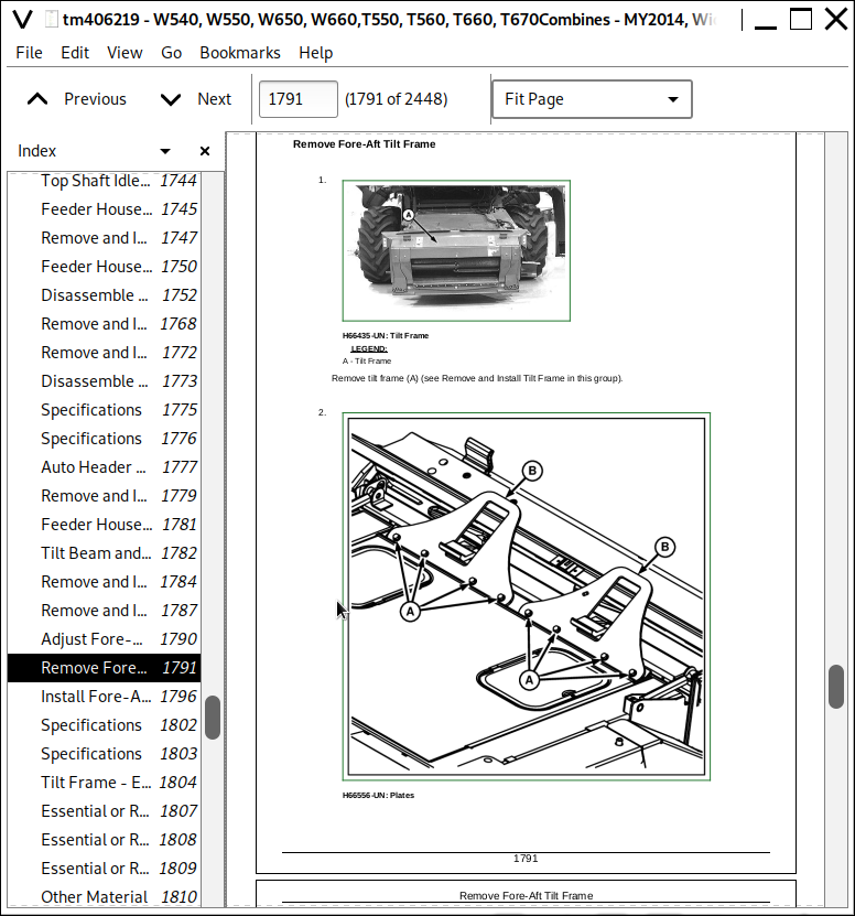
Remove Fore-Aft Tilt Frame
Install Fore-Aft Tilt Frame
Group 25: HillMaster™ II Tilt Cylinder and Frame
Specifications
Tilt Frame - Exploded View
Section 120: Separator, W-Series Combines
Group 05: Separator Repair
Essential or Recommended Tools
Other Material
Specifications
Remove and Install Rasp Bars
Static Balance Cylinder
Remove Threshing Cylinder
Install Threshing Cylinder
Remove Concave
Install Concave
Level Concave (Rasp Bar)
Level Concave (Spike Tooth)
Concave Position Sensor and Linkage
Remove and Install Concave Adjusting Motor
Beater, Exploded View
Disassemble and Assemble Beater
Remove and Install Beater
Group 06: Beater (T Series)
Specifications
Other Material
Remove and Install Beater
Remove Speed Sensor (Left Side)
Remove Locking Collar
Remove Beater Pulley (Right Side)
Remove Hub and Speed Sensor (Right Side)
Remove Beater Grate
Disassemble Beater
Install Beater Grate
Remove Bearing
Remove Shaft
Install Beater
Group 07: Separator Rotor/Separator Grate (T Series)
Specifications
Remove and Install Separator Rotor
Measure Distance from Pulley to Sidewall
Remove Pulley (Left Side)
Remove Pulley (Right Side)
Remove Hub
Remove Finger Bars and Retaining Plates
Loosen Segment Clamping Screws
Remove Bearings
Install Separator Rotor
Group 08: Separator Grate (T Series)
Specifications
Remove and Install Separator Grate
Remove Finger Bars of Separator Rotor
Remove Separator Grate Inserts
Position Separator Grate
Lift Out Separator Grate
Install and Adjust Separator Grate
Group 09: Overshot Beater/Stripper (T Series)
Specifications
Remove and Install Overshot Beater
Remove Pulley
Remove Gearcase
Disassemble Overshot Beater
Remove Locking Collar (Right Side)
Install Overshot Beater
Remove and Install Stripper
Remove Pulley
Remove Locking Collar (Right Side)
Remove stripper from the front
Stripper Roll, Exploded View
Install Stripper
Group 10: Cylinder Drives
Essential or Recommended Tools
Other Material
Specifications
Remove Cylinder Drive Sheave
Install Cylinder Drive Sheave
Remove Dual Range Cylinder Drive Gear Case
Install Dual Range Cylinder Drive Gear Case
Dual Range Cylinder Drive, Exploded View
Disassemble and Assemble Dual Range Cylinder Drive Gear Case
Remove and Install Intermediate Cylinder Drive
Repair Intermediate Cylinder Drive
Remove and Install Intermediate Cylinder Drive Support
Disassemble and Assemble Intermediate Cylinder Drive Upper Sheave
Group 15: Walkers, Walker Shafts and Walker Return Pan
Essential or Recommended Tools
Other Material
Specifications
All Walkers - Timing Procedure
Remove and Install Straw Walker Bearings and Walker Return Pan
Remove and Install Rear Walker Shaft
Remove and Install Front Walker Shaft
Remove and Install Straw Walker Gear Case (W Series)
Remove Straw Walker Drive (T Series)
Disassemble and Assemble Straw Walker Gearcase
Remove and Install Power Separator
Group 20: Straw Chopper and Chaff Spreader
Service Equipment and Tools
Other Material
Specifications
Chopper Rotor
Chopper Housing and Knife Bank
Remove Straw Chopper
Replace Chopper Blades
Replace Knife Sections
Remove and Install Rotor Bearings
Remove and Install Chopper Idler Assembly
Remove and Install Straw Chopper Jackshaft
Disassemble and Assemble Straw Chopper Jackshaft
Remove and Install Straw Chopper Idler Assembly
Remove and Install Chaff Spreader
Group 25: Shoe Supply Augers, Cleaning Fan, Chaffer/Sieve Frame
Other Material
Specifications
Replace Shoe Supply Augers
Replace Shoe Supply Auger Wooden Bearings
Remove and Install Shoe Supply Auger Drive Shaft
Remove and Install Shoe Supply Auger Trough
Remove Separator Drive Jackshaft
Install Separator Drive Jackshaft
Remove and Install Cleaning Fan Drive
Fan Drive Speed Control
Remove Cleaning Fan
Install Cleaning Fan
Remove and Install Cleaning Fan Housing
Adjust Fan Speed Actuator
Remove Chaffer, Sieve and Frames
Install Chaffer, Sieve and Frames
Remove and Install Shoe Pitman Arms
Group 30: Tailings Elevator and Augers
Disassemble Tailings Elevator and Augers
Group 31: Tailings Elevator and Auger Slip Clutch (T Series)
Park Machine Safely
Remove Slip Clutch for Tailings Elevator and Auger
Disassemble Slip Clutch
Install Brass Disk and Assemble Slip Clutch
Install Slip Clutch and Tension Drive Belts
Group 35: Primary Countershaft
Essential or Recommended Tools
Specifications
Remove and Install Primary Countershaft Gear Case
Disassemble and Assemble Primary Countershaft Gear Case - Type A
Primary Countershaft Gear Case - Type B
Remove and Install Primary Countershaft with Variable Sheave Assembly
Remove and Install Beater Curtain
Group 40: Header Electromagnetic Clutch
Specifications
Remove Header Electromagnetic Clutch
Disassemble and Assemble Header Electromagnetic Clutch
Install Header Electromagnetic Clutch
Section 130: Grain Tank and Unloading System
Group 05: Grain Tank Cross Augers
Remove and Install Grain Tank Cross Augers
Group 10: Auger System Drives
Specifications
Replace Unloading Auger Drive Belts
Remove and Install Cross Auger Countershaft Hub and Shear Bolt
Remove Unloading Auger Drive Countershaft
Install Unloading Auger Drive Countershaft
Align Unloading Auger Drive
Adjust Unloading Auger Drive Cylinder
Replace Unloading Auger Grain Saver Door
Group 15: Vertical Auger and Lower Gear Case
Essential or Recommended Tools
Specifications
Remove Vertical Auger Lower Gear Case And Vertical Auger
Disassemble and Assemble Vertical Auger Lower Gear Case
Install Vertical Auger and Vertical Auger Lower Gear Case
Group 20: Horizontal Auger and Gear Case
Essential or Recommended Tools
Other Material
Specifications
Inspection of Horizontal Unloading Auger
17 ft. (5.18 m) and 20 ft. (6.1 m) Augers - Two-Piece
Remove Horizontal Auger
Install Horizontal Auger
Remove Horizontal Auger Gear Case
Disassemble And Assemble Horizontal Unloading Auger Gear Case
Install Horizontal Auger Gear Case
Remove Horizontal Unloading Auger Tube
Folding Horizontal Auger Pivot Exploded View
Remove and Install Folding Auger Actuator
Unloading Auger Elbow, Exploded View
Remove Horizontal Unloading Auger Elbow
Install Horizontal Unloading Auger Elbow
Remove Unloading Auger Charge Housing
Group 25: Clean Grain Elevator and Loading Auger Gear Case
Other Material
Specifications
Adjust Clean Grain Elevator Chain
Replace Clean Grain Elevator Belt
Clean Grain Loading Auger, Exploded View
Replace Clean Grain Loading Auger Bearing
Remove Clean Grain Loading Auger Assembly
Remove and Install Clean Grain Elevator Gear Case
Disassemble and Assemble Clean Grain Elevator Gear Case
Remove Clean Grain Elevator
Group 30: Grain Tank and Extensions
Grain Tank Base
Grain Tank
Grain Tank Covers - 8,000 and 9,000 Liters
Grain Tank Cover Seals - 8,000 and 9,000 Liters
Grain Tank Cover Supports - 8,000 and 9,000 Liters
Grain Tank Cover Cylinders - 8,000 and 9,000 Liters
Grain Tank Cover Actuator - 8,000 and 9,000 Liters
Grain Tank, General View - 11,000 Liters
Grain Tank Covers - 11,000 Liters
Grain Tank Lift Cylinders and Linkage - 11,000 Liters
Section 140: Engine Gear Case and Control Valve
Group 05: Engine Gear Case and Valve
Essential or Recommended Tools
Other Material
Specifications
General Information
Remove and Install Engine Gear Case
Engine Gear Case Specifications
Disassemble and Assemble Separator Drive Wet Clutch
Disassemble and Assemble Hydrostatic Gear Set
Set Hydrostatic Gearset Position
Preload Hydrostatic Gearset Bearings
Disassemble and Assemble Straw Chopper and Unloading Auger Drive
Set Separator Gearset Position
Preload Separator Gearset Bearings
Disassemble and Assemble Separator Drive
Preload Separator Drive Bearings
Set Separator Drive Gear Backlash
Disassemble and Assemble Hydrostatic Pump Drive
Preload Hydrostatic Pump Drive Bearings
Set Hydrostatic Pump Drive Gear Backlash
Disassemble and Assemble Oil Screen
Disassemble and Assemble Oil Trough
Disassemble and Assemble Dipstick Tube
Remove and Install Filter
Remove and Install Pressure Regulating Valve
Disassemble and Assemble Pressure Regulating Valve
Section 199: Special Tools
Group 05: Essential Special Tools
Tools (Section 20)
Tools (Section 40)
Tools (Section 50)
Tools (Section 60)
Tools (Section 70)
Tools (Section 90)
Tools (Section 120)
Tools (Section 130)
Tools (Section 140)
Group 10: Recommended Special Tools
DFRW20—Compressor Holding Fixture
Adapter for Straw Walker Crankshaft
Cooling Fin Straightener
Special Tool for Disassembling Valve Seat and Piston
Special Tool for Positioning Swash Plate
John Deere W540, W550, W650, W660, T550, T560, T660, T670 Combines (MY14) Repair Service Manual (TM406219)
![]()