
John Deere Sugar Cane Harvester 3520, 3522 Repair Service Manual (TM100419)

John Deere Sugar Cane Harvester 3520, 3522 Repair Service Manual (TM100419)
TM100419 - John Deere Sugar Cane Harvester 3520, 3522 Technical Manual (Repair).PDF
Complete Repair manual for John Deere 3520, 3522 Sugar Cane Harvesters PIN Prefix NW, with all the service information to maintain, diagnostic, repair, rebuild like professional mechanics.
John Deere Track & Wheel Sugar Cane Harvesters 3520, 3522 workshop Repair manual includes:
* Numbered table of contents easy to use so that you can find the information you need fast.
* Detailed sub-steps expand on repair procedure information
* Numbered instructions guide you through every repair procedure step by step.
* Notes, cautions and warnings throughout each chapter pinpoint critical information.
* Bold figure number help you quickly match illustrations with instructions.
* Detailed illustrations, drawings and photos guide you through every procedure.
* Enlarged inset helps you identify and examine parts in detail.
Total Pages: 2,340 pages
File Format: PDF (bookmarked, ToC, Searchable, Printable, high quality)
Language: English
MAIN SECTIONS
Foreword
General
Safety
General Specifications
Fuels and Lubricants
Tune-Up and Adjustments
Engine
Component Removal and Installation
Cooling System
Exhaust System
Auxiliary Coolers
Fuel and Air
Diesel Fuel System
Air Intake System
Electrical
Batteries
Electrical Harness and Connectors
Wire Harness Routings
Sensors and Switches
Lighting
Fuses and Relays
Operator Station
Charging System
Starting System
Power Train
Pump Drive
Hydrostatic Drive Pumps
Hydrostatic Drive Motors
Final Drive Repair
Track
Ground Conditions
Operating Conditions
Undercarriage Wear
Glossary
Track Repair
Wheel
Wheel
Steering and Brakes
Steering Column
Steering Valve and Control Unit
Steering Arms and Pivots
Brakes
Hydraulic System
Hydraulic Reservoir
Hydraulic Pumps
Hydraulic Valves
Hydraulic Cylinders
Hydraulic Motors
Accumulators
Miscellaneous
Handrails and Platform
Shields and Doors
Operator Station
Air Conditioning System
System Components
Seats
Cab
Topper System
Topper
Crop Divider System
Crop Divider
Knockdown Rollers
Knockdown Rollers
Base Cutter System
Base Cutter
Feed Roller System
Rollers
Chopper System
Chopper
Cleaning System
Primary Extractor
Secondary Extractor
Elevator System
Elevator
Dealer Fabricated Tools
Dealer Fabricated Tools
tm100419 - 3520 and 3522 Sugar Cane Harvester Repair Manual
Table of Contents
Foreword
Section 10: General
Group 05: Safety
Recognize Safety Information
Understand Signal Words
Follow Safety Instructions
Work in Clean Area
Service Machines Safely
Emergency Exit
Work In Ventilated Area
Illuminate Work Area Safely
Replace Safety Signs
Use Proper Lifting Equipment
Support Machine Properly
Avoid Heating Near Pressurized Fluid Lines
Handle Fluids Safely—Avoid Fires
Remove Paint Before Welding or Heating
Precautions for Welding
Live With Safety
Avoid Harmful Asbestos Dust
Practice Safe Maintenance
Use Proper Tools
Construct Dealer-Made Tools Safely
Seat Safety Switch
Tilting the Cab
Protect Bystanders
Use Steps and Handholds Correctly
Wear Protective Clothing
Handle Fuel Safely—Avoid Fires
Avoid Static Electricity Risk When Refueling
Service Accumulator Systems Safely
Service Cooling System Safely
Prepare for Emergencies
Use Safety Lights and Devices
Using Cylinder Safety Stops
Safe Transport of Harvester
Avoid High-Pressure Fluids
Wait Before Opening High-Pressure Fuel System
Use Caution on Hillsides
Use Caution On Slopes When Turning
Stopping and Parking
Park Machine Safely
Service Tires Safely
Service Tires Safely
Avoid Electrical Power Lines
Keep Hands Away from Knives
Decommissioning: Proper Recycling and Disposal of Fluids and Components
Prevent Battery Explosions
Handling Batteries Safely
Fire Prevention
In Case of Fire
Servicing Electronic Control Units
Welding Near Electronic Control Units
Keep Electronic Control Unit Connectors Clean
Stay Clear of Harvesting Units
Stay Clear of Rotating Drivelines
Keep Riders and Children Off Machine
Instructional Seat
Install All Guards
Avoid Hot Exhaust
Group 10: General Specifications
Dimensions
Weight
Component Specifications
Engine Specifications
Capacities
Travel Speeds
Interpreting Machine Serial Number
Machine Serial Number
Engine Serial Number
Pump Drive Gear Case Serial Number
Critical Torque Specifications
Identifying Zinc-Flake Coated Fasteners
Unified Inch Bolt and Screw Torque Values
Metric Bolt and Screw Torque Values
Face Seal Fittings Assembly and Installation—All Pressure Applications
Metric Face Seal and O-Ring Stud End Fitting Torque Chart—Standard Pressures
Metric Face Seal and O-Ring Stud End Fitting Torque Chart—High Pressure Applications
SAE Face Seal and O-Ring Stud End Fitting Torque Chart—Standard Pressures
SAE Face Seal and O-Ring Stud End Fitting Torque Chart—High Pressure Applications
Four Bolt Flange Fittings Assembly and Installation—All Pressure Applications
SAE Four Bolt Flange Cap Screw Torque Values—Standard Pressure Applications
SAE Four Bolt Flange Cap Screw Torque Values—High Pressure Applications
Sealants and Adhesives Cross-Reference Chart
Group 15: Fuels and Lubricants
Lubricate Machine Properly
Diesel Engine Break-In Oil — Non-Emissions Certified and Certified Tier 1, Tier 2, Tier 3, Stage I, Stage II, and Stage III
Diesel Engine Oil — Tier 2 and Stage II
Diesel Engine Oil — Tier 3 and Stage III
Diesel Fuel
Lubricity of Diesel Fuel
Diesel Engine Coolant
Diesel Engine Coolant (engine with wet sleeve cylinder liners)
John Deere COOL-GARD™ II Coolant Extender
Additional Information About Diesel Engine Coolants and John Deere COOL-GARD™ II Coolant Extender
Operating in Warm Temperature Climates
Supplemental Coolant Additives
Testing Diesel Engine Coolant
Pump Drive, Base Cutter, and Chopper Gear Case Oil
Hydraulic Oil
Final Drive Gear Oil
Grease
Alternative and Synthetic Lubricants
Group 20: Tune-Up and Adjustments
Tune-Up and Adjustment
Check Oil Lines And Fittings
Basic Electrical Component Handling / Precautions For Vehicles Equipped With Computer Controlled Systems
Programming Control Units
Section 20: Engine
Group 05: Component Removal and Installation
Special Tools
Other Material
Specifications
John Deere Engine Repair—Use CTM
Remove and Install Engine
Remove and Install Serpentine Belt
Inspect Belt Tensioner
Replace Engine Isolators
Group 10: Cooling System
Special Tools
Other Material
Specifications
Test Surge Tank Cap
Test Radiator and Surge Tank
Remove and Install Radiator
Drain, Flush, and Fill Cooling System
Remove and Install Fan
Thermostat Repair—Use CTM
Engine Water Pump Repair—Use CTM
Group 15: Exhaust System
Remove and Install Muffler
Group 20: Auxiliary Coolers
Specifications
Remove and Install Air Conditioning Condenser-Fuel Cooler
Remove and Install Hydraulic Oil Cooler
Remove and Install Charge Air Cooler
Cleaning Charge Air Cooler
Section 30: Fuel and Air
Group 05: Diesel Fuel System
Other Material
John Deere Fuel System Repair—Use CTM
Remove and Install Fuel Filters
Bleed Fuel System—Use CTM
Remove and Install Fuel Tank
Remove and Install Fuel Cooler
Group 10: Air Intake System
Remove and Install Engine Air Filters
Clean and Inspect Primary Air Filter
Remove and Install Air Cleaner Inlet Assembly
Turbocharger Repair—Use CTM
Section 40: Electrical
Group 05: Batteries
Specifications
Servicing Battery
Checking Battery Fluid Level
Preventing Battery Damage
Charging Battery
Battery Disconnect Switch
Remove and Install Batteries
Group 10: Electrical Harness and Connectors
Use Electrical Insulating Compound
Electrical System Visual Inspection
Using High-Pressure Washers
Basic Electrical Component Handling / Precautions for Vehicles Equipped with Computer Controlled Systems
Electrical Connector / Wiring Harness Handling and Repair
Repair Procedure R-A
Repair Procedure R-B
Repair Procedure R-C
Repair Procedure R-D
Repair Procedure R-E
Repair Procedure R-F
Repair Procedure R-G
Repair Procedure R-I
Repair Procedure R-J
Repair Procedure R-K
Repair Procedure R-M
Repair Procedure R-N
Harness Repair — Splice Connector
Group 15: Wire Harness Routings
Cab Harness Routing
Armrest Harness Routing
Front Chassis Harness Routing
Engine Harness Routing
Battery Harness Routing
Rear Chassis Harness Routing
Main Track Harness Routing
Elevator Harness Routing
Group 20: Sensors and Switches
Other Material
Specifications
Replace Engine Sensors and Switches—Use CTM
Remove and Install Engine Access Door Switch
Remove and Install Fuel Level Sensor
Remove and Install Hydraulic Oil Temperature Sensor
Remove and Install Hydraulic Reservoir Level Switch
Remove and Install Hydraulic Reservoir Pressure Switch
Remove and Install Crop Divider Position Sensor (If Equipped)
Remove and Install Base Cutter Position Sensor (Wheel Harvester)
Remove and Install Base Cutter Position Sensor (Track Harvester)
Remove and Install Base Cutter Motor Pressure Sensor
Remove and Install Chopper/Base Cutter Pump Pressure Sensor
Steering Input Device (SID) (Track Harvester)
Remove and Install Primary Extractor Fan Speed Sensor
Remove and Install Air Filter Restriction Switch
Remove and Install Hydrostatic Drive Motor Speed Sensor—Single Speed (Track Harvester)
Remove and Install Hydrostatic Drive Motor Speed Sensor—Two-Speed (Track Harvester)
Remove and Install Hydrostatic Drive Motor Speed Sensor (Wheel Harvester)
Remove and Install Park Brake Valve Pressure Sensor
Group 25: Lighting
Remove and Install Cab Dome Light Assembly
Remove and Install Tail Lights
Remove and Install Engine Compartment Work Light
Remove and Install Front Turn Signals
Remove and Install Side Lights
Remove and Install Elevator Lights
Remove and Install Cab Roof Lights
Group 30: Fuses and Relays
Replacing Fuses
Fuse and Relay Panel Location
Fuse and Relay Identification
Group 35: Operator Station
Special Tools
Other Material
Specifications
Remove and Install Wiper Motor
Armrest Console Controls
Remove and Install CommandTouch™ Console
Remove and Install Multi-Function Lever
Remove And Install Multi-Function Lever Position Sensor
Replace Neutral Safety Switch
Overhead Console Control Identification
Remove and Install Overhead Console Switches
Remove and Install Radio
Remove and Install Radio Speaker
Floor Pedal Identification
Remove and Install Floor Pedals
Remove and Install Key Switch
Remove and Install Turn Signal Switch
Remove and Install CommandCenter™ (VTI) Display Unit
Replace Primary Display Unit (PDU)
Group 40: Charging System
Special Tools
Other Material
Specifications
Remove and Install Alternator
Remove and Install Alternator Pulley
John Deere Engine Accessories—Alternator Repair
Group 45: Starting System
Special Tools
Other Material
Specifications
Remove and Install Starting Motor
John Deere Starting Motor Repair
Section 50: Power Train
Group 05: Pump Drive
Special Tools
Other Material
Specifications
Remove and Install Pump Drive Gear Case
Remove and Install Drive Coupling Assembly
John Deere Pump Drive Gear Case Repair—Use CTM
Group 10: Hydrostatic Drive Pumps
Special Tools
Other Material
Specifications
Remove and Install Hydrostatic Drive Pumps
Hydrostatic Drive Pump Exploded View
Remove and Install Hydrostatic Drive Pump Shaft Seal
Remove and Install Hydrostatic Drive Pump Multi-Function Cartridge Valves
Engage and Disengage Drive Pump Bypass Actuators
Remove and Install Hydrostatic Drive Pump Charge Pressure Relief Valve
Repair Charge Pump
Remove and Install Hydrostatic Drive Pump Electronic Displacement Control
Remove and Install Pressure Control Pilot
Disassemble and Assemble Hydrostatic Drive Pump
Hydraulic-Hydrostatic System Flushing Procedure
Start-up Procedure After Hydrostatic Repair
Group 15: Hydrostatic Drive Motors
Special Tools
Other Material
Specifications
Remove and Install Hydrostatic Drive Motor (Wheel Harvester)
Remove and Install Hydrostatic Motor (Track Harvester)
Hydrostatic Drive Motor—Single Speed (Style A) Exploded View
Remove and Install Hydrostatic Drive Motor Shaft Seal—Single Speed (Style A)
Disassemble and Assemble Hydrostatic Drive Motor—Single Speed (Style A)
Remove and Install Hydrostatic Drive Motor Shaft Seal—Single Speed (Style B)
Remove and Install Hydrostatic Drive Motor End Cover O-Ring—Single Speed (Style B)
Remove and Install Hydrostatic Drive Motor Flushing Valve—Single Speed (Style B)
Disassemble and Assemble Hydrostatic Drive Motor—Two-Speed (Style A)
Disassemble and Assemble Hydrostatic Drive Motor—Two-Speed (Style B)
Disassemble and Assemble Hydrostatic Drive Motor Port Plate—Two-Speed
Group 20: Final Drive Repair
Special Tools
Other Material
Specifications
Remove and Install Final Drive (Wheel Harvester)
Remove and Install Final Drive (Track Harvester)
Final Drive Exploded View (S.N. 120701— )
Disassemble Final Drive (S.N. 120701— )
Assemble Final Drive (S.N. 120701— )
Final Drive Exploded View (S.N. —100986)
Disassemble Final Drive (S.N. —100986)
Assemble Final Drive (S.N. —100986)
Section 55: Track
Group 05: Ground Conditions
Ground Conditions
Abrasion
Impact
Packing
Moisture
Temperature
Chemicals
Group 10: Operating Conditions
Operating Conditions
Avoid Impacts When Possible
Do Not Spin Tracks
Avoid Excessive Speed
Avoid Unnecessary Reverse Operation
Use Counter-Rotation Wisely
Store the Machine Properly
Use Proper Maintenance Procedures
Keep Good Undercarriage Records
Track Bouncing
Sprocket Ratchet
Vibration
Pin and Bushing Retention Life
Sealed and Lubricated Track Chain Pin and Bushing Joint Life
Group 15: Undercarriage Wear
Link Rail Surface Wear
Link Rail Top Wear Uneven (Scalloped)
Link Roll-Over
Link Face Wear
Rail Side Wear
Pin Boss Wear
Link Counterbore Wear
Link Cracking
Rail Chipping
Track Link Wear Measurement
Internal Wear
Pin Breakage
Master Pin and Bushing Wear
Pin End Wear
Forward Drive Side Contact
Reverse Drive Side Contact
Pitch Wear
Forward Drive Side Tooth Wear
Forward Drive Side Bushing Wear
Reverse Operation
Reverse Drive Side Tooth Wear
Reverse Drive Side Bushing Wear
Bushing Cracks
Sprocket Root Wear
Bushing Radial Wear
Reverse Drive Side Tip Wear
Back Jamming
Forward Drive Side Tip Wear
Sprocket Side Wear
Tooth Corner Breakage
Tooth Tip Breakage
Sprocket Mounting
Sprocket Identification
Bushing and Link Counterbore Wear
Bushing End Cracks
Bushing End Wear
Bushing Seal Face—Sealed and Lubricated Track Chain
Track Link Bushing Wear Measurement
Roller Tread Wear
Roller Flange Top Wear
Roller Flat Spots
Roller Flange Side Wear
Track Roller Wear Measurement
Idler Tread Wear
Idler Tread Cracks
Idler Flange Side Wear
Idler Flange Top Wear
Idler Sidewall Wear and Cracking
Idler Wear Measurement
Carrier Roller Tread Wear
Carrier Roller Flange Wear
Carrier Roller Flange Top Wear
Carrier Roller Wear Measurement
Grouser Wear
Shoe Bending
Leading and Trailing Edge Wear
Shoe Contact with Rock Guard
Loose Hardware Damage
Track Shoe Wear Measurement
Track Guide Wear
Group 20: Glossary
Undercarriage
Carrier Roller
Front Idler
Ground Conditions
Grouser
Link
Sealed and Lubricated Track Chain
Master Bushing
Master Track Shoe
Sealed Track Chain
Pin Boss
Basecutter Guards
Track Guides
Sprocket
Track Adjuster
Track Bushing
Track Frame
Track Chain Pin
Track Roller
Track Seals—Sealed and Lubricated Track Chain
Track Shoes
Group 25: Track Repair
Special Tools
Other Material
Specifications
Adjust Track Chain Tension
Remove and Install Track Shoe
Remove and Install Track Assembly
Remove and Install Axle
Remove and Install Track Chain
Remove and Install Tension Idler
Remove and Install Track Idler
Remove and Install Track Sprocket
Remove and Install Track Rollers
Remove and Install Track Guides
Disassemble, Inspect, Lubricate, and Assemble Track Chain
Section 57: Wheel
Group 05: Wheel
Other Material
Specifications
Jack Locations
Remove and Install Wheel Assembly
Remove and Install Front Wheel Bearings
Remove and Install Tire
Section 60: Steering and Brakes
Group 05: Steering Column
Specifications
Steering Column Components (Style A)
Steering Column Components (Style B)
Disassemble And Assemble Steering Column (Style B)
Replace Telescoping Shaft Bearings
Group 10: Steering Valve and Control Unit
Other Material
Specifications
Remove and Install Steering Valve (Wheel Harvester)
Steering Valve Exploded View (Wheel Harvester)
Disassemble and Assemble Steering Valve (Wheel Harvester)
Remove and Install Steering Control Unit (Track Harvester)
Remove and Install Steering Input Device (SID) (Track Harvesters)
Group 15: Steering Arms and Pivots
Specifications
Steering Linkage Exploded View
Check and Adjust Front Wheel Toe-In
Group 20: Brakes
Park Brake Repair
Section 70: Hydraulic System
Group 05: Hydraulic Reservoir
Other Material
Specifications
Drain and Fill Hydraulic Reservoir
Replace Hydraulic Reservoir Sight Gauge Assembly
Remove and Install Hydraulic Filter Assemblies
Remove and Install Hydraulic Reservoir
Connecting Vacuum Pump to Hydraulic Reservoir
Group 10: Hydraulic Pumps
Special Tools
Other Material
Specifications
Pump Identification
Base Cutter and Chopper Pumps Exploded View
Remove and Install Base Cutter Pump (Optional)
Remove and Install Chopper/Base Cutter Pump
Remove and Install Primary Extractor Pump
Remove and Install Multi-Function Gear Pump
Remove and Install Feed System Gear Pump
Remove and Install Base Cutter and Chopper Pump Electronic Control
Disassemble and Assemble Base Cutter and Chopper Pumps
Remove and Install Primary Extractor Pump Electronic Displacement Control
Disassemble and Assemble Primary Extractor Pump
Multi-Function Gear Pump Exploded View
Feed System Gear Pump Exploded View
Repair Multiple Gear Pumps
Remove and Install Cab Tilt Hand Pump
Fill and Bleed Cab Tilt Hand Pump
Start-Up Procedure After Hydraulic Pump Repair
Group 15: Hydraulic Valves
Other Material
Specifications
Remove and Install Topper Valve
Disassemble and Assemble Topper Valve
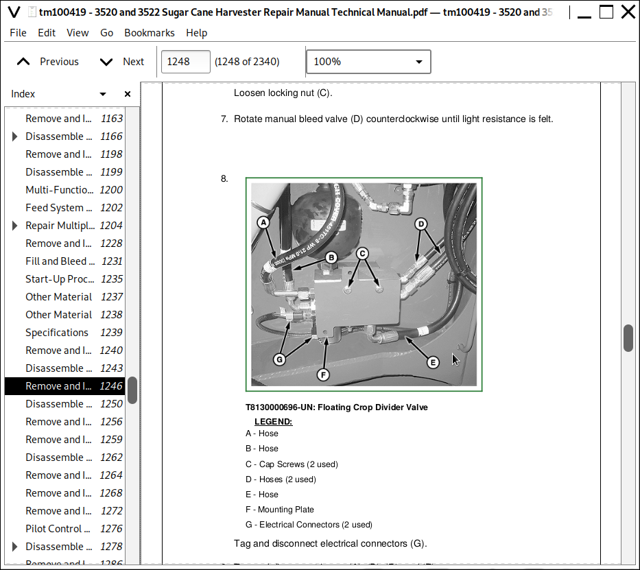
Remove and Install Floating Crop Divider Valves
Disassemble and Assemble Floating Crop Divider Valve
Remove and Install Improved Height Control Valve
Remove and Install Suspension Control Valve (Track Harvester)
Disassemble and Assemble Suspension Control Valve (Track Harvester)
Remove and Install Front Feed Pilot Control Valve
Remove and Install Front Feed Pilot Control Valve (Optional Valve)
Remove and Install Rear Feed Pilot Control Valve
Pilot Control Valve Exploded View
Disassemble and Assemble Front Feed, Front Feed (Optional Valve), and Rear Feed Pilot Control Valves
Remove and Install Feed System Solenoid Valve
Remove and Install Flow Divider Valve
Disassemble and Assemble Flow Divider Valve
Remove and Install Steering Priority Valve (Wheel Harvester)
Disassemble and Assemble Steering Priority Valve (Wheel Harvester)
Remove and Install Chopper Curtain Agitator Valve
Remove and Install Cooling System Reversible Motor Valve
Disassemble and Assemble Cooling System Reversible Motor Valve
Remove and Install Swing Table Holding Valve
Remove and Install Elevator Speed Control Valve
Disassemble and Assemble Billet Length and Elevator Speed Control Valves (Manual Adjust)
Remove and Install Triple Relief Valve
Disassemble and Assemble Triple Relief Valve
Remove and Install Elevator Valve
Disassemble and Assemble Elevator Valve
Remove and Install Cylinder Function Valve (6 Bank)
Disassemble and Assemble Cylinder Function Valve (6 Bank)
Remove and Install Auxiliary Tilt Function Valve (4 Bank)
Remove and Install Park Brake Valve
Disassemble and Assemble Park Brake Valve
Remove and Install Remote Flushing Valve
Remove and Install Varitorq Valve (Wheel Harvester)
Remove and Install Ground Drive High/Low Valve (Track Harvester)
Remove and Install Positive Traction Valve (Wheel Harvester)
Group 20: Hydraulic Cylinders
Other Material
Specifications
Test Double Action Cylinders
Remove and Install Topper Cylinder
Remove and Install Cab Tilt Cylinder
Remove and Install Elevator Swing Cylinders
Disassemble and Assemble Topper, Cab Tilt, and Elevator Swing Cylinders—Use CTM
Remove and Install Steering Cylinders (Wheel Harvester)
Disassemble and Assemble Steering Cylinders (Wheel Harvester)
Remove and Install Crop Divider Lift Cylinders
Disassemble and Assemble Crop Divider Lift Cylinders
Remove and Install Base Cutter Lift Cylinders (Wheel Harvester)
Disassemble and Assemble Base Cutter Lift Cylinders (Wheel Harvester)
Remove and Install Base Cutter Lift Cylinders (Track Harvester)
Disassemble and Assemble Base Cutter Lift Cylinders (Track Harvester)
Remove and Install Knockdown Tilt Cylinder (Optional)
Remove and Install Crop Divider Tilt Cylinders (Optional)
Disassemble and Assemble Knockdown Tilt and Crop Divider Tilt Cylinder (Optional)
Remove and Install Elevator Lift Cylinders
Disassemble and Assemble Elevator Lift Cylinders
Remove and Install Elevator Discharge Flap Cylinder
Disassemble and Assemble Elevator Discharge Flap Cylinder
Group 25: Hydraulic Motors
Special Tools
Other Material
Specifications
Remove and Install Topper Gathering Disk Motor (Whole Topper)
Remove and Install Topper Gathering Disk Motor (Shredder Topper)
Remove and Install Topper Severing Disk Motor (Whole Topper)
Remove and Install Topper Drum Motor (Shredder Topper)
Topper Severing Disk (Whole Topper) and Secondary Extractor Fan Motors Exploded View
Disassemble and Assemble Topper Severing Disk (Whole Topper) and Secondary Extractor Fan Motors
Remove and Install Crop Divider Scroll Motor
Remove and Install Outer Scroll Motor
Remove and Install Side Knife Motor
Remove and Install Crop Divider Knockdown Roller Motor
Remove and Install Adjustable Knockdown Roller Motor
Remove and Install Fixed Knockdown Roller Motor
Remove and Install Base Cutter Motor
Remove and Install Feed Roller Motors
Remove and Install Butt-Lifter Roller Motors
Disassemble and Assemble Topper Gathering Disk, Scroll, Side Knife, Crop Divider Knockdown Roller, Fixed and Adjustable Knockdown Rollers, Butt-Lifter, Feed Roller, Sill Roller, and Elevator Motors
Remove and Install Chopper Motor
Chopper Motor Exploded View
Disassemble and Assemble Chopper Motor
Base Cutter and Primary Extractor Fan Motors Exploded View
Disassemble and Assemble Base Cutter and Primary Extractor Fan Motors
Remove and Install Primary Extractor Fan Motor
Remove and Install Primary Extractor Swing Motor
Remove and Install Secondary Extractor Fan Motor
Remove and Install Secondary Extractor Rotate Motor
Remove and Install Chopper Curtain Agitator Motor
Remove and Install Sill Motor
Primary Extractor Swing, Secondary Extractor Rotate, and Chopper Curtain Agitator Motors Exploded View
Disassemble and Assemble Primary Extractor Swing, Secondary Extractor Rotate, and Chopper Curtain Agitator Motors
Remove and Install Elevator Motor
Remove and Install Cooling System Motor
Cooling System Motor Exploded View
Disassemble and Assemble Cooling System Motor
Group 30: Accumulators
Special Tools
Specifications
Charge Crop Divider and Base Cutter Accumulators
Charge Topper and Elevator Accumulators
Section 80: Miscellaneous
Group 05: Handrails and Platform
Specifications
Remove and Install Left-Hand Ladder
Remove and Install Right-Hand Ladder
Remove and Install Handrail System
Remove and Install Left-Hand Platform
Remove and Install Right-Hand Platform
Remove and Install Center Platform
Remove and Install Cab Brush Guard
Group 10: Shields and Doors
Remove and Install Engine Compartment Doors
Remove and Install Base Cutter Shields (Wheel Harvester)
Section 90: Operator Station
Group 05: Air Conditioning System
Special Tools
Other Material
Specifications
Service Parts Kits
Service Information
Hose and Tubing O-Ring Connection Torques
Proper Refrigerant Handling
R-134a Refrigerant Precautions
Leak Test With Dye
Flush Air Conditioning System
Purge Air Conditioning System
Evacuate Air Conditioning System
Charge Air Conditioning System
Check Refrigerant Oil Charge
Compressor Oil Information
Determine Correct Oil Charge
Replace Compressor Relief Valve
Remove and Install Compressor
Repair Compressor
Repair Compressor Clutch
Check Clutch Hub Clearance
Inspect Compressor Manifold
Test Shaft Seal Leakage
Test Volumetric Efficiency
Discharge and Recover Air Conditioning System
Group 10: System Components
Specifications
Remove and Install Blower Motor
Replace Receiver Dryer
Remove and Install Condenser
Repair Condenser
Replace Low Pressure Switch
Replace High Pressure Switch
Replace Expansion Valve
Group 15: Seats
Remove and Install Operator Seat
Remove and Install Operator Seat Presence Switch
Operator Seat Exploded View
Operator Seat Air Suspension Assembly Exploded View
Disassemble and Assemble Operator Seat Air Suspension Assembly
Remove and Install Instructional Seat
Group 20: Cab
Special Tools
Specifications
Remove and Install Cab Windshield
Remove and Install Rear Window
Remove and Install Side Window
Remove and Install Cab Outer Roof
Remove and Install Cab Inner Roof
Remove and Install Front Cab Headliner
Remove and Install Rear Cab Headliner
Remove and Install Cab Door
Disassemble and Assemble Cab Door
Cab Door Latch Striker
Cab Tilt Procedure
Remove and Install Cab
Section 100: Topper System
Group 05: Topper
Special Tools
Other Material
Specifications
Replace Topper Blades
Remove and Install Topper Gathering Disk (Whole Topper)
Remove and Install Topper Gathering Disk Extensions (Whole Topper)
Remove and Install Topper Severing Disk, Hub, and Drum (Whole Topper)
Remove and Install Topper Assembly
Remove and Install Topper Boom Arms
Shredder Topper Exploded View
Adjust Shredder Topper Shear Plates
Remove and Install Topper Gathering Disk (Shredder Topper)
Disassemble and Assemble Shredder Topper
Section 110: Crop Divider System
Group 05: Crop Divider
Special Tools
Other Material
Specifications
Remove and Install Crop Divider Assembly
Remove and Install Crop Divider Scroll and Bearing Assembly
Remove and Install Outer Scrolls
Remove and Install Outer Scroll Upper Brackets
Replace Outer Scroll Bearing Assembly
Remove and Install Floating Shoes
Replace Side Knife Blades
Remove and Install Side Knife Assembly
Remove and Install Vine Cutter Knives
Remove and Install Crop Divider Knockdown Roller Assembly
Gauge Wheel Exploded View (If Equipped)
Section 120: Knockdown Rollers
Group 05: Knockdown Rollers
Special Tools
Other Material
Specifications
Remove and Install Fixed Knockdown Roller Assembly
Disassemble and Assemble Fixed Knockdown Roller
Remove and Install Adjustable Knockdown Roller Assembly
Disassemble and Assemble Adjustable Knockdown Roller Assembly
Section 130: Base Cutter System
Group 05: Base Cutter
Special Tools
Other Material
Specifications
Base Cutter Gear Case Exploded View—3520
Base Cutter Gear Case Exploded View—3522
Remove, Service, and Install Base Cutter Blades
Remove and Install Base Cutter Disks
Repair Base Cutter Breakaway Legs (Optional)
Remove and Install Base Cutter Assembly (Wheel Harvester)
Remove and Install Base Cutter Assembly (Track Harvester)
Disassemble and Assemble Base Cutter Gear Case
Section 140: Feed Roller System
Group 05: Rollers
Special Tools
Other Material
Specifications
Feed Roller Identification
Remove and Install Butt-Lifter Roller (B1)
Remove and Install Bottom Feed Rollers (B2, B3, B4, and B5)
Remove and Install Top Feed Rollers (T1, T2, T3, T4, and T5)
Check and Adjust Feed Motor Mount Axial Alignment
Remove and Install Sill Roller Assembly
Section 150: Chopper System
Group 05: Chopper
Special Tools
Other Material
Specifications
Chopper Timing
Remove and Install Chopper Blades and Kicker Plates
Adjust Chopper Flywheel Clutch
Chopper Flywheel and Clutch Exploded View
Remove and Install Chopper Flywheel and Clutch
Remove and Install Left-Hand Chopper Bearings (Style A)
Remove and Install Left-Hand Chopper Bearings (Style B)
Remove and Install Chopper Assembly
Chopper Gear Case Exploded View
Disassemble and Assemble Chopper Gear Case
Remove and Install Chopper Curtain Agitator Assembly
Section 160: Cleaning System
Group 05: Primary Extractor
Other Material
Specifications
Adjust Primary Extractor Chain Tension
Remove and Install Primary Extractor
Remove and Install Primary Extractor Hood
Remove and Install Primary Extractor Fan
Start-up Procedure After Fan Installation
Group 10: Secondary Extractor
Special Tools
Other Material
Specifications
Remove and Install Secondary Extractor
Remove and Install Secondary Extractor Hood
Remove and Install Secondary Extractor Fan and Hub Assembly
Check and Adjust Secondary Extractor Fan Assembly Balance
Adjust Secondary Extractor Chain Tension
Section 170: Elevator System
Group 05: Elevator
Special Tools
Other Material
Specifications
Remove and Install Elevator
Remove and Install Elevator Chain
Check and Adjust Elevator Sprockets and Chain Tension
Remove and Install Elevator Chain Slats
Remove and Install Elevator Wear Strips
Replace Elevator Idler Sprocket Bearings
Replace Elevator Tail Shaft Bearing Assemblies
Remove and Install Tail Shaft
Remove and Install Elevator Swing Table
Remove and Install Elevator Discharge Flap
Elevator Bypass Procedure
Section 199: Dealer Fabricated Tools
Group 05: Dealer Fabricated Tools
DFRW20—Compressor Holding Fixture
DFEXT4—Sizing Arbor
DFT8T2—Bearing Stop Limit Driver
DFT8T3—Cab Lifting Bracket
DFT8T4—Front Wheel Removal and Installation Tool
DFT8T5—Rear Wheel Removal and Installation Tool
DFT8T6—Final Drive Cover Removal Tool
![]()