
John Deere Trailed Crop Sprayers Models 824, 832, 840 Diagnosis & Tests Service Manual (TM4782)

John Deere Trailed Crop Sprayers Models 824, 832, 840 Diagnosis & Tests Service Manual (TM4782)
TM4782 - John Deere Trailed Crop Sprayers Models 824, 832 and 840 with ELC-1/EHC-2/EL-4 Control Unit / with TwinFluid Spraying System Technical Service Manual (Diagnosis & Tests).PDF
Complete Diagnosis & Tests manual with Electrical Wiring Diagrams for John Deere Trailed Crop Sprayers Models 824, 832, 840, with all the shop information to maintain, diagnostic, repair, refurbish/rebuild like professional mechanics.
John Deere Trailed Crop Sprayers Models 824, 832, 840 workshop Operation & Test manual includes:
* Numbered table of contents easy to use so that you can find the information you need fast.
* Detailed sub-steps expand on repair procedure information
* Numbered instructions guide you through every repair procedure step by step.
* Troubleshooting and electrical service procedures are combined with detailed wiring diagrams for ease of use.
* Notes, cautions and warnings throughout each chapter pinpoint critical information.
* Bold figure number help you quickly match illustrations with instructions.
* Detailed illustrations, drawings and photos guide you through every procedure.
* Enlarged inset helps you identify and examine parts in detail.
Total Pages: 1,068 pages
File Format: PDF (bookmarked, ToC, Searchable, Printable, high quality)
Language: English
MAIN SECTIONS
Foreword
Safety
Safety Information
General Information
Description of the Machine
Torques for Hardware
Specifications
Electrical System
Connector Repair
Electrical Control
Troubleshooting (General)
Troubleshooting – EL4 Control Unit
Troubleshooting – ELC-1/EHC-2 Control Units
GreenStar™ Programming and Info
GreenStar™ Caution and Warning Statements
Power Train
Compressor
Gearbox
Brake System
Hydraulic Brake System
Pneumatic Brake System
Hydraulic System
Hydraulic Functions
Hydraulic Cylinders
Control Valves
Accumulator
Sensors
Adjustments
Hydraulic Diagrams
Miscellaneous
Welding and Repair
Function Diagrams
Sprayboom
Sprayboom Adjustments
Center Frame
Track Width Adjustment
Axle
Drawbar Adjustments
Drawbar
Parallelogram
Tank and Accessories
Spraying Liquid Tank
Rinse Tank
Pump
Pump
Lines and Valves
Sprayline
Activation Systems
Sensors
Boom Tilt Cylinder
Ball Valves
Regulating Unit
Air Pressure Regulating Unit
Spray Nozzles
Spray Nozzles
VRS
Distributor Tube
tm4782 - 824, 832 and 840 Trailed Crop Sprayers withELC-1/EHC-2 Control Unit/ with EL-4 Control Unit/ with TwinFluid- Spraying System
Table of Contents
Foreword
Section 05: Safety
Group 05: Safety Information
Admissible Use
Recognize Safety Information
Understand Signal Words
Follow Safety Instructions
Keep Riders Off Machine
Prepare for Emergencies
Use of Safety Lighting and Provisions
Work in Clean Area
Chemical Safety
Danger Symbols
Mechanical Safety
Non-Permissible Use
Operators
Working Area
Means of Personal Protection
Illuminate Work Area Safely
Respiratory Protection
Skin Protection
Maintenance of Means of Personal Protection
Tractor Cab
Use Proper Lifting Equipment
Safety During Maintenance Work
Avoid High-Pressure Fluids
Avoid Heating Near Pressurized Fluid Lines
Use Proper Tools
Construct Dealer-Made Tools Safely
Live With Safety
Service Machines Safely
Remove Paint Before Welding or Heating
Section 10: General Information
Group 05: Description of the Machine
Identification Views
Machine Composition
Group 10: Torques for Hardware
Unified Inch Bolt and Cap Screw Torque Values
Metric Bolt and Cap Screw Torque Values
Group 15: Specifications
Capacities
Dimensions and Weights
Sound Level
Electrical Connection Requirements
Products to be Processed
Materials Applied
Physical Operating Conditions
Storing Lubricants
Use Genuine John Deere Parts
Section 40: Electrical System
Group 05: Connector Repair
Special Tools
Electrical Connector Handling
Disconnecting Electrical Circuit
Replacing Connectors
Insulated and Non-Insulated Connectors
Replacing DEUTSCHDEUTSCH is a trademark of Deutsch Co. Connectors
Install DEUTSCH DEUTSCH is a trademark of the Deutsch Co. Contact
Group 10: Electrical Control
Electrical Control - Diagram
Power Supply
Fitting Electrical Socket to Tractor
Group 15: Troubleshooting (General)
Replacing Fuses
Circuit Board Connectors
Connector Identification
Other Designations (Identification)
Troubleshooting
Blown Fuse
Colour Codes according to DIN 47100
Pressure Sensor
Air Pressure Sensor
Flow Sensor
Wheel Sensor
Sensors for Drawbar Steering
Hydraulic Valve Block
Locking System Pull Switch
Electrical Function Diagrams
Hydraulic Function Diagrams
Group 20: Troubleshooting – EL4 Control Unit
Legend for Electrical Diagrams
Section Survey
Circuit Board Survey
Wire Survey
EL-4 Control Unit with Hy-Select
EHS-1 Control Unit
EHB-2 Control Unit
Wire W1 - EL-4 Control Unit to Main Board
Connector Function, Wire W1
Wire W2 - Hy-Select Control Unit to Hy-Select Board
Wiring Diagram – Wire W2
Connector Function, Wire W2
Wire W3 - EHS-1 Control Unit
Wiring Diagram – Wire W3
Wire W4 - EHB-2 Control Unit
Wiring Diagram – Wire W4
Main Board A01 (Standard Version)
Main board A05 (Edge Nozzle Version)
Main board A06 (OC Nozzle Version)
Main Board LEDs
Board A02 (Control of Main Shut-Off Valve and VRS Valves)
Function Diagram, Board A02
Board A03 (Control of Hy-Select Valve Block)
LEDs and Fuses of Board A03 (Hy-Select)
Circuit State of Board A03 (Hy-Select)
Board A04 (Electrical Boom Tilt Correction via Rotary Switch)
Board A04 (Hydraulic Boom Tilt Correction via Rotary Switch)
Board A07 (Drawbar Steering)
LEDs and Fuses of Board A07 (Drawbar Steering)
Wiring Diagram, Main Power Supply
SE01 – Wiring Diagram, Sensors, Pressure Regulator up to SN 002478
SE02 – Wiring Diagram, Boom Section Valves
SE03 – Wiring Diagram, Main Shut-Off Valve/VRS Valves
SE04 – Wiring Diagram, Sensors for Drawbar Steering/Wire W2 (Hy-Select Control Unit to Board A03)
SE05 – Wiring Diagram, Hy-Select Solenoid Valves
SE06 – Wiring Diagram, Electrical Boom Tilt Correction via Rotary Switch
SE07 – Wiring Diagram, Electrical Boom Tilt Correction via Toggle Switch
SE08 – Wiring Diagram, Edge Nozzle Control
SE09 – Wiring Diagram, OC Nozzle Control
SE10 – Wiring Diagram, Wire W1
SE11 – Wiring Diagram, Sensors for Drawbar Steering/Wire W4 (EHB-2 Control Unit to Board A07)
SE12 – Wiring Diagram, Hydraulic Boom Tilt Correction via Rotary Switch
SE13 – Wiring Diagram, Sensors, Pressure Regulator from SN 002478
Edge Nozzle Control
OC Nozzle Control
Test Sequence
Electrical System Troubleshooting
Application Rate Too High/Too Low
Main shut-off valve M/VRS valves do not operate. Relays K6, K7 do not operate
Main shut-off valve M/VRS valves do not operate. Relays K6, K7 are OK
Main shut-off valve/VRS valves do not operate. Fuse F7 blown.
Edge nozzle and/or last nozzle do not operate (main board A05)
OC nozzle does not operate (main board A06)
Drawbar steering not correct
Boom section valves do not operate. Fuse F8 OK
Boom section valve does not operate. Fuse F8/2A blown.
Boom folding/unfolding does not operate
Spraying pressure cannot be adjusted at the pressure regulator
Boom tilt correction via toggle switch does not operate
Boom tilt correction via rotary switch does not operate
Boom tilt system moves boom to left-hand or right-hand end position, regardless of rotary switch (potentiometer) position.
Control unit without operating voltage. Operating voltage present at main board/X101.
Spraying computer on control unit without operating voltage
Group 25: Troubleshooting – ELC-1/EHC-2 Control Units
Legend for Electrical Diagrams
Section Survey
Circuit Board Survey
Wire Survey
EHC-2 Control Box
Wire W1 – Main Power Supply
Functional Schematic – Main Power Supply
Connection Identification – Main Connector X1
Wire W2 – T-Splitter
Wire W4 – Main Connection of Main Board A03
Wire W5 – Board Main Power Supply
Wires W6, W7, W8 - Powerlink Extension
Board A01 - CAN-BUS
Board A02 - Powerlink Extension
Board A03 – Main Functions
Board A04 – Electrical Options (Standard Version)
Board A05 - Control of Main Shut-Off Valve / VRS Valves
Function Diagram of Board A05 - Control of Main Shut-Off Valve / VRS Valves
Connectors of board A05
Board A06 – Hydraulic Functions
Board A07 - TF Sections
SE01 - Wiring Diagram - Sensors, Pressure Regulator
SE02 - Wiring Diagram - Boom Section Valves (Spraying Liquid)
SE03 - Wiring Diagram - Main Shut-Off Valve/VRS Valves
SE04 - Wiring Diagram – Sensors, Electrical Boom Tilt Correction
SE05 - Wiring diagram – Sensors, Hydraulic Boom Tilt Correction
SE06 - Wiring Diagram – Electrical Options (Hydraulic Boom Tilt Correction)
SE07 - Wiring Diagram – Electrical Options (Electrical Boom Tilt Correction)
SE08 - Wiring Diagram – Hydraulic Functions
SE09 - Wiring diagram - TF Sections
SE10 - Wiring Diagram - Edge Nozzle
SE11 - Wiring Diagram - OC Nozzle
SE12 – Wiring Diagram – Electrical Boom Tilt Correction
SE13 - Wiring Diagram – Hydraulic Boom Tilt Correction
SE14 - Wiring Diagram – Automatic Filling
SE15 - Wiring Diagram - Semi-Automatic Filling
Test Sequence
Electrical System Troubleshooting
Control unit not operating
Control switch on control unit not operating
Application rate too high/too low
Main shut-off valve M/VRS valves do not operate. Relays K501, K502 do not operate.
Edge nozzle and/or last nozzle do not operate
OC nozzle does not operate
Drawbar steering does not operate correctly
Boom section valves do not operate.
Spraying pressure cannot be adjusted at the pressure regulator
Check Powerlink Boards for Proper Operation
Group 30: GreenStar™ Programming and Info
GREENSTARGREENSTAR is a trademark of Deere & Company Display and Keypad
Display and Keypad Function Identification
General Information
Quick Reference Chart RUN Page
RUN
Quick Reference Chart SETUP Page
SETUP
SETUP JD Sprayer
SETUP Job Settings
SETUP Tank Filling
SETUP Machine Settings
SETUP Sensor Calibration
SETUP Flow Sensor
SETUP Liquid Pressure Sensor
SETUP Wheel Sensor
SETUP Tank Sensor
SETUP Air Pressure Sensor
SETUP Spray Boom Settings
SETUP Nozzle Presets
SETUP Tank Settings
SETUP Regulation Settings
SETUP OEM Settings
SETUP Sensor Configuration
SETUP Spray Boom Configuration
SETUP Boom Balance PAGE 1
SETUP Boom Balance PAGE 2
SETUP Tank Configuration
SETUP Tank Shape
SETUP Regulation Details
SETUP Alarm Configuration
SETUP Language
SETUP GreenStar Display
SETUP Display Address
SETUP CAN Physical Layer
SETUP Run Page Layout
SETUP Tracking
Quick Reference Chart INFO Page
INFO
INFO JD Sprayer
INFO Wind Speed
INFO Field Data
INFO Total Data
INFO Diagnostics
INFO Sensor Status
INFO Switchbox Status
INFO Recent Problems JD Sprayer
INFO GreenStar Display
INFO Recent Problems GreenStar Display
INFO Display Diagnostics
INFO Watchdog Trace
INFO Can Bus Analyzer
INFO Tracking
Simulated Speed
GreenStar Caution and Warning Statements
Group 35: GreenStar™ Caution and Warning Statements
C001 –– Minimum Regulation Pressure
C002 –– Maximum Regulation Pressure
C003 –– Target Rate Impossible, Actual Rate Too High
C004 –– Target Rate Impossible, Actual Rate Too Low
C005 –– No Wheel Sensor Pulses
C006 –– Flow / Pressure Cross Check Alarm
C007 –– Tank Almost Empty
C008 –– Stop Tank Agitation
C009 –– Tank Agitation Stopped
C010 –– No flow sensor pulses
C011 –– Below Minimum Speed
C012 –– Working Pressure Based (Low Flow)
C013 –– Low Flow Alarm
C014 –– Pressure Too Low
C015 –– Pressure Too High
C016 –– Density not 1.00 Kg/L
C017 –– Air Pressure Too Low, Increase Speed
C018 –– Air Pressure Too High, Reduce Speed
C019 –– Liquid Pressure Too Low; Increase Travel Speed
C020 –– Liquid Pressure Too High; Decrease Travel Speed
W001 –– 12 V POWER
W003 –– BOOM SECTION OUTPUT
W004 –– FLOW SENSOR
W005 –– LIQUID PRESSURE SENSOR
W006 –– PUMP OIL LEVEL
W007 –– AIR PRESSURE SENSOR
Section 50: Power Train
Group 05: Compressor
Specifications
Remove and Install Flex Coupler
Remove and Install Compressor
Repair Compressor
Troubleshooting
Remove and Install Pressure Relief Valve
Disassemble and Assemble Pressure Relief Valve
Group 10: Gearbox
Other Material
Remove and Install Gearbox
Sealing the Gearbox
Repair Gearbox
Section 60: Brake System
Group 05: Hydraulic Brake System
Hydraulic Brake System (Not for Germany)
Remove and Install Hydraulic Brake Cylinder (Adjustable Axle)
Remove and Install Hydraulic Brake Cylinder (Fixed Axle)
Repair Hydraulic Brake Cylinder
Adjust Parking Brake
Remove and Install Parking Brake Operating Assembly
Replace Cable Disk
Replace Tension Cable (Parking Brake of Adjustable Axle)
Replace Tension Cable (Parking Brake of Fixed Axle)
Group 10: Pneumatic Brake System
Pneumatic Brake System
Public Roads
Replace Coupling
Clean/Replace Line Filter Strainer
Replace Release Valve
Replace Brake Power Regulator
Replace Brake Valve
Replace Quick Release Valve or Switch Valve
Replace Shut-Off Valve
Replace Compressed Air Storage Tank
Replace Brake Cylinder
Section 70: Hydraulic System
Group 05: Hydraulic Functions
General Information
Operation of Hydraulic Functions
Group 10: Hydraulic Cylinders
Other Material
Replace Restrictor of Drawbar Steering Cylinder
Remove and Install Drawbar Steering Cylinder
Repair Drawbar Steering Cylinder
Remove and Install Height Adjustment Cylinder
Repair Height Adjustment Cylinder
Remove and Install Sprayboom Lift Cylinder (If Equipped)
Repair Sprayboom Lift Cylinder
Group 15: Control Valves
Avoid High Pressure Fluids
General Repair Information
Remove and Install Distributor Block with Sequence Valve (Machines with Hy-Select)
Replace Solenoid Valve/Non Return Valve
Group 20: Accumulator
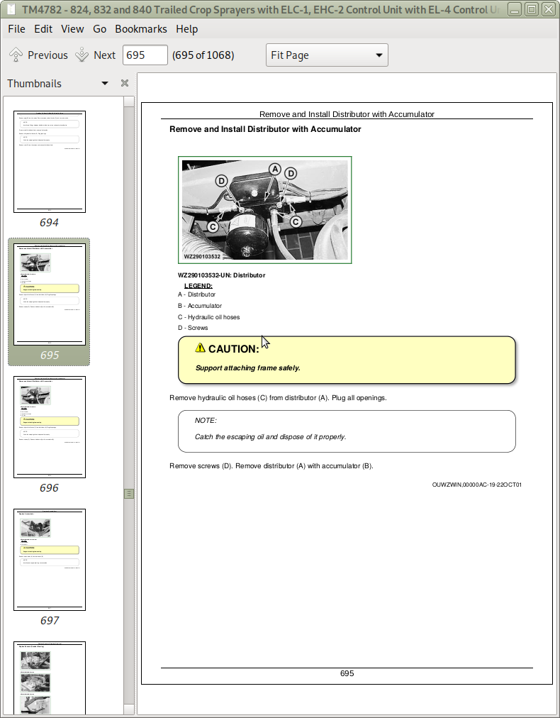
Remove and Install Distributor with Accumulator
Replace Accumulator
Group 25: Sensors
Replace Sensors (Drawbar Steering)
Group 30: Adjustments
Adjust the Sequence Valves
Folding and Unfolding
Group 35: Hydraulic Diagrams
Hydraulic Diagrams, Standard or Hy-Select
Hydraulic Diagram for Sprayers with Double Folding Boom
Hydraulic Diagram for Sprayers with Triple Folding Boom
Section 80: Miscellaneous
Group 05: Welding and Repair
Unauthorized Modifications
Frame Repair
Welding
Emergency Crack Repair
Emergency “T” Joint Repair
Skip Welding
Stress Relief (Normalizing)
Group 10: Function Diagrams
Function Diagram Sprayer with Single Pump
Function Diagram Sprayer with Single Pump and VRS
Function Diagram Sprayer with Single Pump and Automatic Tank Filling
Function Diagram Sprayer with Single Pump, VRS and Automatic Tank Filling
Function Diagram Sprayer with Double Pump
Function Diagram Sprayer with Double Pump and VRS
Function Diagram Sprayer with Double Pump and Automatic Tank Filling
Function Diagram Sprayer with Double Pump, VRS and Automatic Tank Filling
Group 15: Sprayboom
Remove and Install Complete Sprayboom (On One Side)
Remove and Install End Section
Remove and Install Center Section
Remove and Install, Replace Starting Section
Replace Hinge Arm
Replace Spindle
Replace Tension Spring (On End Section)
Remove and Install Folding/Unfolding Cylinder
Repair Folding/Unfolding Cylinder
Remove and Install Transport Support/Roll (Center Section)
Remove and Install Transport Support (Starting Section)
Remove and Install Locking Stay (20/15 und 21/15m)
Remove and Install Locking Stay (All Versions Except 20/15 und 21/15m)
Replace Pressure Roll for End Section (24/12; 28/14 and 30/15 m Versions Only)
Group 20: Sprayboom Adjustments
Specifications
Adjusting The Sprayboom Transport Position
Adjusting and Aligning the Sprayboom
Balancing Sprayboom
Group 25: Center Frame
Special Tools
Specifications
Other Material
Remove and Install Complete Attaching Frame
Replace Attaching Frame
Replace Gas Pressure Shock Absorber
Replace Bearing of Anti-Yaw Device
Replace Intermediate Bar
Replace Damper/Stop Wedge
Remove and Install Folding/Unfolding Cylinder
Repair Folding/Unfolding Cylinder
Remove and Install Locking Cylinder
Repair Locking Cylinder
Remove and Install Connecting Rod
Replace Deflector Roll of Hook Tension Cable
Replace Hook Tension Cable
Adjust Hook Tension Cable
Replace Transport Roll/Wear Plates
Replace Hook
Remove and Install Balancing Springs
Replace Guide Strips (on Attaching Frame)
Adjusting The Center Frame
Replace Guide Strips (on Guide Tube)
Group 30: Track Width Adjustment
Track Width Adjustment With Sliding Axle
Group 35: Axle
Special Tools
Specifications
Other Material
Remove and Install Axle
Remove and Install Spring Element or Support
Replace Speed Sensor
Replace Taper Roller Bearings (Wheel Hub)
Amount of Grease For Each Wheel Hub
Check Brake Drum
Replace Brake Drum or Magnet Wheel
Check Brake Linings, Replace Brakes Shoes
Brake Adjustment
Remove and Install Linkage Adjuster
Remove and Install Brake Camshaft (Adjustable Axle)
Remove and Install Brake Camshaft (Fixed Axle)
Group 40: Drawbar Adjustments
Installing the Lower Linkage Drawbar (Automatic Tracking System)
Universal Drawbar Pivot
Installing the Universal Drawbar (Automatic Tracking System)
Adjusting the Automatic Tracking System With Lower Linkage Drawbar
Adjusting The Automatic Tracking System With Universal Drawbar
Steering Cylinder Speed Adjustment
Group 45: Drawbar
Specifications
Other Material
Remove and Install Tow Eye or Connecting Frame
Remove and Install Drawbar
Group 50: Parallelogram
Remove and Install Parallelogram Arm (Top)
Remove and Install Parallelogram Arm (Bottom)
Section 100: Tank and Accessories
Group 05: Spraying Liquid Tank
Other Material
Replace Breather Valve/Tank Lid/Hinge Arm/Edge Cover
Replace Breather Valve
Replace Tank Lid Adapter
Replace Tank Level Indicator
Replace Float Cable/Float Guide/Float
Replace Injectors for Agitation
Remove and Install Tank
Group 10: Rinse Tank
Replace Breather Valve
Remove and Install Rinse Tank
Section 110: Pump
Group 05: Pump
Other Material
Remove and Install Pump
Disassemble and Assemble Pump
Seal Pump
Replace Accumulator Diaphragm
Section 120: Lines and Valves
Group 05: Sprayline
Remove and Install Line Filter
Replace Two-Way Ball Valve
Repair Two-Way Ball Valve
Replace Air Distributor Section
Replace 3/4” Solenoid Valve
Section 130: Activation Systems
Group 05: Sensors
Replace Flow Sensor (If Equipped)
Replace Liquid Pressure Sensor (If Equipped)
Replace Air Pressure Sensor
Group 10: Boom Tilt Cylinder
Specifications
Other Material
Remove and Install Boom Tilt Cylinder
Adjust Electrical Boom Tilt Cylinder with EL-4 Control
Adjust Boom Tilt Cylinder (ELC-1 and EHC-2 Control Unit)
Group 15: Ball Valves
Remove and Install Protective Cap on L.H. Side
Repair and Seal Four-Way Ball Valve (Pressure Selection Valve)
Replace Injector Shut-Off Valve
Repair and Seal Injector Shut-Off Valve
Replace Agitation Shut-Off Valve
Remove and Install Four-Way Ball Valve (Spraying Pump Suction Unit)
Remove and Install Four-Way Ball Valve (Agitation Pump Suction Unit)
Repair and Seal Four-Way Ball Valve (Suction Valve)
Remove and Install Three-Way VRS Suction Valve (If Equipped)
Remove and Install Drain Valve
Repair and Seal Drain Valve
Remove and Install Three-Way Electrical Ball Valve
Repair and Seal Three-Way Electrical Ball Valve
Group 20: Regulating Unit
Remove and Install Complete Regulating Unit
Disassemble and Assemble Regulating Unit
Remove and Install Primary Pressure Regulator
Repair Primary Pressure Regulator
Replace Diaphragm of Electrical Pressure Regulator
Replace Motor of Electrical Pressure Regulator
Replace Upper Microswitch of Electrical Pressure Regulator
Replace Lower Microswitch of Electrical Pressure Regulator
Replace Socket in Electrical Pressure Regulator
Remove and Install Pressure Filter
Remove and Install Suction Filter(s)
Remove and Install Three-Way Diverter Valve
Repair Three-Way Diverter Valve
Group 25: Air Pressure Regulating Unit
Replace Air Filter Restriction Indicator
Remove and Install Air Filter for Compressor
Remove and Install Sound Absorber
Remove and Install Complete Air Pressure Regulating Unit
Disassemble and Assemble Air Pressure Regulating Unit
Section 140: Spray Nozzles
Group 05: Spray Nozzles
Remove and Install Nozzle Holder with Nozzle
Replace Diaphragm
Seal Carrousel
Section 160: VRS
Group 05: Distributor Tube
Remove and Install VRS Filter
Remove and Install Non Return Valve
Replace Distributor Tube
![]()