
John Deere Trailed Crop Sprayers M724, M732, M740, M732i, M740i Diagnosis & Tests Service Manual (TM407219)
Complete service Diagnosis & Tests manual with electrical wiring diagrams for John Deere Trailed Crop Sprayers M724, M732, M740, M732i, M740i (European Edition), with all the shop information to maintain, diagnose, and service like professional mechanics.
John Deere Trailed Crop Sprayers M724, M732, M740, M732i, M740i workshop Operation & Test manual includes:
* Numbered table of contents easy to use so that you can find the information you need fast.
* Detailed sub-steps expand on repair procedure information
* Numbered instructions guide you through every repair procedure step by step.
* Troubleshooting and electrical service procedures are combined with detailed wiring diagrams for ease of use.
* Notes, cautions and warnings throughout each chapter pinpoint critical information.
* Bold figure number help you quickly match illustrations with instructions.
* Detailed illustrations, drawings and photos guide you through every procedure.
* Enlarged inset helps you identify and examine parts in detail.
TM407219 - John Deere Trailed Crop Sprayers M724, M732, M740, M732i, M740i Service Manual (Diagnosis & Tests).PDF
Total Pages: 1,459 pages
File Format: PDF (bookmarked, ToC, Searchable, Printable, high quality)
Language: English
MAIN SECTIONS
Foreword
General Information
Safety
Diagnostic Trouble Codes
Spray Rate Control Software Diagnostic Trouble Codes (SPC)
Observable Symptom and System Diagnostics
Electrical
Electronic Control Units
Steering and Brakes
Hydraulics
Solution System
Electrical
General Information
Operational and Preliminary Checks
Theory of Operation
Schematic
Diagnostic Tests and Adjustments
Electronic Control Units
General Information
Operational and Preliminary Checks
Interactive Tests and Calibrations
Programming Electronic Control Units
Theory of Operation
Schematic
Diagnostic Tests and Adjustments
Spray Rate Control (SPC) Software Addresses
Electrical Component Information
Electrical Assemblies
Sensors
Lights
Monitoring Devices
Relays
Motors
Switches
Interconnects and Ground Points
Electronically Actuated Mechanical Devices
Steering and Brakes
General Information
Theory of Operation
Schematic
Diagnostic Tests and Adjustments
Hydraulics
General Information
Theory of Operation
Schematic
Diagnostic Tests and Adjustments
Hydraulics Component Information
Accumulators
Cylinder, Actuator, or Piston
Check Valve
Filter
Valve Block, Assembly, or Gearcase
Motor
Orifice
Valve
Solenoid Valve
Solution System
General Information
Theory of Operation
Schematic
Diagnostic Tests and Adjustments
tm407219 - M724, M732, M740, M732i, and M740i Trailed Crop Sprayers Diagnostic Technical Manual -: (European Edition)
Table of Contents
Foreword
Section 210: General Information
Group 05: Safety
Recognize Safety Information
Understand Signal Words
Follow Safety Instructions
Handle Fluids Safely—Avoid Fires
Prepare for Emergencies
In Case of Fire
Handle Agricultural Chemicals Safely
Service and Operate Chemical Sprayers Safely
Avoid Contact with Agricultural Chemicals
Clean Vehicle of Hazardous Pesticides
Wear Protective Clothing
Park Machine Safely
Support Machine Properly
Wear Protective Clothing
Work in Clean Area
Service Machines Safely
Stay Clear of Rotating Drivelines
Use Steps and Handholds Correctly
Work In Ventilated Area
Illuminate Work Area Safely
Replace Safety Signs
Use Proper Lifting Equipment
Avoid High-Pressure Fluids
Service Accumulator Systems Safely
Remove Paint Before Welding or Heating
Avoid Heating Near Pressurized Fluid Lines
Service Tires Safely
Follow Tire Recommendations
Avoid Harmful Asbestos Dust
Practice Safe Maintenance
Protect Against High Pressure Spray
Use Proper Tools
Construct Dealer-Made Tools Safely
Decommissioning — Proper Recycling and Disposal of Fluids and Components
Servicing Electronic Control Units
Welding Near Electronic Control Units
Keep Electronic Control Unit Connectors Clean
Precautions for Welding
Live With Safety
Section 211: Diagnostic Trouble Codes
Group SPC: Spray Rate Control Software Diagnostic Trouble Codes (SPC)
SPC 168.03 - High Battery Voltage
SPC 168.04 - Low Battery Voltage
SPC 1883.00 - PTO Speed Above 540 rpm
SPC 2128.09 - Connection to VT Lost (Display)
SPC 2160.09 - Connection to EPM1 Lost (Base)
SPC 2199.09 - Connection to Control Unit Lost (Multi-Function Lever)
SPC 2205.09 - Connection to BoomTrac Lost
SPC 2394.05 - Work Light Open Load
SPC 2394.06 - Work Light Short to Ground or Over Current
SPC 520300.02 - Left BoomTrac Sensor Out of Range
SPC 520301.02 - Right BoomTrac Sensor Out of Range
SPC 520402.05 - Pendulum Lock ON Open Load
SPC 520402.06 - Pendulum Lock ON Short to Ground or Over Current
SPC 520403.05 - Pendulum Lock OFF Open Load
SPC 520403.06 - Pendulum Lock OFF Short to Ground or Over Current
SPC 520503.06 - Right Outer Tip Short to Ground or Over Current
SPC 520504.06 - Left Outer Tip Short to Ground or Over Current
SPC 520601.05 - Free Function or Beacon Light Open Load
SPC 520601.06 - Free Function or Beacon Light Short to Ground or Over Current
SPC 520704.00 - Pump 1 Oil Level High
SPC 520704.01 - Pump 1 Oil Level Low
SPC 521326.06 - Power Circuit — Sections R1 to R5 — Short to Ground or Over Current
SPC 521327.06 - Power Circuit — Sections L1 to L5 — Short to Ground or Over Current
SPC 521328.06 - Power Circuit — Section C — Short to Ground or Over Current
SPC 521331.06 - Pressure Regulator 1 Bridge A Short to Ground or Over Current
SPC 521332.06 - Pressure Regulator 1 Bridge B Short to Ground or Over Current
SPC 521337.05 - AutoDilute Pump Hydraulic Valve Open Load
SPC 521337.06 - AutoDilute Pump Hydraulic Valve Short to Ground or Over Current
SPC 521347.05 - On-Board Air Compressor Open Load
SPC 521347.06 - On-Board Air Compressor Short to Ground or Over Current
SPC 521353.06 - Master Valve Circulation (Rear) Short to Ground or Over Current
SPC 521382.06 - Agitation Short to Ground or Over Current
SPC 523219.06 - Power Circuit — Master Valve 1, Master Valve 2, and Agitation— Short to Ground or Over Current
SPC 523382.06 - Agitation Short to Ground or Over current
SPC 523405.06 - Main Fill Valve Short to Ground or Over Current
SPC 523409.05 - Drawbar Right Open Load
SPC 523409.06 - Drawbar Right Short to Ground or Over Current
SPC 523410.05 - Drawbar Left Open Load
SPC 523410.06 - Drawbar Left Short to Ground or Over Current
SPC 523411.05 - Height Adjustment DOWN Open Load
SPC 523411.06 - Height Adjustment DOWN Short to Ground or Over Current
SPC 523412.05 - Boom Tilt Left Open Load
SPC 523412.06 - Boom Tilt Left Short to Ground or Over Current
SPC 523413.05 - Boom Tilt Right Open Load
SPC 523413.06 - Boom Tilt Right Short to Ground or Over Current
SPC 523414.05 - Height Adjustment UP Open Load
SPC 523414.06 - Height Adjustment UP Short to Ground or Over Current
SPC 523417.05 - LS Solenoid Open Load
SPC 523417.06 - LS Solenoid Short to Ground or Over Current
SPC 523418.05 - Horn Open Load
SPC 523418.06 - Horn Short to Ground or Over Current
SPC 523422.06 - Section Valve Center Water Short to Ground or Over Current
SPC 523423.06 - Right Fence/Edge Spray Nozzle Short to Ground or Over Current
SPC 523430.06 - Section Valve Water R5 Short to Ground or Over Current
SPC 523432.06 - Section Valve Water R4 Short to Ground or Over Current
SPC 523434.06 - Section Valve Water R3 Short to Ground or Over Current
SPC 523435.06 - Section Valve Water R2 Short to Ground or Over Current
SPC 523439.06 - Section Valve Water R1 Short to Ground or Over Current
SPC 523443.06 - Left Fence/Edge Spray Nozzle Short to Ground or Over Current
SPC 523448.06 - Section Valve Water L5 Short to Ground or Over Current
SPC 523450.06 - Section Valve Water L4 Short to Ground or Over Current
SPC 523452.06 - Section Valve Water L3 Short to Ground or Over Current
SPC 523453.06 - Section Valve Water L2 Short to Ground or Over Current
SPC 523454.06 - Section Valve Water L1 Short to Ground or Over Current
SPC 523465.05 - Boom Fold Tip Left OUT Open Load
SPC 523465.06 - Boom Fold Tip Left OUT Short to Ground or Over Current
SPC 523466.05 - Boom Fold Tip Left IN Open Load
SPC 523466.06 - Boom Fold Tip Left IN Short to Ground or Over Current
SPC 523469.05 - Boom Fold Right OUT Open Load
SPC 523469.06 - Boom Fold Right OUT Short to Ground or Over Current
SPC 523470.05 - Boom Fold Right IN Open Load
SPC 523470.06 - Boom Fold Right IN Short to Ground or Over Current
SPC 523471.05 - Boom Fold Tip Right IN Open Load
SPC 523471.06 - Boom Fold Tip Right IN Short to Ground or Over Current
SPC 523472.05 - Boom Fold Tip Right OUT Open Load
SPC 523472.06 - Boom Fold Tip Right OUT Short to Ground or Over Current
SPC 523479.05 - Variable Geometry Left DOWN Open Load
SPC 523479.06 - Variable Geometry Left DOWN Short to Ground or Over Current
SPC 523480.05 - Variable Geometry Right DOWN Open Load
SPC 523480.06 - Variable Geometry Right DOWN Short to Ground or Over Current
SPC 523481.05 - Variable Geometry Left UP Open Load
SPC 523481.06 - Variable Geometry Left UP Short to Ground or Over Current
SPC 523482.05 - Variable Geometry Right UP Open Load
SPC 523482.06 - Variable Geometry Right UP Short to Ground or Over Current
SPC 523652.02 - Control Unit Identification Error
SPC 523862.02 - ECU Supply Voltage Out of Range
Section 212: Observable Symptom and System Diagnostics
Group 40: Electrical
Agitation
Boom Fold
Boom Raise and Lower
Boom Tilt
BoomTrac
Boom Variable Geometry
CAN Bus
Control Unit Power — EPM
Control Unit Power — SPC
Hydraulic System Type
John Deere TerrainControl Pro
Lights — Work
Multifunction Control Lever
Power Distribution
Solution Pressure
Solution Pump Oil Level
Solution System Auto-Dilute
Solution System — Filling With Sprayer Pump
Spray Rate Control
Spray Valve Control
Tank Water Level
Wheel Speed
Group 45: Electronic Control Units
Control Unit — BoomTrac (IPC) — Electrical — Observable Symptoms
Control Unit — EPM Base (PC0) — Electrical — Observable Symptoms
Control Unit — John Deere TerrainControl Pro (?80) — Electrical — Observable Symptoms
Control Unit — Spray Rate Control (SPC) — Electrical — Observable Symptoms
Group 60: Steering and Brakes
Hydraulic Emergency Brake — Observable Symptoms
Drawbar Steering — Observable Symptoms
Group 70: Hydraulics
Overall Hydraulics
Auto-Dilute Hydraulic System
Boom Fold Hydraulic System
Boom Pendulum Lock Hydraulic System
Boom Raise Hydraulic System
Boom Tilt Hydraulic System
Boom Variable Geometry Hydraulic System
Drawbar Steering Hydraulic System
Hydraulic System Type
Group 80: Solution System
Solution System Diagnostics
Section 240: Electrical
Group 05: General Information
How to Use the Electrical Diagnostic Section
Electrical Schematic Symbols
Intermittent Fault Diagnostics
Group 10: Operational and Preliminary Checks
Circuit Checks — Electrical System
Group 20: Theory of Operation
Air System — Electrical — Theory of Operation
Agitation — Electrical — Theory of Operation
AutoDilute — Electrical — Theory of Operation
Beacon Light — Electrical — Theory of Operation
Boom Unfold and Fold — Electrical — Theory of Operation
Boom Raise and Lower — Electrical — Theory of Operation
Boom Tilt — Electrical — Theory of Operation
BoomTrac — Electrical — Theory of Operation
Boom Variable Geometry — Electrical — Theory of Operation
CAN Bus — Electrical — Theory of Operation
Drawbar Steering — Electrical — Theory of Operation
Hydraulic System Type — Electrical — Theory of Operation
Implement Display 1100 Power — Electrical — Theory of Operation
John Deere TerrainControl Pro — Electrical — Theory of Operation
Multi-Function Lever — Electrical — Theory of Operation
Power Distribution — Electrical — Theory of Operation
Public Road Travel Lights — Electrical — Theory of Operation
Solution Pressure — Electrical — Theory of Operation
Solution Pump Oil Level — Electrical — Theory of Operation
Spray Rate Control — Electrical — Theory of Operation
Spray Valve Control — Electrical — Theory of Operation
Solution System — Filling With Sprayer Pump — Electrical — Theory of Operation
Solution System — Pump Speed — Electrical — Theory of Operation
Solution Tank Level — Electrical — Theory of Operation
Wheel Speed — Electrical — Theory of Operation
Work Lights — Electrical — Theory of Operation
Group 30: Schematic
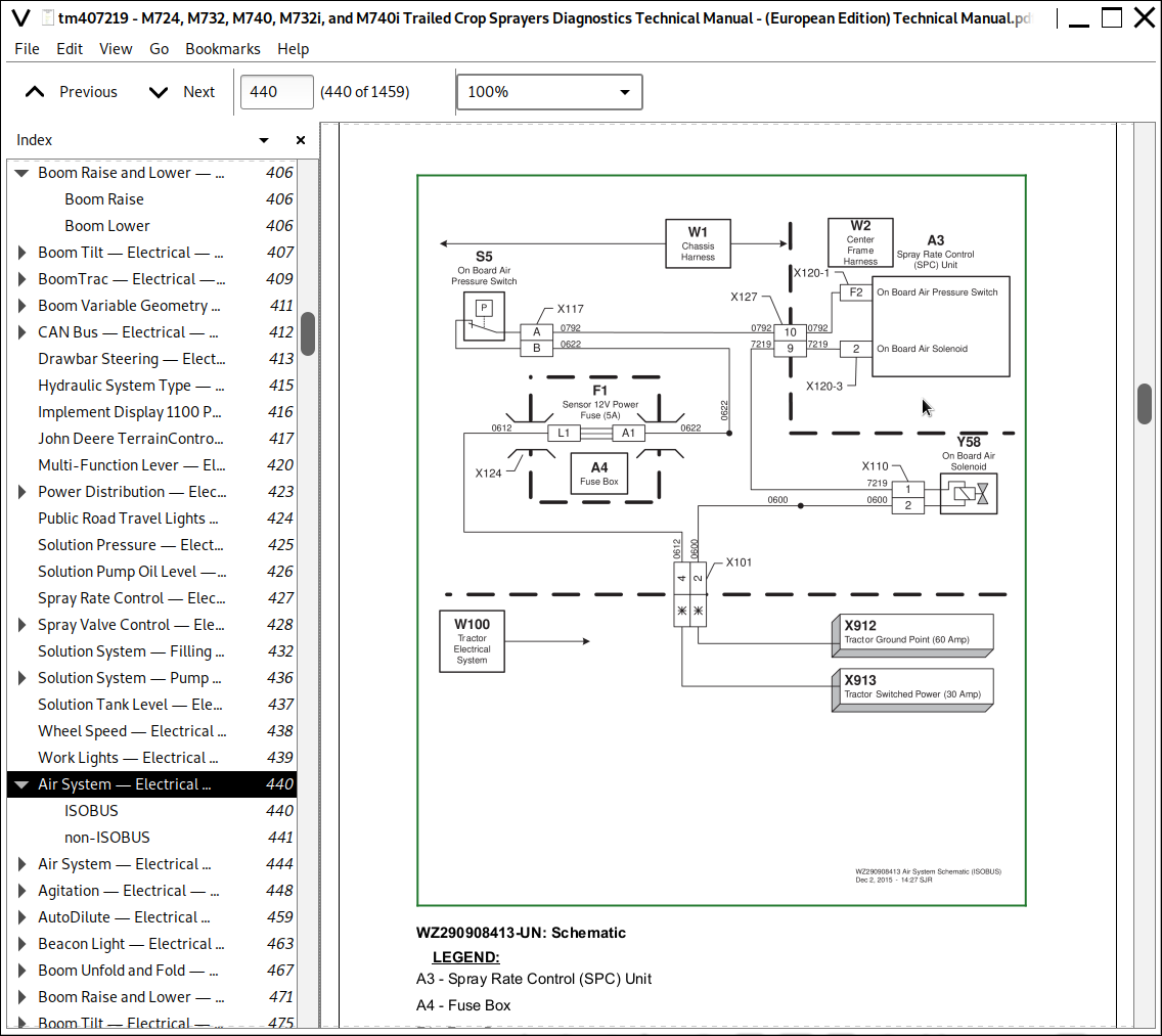
Air System — Electrical — Schematic
Agitation — Electrical — Schematic
AutoDilute — Electrical — Schematic
Beacon Light — Electrical — Schematic
Boom Unfold and Fold — Electrical — Schematic
Boom Raise and Lower — Electrical — Schematic
Boom Tilt — Electrical — Schematic
BoomTrac — Electrical — Schematic (S.N. –160269)
BoomTrac — Electrical — Schematic (S.N. 160270–)
Boom Variable Geometry — Electrical — Schematic
CAN Bus — Electrical — Schematic
Diaphragm Pump Speed Sensor — Electrical — Schematic
Drawbar Steering — Electrical — Schematic
Hydraulic System Type — Electrical — Schematic
Implement Display 1100 Power — Electrical — Schematic
John Deere TerrainControl Pro — Electrical — Schematic
Multi-Function Lever — Electrical — Schematic
Power Distribution — Electrical — Schematic
Power Supply Adapter Harness — Electrical — Schematic
Public Road Travel Lights Schematic
Public Road Travel Lights Schematic — Denmark
Public Road Travel Lights Schematic — France
Solution Pressure — Electrical — Schematic
Solution Pump Oil Level — Electrical — Schematic
Spray Rate Control — Electrical — Schematic
Spray Valve Control — Standard and Ringline — (S.N. —0150000) —Electrical — Schematic
Spray Valve Control — Standard and Ringline — (S.N. 0150001— ) —Electrical — Schematic
Spray Valve Control — Pressure Recirculation — Electrical — Schematic
Solution System — Filling With Sprayer Pump — Electrical — Schematic
Solution Tank Level — Electrical — Schematic
Wheel Speed — Electrical — Schematic
Work Lights — Electrical — Schematic
Group 50: Diagnostic Tests and Adjustments
CAN Bus — Electrical — Diagnostics
Multi-Function Lever — Electrical — Diagnostics
BoomTrac — Electrical — Diagnostics
Adjust On Board Air Pressure Switch
Section 245: Electronic Control Units
Group 05: General Information
Servicing Electronic Control Units
Welding Near Electronic Control Units
Keep Electronic Control Unit Connectors Clean
Group 10A: Operational and Preliminary Checks
Factory Settings
Factory Settings (A) - General
Factory Settings - Sensor 1
Factory Settings - Sensor 2
Boom Settings (B) - Boom 1
Boom Settings - Boom 2
Boom Settings - Boom 3
Tank Settings (C) - Tank 1
Tank Settings - Tank 2
Dead Volumes for AutoDilute
Regulation Settings - Regulation 1
Regulation Settings - Regulation 2
Regulation Settings - Regulation 3
Alarm Settings - Alarm (Not Used)
Group 10B: Interactive Tests and Calibrations
Calibration Procedure — Boom Height (BoomTrac)
Calibration Procedure — Boom Tilt
Calibration Procedure — Flow Meter
Calibration Procedure — Solution Pressure Sensor
Calibration Procedure — Solution Tank Level Sensor
Calibration Procedure — Wheel
Group 10C: Programming Electronic Control Units
General Programming Information
Programming Control Units
Procedure in the Event of a Programming Problem
Loading Languages to Implement Display 1100
Group 20: Theory of Operation
Control Unit — Electronic Power Module (EPM) — Electrical — Theory of Operation
Control Unit — John Deere TerrainControl Pro — Electrical — Theory of Operation
Control Unit — Spray Rate Control (SPC) — Electrical — Theory of Operation
Control Unit — BoomTrac (IPC) — Electrical — Theory of Operation
Group 30: Schematic
Control Unit — BoomTrac (IPC) — Schematic (S.N. –160269)
Control Unit — BoomTrac (IPC) — Schematic (S.N. 160270–)
Control Unit — John Deere TerrainControl Pro — Schematic
Control Unit — Spray Rate Control (SPC) — Schematic
Control Unit — Electronic Power Module (EPM) — Electrical — Schematic
Group 50: Diagnostic Tests and Adjustments
Control Unit — BoomTrac (IPC) — Electrical — Diagnostics
Control Unit — EPM Base (PC0) — Electrical — Diagnostics
Control Unit — John Deere TerrainControl Pro — Electrical — Diagnostics
Control Unit — Spray Rate Control (SPC) — Electrical — Diagnostics
Group SPC: Spray Rate Control (SPC) Software Addresses
Diagnostic Addresses — SPC — Spray Rate Control Unit
Section 249: Electrical Component Information
Group 40A: Electrical Assemblies
X101 — ISOBUS Connector
X120-1 — Spray Rate Control (SPC) Control Unit (J1 - Brown)
X120-2 — Spray Rate Control (SPC) Control Unit (J2 - Grey)
X120-3 — Spray Rate Control (SPC) Control Unit (J3 - Black)
X121-1 — Electronic Power Module (EPM) (A - Green)
X121-2 — Electronic Power Module (EPM) (B - Black)
X121-3 — Electronic Power Module (EPM) (C - Blue)
X123 — Spray Rate Control (SPC) Control Unit Power
X124 — Fuse Box
X160 — CAN Bus Passive Terminator
X251 — CAN Bus Passive Terminator (with BoomTrac) (S.N. –160269)
X252 — Power BoomTrac
X256 — BoomTrac Control Unit (S.N. –160269)
X258 — BoomTrac Control Unit (S.N. 160270–)
X259 — BoomTrac Control Unit (S.N. 160270–)
X318 — Display
X355 — Passive Terminator
X367 — Boom Control Controller Connector
X378 — Boom Control Controller to Junction Block
X379 — Junction Block to Boom Control Controller
X461 — Left-Hand Terminator to Junction Block
X463 — Right-Hand Terminator to Junction Block
X464 — Junction Block to Left-Hand Terminator
X466 — Junction Block to Right-Hand Terminator
X910 — Display
Group 40B: Sensors
X103 — Diaphragm Pump Speed Sensor
X104 — Solution Pump 1 Oil Level Sensor
X114 — Tank Level Pressure Sensor
X115 — Wheel Speed Sensor
X174 — Solution Pressure Sensor
X175 — Flow Meter
X187 — Boom Height Sensor
X188 — Boom Tilt Sensor
X254 — Left-Hand BoomTrac Sensor
X255 — Right-Hand BoomTrac Sensor
X304 — Left-Hand Rear Drawbar Sensor
X305 — Right-Hand Rear Drawbar Sensor
X306 — Left-Hand Front Drawbar Sensor
X307 — Right-Hand Front Drawbar Sensor
X458 — Left-Hand Sensor to Terminator
X460 — Right-Hand Sensor to Terminator
Group 40E: Lights
X185 — Beacon Light
X291 — Left-Hand Work Light
X292 — Right-Hand Work Light
X526 — Left-Hand Tail, Turn, and Stop Light
X527 — Right-Hand Tail, Turn, and Stop Light
X530 — Left-Hand Front Marker Light
X531 — Right-Hand Front Marker Light
X536 — Left-Hand Side Marker Light 1
X537 — Left-Hand Side Marker Light 2
X538 — Left-Hand Side Marker Light 3
X539 — Left-Hand Side Marker Light 4
X540 — Right-Hand Side Marker Light 1
X541 — Right-Hand Side Marker Light 2
X542 — Right-Hand Side Marker Light 3
X543 — Right-Hand Side Marker Light 4
X544 — Left-Hand Rear Marker Light
X545 — Right-Hand Rear Marker Light
Group 40H: Monitoring Devices
X107 — Horn
Group 40K: Relays
X312 — Switched Power Delay Relay
Group 40M: Motors
X118 — Spray Rate Regulator Motor
X134 — Agitation Regulator Motor
X148 — Master Valve Recirculation Motor 1
X150 — Main Fill Valve Motor
X161 — Master Valve Recirculation Motor 2
X420 — R1 Water Control Motor
X421 — R2 Water Control Motor
X422 — R3 Water Control Motor
X423 — R4 Water Control Motor
X424 — R5 Water Control Motor
X426 — Center Water Control Motor
X427 — L1 Water Control Motor
X428 — L2 Water Control Motor
X429 — L3 Water Control Motor
X430 — L4 Water Control Motor
X431 — L5 Water Control Motor
X434 — Left-Hand Off-Center Valve Motor
X435 — Right-Hand Off-Center Valve Motor
Group 40S: Switches
X117 — On Board Air Pressure Switch
X138 — Filling Switch
X189 — Boom In Switch
X302 — Boom Lock Pressure Switch
X308 — Boom On Transport Switch
Group 40X: Interconnects and Ground Points
X001 — Multi-Function Lever
X002 — Connector Switchbox
X126 — Chassis Harness to Center Frame Harness 1
X127 — Chassis Harness to Center Frame Harness 2
X152 — Center Frame Harness to Left-Hand Boom Connector 1
X155 — Center Frame Harness to Right-Hand Boom Connector 1
X159 — Center Frame Harness to Boom Control Harness
X162 — Tilt Ground (With BoomTrac)
X163 — Tilt Ground (Without BoomTrac)
X186 — Boom Center Frame Harness to Work Light Harness
X192 — Center Frame Harness to Left-Hand Boom Connector 2
X193 — Center Frame Harness to Right-Hand Boom Connector 2
X194 — Center Frame Harness to Left-Hand Boom Connector 2
X195 — Center Frame Harness to Left-Hand Boom Connector 3
X196 — Center Frame Harness to Right Hand Boom Connector 2
X250 — BoomTrac Harness to Center Frame Harness (CAN Bus)
X257 — Tilt Ground 2 (With BoomTrac)
X309 — Chassis Harness to Drawbar Extension Harness
X310F — Center Frame Harness to Boom Height Sensor Extension Harness
X310M — Chassis Harness to Tractor Harness (non-ISOBUS Tractors)
X311 — Chassis Harness to Cab Harness (non-ISOBUS Tractors)
X313 — Center Frame Harness to Boom Control Harness
X315 — Cab Harness to StarFire Extension Harness
X316 — Cab Harness to Multi-Function Lever Harness
X317 — CAN Active Terminator
X319 — Service ADVISOR Connector
X345 — Chassis Harness to Center Frame Harness 3
X352 — Boom Control Harness to Center Frame Harness
X353 — Boom Control Harness to Center Frame Harness
X354 — Boom Control Harness to Center Frame Harness
X453 — Left-Hand BoomTrac Sensor Connector
X454 — Right-Hand BoomTrac Sensor Connector
X525 — Tractor Implement 7-Pin Connector
X528 — Left-Hand Front Marker Harness
X529 — Right-Hand Front Marker Harness
X532 — Left-Hand Tail Light Extension Harness
X533 — Right-Hand Tail Light Extension Harness
X534 — Left-Hand Side Marker Harness
X535 — Right-Hand Side Marker Harness
X546 — Left-Hand Rear Marker Harness
X547 — Right-Hand Rear Marker Harness
X911 — Tractor Ground Point (30 Amp)
X912 — Tractor Ground Point (60 Amp)
X913 — Tractor Switched Power (30 Amp)
X914 — Tractor Unswitched Power (60 Amp)
X915 — Tractor Unswitched Power
X916 — Tractor Switched Power
X917 — Tractor Ground
X900 — Tractor - Implement Connector
X901 — Tractor Cab Harness
X903 — Cab Harness to Display Harness
X920 — Tractor 7-Pin Connector
X999 — Valve Power Harness to Center Frame Harness
Group 40Y: Electronically Actuated Mechanical Devices
X106 — Open Center or Load Sense Hydraulics Solenoid
X110 — On Board Air Solenoid
X111 — Auto Dilute Pump Solenoid
X112 — Steer Left-Hand Solenoid
X113 — Steer Right-Hand Solenoid
X165 — Variable Geometry Left-Hand Up Solenoid
X166 — Variable Geometry Right-Hand Up Solenoid
X167 — Inner Boom Fold In 2 Solenoid
X168 — Fold Tip Left-Hand In Solenoid
X169 — Fold Tip Right-Hand In Solenoid
X170 — Inner Boom Fold In 1 Solenoid
X171 — Pendulum Lock On Solenoid
X172 — Boom Tilt Right-Hand Solenoid
X173 — Boom Up Solenoid
X176 — Variable Geometry Left-Hand Down Solenoid
X177 — Variable Geometry Right-Hand Down Solenoid
X178 — Inner Boom Fold Out 2 Solenoid
X179 — Fold Tip Left-Hand Out Solenoid
X180 — Fold Tip Right-Hand Out Solenoid
X181 — Inner Boom Fold Out 1 Solenoid
X182 — Pendulum Lock Off Solenoid
X183 — Boom Tilt Left-Hand Solenoid
X184 — Boom Down Solenoid
X303 — Boom Height Lock Solenoid
X400 — R1 Spray Valve Solenoid
X401 — R2 Spray Valve Solenoid
X402 — R3 Spray Valve Solenoid
X403 — R4 Spray Valve Solenoid
X404 — R5 Spray Valve Solenoid
X406 — Center Spray Valve Solenoid
X407 — L1 Spray Valve Solenoid
X408 — L2 Spray Valve Solenoid
X409 — L3 Spray Valve Solenoid
X410 — L4 Spray Valve Solenoid
X411 — L5 Spray Valve Solenoid
X413 — Right Inner Edge Spray Valve Solenoid
X414 — Right Outer Edge Spray Valve Solenoid
X415 — Left Inner Edge Spray Valve Solenoid
X416 — Left Outer Edge Spray Valve Solenoid
Section 260: Steering and Brakes
Group 05: General Information
Brake System Component Identification
Standard Hydraulic Symbols
Hydraulic Designators
Hydraulic System Testing Precautions
Visually Inspect Hydraulic System
Hydraulic Troubleshooting Tips
Aeration and Cavitation
Hydraulic Components
Oil Storage and Filling
Oil Filtration
Group 20: Theory of Operation
Hydraulic Braking System Theory of Operation
Pneumatic Braking System Theory of Operation
Group 30: Schematic
Hydraulic brakes 700 Schematic
Hydraulic Braking System Schematic
Pneumatic Braking System Schematic
Group 50: Diagnostic Tests and Adjustments
Hydraulic Brake Diagnostics
Pneumatic Brakes Diagnostics
Section 270: Hydraulics
Group 05: General Information
Standard Hydraulic Symbols
Hydraulic Designators
Hydraulic System Testing Precautions
Visually Inspect Hydraulic System
Hydraulic Troubleshooting Tips
Aeration and Cavitation
Hydraulic Components
Oil Storage and Filling
Oil Filtration
Group 20: Theory of Operation
AutoDilute — Hydraulic — Theory of Operation
Boom Fold — Hydraulic — Theory of Operation
Boom Pendulum Lock — Hydraulic — Theory of Operation
Boom Raise — Hydraulic — Theory of Operation
Boom Tilt — Hydraulic — Theory of Operation
Boom Variable Geometry — Hydraulic — Theory of Operation
Compressor — Hydraulic — Theory of Operation
Drawbar Steering — Hydraulic — Theory of Operation
Hydraulic Pump Drive — Hydraulic — Theory of Operation
System Type — Hydraulic — Theory of Operation
Overall System — Hydraulic — Theory of Operation
Group 30: Schematic
AutoDilute — Hydraulic — Schematic
Boom Fold — Hydraulic — Schematic
Boom Pendulum Lock — Hydraulic — Schematic
Boom Raise — Hydraulic — Schematic
Boom Tilt — Hydraulic — Schematic
Boom Variable Geometry — Hydraulic — Schematic
Drawbar Steering — Hydraulic — Schematic
System Type — Hydraulic — Schematic
Electrohydraulic System — Hydraulic — Schematic
Hydraulic Pump Drive — Hydraulic — Schematic
Hydraulic Selector System — Hydraulic — Schematic
Tractor SCV System — Hydraulic — Schematic
Hydraulic Valve Block Identification
Group 50: Diagnostic Tests and Adjustments
AutoDilute — Hydraulic — Diagnostics
Boom Pendulum Lock — Hydraulic — Diagnostics
Boom Raise — Hydraulic — Diagnostics
Boom Tilt — Hydraulic — Diagnostics
Boom Unfold and Fold — Hydraulic — Diagnostics
System Type — Hydraulic — Diagnostics
Variable Geometry — Hydraulic — Diagnostics
Section 279: Hydraulics Component Information
Group 40A: Accumulators
A01 — Boom Raise Accumulator
Group 40C: Cylinder, Actuator, or Piston
C01 — Left Lift Cylinder
C02 — Right Lift Cylinder
C03 — Drawbar Steering Cylinder (Single)
C04 — Left Drawbar Steering Cylinder
C05 — Right Drawbar Steering Cylinder
C06 — Boom Tilt Cylinder
C07 — Pendulum Lock Cylinder
C08 — Left Inner Boom Cylinder
C09 — Right Inner Boom Cylinder
C10 — Left Middle Boom Cylinder (3-Part Boom)
C11 — Right Middle Boom Cylinder (3-Part Boom)
C12 — Left Boom Tip Cylinder
C13 — Right Boom Tip Cylinder
C14 — Left Variable Geometry Boom Cylinder
C15 — Right Variable Geometry Boom Cylinder
Group 40D: Check Valve
D01, D03, D05, D07 — ”B” Port Check Valves
D02, D04, D06, D08, D10, D14, D16, D18, D20, D22 — ”A” Port Check Valves
D07, D09, D13, D15, D17, D19, D21 — ”B' Port Check Valves
D11 — On Board Air Hydraulic Motor Check Valve
D26 — Hydraulic System Pressure Coupler
D27 — Hydraulic System Return Coupler
D28 — Hydraulic System Load Sense Coupler
D29 — Hydraulic Pump Drive Check Valve
D30 — Hydraulic Pump Drive Return Check Valve
Group 40F: Filter
F01 — Filter
Group 40G: Valve Block, Assembly, or Gearcase
G01 — Flow Divider Valve Block
G03 — Drawbar Steering Variable Restrictor (Optional)
G04 — Drawbar Steering Variable Restrictor (Optional)
G05 — Left Wing Variable Geometry Flow Restrictor
G06 — Left Wing Variable Geometry Flow Restrictor
G07 — Right Wing Variable Geometry Flow Restrictor
G08 — Right Wing Variable Geometry Flow Restrictor
G10 — Boom Control Valve Assembly
G11 — Hydraulic Pump Drive Valve Assembly
Group 40M: Motor
M01 — AutoDilute Motor
M02 — Hydraulic Pump Drive Motor
M03 — On Board Air Hydraulic Motor
Group 40O: Orifice
O1 — Hydraulic System Orifice
O2 — Lift Orifice
O3, O4 — Drawbar Steering Orifices (Single Cylinder)
O5, O6 — Drawbar Steering Orifices (Dual Cylinder)
O7 — Boom Tilt Orifice
O8 — Boom Tilt Orifice
O9 — Pendulum Lock Orifice
O10 — Pendulum Lock Orifice
O11 — Inner Boom Fold 1 Orifice
O12 — Inner Boom Fold 1 Orifice
O13 — Inner Boom Fold 1 Orifice
O14 — Inner Boom Fold 1 Orifice
O15 — Inner Boom Fold 2 Orifice (3-Part Boom)
O16 — Inner Boom Fold 2 Orifice (3-Part Boom)
O17 — Inner Boom Fold 2 Orifice (3-Part Boom)
O18 — Inner Boom Fold 2 Orifice (3-Part Boom)
O19 — Left Tip Fold Orifice
O20 — Left Tip Fold Orifice
O21 — Right Tip Fold Orifice
O22 — Right Tip Fold Orifice
O23 — Load Sense Orifice
Group 40P: Pump
P01 — On Board Air Compressor Pump
Group 40V: Valve
V01 — Regulating Valve
V02 — Load Sense Bleed Valve
V03 — AutoDilute Flow Control Valve
V16 — Flow Regulator Valve
Group 40Y: Solenoid Valve
Y01 — Hydraulic Type Solenoid Valve
Y02 — On Board Air Flow Control Solenoid Valve
Y06, Y08, Y10, Y11, Y14, Y16, Y18, Y20, Y22, Y24 — Solenoid Valves
Y26 — AutoDilute Pump Valve
Y27 — Boom Height Lock Solenoid Valve
Y58 — On Board Air Solenoid
Section 280: Solution System
Group 05: General Information
How To Use This Section — Solution System
Filling Specifications
Group 20: Theory of Operation
AutoDilute Theory of Operation
Solution System (Standard) Theory of Operation
Solution System (with Ring Line) Theory of Operation
Solution System (with Pressure Recirculation) Theory of Operation
Group 30: Schematic
Function Diagram — Sprayer
Function Diagram — Sprayer with AutoDilute and AutoFill
Function Diagram — Sprayer with Ring Line Circulation System
Function Diagram — Sprayer with Ring Line Circulation System, AutoDilute and AutoFill
Function Diagram — Sprayer with Pressure Circulation System
Function Diagram — Sprayer with Pressure Circulation System, AutoDilute and AutoFill
Pressure Circulation Option
Group 50: Diagnostic Tests and Adjustments
Solution Load — Diaphragm Pump — Diagnostics
Solution System — Inductor — Diagnostics
Solution System — Spraying — Diagnostics
Solution System — Section Valve — Diagnostics
Solution System — Agitation — Diagnostics
Solution System — Rinse — Diagnostics
John Deere Trailed Crop Sprayers M724, M732, M740, M732i, M740i Diagnosis & Tests Service Manual (TM407219)
![]()