
John Deere Trailed Crop Sprayers M724, M732, M740, M732i, M740i Repair Service Manual (TM407319)

Complete service repair manual for John Deere Trailed Crop Sprayers M724, M732, M740, M732i, M740i, with technical information to maintain, repair, and service like professional mechanics.
John Deere Trailed Crop Sprayers M724, M732, M740, M732i, M740i workshop service & repair manual includes:
* Numbered table of contents easy to use so that you can find the information you need fast.
* Detailed sub-steps expand on repair procedure information
* Numbered instructions guide you through every repair procedure step by step.
* Notes, cautions and warnings throughout each chapter pinpoint critical information.
* Bold figure number help you quickly match illustrations with instructions.
* Detailed illustrations, drawings and photos guide you through every procedure.
* Enlarged inset helps you identify and examine parts in detail.
TM407319 - John Deere Trailed Crop Sprayers M724, M732, M740, M732i, M740i Service Manual (Repair).PDF
Total Pages: 819 pages
File Format: PDF (bookmarked, ToC, Searchable, Printable, high quality)
Language: English
MAIN SECTIONS
Foreword
Safety
Safety Information
General Information
Description of the Machine
Torques for Hardware
Specifications
Electrical System
Connector Repair
Sensors
Brake System
Hydraulic Brake System
Pneumatic Brake System
Hydraulic System
Hydraulic Functions
Hydraulic Cylinders
Control Valves
Accumulator
Frame and Spray Boom
Welding and Repair
Spray Boom
Center Frame
Axle
Drawbar
Parallelogram
Adjustments
Tanks and Accessories
Solution Tank
Rinse Tank
Hand Wash Tank
Polyethylene Tank Repair
Pump
Pump
Lines and Valves
Spray Line
Activation Systems
Flow Meter
Ball Valves
Regulating Unit
Spray Nozzles
Spray Nozzles
tm407319 - M724, M732, M740, M724i, M732i, and M740i Trailed Crop Sprayer Repair Technical Manual
Table of Contents
Foreword
Section 05: Safety
Group 05: Safety Information
Admissible Use
Recognize Safety Information
Understand Signal Words
Keep Riders Off Machine
Prepare for Emergencies
Use Safety Lights and Devices
Work in Clean Area
Chemical Safety
Handle Agricultural Chemicals Safely
Service and Operate Chemical Sprayers Safely
Danger Symbols
Mechanical Safety
Non-Permissible Use
Operators
Working Area
Wear Protective Clothing
Wear Protective Clothing
Illuminate Work Area Safely
Respiratory Protection
Skin Protection
Maintenance of Means of Personal Protection
Tractor Cab
Use Proper Lifting Equipment
Safety During Maintenance Work
Avoid High-Pressure Fluids
Service Accumulator Systems Safely
Service Tires Safely
Avoid Heating Near Pressurized Fluid Lines
Use Proper Tools
Construct Dealer-Made Tools Safely
Service Machines Safely
Remove Paint Before Welding or Heating
Servicing Electronic Control Units
Welding Near Electronic Control Units
Keep Electronic Control Unit Connectors Clean
General Machine Operation Safety
Transport in the Field and on the Road
Operate Safely
Live With Safety
Section 10: General Information
Group 05: Description of the Machine
Identification Views
Machine Composition
Group 10: General Information
Face Seal Fittings Assembly and Installation—All Pressure Applications
Metric Face Seal and O-Ring Stud End Fitting Torque Chart—Standard Pressures
Metric Face Seal and O-Ring Stud End Fitting Torque Chart—High Pressure Applications
SAE Face Seal and O-Ring Stud End Fitting Torque Chart—Standard Pressures
SAE Face Seal and O-Ring Stud End Fitting Torque Chart—High Pressure Applications
External Hexagon Port Plug Torque Chart
Metric Standpipe Torque Chart
British Connections
Identifying Zinc-Flake Coated Fasteners
Unified Inch Bolt and Screw Torque Values
Metric Bolt and Screw Torque Values
Metric Stainless Steel Bolt and Screw Torque Values
Programming Control Units
Programming Boom Control Module
Hydraulic Retuning
Automatic Setup
Preparing and Painting Sprayer Components
Group 15: Specifications
Capacities
Dimensions and Weights
Sound Level
Electrical Connection Requirements
Products to be Processed
Materials Used
Physical Operating Conditions
Lubricant Storage
Section 40: Electrical System
Group 05: Connector Repair
Essential or Recommended Tools
Electrical Connector Handling
Disconnecting Electrical Circuit
Connector Information
Installation of Repair Wire Assembly (RWA)
Repair Procedure R-A
Repair Procedure R-B
Repair Procedure R-C
Repair Procedure R-E
Repair Procedure R-F
Repair Procedure R-I
Repair Procedure R-AA
Repair Procedure R-AE
Repair Procedure R-AM
Repair Procedure R-AN
Repair Procedure R-AO
Repair Procedure R-AP
Repair Procedure R-AQ
Group 10: Electrical Components
Specifications
Remove and Install Automatic Tracking System Sensor (Steering Drawbar)
Remove and Install Center Position Sensors (Steering Drawbar)
Remove and Install Flow Sensor
Remove and Install Digital Level Indicator Sensor
Remove and Install Digital Level Indicator Alarm
Remove and Install Solution Pressure Sensor
Remove and Install Wheel Speed Sensor
Remove and Install Spray Boom Transport Lock Switch
Remove and Install Spray Boom Position Switch
Remove and Install Spray Boom Roll Sensor
Remove and Install Boom Control Unit
Remove and Install Boom Control Junction Block
Remove and Install Boom Control Boom Sensor
Section 60: Brake System
Group 05: Hydraulic Brake System
Hydraulic Brake System (Not for Germany)
Remove and Install Parking Brake Operating Assembly
Remove and Install Tension Cable Disk
Remove and Install Tension Cable
Adjust Parking Brake
Group 10: Pneumatic Brake System
Public Roads
Replace Coupling
Clean/Replace Line Filter Strainer
Replace Release Valve
Replace Brake Power Regulator
Replace Brake Valve
Replace Quick Release Valve or Switch Valve
Replace Shut-Off Valve
Replace Compressed Air Storage Tank
Replace Brake Cylinder
Section 70: Hydraulic System
Group 05: Hydraulic Functions
General Information
Group 10: Hydraulic Cylinders
Essential or Recommended Tools
Other Material
Specifications
Remove and Install Hydraulic Brake Cylinder
Disassemble and Assemble Hydraulic Brake Cylinder
Remove and Install Secondary Fold Cylinder
Disassemble and Assemble Secondary Fold Cylinder
Remove and Install Height Adjustment Cylinders
Remove and Install Pendulum Lock Cylinder
Disassemble and Assemble Pendulum Lock Cylinder
Remove and Install Boom Fold Cylinder
Remove and Install Spray Boom Roll Cylinder
Remove and Install Drawbar Steering Cylinder
Disassemble and Assemble Boom Fold, Boom Roll, and Drawbar Steering Cylinders
Remove and Install Variable Geometry Cylinder
Disassemble and Assemble Variable Geometry Cylinder
Disassemble and Assemble Hydraulic Fluid Pressure Restrictor Assembly
Group 15: Control Valves
Specifications
General Repair Information
Disassemble and Assemble Load Sensing Flow Control Valve
Disassemble and Assemble Hydraulic Valve Stack (Double Folding Boom)
Disassemble and Assemble Hydraulic Valve Stack (Triple Folding Boom)
Disassemble and Assemble Hydraulic Pump Drive Valve
Group 20: Accumulator
Other Material
Specifications
Remove and Install Hydraulic Distributor with Accumulator
Disassemble and Assemble Hydraulic Distributor with Accumulator
Section 80: Frame and Spray Boom
Group 05: Welding and Repair
Unauthorized Modifications
Frame Repair
Welding
Emergency Crack Repair
Emergency ”T” Joint Repair
Skip Welding
Stress Relief (Normalizing)
Group 10: Spray Boom
Prepare Sprayer for Service of Spray Boom
Remove and Install Breakaway Section
Remove and Install Breakaway Section Tension Spring
Remove and Install Outer Spray Boom Section
Remove and Install Inner Spray Boom Section or Complete Spray Boom (On One Side)
Remove and Install Center Spray Boom Frame
Remove and Install Spray Boom Hinge
Remove and Install Spindle
Remove and Install Pressure Roll for Breakaway Section
Remove and Install Spray Boom Transport Lock
Remove and Install Spray Boom Transport Support and Roll
Remove and Install Spray Boom Transport Bracket
Group 15: Center Frame
Remove and Install Center Attaching Frame
Remove and Install Protection Plates
Remove and Install Shock Absorber (Center Attaching Frame)
Remove and Install Shock Absorber (Anti-Yaw)
Remove and Install Anti-Yaw Shock Absorber Arm
Remove and Install Anti-Yaw Dampener
Remove and Install Center Frame Roll (Front)
Remove and Install Center Frame Roll (Rear)
Remove and Install Spray Boom Suspension Springs
Remove and Install Pendulum Lock
Group 20: Axle
Other Material
Specifications
Remove and Install Axle Assembly (Adjustable)
Remove and Install Adjustable Axle
Remove and Install Extension Spring
Remove and Install Brake Shoes and Camshaft (Adjustable Axle)
Remove and Install Camshaft Support (Adjustable Axle)
Remove and Install Roller Bearings (Wheel Hub)
Remove and Install Brake Drum or Back-Up Ring
Amount of Grease for Each Wheel Hub
Inspect Brake Drum, Brake Shoes, and Brake Linings
Group 25: Drawbar
Other Material
Specifications
Remove and Install Steering Drawbar
Remove and Install Tow Eye
Remove and Install Connecting Bracket (Steering Drawbar)
Group 30: Parallelogram
Other Material
Remove and Install Parallelogram Arm (Top)
Remove and Install Parallelogram Arm (Bottom)
Remove and Install Parallelogram Vertical Lift Arm
Remove and Install Parallelogram Lift Arm
Remove and Install Isolators
Group 35: Adjustments
Adjusting the Automatic Tracking System with Steering Drawbar
Adjust Steering Cylinder Speed
Adjusting the Spray Boom Transport Position
Adjust Spray Boom Alignment
Balancing the Spray Boom
Adjust Anti-Yaw System
Track Width Adjustment (Fixed Axle)
Track Width Adjustment with Sliding Axle
Adjust Spray Boom Suspension
Adjust the Center Position of Steering Drawbar
Section 100: Tanks and Accessories
Group 05: Solution Tank
Cleaning the Machine
Technical Residual Quantity
Dilution of Residual Liquids
Processing Residual Liquids with Ring Line Circulation
Processing Residual Liquids with Pressure Circulation System
Remove and Install Solution Tank
Remove and Install Solution Tank Lid
Disassemble and Assemble Solution Tank Lid
Remove and Install Solution Tank Breather Valve
Remove and Install Solution Tank Lid Adapter
Remove and Install Drain Valve
Disassemble and Assemble Drain Valve
Remove and Install Solution Tank Level Indicator
Remove and Install Solution Tank Rinsing Nozzle
Remove and Install Injectors for Agitation
Group 10: Rinse Tank
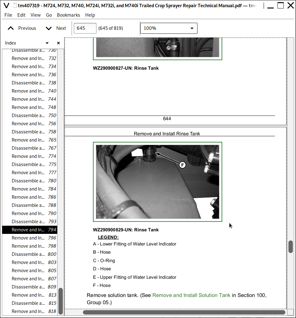
Remove and Install Rinse Tank
Remove and Install Rinse Tank Breather Vent
Remove and Install Rinse Tank Quick Coupler Assembly
Group 15: Hand Wash Tank
Remove and Install Hand Wash Tank
Remove and Install Hand Wash Tank Bleed Valve
Group 20: Polyethylene Tank Repair
Essential or Recommended Tools
Repair Polyethylene Plastic
Install RIVNUT Threaded Inserts
Section 110: Pump
Group 05: Pump
Specifications
Remove and Install Pump
Disassemble and Assemble Piston Diaphragm Pump
Remove and Install Pump Oil Seal
Disassemble and Assemble Pump Accumulator
Remove and Install Hydraulic Motor Drive
Hydraulic Motor Drive Operation and Adjustments
Section 120: Lines and Valves
Group 05: Spray Line
Remove and Install Spray Line Valve
Disassemble and Assemble Spray Line Valve
Section 130: Activation Systems
Group 05: Flow Meter
Remove and Install Flow Meter
Disassemble and Assemble Flow Meter
Group 10: Ball Valves
Remove and Install Protective Cap on Left-Hand Side
Remove and Install External Pump Filling Control Valve
Disassemble and Assemble External Pump Filling Control Valve
Remove and Install Pressure Selection Valve
Disassemble and Assemble Pressure Selection Valve
Remove and Install Suction Valve
Disassemble and Assemble Suction Valve
Remove and Install Injector Shut-Off Valve
Disassemble and Assemble Injector Shut-Off Valve
Remove and Install Ring Line Tank/Pump Selector Valve
Disassemble and Assemble Ring Line Tank/Pump Selector Valve
Group 15: Regulating Unit
Remove and Install Primary Pressure Regulator
Disassemble and Assemble Primary Pressure Regulator
Remove and Install Pressure Regulator
Disassemble and Assemble Pressure Regulator
Remove and Install Suction Filter
Remove and Install Pressure Filter
Remove and Install Tank/Pump Selector Valve
Disassemble and Assemble Tank/Pump Selector Valve
Section 140: Spray Nozzles
Group 05: Spray Nozzles
Remove and Install Nozzle Holder (5-Way)
Disassemble and Assemble Nozzle Holder (5-Way)
Remove and Install Nozzle Holder (Single)
Disassemble and Assemble Nozzle Holder (Single)
Remove and Install Spray Nozzle Solenoid
John Deere Trailed Crop Sprayers M724, M732, M740, M732i, M740i Repair Service Manual (TM407319)
![]()