
John Deere 4630 Self-Propelled Sprayers Repair Service Manual (TM106119)
Complete service repair manual for John Deere 4630 Self-Propelled Sprayers (PIN Prefix 1YH), with all the service information to maintain, repair, and rebuild like professional mechanics.
John Deere 4630 Self-Propelled Sprayers workshop service & repair manual includes:
* Numbered table of contents easy to use so that you can find the information you need fast.
* Detailed sub-steps expand on repair procedure information
* Numbered instructions guide you through every repair procedure step by step.
* Notes, cautions and warnings throughout each chapter pinpoint critical information.
* Bold figure number help you quickly match illustrations with instructions.
* Detailed illustrations, drawings and photos guide you through every procedure.
* Enlarged inset helps you identify and examine parts in detail.
TM106119 - John Deere Self-Propelled Sprayers 4630 Technical Manual (Repair).PDF
TM106119 - John Deere Self-Propelled Sprayers 4630 Technical Manual (Repair).epub
Total Pages: 1,016 pages
File Format: PDF/EPUB/MOBI/AZW (PC/Mac/Android/Kindle/iPhone/iPad; bookmarked, ToC, Searchable, Printable)
Language: English
MAIN SECTIONS
Foreword
General Information
Safety
General Information
Fuels and Lubricants
Engine
Remove and Install Components
Engine Cooling System
Fuel and Air
Remove and Install Components
Diesel Fuel System
Electrical
Batteries
Connector Repair
Charging Circuit
Starting Circuit
Fuses and Relays
Lighting
Chassis Control System
Engine Control System
Spray Rate Control System
Boom Control System
Cab Components
Wiring Harness Routing
Power Train Repair
Remove and Install Hydrostatic Components
Hydrostatic Drive Repair
Planetary Hub Repair
Steering and Brakes
Component Removal and Installation
Steering Column
Steering Valve
Steering Cylinder
Service Brakes
Suspension and Tread Adjust
Component Removal and Installation
Tread Adjust Valves
Tread Adjust Cylinders
Hydraulic System
Component Removal and Installation
Hydraulic Pump
Hydraulic Valves
Boom Hydraulic Cylinders
Hydraulic Oil Cooler
Hydraulic Reservoir
Accumulator
Retractable Ladder
Solution Spray System
Component Removal and Installation
Nozzle Repair
Solution Tank
Solution Pump
Solution Control Valves
Rinse Tank
Eductor
Flow Meter
Foam Marker System
Component Removal and Installation
Foam Marker System Repair
On Board Air System
Operator Station
Cab Component Removal and Installation
Armrest
Air Conditioning System
Heating System
Air Suspension Seat
Cab Door and Windshield
Boom Repair
Component Removal and Installation
Special Tools
Dealer-Fabricated Tools
tm106119 - 4630 Self-Propelled Sprayer Repair
Table of Contents
Foreword
Section 10: General Information
Group 05: Safety
Recognize Safety Information
Understand Signal Words
Perform Service Safely
Wait Before Opening High-Pressure Fuel System
Service Accumulator Systems Safely
Park Machine Safely
Handle Fluids Safely—Avoid Fires
Prevent Battery Explosions
Prepare for Emergencies
Prevent Acid Burns
Wear Protective Clothing
Handle Agricultural Chemicals Safely
Service and Operate Chemical Sprayers Safely
Avoid Contact with Agricultural Chemicals
Clean Vehicle of Hazardous Pesticides
Decontaminate Spray Equipment
Support Machine Properly
Service Machines Safely
Practice Safe Maintenance
Avoid Harmful Asbestos Dust
Work In Ventilated Area
Work in Clean Area
Remove Paint Before Welding or Heating
Avoid Heating Near Pressurized Fluid Lines
Avoid High-Pressure Fluids
Service Tires Safely
Service Cooling System Safely
Illuminate Work Area Safely
Replace Safety Signs
Use Proper Lifting Equipment
Use Proper Tools
Construct Dealer-Made Tools Safely
Decommissioning — Proper Recycling and Disposal of Fluids and Components
Servicing Electronic Control Units
Welding Near Electronic Control Units
Keep Electronic Control Unit Connectors Clean
Handle Electronic Components and Brackets Safely
Live With Safety
Group 10: General Information
Machine Specification
Dimensions
Dimensions—All Machines
Identification Numbers
Sealants and Adhesives Cross-Reference Chart
Face Seal Fittings Assembly and Installation—All Pressure Applications
Metric Face Seal and O-Ring Stud End Fitting Torque Chart—Standard Pressures
Metric Face Seal and O-Ring Stud End Fitting Torque Chart—High Pressure Applications
SAE Face Seal and O-Ring Stud End Fitting Torque Chart—Standard Pressures
SAE Face Seal and O-Ring Stud End Fitting Torque Chart—High Pressure Applications
Four Bolt Flange Fittings Assembly and Installation—All Pressure Applications
SAE Four Bolt Flange Cap Screw Torque Values—Standard Pressure Applications
SAE Four Bolt Flange Cap Screw Torque Values—High Pressure Applications
External Hexagon Port Plug Torque Chart
Identifying Zinc-Flake Coated Fasteners
Metric Bolt and Screw Torque Values
Unified Inch Bolt and Screw Torque Values
Glossary of Terms
Programming Control Units
Preparing and Painting Sprayer Components
Group 15: Fuels and Lubricants
Diesel Fuel
Lubricity of Diesel Fuel
Diesel Engine Coolant (engine with wet sleeve cylinder liners)
Operating in Warm Temperature Climates
John Deere COOL-GARD™ II Coolant Extender
Water Quality for Mixing with Coolant Concentrate
Testing Coolant Freeze Point
Hydrostatic/Hydraulic Drive Oil
Planetary Hub Oil
Grease
Suspension and Steering Grease
Lubricant Storage
Diesel Engine Break-In Oil — Non-Emissions Certified and Certified Tier 1, Tier 2, Tier 3, Stage I, Stage II, and Stage III
Diesel Engine Oil — Tier 3 and Stage III
Section 20: Engine
Group 00: Remove and Install Components
Other Material
Specifications
John Deere Engine Repair—Use CTM
Remove and Install Engine
Remove and Install Hood
Remove and Install Exhaust System
Group 05: Engine Cooling System
Specifications
Fan Belt Routing
Relieving Tension on the Drive Belt
Change the Drive Belt
Drain, Flush, and Fill Cooling System
Test Radiator and Coolant Tank Cap
Section 30: Fuel and Air
Group 00: Remove and Install Components
Specifications
Remove and Install Fuel Tank
Remove and Install Air Cleaner Housing
Remove and Install Radiator
Remove and Install Aftercooler
Remove and Install Fan Drive and Shroud
Remove and Install Air Conditioning Condenser
Remove and Install Fuel Cooler
Remove and Install Recovery Tank
Group 05: Diesel Fuel System
Specifications
Clean and Inspect Fuel Tank
Replace Fuel Filter, Fuel Pump, and Bleed Fuel System
Section 40: Electrical
Group 05: Batteries
Specifications
Battery Safety
Prevent Damage to Electrical Systems
Checking Electrolyte Specific Gravity
Charging Batteries
Connecting Battery Cables
Battery Replacement
Group 10: Connector Repair
Using High-Pressure Washers
Connector Information
Repair Procedure R-A
Repair Procedure R-B
Repair Procedure R-C
Repair Procedure R-D
Repair Procedure R-E
Repair Procedure R-F
Repair Procedure R-G
Repair Procedure R-I
Repair Procedure R-J
Repair Procedure R-K
Repair Procedure R-M
Repair Procedure R-N
Repair Procedure R-AE
Repair Procedure R-AF
Repair Procedure R-AG
Repair Procedure R-AH
Repair Procedure R-AI
Repair Procedure R-AJ
Repair Procedure R-AK
Group 15: Charging Circuit
Specifications
Remove and Install Alternator
Group 20: Starting Circuit
Specifications
Remove and Install Starter Motor
Group 25: Fuses and Relays
Disconnect Electrical Circuit
Load Center Fuses
Load Center Relays and Diodes
Fuses and Relays in the Engine Compartment
Group 30: Lighting
Replace and Adjust Field Lights
Safety Rules When Replacing Halogen Bulbs
Hood Headlight Bulb Replacement and Adjustment
Remove and Install Headlight Assembly
Group 35: Chassis Control System
Specifications
Replace Radar Sensor
Replace Hydraulic Oil Temperature Sensor
Replace Wheel Speed Sensor
Replace Fuel Level Sender
Group 40: Engine Control System
Other Material
Specifications
Replace ECU (Engine Control Unit)
Replace Engine Crankshaft Position Sensor
Replace Engine Oil Pressure Sensor
Replace Engine Fuel Temperature Sensor
Replace Engine Manifold Air Temperature Sensor
Replace Engine Pump Position Sensor
Replace Water-In-Fuel Sensor
Replace Fuel Rail Pressure Sensor
Replace Engine Coolant Temperature Sensor
Replace Air Filter Restriction Switch
Group 45: Spray Rate Control System
Other Material
Specifications
Replace CCU-SRC (Chassis Control Unit - Spray Rate Control Unit)
Replace Solution Pressure Sensor
Group 50: Boom Control System
Replace Boom Height Sensor
Replace Boom Fold/Level Switch
Remove and Install Boom Trac Pro™ Center Section Sensor
Remove and Install Boom Trac Pro™ Inner and Outer Boom Sensors
Replace Boom Level Sensor
Replace Boom Fold Cylinder Switch
Group 55: Cab Components
Other Material
Specifications
Replace Side Console Switches
Replace Side Console Rotary Switch
Replace Boom Fold-Level Switch
Replace Key Switch
Replace Light Switch
Replace Turn Signal Switch
Replace Horn Switch
Replace Wiper Control Switch
Remove and Install Propulsion Control Harness
Remove and Install Throttle Control
Remove and Install Throttle Sensor
Remove and Install Armrest Rocker Switches
Remove and Install Armrest Toggle Switches
Replace Air Conditioning System On/Off Switch
Replace Air Conditioning Temperature Control Switch
Replace Blower Control Switch
Replace Dome Light
Replace Door Switch
Replace Air Conditioning High/Low Pressure Switch
Replace Wiper Motor
Replace Windshield Washer Pump
Replace Seat Air Compressor Motor
Remove and Install Radio
Replace Speakers
Replace Antenna
Replace SSU (Steering System Control Unit)
Group 60: Wiring Harness Routing
Engine Harness Routing
Cab Harness Routing
Chassis Harness Routing
Boom Center Harness Routing
Boom Wing Harness Routing
Guidance Harness Routing
Section 50: Power Train Repair
Group 00: Remove and Install Hydrostatic Components
Essential or Recommended Tools
Other Material
Specifications
Remove and Install Hydrostatic Drive Pump
Replace Hydrostatic Drive Pump Isolators
Remove, Install, and Adjust Hydrostatic Control Cable
Remove and Install Control Valve Neutral Start Switch
Remove and Install Hydrostatic Drive Motor
Remove and Install Drive Shaft
Remove and Install Planetary Hub
Drain and Fill Planetary Hub
Group 05: Hydrostatic Drive Repair
Essential or Recommended Tools
Other Material
Specifications
Emergency Tow Procedure
Start-Up Procedure After Hydrostatic Repair
Start-Up Procedure After Oil Change or Filter Change
Flushing Hydrostatic Drive System
Remove and Install Hydrostatic Pump Control Valve
Tightening Wheel Hardware
Remove and Install Hydrostatic Pump Shaft Seal
Replace Hydrostatic Pump Cartridge Valves
Replace Hydrostatic Pump Charge Pressure Relief Valve
Repair Charge Pump
Adjust Neutral Start Switch
Adjust Control Valve Eccentric Plug
Disassemble Hydrostatic Drive Pump
Inspect and Repair Hydrostatic Drive Pump
Assemble Hydrostatic Drive Pump
Group 15: Planetary Hub Repair
Essential or Recommended Tools
Specifications
Planetary Hub—Exploded View
Disassemble Planetary Hub
Assemble Planetary Hub
Section 60: Steering and Brakes
Group 00: Component Removal and Installation
Other Material
Service Parts Kit
Specifications
Remove and Install Steering Wheel
Remove and Install Steering Column
Remove and Install Steering Valve
Remove and Install AutoTrac™ Steering Valve
Remove and Install Steering Input Device (SID) Sensor
Remove and Install Steering Cylinder (Wide Machine)
Remove and Install Steering Cylinder (Narrow Machine)
Remove and Install AutoTracTM SSU Control Unit
Remove and Install AutoTracTM Steering Electrohydraulic Control Valve
Remove and Install AutoTracTM Wheel Angle Sensor
Remove and Install Service Brake Valve
Remove and Install Service Brake Caliper
Group 05: Steering Column
Specifications
Bleed Steering System
Group 10: Steering Valve
Specifications
Service Parts Kit
Repair Steering Valve
Group 15: Steering Cylinder
Service Parts Kit
Specifications
Repair Steering Cylinder (Wide Machine)
Repair Steering Cylinder (Narrow Machine)
Check Front Axle Toe-In
Adjusting Front Axle Toe-In (Wide Machine)
Adjusting Front Axle Toe-In (Narrow Machine)
Group 20: Service Brakes
Other Material
Service Parts Kits
Specifications
Inspect Service Brake System Components
Disassemble and Assemble Service Brake Caliper
Start-Up Procedure After Brake System Repair
Section 61: Suspension and Tread Adjust
Group 00: Component Removal and Installation
Other Material
Specifications
Remove and Install Air Spring Leveling System Control Valve
Remove and Install Leveling System Unloader Valve Switch
Remove and Install Front and Rear Air Spring Assemblies
Remove and Install Air Spring Upper Mount
Remove and Install Air Spring Leveling System Linkage
Remove and Install Tread Adjust Valve Block
Remove and Install Hydraulic Tread Adjust Cylinders
Remove and Install Top Tread Adjust Shim Pads
Remove and Install Bottom Tread Adjust Shim Pads
Replace Suspension Bushings and Seals
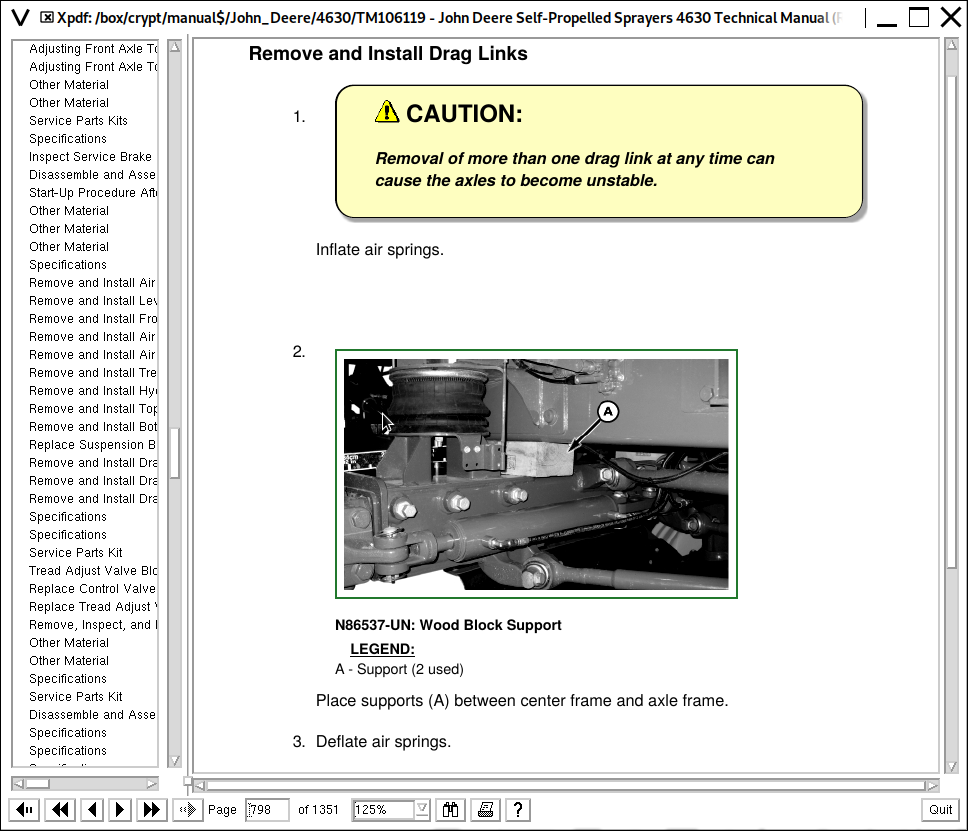
Remove and Install Drag Links
Remove and Install Drag Link Casting (Front)
Remove and Install Drag Link Casting (Rear)
Group 05: Tread Adjust Valves
Specifications
Service Parts Kit
Tread Adjust Valve Block
Replace Control Valve Coil(s)
Replace Tread Adjust Valve
Remove, Inspect, and Install Manifold Check Valve and Pilot Piston
Group 10: Tread Adjust Cylinders
Other Material
Specifications
Service Parts Kit
Disassemble and Assemble Tread Adjust Cylinders
Section 70: Hydraulic System
Group 00: Component Removal and Installation
Specifications
Remove and Install Hydraulic Oil Cooler
Remove and Install Hydraulic Pump
Remove and Install Hydraulic Pump Compensator
Remove and Install Boom Control Valve
Remove and Install Boom Lift Cylinder
Remove and Install Boom Leveling Cylinder
Remove and Install Boom Inner Fold Cylinder
Remove and Install Boom Outer Fold Cylinder
Remove and Install Priority Valve
Remove and Install Combination Valve
Remove and Install Traction Control Valve
Remove and Install Shift Valve
Remove and Install Hydraulic Reservoir
Remove and Install Accumulator
Remove and Install Attenuator
Remove and Install Ladder Cylinder
Group 05: Hydraulic Pump
Service Parts Kit
Specifications
Relieve Hydraulic System Pressure
Disassemble and Assemble Hydraulic Pump
Repair Hydraulic Pump Compensator
Group 10: Hydraulic Valves
Other Material
Service Parts Kit
Specifications
Boom Valve Assembly
Boom Control Valve General Information
Disassemble, Inspect, and Assemble Boom Control Valve
Disassemble, Inspect, and Assemble Priority Valve
Repair Combination Valve
Repair Traction Control Valve
Repair Shift Valve
Group 15: Boom Hydraulic Cylinders
Other Material
Specifications
Service Parts Kit
Hydraulic Cylinder and Boom Control Valve Fitting Torques
Adjust Boom Stop Bolts
Adjusting Boom Outer Fold Cylinder
Disassemble and Assemble Boom Lift Cylinder
Disassemble and Assemble Boom Leveling Cylinder
Disassemble and Assemble Boom Inner Fold Cylinder
Disassemble and Assemble Boom Outer Fold Cylinder
Group 20: Hydraulic Oil Cooler
Specifications
Leak Test Hydraulic Oil Cooler
Group 25: Hydraulic Reservoir
Specifications
Clean Hydraulic Reservoir Strainers
Group 30: Accumulator
Specifications
Charge Accumulator
Group 35: Retractable Ladder
Other Material
Service Parts Kit
Disassemble and Assemble Retractable Ladder Cylinder
Section 80: Solution Spray System
Group 00: Component Removal and Installation
Other Material
Specifications
Remove and Install Solution Tank
Remove and Install Agitation Nozzles
Remove Solution Pump and Motor
Install Solution Pump and Motor
Remove and Install Flowmeter Assembly
Remove and Install Flowmeter Sensor
Remove and Install Boom Section Shut-Off Valves
Replace Boom Section Shut-Off Valve Actuator
Remove and Install Rinse Tank
Remove and Install Eductor System Venturi
Remove and Install AutoTrac™ Vision Sensor
Remove and Install AutoTrac™ RowSense™ Sensor
Group 05: Nozzle Repair
Cleaning SprayMaster™ 5-Position Nozzle Bodies—Standard Flow
Cleaning SprayMater™ 5-Position Nozzle Bodies—High Flow
Group 10: Solution Tank
Other Material
Specifications
Flush Solution Tank and Spray System
Group 15: Solution Pump
Service Equipment and Tools
Other Material
Specifications
Repair Solution Pump
Repair Solution Pump Hydraulic Motor
Group 20: Solution Control Valves
Other Material
Specifications
Disassemble and Assemble Fittings
Repair Check Valves and Strainers
Replace Solution Control Valves
Group 25: Rinse Tank
Repair Polyethylene Plastic
Group 30: Eductor
Eductor Assembly
Group 35: Flow Meter
Replace Flowmeter Insert
Recondition Flowmeter
Calibrate Flowmeter
Section 81: Foam Marker System
Group 00: Component Removal and Installation
Specifications
Other Material
Remove and Install Foam Marker Concentrate Tank
Remove and Install Control Box (With On Board Air)
Remove and Install Control Box (With 12-volt Compressor)
Remove and Install On Board Air Compressor
Remove and Install On Board Air Dryer
Replace Foam Mixing Chamber
Group 05: Foam Marker System Repair
Other Material
On Board Air (OBA) Foam Marker Schematic
Repair Control Box (With On Board Air)
Foam Marker System (With Internal 12-volt Compressor) Schematic
Repair Control Box (With 12-volt Compressor)
Repair Control Box Solenoid
Repair Foam Marker Tubes
Tube Fittings
Group 10: On Board Air System
Specifications
Service Parts Kit
Repair On Board Air Dryer
Section 90: Operator Station
Group 05: Cab Component Removal and Installation
Replace SSU Control Unit
Replace CCU-SRC Control Unit
Remove, Inspect, and Install Cab Interior Recirculating Air Filters
Remove, Inspect, and Install Exterior Cab Intake Air Filters
Remove and Install Headliner
Remove and Install Fender Console
Remove and Install Cowl
Remove and Install Cab Roof
Remove and Install Cab
Group 10: Armrest
Other Material
Service Parts Kits
Specifications
Remove and Install Armrest
Remove and Install Armrest Control Cover
Remove and Install Multifunction Control Handle
Group 15: Air Conditioning System
Other Material
Service Parts Kits
Specifications
Hose and Tubing O-Ring Connection Torques
System Information
Remove and Install Compressor
Remove and Install Compressor Relief Valve
Replace Receiver Dryer
Remove and Install the Evaporator and Expansion Valve
Discharge Air Conditioning System
Flush Compressor
Flush Evaporator
Flush Evaporator (Through Expansion Valve)
Flush Condenser
Purge Air Conditioning System
Evacuate Air Conditioning System
Charge Air Conditioning System
Check Refrigerant Oil Charge in Compressor
Determine Correct Refrigerant Oil Charge
Leak Test
Disassemble and Assemble Compressor Clutch
Check Clutch Hub Clearance
Inspect Compressor Manifold
Start Up Instructions for Air Conditioning Compressor
Adjust Thermostat Switch Control Cable
Group 20: Heating System
Remove and Install Fan Motor Resistors
Remove and Install Fan Motors
Remove and Install Heater Valve
Remove and Install Heater Core
Adjust Heater Valve Control Cable
Group 25: Air Suspension Seat
Other Material
Service Parts Kits
Remove Seat from Suspension
Remove Air Seat Suspension System
Operator Seat—Exploded View
Operator Seat Air Suspension Assembly—Exploded View
Disassemble and Assemble Operator's Seat Air Suspension Assembly
Group 30: Cab Door and Windshield
Specifications
Remove and Install Windshield
Remove and Install Rear Window
Remove and Install Front Lower Windows
Remove and Install Side Windows
Remove and Install Cab Doors
Remove and Install Safety Exit Door
Door Latch Installation and Adjustment
Section 100: Boom Repair
Group 00: Component Removal and Installation
Specifications
Remove and Install Boom Shock Absorbers
Remove and Install Boom Wear Plates and Plastic Sleeves
Remove and Install Boom Roll Suspension Springs
Remove and Install Boom Center Roll Bushings
Remove and Install Boom Inner Wing Leveling Bushings
Remove and Install Boom Inner Wing Fold Bushings
Remove and Install Boom Inner Wing Leveling Cylinder Bushings
Remove and Install Boom Inner Wing Fold Cylinder Bushings
Section 199: Special Tools
Group 05: Dealer-Fabricated Tools
DFN20 Solution Pump Seal Driver
DFN21 Pump Support Fixture
DFN22 Bearing Seat Driver
DFRW20—Compressor Holding Fixture
DFNX65-A1 Eccentric Plug Adjustment Tool
DFNX65-A2 Sizing Arbor
DFNXT2—Agitation Nozzle Tool
DFNXT11 Pump Removal Tool
DFNXT15 Planetary Assembly Spacer
John Deere 4630 Self-Propelled Sprayers Repair Service Manual (TM106119)
![]()