
John Deere Self-Propelled Sprayer 4710 Operation and Tests Service Manual (TM2108)
Complete Diagnostics and Tests Service Manual with electrical wiring diagrams for John Deere Self-Propelled Sprayer 4710 (SN: 004001 - XXXXXX), with workshop information to maintain, diagnose, and rebuild like professional mechanics.
John Deere Self-Propelled Sprayer 4710 workshop Operation and Test manual includes:
* Numbered table of contents easy to use so that you can find the information you need fast.
* Detailed sub-steps expand on repair procedure information
* Numbered instructions guide you through every repair procedure step by step.
* Troubleshooting and electrical service procedures are combined with detailed wiring diagrams for ease of use.
* Notes, cautions and warnings throughout each chapter pinpoint critical information.
* Bold figure number help you quickly match illustrations with instructions.
* Detailed illustrations, drawings and photos guide you through every procedure.
* Enlarged inset helps you identify and examine parts in detail.
TM2108 - John Deere Self-Propelled Sprayer 4710 Technical Manual - Operation and Test.PDF
TM2108 - John Deere Self-Propelled Sprayer 4710 Technical Manual - Operation and Test.EPUB
Total Pages: 2,362 pages
File Format: PDF/EPUB/MOBI/AZW (PC/Mac/Android/Kindle/iPhone/iPad; bookmarked, ToC, Searchable, Printable)
Language: English
MAIN SECTIONS
Diagnostic Trouble Codes
Fault Codes
SSU - Steering System Diagnostic Trouble Codes
4710 Self Propelled Sprayer Symptoms
Engine
Fuel/Air
Electrical
Power Train
Brakes
Hydraulics
Suspension and Tread Adjust
Steering
Operator Station
Solution System
Foam Marker
Engine Diagnosis and Test
Fuel and Air Diagnosis and Tests
Electrical Diagnosis and Tests
Agitation Diagnostics
Air Quality Diagnostics
Auxiliary Power Diagnostics
Caution Light Diagnostics
CCU/SRC Controller Diagnostics
Charging Diagnostics
Dome and Sentry Light Diagnostics
Engine Air Filter Switch Diagnostics
Engine Coolant Sensor Diagnostics
Engine Oil Pressure Switch Diagnostics
Engine Speed Sensor Diagnostics
Foam Marker (Dual Drop) Diagnostics
Foam Marker (Single Drop) Diagnostics
Fuel Level Sensor Diagnostics
Fuel Shut-Off Diagnostics
Horn Diagnostics
Hydraulic Oil Temperature Sensor Diagnostics
Hydrostatic Boost Diagnostics
Ladder w/ Remote Control Diagnostics
Ladder w/o Remote Control Diagnostics
Lighter Diagnostics
Lighting Diagnostics
Load Sense Jam Valve Diagnostics
Park Brake Diagnostics
Power Diagnostics
Radar Sensor Diagnostics
Radio and Clock Diagnostics
Seat Adjust Diagnostics
Solution Pressure Diagnostics
Solution Pump Diagnostics
Speed Range Diagnostics
Spray Control Diagnostics
Spray Rate Diagnostics
Start Aid Diagnostics
Starting System Diagnostics
Stop Light Diagnostics
Throttle Diagnostics
Traction Control Diagnostics
Tread Adjust Diagnostics
Wheel Speed Sensor Diagnostics
Wiper Diagnostics
Connector Information (end views, numbers, location photos)
Power Train Diagnosis and Tests
Brake Systems Diagnosis and Tests
Hydraulic System Diagnosis and Tests
Suspension and Tread Adjust Diagnosis and Tests
Steering System Diagnosis and Tests
Operator Station Diagnosis and Tests
Air Conditioning and Heating Diagnostics
Component Location
Solution System Diagnosis and Tests
Foam Marker Diagnosis and Tests
tm2108 - 4710 Self-Propelled Sprayer Diagnosis and Tests
Table of Contents
Foreword
Section 210: General Information
Group 05: Safety
Recognize Safety Information
Understand Signal Words
Follow Safety Instructions
Prevent Machine Runaway
Use Seat Belt Properly
Operate Safely
Beware of Exhaust Fumes
Keep Riders Off Machine
Protect Against Noise
Avoid Heating Near Pressurized Fluid Lines
Handle Fluids Safely—Avoid Fires
Battery Safety
Prevent Battery Explosions
Handle Chemical Products Safely
Avoid Contact with Chemicals, Including Pesticides
Clean Vehicle of Hazardous Chemicals, Including Pesticides
Prepare for Emergencies
Prevent Acid Burns
Avoid High-Pressure Fluids
Park Machine Safely
Support Machine Properly
Wear Protective Clothing
Work In Clean Area
Service Machines Safely
Work In Ventilated Area
Illuminate Work Area Safely
Replace Safety Signs
Use Proper Lifting Equipment
Remove Paint Before Welding or Heating
Avoid Heating Near Pressurized Fluid Lines
Service Tires Safely
Avoid Harmful Asbestos Dust
Use Proper Tools
Construct Dealer-Made Tools Safely
Dispose of Waste Properly
Live With Safety
Group 10: Machine Specifications
Metric Bolt and Cap Screw Torque Values
Unified Inch Bolt and Cap Screw Torque Values
High Pressure Face Seal Torque Chart
Service Recommendations for Flat Face O-Ring Seal Fittings
Machine Specification
Dimensions—18.3 m (60 ft) Boom
Dimensions—24.4 m and 27.4 m (80 and 90 ft) Boom
Dimensions—All Machines
Group 15: Operational Checks
Before You Start
Operational Checks
Group 20: Machine Component Location
Identification Numbers
Section 211: Diagnostic Trouble Codes
Group 1: Fault Codes
Fault Code 20 - Disconnected Monitor or Controller
Fault Code 21 - Display Conflict
Fault Code 30 - Too Many Monitors
Fault Code 31 - Display Communications Overload
Fault Code 33 - Display Memory Failure
Fault Code 40 - No GPS Communications
Fault Code 41 - No GPS Differential
Fault Code 42 - GPS Low License
Fault Code 43 - GPS Invalid License
Fault Code 44 - No KeyCard
Fault Code 45 - GPS is Lost
Fault Code 46 - No GPS
Fault Code 47 - Warning - Primary to Auxiliary
Fault Code 48 - Warning - CAN Bus Voltage
Fault Code 49 - Warning - Primary Display
Fault Code 110 - CAN Bus Wiring
Fault Code 112 - Display Conflict
Fault Code 113 - Incompatible Monitor
Group 2: SSU - Steering System Diagnostic Trouble Codes
SSU 000162.09 - Speed Range
SSU 000168.03 - Battery Voltage High
SSU 000168.04 - Battery Voltage Low
SSU 000517.09 - GPS Speed
SSU 000630.13 - AutoTrac Not Calibrated
SSU 001079.03 - Sensor Voltage High
SSU 001079.04 - Sensor Voltage Low
SSU 001504.07 - Seat Switch
SSU 001504.14 - Operator Out Of Seat
SSU 001638.09 - Oil Temperature
SSU 001807.02 - Steering Input Device (SID) Inverted
SSU 001807.03 - Steering Input Device (SID) 1 Voltage High
SSU 001807.04 - Steering Input Device (SID) 1 Voltage Low
SSU 001807.05 - Steering Input Device (SID) 1 Current Low
SSU 001807.06 - Steering Input Device (SID) 1 Current High
SSU 001807.10 - Steering Input Device (SID) 1
SSU 001807.14 - Steering Input Device (SID) 1
SSU 522273.00 - EH Valve Command High
SSU 522273.01 - EH Valve Command Low
SSU 522387.07 - No Motion On WAS
SSU 522394.09 - TCM Status
SSU 523698.09 - GSD Status
SSU 523766.02 - Invalid Activation Code
SSU 523767.02 - Resume Switch
SSU 523795.02 - EH Valve Inverted
SSU 523795.07 - Low Motion On Wheel Angle Sensor (WAS)
SSU 523795.10 - EH Valve Failure
SSU 523795.12 - EH Valve
SSU 523795.13 - EH Valve Deadband
SSU 523810.01 - Valve Power
SSU 523821.02 - Machine ID Mismatch
SSU 523824.03 - Steering Input Device (SID) 2 Voltage High
SSU 523824.04 - Steering Input Device (SID) 2 Voltage Low
SSU 523824.05 - Steering Input Device (SID) 2 Current Low
SSU 523824.06 - Steering Input Device (SID) 2 Current High
SSU 523824.10 - Steering Input Device (SID) 2
SSU 523824.14 - Steering Input Device (SID) 2
SSU 523826.00 - Wheel Angle Sensor (WAS) High
SSU 523826.01 - Wheel Angle Sensor (WAS) Low
SSU 523826.02 - Wheel Angle Sensor (WAS) Inverted
SSU 523826.07 - Wheel Angle Sensor (WAS) Range
SSU 523826.10 - Wheel Angle Sensor (WAS) Motion
Section 212: 4710 Self Propelled Sprayer Symptoms
Group 220: Engine
Engine Diagnostics
Group 230: Fuel/Air
Air Intake System Diagnostics
Fuel System Diagnostics
Group 240: Electrical
Agitation Diagnostics
Air Quality Diagnostics
Auxiliary Power Diagnostics
Boom Left Hand Leveling Diagnostics (60 ft)
Boom Left Hand Leveling Diagnostics (80/90 ft)
Boom Raise/Lower Diagnostics (60 ft)
Boom Raise/Lower Diagnostics (80/90 ft)
Boom Right Hand Leveling Diagnostics (60 ft)
Boom Right Hand Leveling Diagnostics (80/90 ft)
Boom Roll/Bias Diagnostics (80/90 ft)
Boom Unfold and Fold Diagnostics (60 ft)
Boom Unfold and Fold Diagnostics (80/90 ft)
CAN Bus Diagnostics
Caution Light Diagnostics
CCU/SRC Controller Diagnostics
Charging Diagnostics
Dome and Sentry Light Diagnostics
Engine Air Filter Switch Diagnostics
Engine Coolant Sensor Diagnostics
Engine Oil Pressure Switch Diagnostics
Engine Speed Sensor Diagnostics
Foam Marker (Dual Drop) Diagnostics
Foam Marker (Single Drop) Diagnostics
Fuel Level Sensor Diagnostics
Fuel Shut-Off Diagnostics
GREENSTAR AutoTrac Diagnostics
GREENSTAR Display Diagnostics
GREENSTAR FIELD DOC Diagnostics
GREENSTAR KeyCard and PC Data Storage Card Diagnostics
GREENSTAR GPS Receiver - L-Band Diagnostics
GREENSTAR GPS Receiver - STARFIRE Diagnostics without Terrain Compensation Module
GREENSTAR GPS Receiver - STARFIRE Diagnostics with Terrain Compensation Module
GREENSTAR GPS Receiver with Terrain Compensation Module and Real Time Kinematic Radio Diagnostics
GREENSTAR Mobile Processor Diagnostics
GREENSTAR Parallel Tracking Diagnostics
Horn Diagnostics
Hydraulic Oil Temperature Sensor Diagnostics
Hydrostatic Boost Diagnostics
Ladder w/ Remote Control Diagnostics
Ladder w/o Remote Control Diagnostics
Lighter Diagnostics
Lighting Diagnostics
Load Sense Jam Valve Diagnostics
Park Brake Diagnostics
Power Diagnostics
Radar Sensor Diagnostics
Radio and Clock Diagnostics
Seat Adjust Diagnostics
Solution Pressure Diagnostics
Solution Pump Diagnostics
Speed Range Diagnostics
Spray Control Diagnostics
SPRAYSTAR System Diagnostics
Spray Rate Diagnostics
Start Aid Diagnostics
Starting System Diagnostics
Stop Light Diagnostics
Throttle Without Remote Control Diagnostics
Throttle With Remote Control Diagnostics
Traction Control Diagnostics
Tread Adjust Diagnostics
Wheel Speed Sensor Diagnostics
Wiper Diagnostics
Group 250: Power Train
Final Drive Diagnostics
Hydrostatic Drive Diagnostics
Hydrostatic Reverse Boost Diagnostics
Traction Control Diagnostics, Serial Numbers XXXX-6000
Traction Control Diagnostics, Serial Numbers 6001-XXXX
Group 260: Brakes
Park Brake Diagnostics
Service Brakes Diagnostics
Group 270: Hydraulics
Basic Hydraulic System Diagnostics
Boom - Left-Hand Leveling Diagnostics
Boom Raise and Lower Diagnostics
Boom - Right-Hand Leveling Diagnostics
Boom Roll Bias Diagnostics
Boom Unfold/Fold Diagnostics - 18.3 M (60 ft) Boom
Boom Unfold/Fold Diagnostics - 24.4/27.4 M (80/90 ft) Boom
Power Washer Diagnostics
Solution Pump Diagnostics
Group 275: Suspension and Tread Adjust
Tread Adjust Diagnostics
Group 280: Steering
Steering Diagnostics
Group 290: Operator Station
Air Conditioning and Heating Diagnostics
Group 300: Solution System
SPRAYSTAR SPRAYSTAR is a trademark of Deere & Company Solution Control System
Group 310: Foam Marker
12 V Compressor Diagnosis
On Board Air Diagnosis
Section 220: Engine Diagnosis and Test
Group 05: General Information
General Information
Group 10: Test Procedures and Adjustments
Test Procedures and Adjustments
Group 15: Engine Diagnostic Information
Theory of Operation
Engine Operational Checks
Group 20: Component Location
Engine Component Location
Section 230: Fuel and Air Diagnosis and Tests
Group 05: General Information
General Information
Group 10: Tests Procedures and Adjustments
Tests and Adjustments
Group 15A: Air Intake System Diagnostics
Theory of Operation
Air Intake Diagnostics
Group 15B: Fuel System Diagnostics
Detailed Description
Schematic
Fuel System Diagnostics
Group 20: Component Location
Component Location
Section 240: Electrical Diagnosis and Tests
Group 5: How to Use Diagnostic Information
How to Use the Electrical Diagnostic Section
Group 10: Component Identification
Component Identification Legend
Group 15A: Agitation Diagnostics
Theory of Operation
Agitation Schematic
Agitation Diagnostics
Group 15B: Air Quality Diagnostics
Theory of Operation
Air Quality Schematic
Air Quality Diagnostics
Group 15C: Auxiliary Power Diagnostics
Theory of Operation
Auxiliary Power Schematic
Auxiliary Power Diagnostics
Group 15D: Boom Left Hand Leveling Diagnostics (60 ft)
Theory of Operation
Left Boom Fold Schematic
Left Boom Leveling Diagnostics
Group 15E: Boom Left Hand Leveling Diagnostics (80/90 ft)
Theory of Operation
Left Boom Leveling Schematic (80/90 ft)
Left Boom Leveling Diagnostics (80/90 ft)
Group 15F: Boom Raise/Lower Diagnostics (60 ft)
Theory of Operation
Boom Fold/Raise-Lower Schematic (60 ft)
Boom (60 ft) - Raise/Lower Diagnostics
Group 15G: Boom Raise/Lower Diagnostics (80/90 ft)
Theory of Operation
Boom - Raise/Lower Schematic
Boom - Raise/Lower Diagnostics
Group 15H: Boom Right Hand Leveling Diagnostics (60 ft)
Theory of Operation
Right Boom Fold Schematic
Right Boom Leveling Diagnostics
Group 15I: Boom Right Hand Leveling Diagnostics (80/90 ft)
Theory of Operation
Right Boom Leveling Schematic
Right Boom Leveling Diagnostics
Group 15J: Boom Roll/Bias Diagnostics (80/90 ft)
Theory of Operation
Boom Raise/Lower and Roll Bias Schematic
Boom Roll/Bias Diagnostics
Group 15K: Boom Unfold and Fold Diagnostics (60 ft)
Theory of Operation
Boom Fold Schematic
Boom Fold Diagnostics
Group 15L: Boom Unfold and Fold Diagnostics (80/90 ft)
Theory of Operation
Boom Fold Schematics
Boom Unfold and Fold Diagnostics
Group 15M: CAN Bus Diagnostics
Theory of Operation
Schematics
CAN Bus Diagnostics
Group 15N: Caution Light Diagnostics
Theory of Operation
Caution Light Schematic
Caution Light Diagnostics
Group 15O: CCU/SRC Controller Diagnostics
Theory of Operation
CCU/SRC Schematic
CCU/SRC Controller Diagnostics
Group 15P: Charging Diagnostics
Theory of Operation
Charging System Schematic
Charging System Diagnostics
Temperature Correction Chart
Group 15Q: Dome and Sentry Light Diagnostics
Theory of Operation
Dome and Sentry Lamp Schematic
Voltage Checks
Group 15R: Engine Air Filter Switch Diagnostics
Theory of Operation
Engine Air Filter Switch Schematic
Engine Air Filter Switch Diagnostics
Group 15S: Engine Coolant Sensor Diagnostics
Theory of Operation
Engine Coolant Sensor Schematic
Engine Coolant Sensor Diagnostics
Group 15T: Engine Oil Pressure Switch Diagnostics
Theory of Operation
Engine Oil Pressure Switch Schematic
Engine Oil Pressure Switch Diagnostics
Group 15U: Engine Speed Sensor Diagnostics
Theory of Operation
Engine Speed Sensor Schematic
Engine Speed Sensor Diagnostics
Group 15V: Foam Marker (Dual Drop) Diagnostics
Theory of Operation
Foam Marker (Dual Drop) Schematic
Foamer System Problem Diagnostics
Group 15W: Foam Marker (Single Drop) Diagnostics
Theory of Operation
Foam Marker (Single Drop) Schematic
Foam Marker Single Drop System Diagnostics
Group 15X: Fuel Level Sensor Diagnostics
Theory of Operation
Fuel Level Sensor Schematic
Fuel Level Sensor Diagnostics
Group 15Y: Fuel Shut-Off Diagnostics
Theory of Operation
Fuel Shut-Off Schematic
Fuel Shut-Off Diagnostics
Group 15Z: GREENSTARGREENSTAR is a trademark of Deere & Company AUTOTRACAUTOTRAC is a trademark of Deere & Company Diagnostics
Theory of Operation
GREENSTAR AutoTrac Electrical Schematics
Steering System Check and Calibration Procedure
SSU Diagnostic Trouble Codes
AutoTrac Diagnostics
Group 15AA: GREENSTARGREENSTAR is a trademark of Deere & Company Display Diagnostics
Theory of Operation
Electrical Schematic
Greenstar Display Diagnostic Trouble Codes
GREENSTAR GREENSTAR is a trademark of Deere & Company Display Diagnostics
Group 15AB: GREENSTARGREENSTAR is a trademark of Deere & Company FIELD DOCFIELD DOC is a trademark of Deere & Company Diagnostics
Theory of Operation
Electrical Schematic
FIELD DOC FIELD DOC is a trademark of Deere & Company Diagnostics
Group 15AC: GREENSTARGREENSTAR is a trademark of Deere & Company KeyCard and PC Data Storage Card Diagnostics
Theory of Operation
Electrical Schematic
GREENSTAR GREENSTAR is a trademark of Deere & Company KeyCard and PC Data Storage Card Diagnostics
Group 15AD: GREENSTARGREENSTAR is a trademark of Deere & Company GPS Receiver Identification
STARFIRE STARFIRE is a trademark of Deere & Company GPS Receiver
L-Band GPS Receiver
GPS Position Receiver - With Terrain Compensation Module and Real Time Kinematics Radio
Non—John Deere GPS Receiver
Group 15AE: GREENSTARGREENSTAR is a trademark of Deere & Company GPS Receiver - L-Band Diagnostics
Theory of Operation
Electrical Schematic
GREENSTAR GREENSTAR is a trademark of Deere & Company GPS Receiver - L-Band Diagnostics
Group 15AF: GREENSTARGREENSTAR is a trademark of Deere & Company GPS Receiver STARFIRESTARFIRE is a trademark of Deere & Company without Terrain Compensation Module Diagnostics
Theory of Operation
Electrical Schematic
GREENSTAR GREENSTAR is a trademark of Deere & Company GPS Receiver STARFIRE STARFIRE is a trademark of Deere & Company Diagnostics
Group 15AG: GREENSTARGREENSTAR is a trademark of Deere & Company GPS Receiver STARFIRESTARFIRE is a trademark of Deere & Company with Terrain Compensation Module Diagnostics
Theory of Operation
STARFIRE Receiver with Terrain Compensation Module Electrical Schematic
GREENSTAR Receiver, STARFIRE Receiver with Terrain Compensation Module Diagnostics
Group 15AH: GREENSTARGREENSTAR is a trademark of Deere & Company GPS Receiver STARFIRESTARFIRE is a trademark of Deere & Company with TCM using RTK Diagnostics
Theory of Operation
STARFIRE RTK Receiver Electrical Schematic
STARFIRE Receiver with TCM using RTK Correctional Signal
Group 15AI: GREENSTARGREENSTAR is a trademark of Deere & Company Mobile Processor Diagnostics
Theory of Operation
Electrical Schematic
GREENSTAR GREENSTAR is a trademark of Deere & Company Mobile Processor Diagnostics
Group 15AJ: GREENSTARGREENSTAR is a trademark of Deere & Company Parallel Tracking
Theory of Operation
Electrical Schematic
Parallel Tracking Type A Diagnostics
Group 15AK: Horn Diagnostics
Theory of Operation
Horn Circuit Schematic
Voltage Checks
Group 15AL: Hydraulic Oil Temperature Sensor Diagnostics
Theory of Operation
Hydraulic Oil Temperature
Hydraulic Oil Temperature Sensor Schematic
Hydraulic Oil Temperature Sensor Diagnostics
Group 15AM: Hydrostatic Boost Diagnostics
Theory of Operation
Hydrostatic Boost Schematic
Hydrostatic Boost Diagnostics
Group 15AN: Ladder w/ Remote Control Diagnostics
Theory of Operation
Ladder w/Remote Control Electrical Schematic
Group 15AO: Ladder w/o Remote Control Diagnostics
Theory of Operation
Ladder w/o Remote Control Electrical Schematic
Group 15AP: Lighter Diagnostics
Theory of Operation
Lighter Circuit Schematic
Voltage Checks
Group 15AQ: Lighting Diagnostics
Theory of Operation
Lighting Circuit Operation
V1 - Diode Block
Warning and Turn Signal Lights - 90 Foot Boom Schematic
Warning and Turn Signal Lights - 60 Foot Boom Schematic
Road Lights Schematic
Field 1 and Field 2 Lights Schematic
Group 15AR: Load Sense Jam Valve Diagnostics
Theory of Operation
Load Sense Jam Valve Schematic
Load Sense Jam Valve Diagnostics
Group 15AS: Park Brake Diagnostics
Theory of Operation
Park Brake Schematic
Park Brake Diagnostics
Group 15AT: Power Diagnostics
Theory of Operation
V1- Diode Block
Power System Schematic
Group 15AU: Radar Sensor Diagnostics
Theory of Operation
Radar Sensor Schematic
Radar Sensor Diagnostics
Group 15AV: Radio and Clock Diagnostics
Theory of Operation
Radio and Clock Schematic
Voltage Checks
Group 15AW: Seat Adjust Diagnostics
Theory of Operation
Seat Adjust Schematic
Group 15AX: Solution Pressure Diagnostics
Theory of Operation
Solution Pressure Schematic
Solution Pressure Diagnostics
Group 15AY: Solution Pump Diagnostics
Theory of Operation
Solution Pump Schematic
Solution Pump Diagnostics
Group 15AZ: Speed Range Diagnostics
Theory of Operation
Speed Range Schematic
Speed Range Diagnostics
Group 15BA: Spray Control Diagnostics
Theory of Operation
Spray Control Schematic for 80/90 Foot Boom
Spray Control Schematic for 60 Foot Boom
Spray Control Diagnostics
Group 15BB: SPRAYSTARSPRAYSTAR is a trademark of Deere & Company System Diagnostics
Theory of Operation
SPRAYSTAR SPRAYSTAR is a trademark of Deere & Company System W/O Parallel Tracking Schematic
SPRAYSTAR SPRAYSTAR is a trademark of Deere & Company System Diagnostics
Group 15BC: Spray Rate Diagnostics
Theory of Operation
Spray Rate Schematic
Spray Rate Diagnostics
Group 15BD: Start Aid Diagnostics
Theory of Operation
Start Aid Schematic
Start Aid Diagnostics
Group 15BE: Starting System Diagnostics
Theory of Operation
Starting System Schematic
Starting System Diagnostics
Group 15BF: Stop Light Diagnostics
Theory of Operation
Stop Light Schematic
Stop Light Diagnostics
Group 15BG: Throttle W/O Remote Control Diagnostics
Theory of Operation
Throttle w/o Remote Control Schematic
Group 15BH: Throttle w/Remote Control Diagnostics
Theory of Operation
Throttle w/Remote Control Schematic
Group 15BI: Traction Control Diagnostics
Theory of Operation
Traction Control Schematic
Traction Control Diagnostics
Group 15BJ: Tread Adjust Diagnostics
Theory of Operation
Tread Adjust Schematic
Tread Adjust Diagnostics
Group 15BK: Wheel Speed Sensor Diagnostics
Theory of Operation
Wheel Speed Sensor Schematic
Wheel Speed Sensor Diagnostics
Group 15BL: Wiper Diagnostics
Theory of Operation
Wiper Schematic
Voltage Checks
Group 20: Connector Information (end views, numbers, location photos)
Connector Number Designations
X100 - X199 Connectors
X200 - X299 Connectors
X400 - X499 Connectors
X500 - X599 Connectors
X600 - X699 Connectors
X700 - X799 Connectors
Section 250: Power Train Diagnosis and Tests
Group 05: General Information
General Information
Group 10: Test Procedures and Adjustments
Adjust Hydrostatic Pump Linkage
Adjust Charge Pressure Relief Valve
Adjust Charge Pressure Relief Valve on Front Pump
Adjust Charge Pressure Relief Valve on Rear Pump
Adjust Hydrostatic Forward High Pressure
Adjust Reverse High Pressure (Dual Stage Multi-function Valves)
Test - Hydrostatic Charge Pressure
Test - Neutral Charge Pressure
Test - Forward and Reverse Charge Pressure
Test - Independent Forward and Reverse Charge Pressure
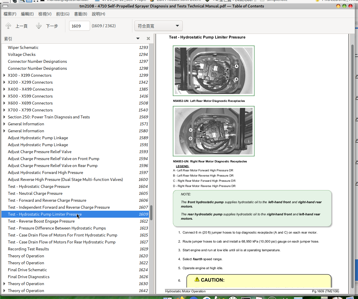
Test - Hydrostatic Pump Limiter Pressure
Test - Reverse Boost Engage Pressure
Test - Pressure Difference Between Hydrostatic Pumps
Test - Case Drain Flow of Motors For Front Hydrostatic Pump
Test - Case Drain Flow of Motors For Rear Hydrostatic Pump
Recording Test Results
Group 15A: Final Drive Diagnostics
Theory of Operation
Final Drive Schematic
Final Drive Diagnostics
Group 15B: Hydrostatic Drive Diagnostics
Theory of Operation
Hydrostatic Drive Schematic
Hydrostatic Drive Diagnostics
Group 15C: Hydrostatic Reverse Boost Diagnostics
Theory of Operation
Hydrostatic Reverse Boost Hydraulic Schematic
Reverse Boost Hydraulic Diagnostics
Group 15D: Traction Control Diagnostics (Serial Numbers XXXX-6000)
Theory of Operation
Traction Control Hydraulic Schematic, Serial Numbers XXXX-6000
Traction Control Diagnostics, Serial Numbers XXXX-6000
Group 15E: Traction Control Diagnostics (Serial Numbers 6001-XXXX)
Theory of Operation, Traction Control, Serial Numbers 6001-XXXX
Schematic, Traction Control Hydraulics, Serial Numbers 6001-XXXX
Traction Control Diagnostics, Serial Numbers 6001-XXXX
Group 20: Component Location
Component Location
Component Identification
Section 260: Brake Systems Diagnosis and Tests
Group 05: General Information
General Information
Group 10: Test Procedures and Adjustments
Brake System Test Procedures and Adjustments
Group 15A: Park Brake Diagnostics
Theory of Operation
Park Brake Schematic
Park Brake Diagnostics
Group 15B: Service Brakes Diagnostics
Theory of Operation
Service Brake Schematic
Service Brake Diagnostics
Group 20: Component Location
Component Location
Component Location
Section 270: Hydraulic System Diagnosis and Tests
Group 05: General Information
General Information
Hydraulic System Component Glossary
Hydraulic Operational Checks
Group 10: Test Procedures and Adjustments
Test Procedures and Adjustments
Group 15A: Basic Hydraulic System Diagnostics
Theory of Operation
Hydraulic System Schematic—18.3 M (60 Ft) Boom
Hydraulic System Schematic—24.4 M and 27.4 M (80 and 90 ft) Boom
Hydraulic System Basic Diagnostics
Group 15B: Boom - Left-Hand Leveling Diagnostics
Theory of Operation
Boom Left-Hand Leveling Hydraulic Schematic
Boom - Left-Hand Leveling Diagnostics
Group 15C: Boom Raise and Lower Diagnostics
Theory of Operation
Boom Raise and Lower Hydraulic Schematic
Boom Raise and Lower Diagnostics
Group 15D: Boom - Right-Hand Leveling Diagnostics
Theory of Operation
Boom Right-Hand Leveling Hydraulic Schematic
Boom - Right-Hand Leveling Diagnostics
Group 15E: Boom Roll Bias Diagnostics
Theory of Operation
Hydraulic Schematic
Roll Bias Diagnostics
Group 15F: Boom Unfold/Fold Diagnostics - 18.3 M (60 ft) Boom
Theory of Opeation
Hydraulic Schematic
Boom Unfold and Fold Diagnostics
Group 15G: Boom Unfold/Fold Diagnostics — 24.4/27.4 M (80/90 ft) Boom
Theory of Operation
Hydraulic Schematic
Boom Unfold/Fold Diagnostics
Group 15H: Power Washer Diagnostics
Theory of Operation
Hydraulic Schematic
Power Washer Diagnostics
Group 15I: Solution Pump Diagnostics
Theory of Operation
Hydraulic Schematic
Solution Pump Hydraulic Diagnostics
Group 20: Component Location
Component Identification
Section 275: Suspension and Tread Adjust Diagnosis and Tests
Group 05: General Information
General Information
Tread Adjust Operation Checks
Group 10: Test Procedures and Adjustments
Test Procedures and Adjustments
Group 15: Tread Adjust Diagnostics
Theory of Operation
Tread Adjust Hydraulic Schematic
Machine Component Location
Tread Adjust Diagnostics
Group 20: Component Location
Tread Adjust Component Location
Section 280: Steering System Diagnosis and Tests
Group 05: General Information
General Information
Group 10: Test Procedures and Adjustments
Steering Test Procedures and Adjustments
Group 15: Steering Diagnostics
Theory of Operation
Steering System Hydraulic Schematics
Steering System Diagnostics
Group 20: Component Location
Component Location
Section 290: Operator Station Diagnosis and Tests
Group 05: General Information
General Information
Group 10: Test Procedures and Adjustments
Pressure and Leak Testing The Air Conditioning System
Group 15: Air Conditioning and Heating Diagnostics
Theory of Operation
Air Conditioning Schematic
Machine Component Location
Air Conditioning Diagnostics
Group 20: Component Location
Air Conditioning System Components
Section 300: Solution System Diagnosis and Tests
Group 05: General Information
General Information
Group 10: Test Procedures and Adjustments
Test Procedures and Adjustments
Group 15: Solution System Diagnostics
Theory of Operation
Proportional Valve in Auto Mode
Boom Flow Characteristics—Boom Flow Rate vs. Pressure
Solution System Schematic
Solution System Diagnostics
Group 20: Component Location
Solution System Component Location
Section 310: Foam Marker Diagnosis and Tests
Group 05: General Information
General Information
Group 10: Test Procedures and Adjustments
Test Procedures and Adjustments
Group 15A: 12 V Compressor Diagnostics
Theory of Operation
Foam Marker Schematic, 12 Volt, Single Drop
Foam Marker Schematic, 12 Volt, Dual Drop
Foamer Diagnostic Procedure (12 Volt Air Supply)
Group 15B: On Board Air Diagnostics
Theory of Operation
Foam Marker Schematic, On Board Air, Single Drop
Foam Marker Schematic, On Board Air, Dual Drop
Machine Component Location
Foamer Diagnostic Procedure (On Board Air Supply)
Group 20: Component Location
Foamer Component Location
Section 399: Dealer Fabricated Tools
Group 05: Dealer Fabricated Tools
DFN20 Solution Pump Seal Driver
DFN21 Pump Support Fixture
DFN22 Bearing Seat Driver
DFN23 Hydrostatic Motor Seal Driver
DFNX65-A1 Eccentric Plug Adjustment Tool
DFRW130—Relay Circuit Test Lead
John Deere Self-Propelled Sprayer 4710 Operation and Tests Service Manual (TM2108)
![]()