
John Deere Self-Propelled Sprayers 4730 Repair Service Manual (TM802519)
Complete service manual for John Deere Self-Propelled Sprayers 4730 (Brazil) (PIN Prefix 1NW), with all the shop information to maintain, diagnostic, repair, and service like professional mechanics.
John Deere Self-Propelled Sprayers 4730 workshop manual includes:
* Numbered table of contents easy to use so that you can find the information you need fast.
* Detailed sub-steps expand on repair procedure information
* Numbered instructions guide you through every repair procedure step by step.
* Notes, cautions and warnings throughout each chapter pinpoint critical information.
* Bold figure number help you quickly match illustrations with instructions.
* Detailed illustrations, drawings and photos guide you through every procedure.
* Enlarged inset helps you identify and examine parts in detail.
TM802519 - John Deere 4730 Self-Propelled Sprayers Technical Manual (Repair).PDF
TM802519 - John Deere 4730 Self-Propelled Sprayers Technical Manual (Repair).EPUB
Total Pages: 1,404 pages
File Format: PDF/EPUB/MOBI/AZW (PC/Mac/Android/Kindle/iPhone/iPad; bookmarked, ToC, Searchable, Printable)
Language: English
MAIN SECTIONS
Foreword
General Information
Safety
General Information
Fuels and Lubricants
Engine
Component Removal and Installation
Fuel, Air Intake, and Cooling Systems
Diesel Fuel System
Air Intake System
Engine Cooling System
Oil and Fuel Coolers and Air Conditioning Condenser
Electrical
Batteries
Connector Repair
Charging Circuit
Starting Circuit
Switches and Relays
Monitoring Systems and Sensors
Engine Control System
Lights
Convenience and Accessory Components
Wiring Harness Routing
Boom Trac Pro System
Power Train Repair
Remove and Install Hydrostatic Components
Hydrostatic Drive Repair
Planetary Hub Repair
Steering and Brakes
Steering Column
Steering Valve
AutoTrac™ Steering System
Steering Cylinder
Service Brakes
Park Brakes
Suspension and Tread Adjust Repair
Suspension
Tread Adjust Valves
Tread Adjust Cylinders
Tread Adjust Shim Pads
Hydraulic System
Hydraulic Pump
Hydraulic Valves
Boom Hydraulic Cylinders
Hydraulic Oil Cooler
Hydraulic Reservoir
Accumulator
Retractable Ladder
Solution Spray System
Nozzle Repair
Solution Tank
Solution Pump
Solution Control Valves
Rinse Tank
Stainless Steel Eductor
Plastic Eductor
On Board Air System
Component Removal
Air Dryer
Operator Station
Component Removal and Installation
Controls
Air Conditioning System
Heating System
Air Suspension Seat
Cab Door and Windshield
Boom Repair
Boom Repair
Dealer Fabricated Tools
tm802519 - 4730 Self-Propelled Sprayer — Repair Technical Manual (5000 -) -: (Worldwide Edition)
Table of Contents
Foreword
Section 05: Safety
Group 05: Safety
Recognize Safety Information
Understand Signal Words
Perform Service Safely
Wait Before Opening High-Pressure Fuel System
Service Accumulator Systems Safely
Park Machine Safely
Servicing Electronic Control Units
Welding Near Electronic Control Units
Keep Electronic Control Unit Connectors Clean
Handle Fluids Safely—Avoid Fires
Prevent Battery Explosions
Handling Batteries Safely
Prepare for Emergencies
Protect Against High Pressure Spray
Prevent Acid Burns
Wear Protective Clothing
Handle Agricultural Chemicals Safely
Avoid Contact with Agricultural Chemicals
Clean Vehicle of Hazardous Pesticides
Decontaminate Spray Equipment
Support Machine Properly
Service Machines Safely
Practice Safe Maintenance
Avoid Harmful Asbestos Dust
Work In Ventilated Area
Work in Clean Area
Remove Paint Before Welding or Heating
Precautions for Welding
Avoid Heating Near Pressurized Fluid Lines
Avoid High-Pressure Fluids
Service Tires Safely
Service Cooling System Safely
Illuminate Work Area Safely
Replace Safety Signs
Use Proper Lifting Equipment
Use Proper Tools
Construct Dealer-Made Tools Safely
Decommissioning — Proper Recycling and Disposal of Fluids and Components
Handle Electronic Components and Brackets Safely
Live With Safety
Section 10: General Information
Group 05: Specifications
Engine Specifications—Tier 2-Stage II Engine
Engine Specifications—Tier 3-Stage IIIA Engine
Drive System, Brakes and Planetary Hubs Specification
Ground Speed Specification
Tires Specification
Electrical System Specification
Hydraulic and Hydrostatic System Specification
Carbon Fiber Spray Boom Specification
Steel Spray Boom Specification
Capacities Specification
Weight (Empty) Specification - Carbon Fiber Boom
Weight (Empty) Specification - Steel Boom
Spraying System and Solution Pump Specification
Operator’s Cab Specification
Nozzle Specification - Carbon Fiber Boom
Nozzle Specification - Steel Boom
Dimensions - Carbon Fiber Boom
Dimensions—Steel Spray Boom
Speed Limit Decal
Whole Body Vibration
Sound Level
Group 10: General Information
Sealants and Adhesives Cross-Reference Chart
Metric Bolt and Screw Torque Values
Unified Inch Bolt and Screw Torque Values
Face Seal Fittings Assembly and Installation—All Pressure Applications
Metric Face Seal And O-ring Stud End Fitting Torque Chart—Standard Pressures
Metric Face Seal and O-ring Stud End Fitting Torque Chart—High Pressure Applications
SAE Face Seal and O-ring Stud End Fitting Torque Chart—Standard Pressures
SAE Face Seal and O-ring Stud End Fitting Torque Chart—High Pressure Applications
Four Bolt Flange Fittings Assembly and Installation—All Pressure Applications
SAE Four Bolt Flange Cap Screw Torque Values—Standard Pressure Applications
SAE Four Bolt Flange Cap Screw Torque Values—High Pressure Applications
External Hexagon Port Plug Torque Chart
Prevent Hydraulic System Contamination
Check Oil Lines and Fittings
Basic Electrical Component Handling / Precautions For Vehicles Equipped With Computer Controlled Systems
Identify Zinc-Flake Coated Fasteners
Use Torque Wrench Adapter
Servicing and Connecting Snap to Connect STC™ Fittings
Use Special Wrench
Install Hydraulic Fittings
Programming Control Units
Group 15: Fuels, Lubricants and Coolants
Diesel Engine Coolant (engine with wet sleeve cylinder liners)
Supplemental Coolant Additives
Operating in Warm Temperature Climates
Additional Information About Diesel Engine Coolants and John Deere COOL-GARD™ II Coolant Extender
Diesel Engine Break-In Oil — Non-Emissions Certified and Certified Tier 1, Tier 2, Tier 3, Stage I, Stage II, and Stage III
Break-In Oil Recommendations for Sprayers
Diesel Engine Oil — Tier 2 and Stage II
Diesel Engine Oil — Tier 3 and Stage III
Engine Oil and Filter Service Intervals — Tier 2 and Stage II Engines
Engine Oil and Filter Service Intervals — Tier 3 and Stage IIIA — PowerTech™ Plus Engines
Hydrostatic/Hydraulic Drive Oil
Planetary Hub Oil
Grease
Group 20: Serial Numbers
Interpreting Machine Serial Number
Identification Numbers
Keep Proof of Ownership
Keep Machines Secure
Interpreting Engine Serial Number
Identification Numbers
Group 25: Adjust
Use of High-Pressure Washers
Preliminary Engine Test
Check Transmission Neutral Start System
Check Lighting Circuit
Clean Engine Compartment
Clean Engine Vent Tube
Replace Engine Air Cleaners
Replace Fresh Air Filter
Replace Cab Air Recirculation Filter
Check Air Intake System
Clean Fuel Tank Vent Filter
Clean Radiator and Coolers
Check De-Aeration Tank Cap
Check Radiator for Leaks
Check Cooling System Connections
Check Engine Thermostat
Change Engine Coolant—Tier 2-Stage II Engine
Change Engine Coolant—Tier 3-Stage IIIA Engine
Replace Thermostats
Check Coolant Level—De-Aeration Tank
Check Coolant Level—Expansion Tank
Change Engine Oil
Replace Engine Oil Filter
Change the Hydrostatic/Hydraulic System Oil
Replace Hydrostatic and Hydraulic Oil Filters
Service the Batteries
Check Starter Motor
Clean Flowmeter
Clean Eductor Filter
Clean Stuck Solution Valve
Section 20: Engine
Group 00: Remove and Install Components
Special Tools
Other Material
Specifications
John Deere Engine Repair—Use CTM
Remove and Install Engine
Remove and Install Hood
Repair Hood Screens
Remove and Install Fan Drive
Remove and Install Engine Accessory Drive
Disassemble and Assemble Engine Accessory Drive
Engine Mountings—Exploded View
Replace Engine Mountings
Section 30: Fuel, Air Intake, and Cooling Systems
Group 05: Diesel Fuel System
Special Tools
Specifications
Remove and Install Fuel Tank
Clean and Inspect Fuel Tank
Remove and Install Prime Fuel Pump (If Equipped)
Remove and Install Electric Transfer Fuel Pump
Replace Fuel Prefilter—Tier 3-Stage IIIA Engine (If Equipped)
Replace Primary and Secondary Fuel Filters
Drain Fuel Filters
Bleed Fuel System
Drain Water and Sediment from the Fuel Tank
Group 10: Air Intake System
Special Tools
Specifications
Air Intake Pipe Connections
Remove and Install Engine Air Cleaner Housing
Inspect and Service Air Intake System
Group 15: Cooling System
Special Tools
Specifications
Test Radiator and De-Aeration Tank
Test De-Aeration Tank Cap
Remove and Install De-Aeration Tank
Remove and Install Expansion Tank
Remove and Install Air Conditioning Condenser and Fuel Cooler
Remove and Install Charge Air Cooler
Remove and Install Hydraulic Oil Cooler
Leak Test Hydraulic Oil Cooler
Remove and Install Radiator
Remove and Install Thermostats
Remove and Install Cooling Package
Engine Fan Belt Routing
Remove and Install Engine Fan Belt
Inspect Automatic Belt Tensioner
Remove and Install Idler Pulley and Automatic Belt Tensioner
Remove and Install Fan Drive Pulley
Group 20: Exhaust System
Special Tools
Specifications
Remove and Install Exhaust System
Section 40: Electrical System
Group 05: Batteries
Prevent Battery Explosions
Battery Safety
Prevent Damage to Electrical Systems
Battery Replacement
Charging Batteries - Sealed Batteries Only
Connecting Battery Cables
Group 10: Connector Repair
Special Tools
Using High-Pressure Washers
Connector Information
Installation of Repair Wire Assembly (RWA)
Repair Procedure R-A
Repair Procedure R-B
Repair Procedure R-C
Repair Procedure R-D
Repair Procedure R-E
Repair Procedure R-F
Repair Procedure R-G
Repair Procedure R-I
Repair Procedure R-J
Repair Procedure R-K
Repair Procedure R-M
Repair Procedure R-N
Repair Procedure R-AE
Repair Procedure R-AF
Repair Procedure R-AG
Repair Procedure R-AH
Repair Procedure R-AI
Repair Procedure R-AJ
Repair Procedure R-AK
Group 15: Charging Circuit
Special Tools
Specifications
John Deere Engine Accessories—Alternator Repair
Remove and Install Alternator
Group 20: Starting Circuit
Special Tools
Specifications
John Deere Starting Motor Repair
Remove and Install Starter Motor
Replace Starter Circuit Relay
Replace Battery Box Fuses
Group 25: Relays, Fuses, and Switches
Special Tools
Specifications
General Repair Procedures
Access to Fuses and Relays
Load Center Fuses
Load Center Relays and Diodes
Replace Side Console Switches
Replace Air Conditioning High and Low Pressure Switch
Replace Dome Light Switch
Replace Cab Door Light Switch
Replace Ignition Switch
Replace Brake Switch
Replace Air Conditioning Deicing Switch and Blower Motor Resistor
Replace Boom Fold Switch
Replace Remote Solution Pump Switch
Group 30: Monitoring Systems and Sensors
Special Tools
Other Material
Specifications
Replace Steering Column Mini-Pod
Replace Radar Sensor
Replace Hydraulic Oil Temperature Sensor
Replace Spray Boom Height Sensor
Replace Spray Boom Fold Sensor—Type A
Replace Spray Boom Fold Sensor—Type B
Replace Breakaway Sensor of BoomTrac Pro™ System
Replace Inner Wing Sensor of BoomTrac Pro™ System
Replace Center Section Sensor of BoomTrac Pro™ System
Replace Roll Sensor of BoomTrac Pro™ System
Replace BoomTrac Pro™ Sensors of Carbon Fiber Spray Boom
Replace Wheel Speed Sensor
Replace Fuel Level Sender
Replace Solution Pressure Sensor
Remove and Install Flowmeter Sensor (Stainless Steel)
Remove and Install Flowmeter Sensor (Plastic)
Replace Rail Pressure Sensor
Replace Engine Oil Pressure Sensor
Replace Crankshaft Speed Sensor
Replace Event Sensor
Replace Fuel Temperature Sensor
Replace Suction Control Valve
Replace Coolant Temperature Sensor
Replace Engine Air Filter Restriction Sensor
Replace Engine Air Intake Temperature Sensor
Replace Manifold Air Pressure Sensor
Replace Manifold Air Temperature Sensor
Replace Engine Air Cooler Outlet Temperature Sensor
Replace EGR Temperature Sensor
Replace Fuel Transfer Pressure Sensor
Replace Water-in-Fuel Sensor
Replace Throttle Sensor
Replace Air Conditioner Dual Pressure Sensor
Group 35: Electrical Components
Special Tools
Specifications
Replace Three-Pin Accessory Outlet
Replace Auxiliary Power Strip
Remove and Install Service Socket
Replace Circulation Blower Motor
Remove Air Quality (AQS) Pressurizer Blower Motor
Remove and Install Windshield Wiper Motor
Replace Windshield Washer Pump
Remove and Install Radio and Speakers
Remove and Install Radio Antenna
Remove and Install StarFire™ Receiver
Remove and Install Modular Telematics Gateway Antenna
Handle Halogen Light Bulbs Safely
Replace Front Worklight Bulbs
Replace Headlights Bulbs
Adjusting Headlights
Replace Roof-Side, Outer Floods, and Platform Light Halogen Bulb
Replacing Front and Rear Warning Light Bulb
Replace Beacon Light Bulb (If Equipped)
Replace Instrument and Display Illumination Light Bulb
Replace Dome Light Bulb
Replace Instrument Panel Light Bulbs
Group 40: Wiring Harness Routing
Wiring Harness W1—Chassis (Tier 2-Stage II Engine)
Wiring Harness W2—Cab
Wiring Harness W3—Engine (Tier 2-Stage II Engine)
Wiring Harness W4—Console
Wiring Harness W11—Chassis (Tier 3-Stage IIIA Emissions Engine)
Wiring Harness W16—Center Spray Boom
Wiring Harness W33—Engine (Tier 3-Stage IIIA Emissions Engine)
Wiring Harness W56—Left-Hand Spray Boom
Wiring Harness W56—Right-Hand Spray Boom
Wiring Harness W57—Left-Hand Spray Boom
Wiring Harness W57—Right-Hand Spray Boom
Section 45: Electronic Control Units
Group 05: General Information
Special Tools
Control Units Identification
Control Unit Functions
Group 10: Remove and Install Components
Special Tools
Specifications
General Information on How to Reprogram Control Units
Check and Download Machine-Specific Software Information
Instructions when Replacing a Control Unit
Instructions When Replacing a VIN Control Unit
Safety Information
Replace BHC Spray Boom Height Control Unit
Replace CCU/SRC Chassis Computer Unit/Spray Rate Control Unit
Replace ECU Engine Control Unit
Replace SSU AutoTrac™ Steering System Control Unit
Replace MTG Modular Telematics Gateway Control Unit
Section 50: Power Train
Group 05: Remove and Install Components
Special Tools
Other Material
Specifications
Emergency Tow Procedure
Start-Up Procedure After Hydrostatic Repair
Flushing Hydrostatic Drive System
Tightening Wheel Hardware
Remove and Install Hydrostatic Drive Pump
Replace Hydrostatic Drive Pump Isolators
Remove, Install, and Adjust Hydrostatic Control Cable
Remove and Install Hydrostatic Drive Motor
Remove and Install Drive Shaft
Inspect Drive Shaft
Remove and Install Planetary Hub
Group 10: Hydrostatic Drive Repair
Special Tools
Other Material
Specifications
Remove and Install Hydrostatic Pump Shaft Seal
Replace Hydrostatic Pump Cartridge Valves
Replace Hydrostatic Pump Charge Pressure Relief Valve
Repair Charge Pump
Remove and Install Hydrostatic Pump Control Valve
Remove and Install Control Valve Neutral Start Switch
Adjust Neutral Start Switch
Adjust Control Valve Eccentric Plug
Disassemble Hydrostatic Drive Pump
Inspect and Repair Hydrostatic Drive Pump
Assemble Hydrostatic Drive Pump
Disassemble and Assemble Hydrostatic Drive Motor
Disassemble and Assemble Hydrostatic Drive Motor Port Plate
Group 15: Planetary Hub Repair
Special Tools
Other Material
Specifications
Disassemble Planetary Hub
Assemble Planetary Hub
Section 60: Steering and Brakes
Group 05: Steering Column
Special Tools
Specifications
Remove Cowl and Plenum
Repair Steering Column (Standard and AutoTrac™)
Bleed Steering System
Group 10: Steering Valve
Special Tools
Other Material
Specifications
Service Parts Kit
Remove and Install Steering Valve
Repair Steering Valve
Remove and Install Toe-Control Valves
Group 12: AutoTrac™ Steering System
Special Tools
Specifications
Remove and Install AutoTrac™ Controller
Remove and Install AutoTrac™ Steering Control Valve
Repair AutoTrac™ Steering Control Valve Assembly
Remove and Install AutoTrac™ Wheel Angle Sensor
Group 15: Steering Cylinder
Special Tools
Other Material
Specifications
Service Parts Kit
Remove and Install Steering Cylinder
Repair Steering Cylinder
Check Front Axle Toe-In
Adjust Front Axle Toe-In
Group 20: Service Brakes
Special Tools
Other Material
Specifications
Service Parts Kit
Inspect Service Brake System Components
Remove and Install Service Brake Valve
Remove and Install Service Brake Caliper
Disassemble and Assemble Service Brake Caliper
Start-Up Procedure After Brake System Repair
Group 25: Park Brakes
Special Tools
Specifications
Remove and Install Park Brake Valve
Park Brake Check
Section 61: Suspension and Tread Adjust
Group 05: Suspension
Special Tools
Other Material
Specifications
Replace Suspension Bushings and Seals
Adjust Front and Rear Air Spring Assemblies
Remove and Install Air Spring Leveling System Control Valve
Air Spring Leveling System Linkage
Group 10: Tread Adjust Valves
Special Tools
Specifications
Service Parts Kit
Tread Adjust Valve Block
Remove and Install Tread Adjust Valve Block
Replace Vickers Control Valve Coil(s)
Replace Tread Adjust Valve
Remove, Inspect, and Install Manifold Check Valve and Pilot Piston
Group 15: Tread Adjust Cylinders
Special Tools
Other Material
Specifications
Service Parts Kit
Remove and Install Hydraulic Tread Adjust Cylinders
Tread Adjust Cylinder Identification
Disassemble and Assemble Tread Adjust Cylinders—Style A
Disassemble and Assemble Tread Adjust Cylinder—Style B
Group 20: Tread Adjust Shim Pads
Special Tools
Other Material
Replacing Top Tread Adjust Shim Pads
Replacing Bottom Tread Adjust Shim Pads
Section 70: Hydraulic System
Group 05: Hydraulic Pump
Special Tools
Specifications
Service Parts Kit
Relieve Hydraulic System Pressure
Remove and Install Hydraulic Pump
Disassemble and Assemble Hydraulic Pump
Remove and Install Hydraulic Pump Compensator
Repair Hydraulic Pump Compensator
Group 10: Hydraulic Valves
Special Tools
Other Material
Specifications
Service Parts Kit
Spray Boom Valve Assembly
Roll Bias Spray Boom Valve (Optional)
Disassemble, Inspect, and Assemble Roll Bias Spray Boom Valve
Remove and Install Spray Boom Control Valve
Spray Boom Control Valve General Information
Disassemble, Inspect, and Assemble Spray Boom Control Valve
Replace Priority Valve
Disassemble, Inspect, and Assemble Priority Valve
Replace Load Sense Shuttle Valve
Remove and Install Combination Valve
Repair Combination Valve
Remove and Install Traction Control Valve
Repair Traction Control Valve
Remove and Install Reverse Boost Valve
Group 15A: Spray Boom Hydraulic Cylinders—27.4 and 30.5 m (90 and 100 ft)
Special Tools
Other Material
Specifications
Service Parts Kit
Hydraulic Cylinder and Spray Boom Control Valve Fitting Torques
Remove and Install Spray Boom Lift Cylinders
Remove and Install Spray Boom Leveling Cylinder
Adjust Spray Boom Leveling Cylinders
Remove and Install Spray Boom Inner Fold Cylinder
Adjusting Inner Fold Cylinder
Remove and Install Spray Boom Outer Fold Cylinder
Adjusting Outer Fold Cylinder
Adjusting Stop Bolt
Remove and Install Roll Bias Cylinder
Outer Folding Cylinder and Leveling Cylinder Identification
Leveling Cylinder One Way Orifice Identification
Disassemble and Assemble Spray Boom Lift Cylinder
Disassemble and Assemble Spray Boom Leveling Cylinder—Style A
Disassemble and Assemble Spray Boom Leveling Cylinder—Style B
Disassemble and Assemble Spray Boom Inner Fold Cylinder
Disassemble and Assemble Outer Folding Cylinder—Style A
Disassemble and Assemble Outer Folding Cylinder—Style B
Disassemble and Assemble Roll Bias Cylinder
Group 15B: Spray Boom Hydraulic Cylinders—36.5 m (120 ft)
Special Tools
Specifications
Remove and Install Spray Boom Lift Cylinders
Remove and Install Spray Boom Inner Fold Cylinder
Adjust Inner Fold Cylinder
Remove and Install Spray Boom Fold Outer Cylinder
Remove and Install Spray Boom Tilt Cylinder
Repair Cylinders
Group 20: Hydraulic Reservoir
Special Tools
Specifications
Remove and Install Hydraulic Reservoir
Clean Hydraulic Reservoir Strainers
Group 25: Accumulator
Special Tools
Specifications
Remove and Install Accumulator
Charge Accumulator
Group 30: Retractable Ladder
Special Tools
Specifications
Service Parts Kit
Remove and Install Ladder Cylinder
Remove and Install Ladder Control Valve
Section 80: Solution System
Group 05: Nozzle Repair
Cleaning SprayMaster™ 5-Position Nozzle Bodies—Standard Flow
Group 10: Solution Tank
Special Tools
Other Material
Flush Solution Tank and Spray System
Remove and Install Solution Tank
Remove and Install Agitation Nozzles
Remove and Install Bottom Tank Fitting
Group 15: Solution Pump
Special Tools
Other Material
Specifications
Remove and Install Solution Pump and Motor
Solution Pump Exploded View
Repair Solution Pump
Repair Solution Pump Hydraulic Motor
Group 20: Solution Control Valves
Special Tools
Other Material
Specifications
Disassemble and Assemble Fittings
Repair Check Valves and Strainers
Replace Solution Control Valves
Remove and Install Flowmeter Assembly
Replace Flowmeter Insert
Recondition Flowmeter
Calibrate Flowmeter
Remove and Install Spray Boom Section Shutoff Valves
Replace Spray Boom Section Shutoff Valve Actuator
Remove and Install Spray Boom Section Shutoff Valve Actuator Terminals
Group 25: Rinse Tank
Special Tools
Specifications
Remove and Install Rinse Tank Assembly
Repair Polyethylene Plastic
Group 30A: Stainless Steel Eductor
Eductor Assembly
Remove and Install Eductor System Venturi
Group 30B: Plastic Eductor
Eductor Assembly
Remove and Install Eductor System Venturi
Group 35: Spray Boom Hose—36.5 m (120 ft)
Spray Boom Hose Routing
Section 81: Pneumatic System
Group 05: Remove and Install Components
Special Tools
Other Material
Specifications
Remove and Install On Board Air Compressor
Remove and Install On Board Air Drier
Group 10: On Board Air System
Special Tools
Specifications
Repair On Board Air Compressor
Repair On Board Air Drier
Section 90: Operator Station
Group 05: Remove and Install Components
Special Tools
Specifications
Remove and Install Cab
Remove and Install Cab Roof
Group 10: Controls
Special Tools
Service Parts Kit
Remove and Install Armrest
Remove and Install Armrest Control Cover
Remove and Install Multi-Function Lever
Remove and Install Throttle Control
Remove, Install, and Adjust Temperature Control Cable
Group 15: Air Conditioning System
Special Tools
Other Material
Specifications
Service Parts Kits
Hose and Tubing O-Ring Connection Torques
System Information
Air Conditioning System Fittings—Reference Chart
Discharge Air Conditioning System
Flush Compressor
Flush Evaporator
Flush Evaporator (Through Expansion Valve)
Flush Condenser
Purge Air Conditioning System
Evacuate Air Conditioning System
Charge Air Conditioning System
Refrigerant Oil Information
Check Refrigerant Oil Charge
Determine Correct Refrigerant Oil Charge
Add Refrigerant Oil to System
Add Oil to Pressurized System
Remove and Install Compressor
Test Volumetric Efficiency
Test Shaft Seal Leakage
Disassemble and Assemble Compressor Clutch
Check Clutch Hub Clearance
Inspect Compressor Manifold
Disassemble, Inspect, and Assemble Compressor
Remove and Install Compressor Relief Valve
Remove and Install Expansion Valve
Replace Receiver-Dryer
Leak Test Hydraulic Oil Cooler/Air Conditioning Condenser
Remove and Install Air Quality System Module
Remove and Install Heater Core or Evaporator
Leak Test Air Quality System Module
Group 20: Heating System
Remove and Install Heater Control Valve
Leak Test Heater Control Valve
Group 25: Air Suspension Seat
Special Tools
Other Material
Service Parts Kit
Remove Seat from Suspension
Operator Seat—Exploded View
Remove Air Seat Suspension System
Operator Seat Air Suspension Assembly—Exploded View
Disassemble and Assemble Operator Seat Air Suspension Assembly
Group 30: Cab Door and Windshield
Special Tools
Specifications
Repair Cab Door Latch Assembly
Cab Door Adjustment—Step 1
Cab Door Adjustment—Step 2
Cab Door Adjustment—Step 3
Cab Door Adjustment—Step 4
Cab Door Adjustment—Step 5
Replace Windshield Glass or Seal
Remove and Install Door Cylinder
Section 100: Spray Boom
Group 05: Steel Spray Boom—27.4 and 30.5 m (90 and 100 ft)
Special Tools
Other Material
Specifications
Remove and Install Spray Boom Center Roll Bearing
Remove and Install Spray Boom Shock Absorbers and Rubber Stops
Remove and Install Spray Boom Roll Suspension Springs
Remove and Install Spray Boom Rear Anti-Yaw Link
Replace Spray Boom Anti-Yaw Link Washers
Remove and Install Yaw Rocker Cushions
Roll Lock Wear Pad
Group 10: Carbon Fiber Spray Boom—36.5 m (120 ft)
Special Tools
Specifications
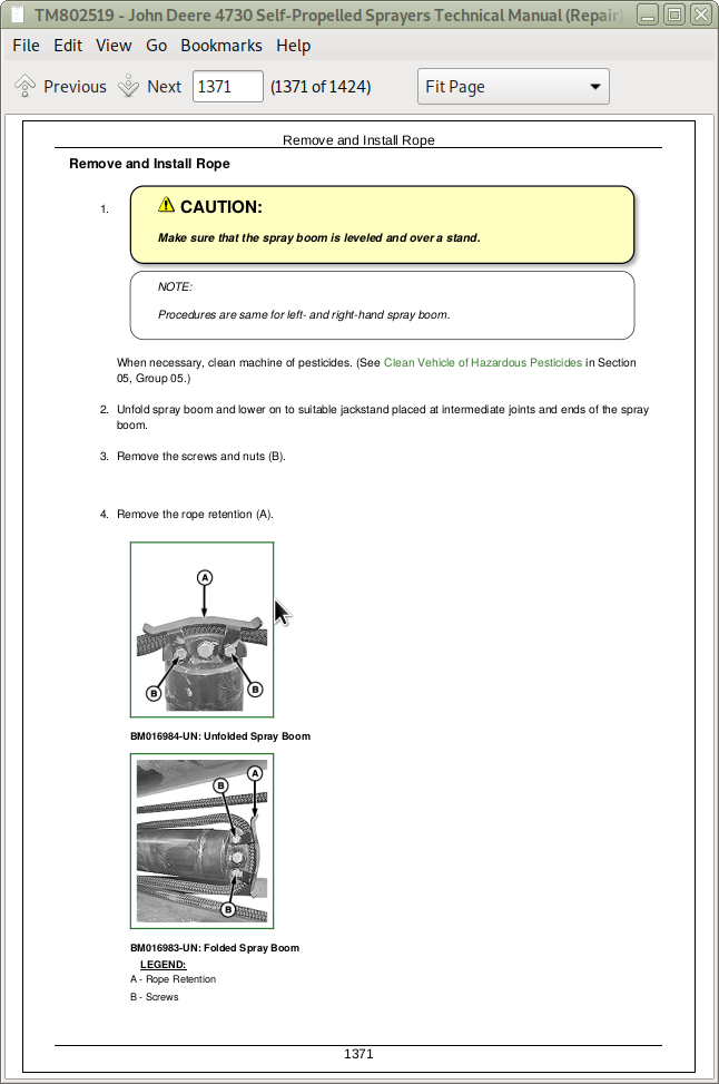
Remove and Install Rope
Spray Boom Carbon Fiber Repair
Remove and Install Spray Boom Inner
Remove and Install Spray Boom Outer
Remove and Install Breakaway
Remove and Install Breakaway Retention Brackets
Check Outer Spray Boom Cylinder Brackets
Adjust Outer Wing Suspension
Check and Adjust Tensioner 3 (T3)
Adjust Breakaway Tension
Adjust Breakaway Alignment
Adjust Outer Fold Cylinder
Remove and Install Greaseless Bushings
Section 199: Dealer Fabricated Tools
Group 05: Dealer Fabricated Tools
DFN20 Solution Pump Seal Driver
DFN21 Pump Support Fixture
DFN22 Bearing Seat Driver
DFN23 Hydrostatic Motor Seal Driver
DFNX65-A1 Eccentric Plug Adjustment Tool
DFNX65-A2 Sizing Arbor
DFNXT1—High Pressure Flange Wrench
DFNXT2—Agitation Nozzle Tool
DFRW151—Radiator Cap Adapter
DFNXT13—Rear Planetary Assembly Spacer
John Deere Self-Propelled Sprayers 4730 (Brazil) Repair Service Manual (TM802519)
![]()