
John Deere Self-Propelled Sprayers 4730 and 4830 Diagnostic and Tests Service Manual (TM2369)
Complete Operation & Test manual with Electrical Wiring Diagrams for John Deere Self-Propelled Sprayers 4730 and 4830, with all the workshop information to maintain, diagnose, and rebuild like professional mechanics.
John Deere Self-Propelled Sprayers 4730 and 4830 workshop Operation & Test manual includes:
* Numbered table of contents easy to use so that you can find the information you need fast.
* Detailed sub-steps expand on repair procedure information
* Numbered instructions guide you through every repair procedure step by step.
* Troubleshooting and electrical service procedures are combined with detailed wiring diagrams for ease of use.
* Notes, cautions and warnings throughout each chapter pinpoint critical information.
* Bold figure number help you quickly match illustrations with instructions.
* Detailed illustrations, drawings and photos guide you through every procedure.
* Enlarged inset helps you identify and examine parts in detail.
TM2369 - John Deere 4730 and 4830 Self-Propelled Sprayers Technical Manual (Operation & Test).PDF
TM2369 - John Deere 4730 and 4830 Self-Propelled Sprayers Technical Manual (Operation & Test).EPUB
Total Pages: 3,351 pages
File Format: PDF/EPUB/MOBI/AZW (PC/Mac/Android/Kindle/iPhone/iPad; bookmarked, ToC, Searchable, Printable)
Language: English
MAIN SECTIONS
Diagnostic Trouble Codes (DTC)
ATC - Automatic Temperature Control DTC
BHC - Boom Hydraulic Controller DTC
CCU - Chassis Control Unit DTC
ECU - Engine Control Unit DTC
iTC - Integrated Terrain Compensation DTC
SRC - Spray Rate Controller DTC
SSU - Steering System Unit DTC
TEC - Tractor Equipment Control DTC
TEI - Tractor Equipment Interface DTC
Observable Symptoms
Engine System
Air Intake and Cooling System
Electrical
Power Train
Brake System
Hydraulic System
Hydraulic Tread Adjust
Steering
Operator Station
Solution System
Foamer System
Auto Suspension Leveling System
Engine System
Air Intake and Cooling Systems
Electrical
General Information - Electrical Section
Component Identification
Accessing Diagnostic Codes and Addresses
Calibration Procedures
Diagnostic Trouble Codes
Diagnostic Addresses
Component Tests - ATC
Component Tests - Other
Agitation
Auxiliary Power
Backup Alarm
Boom Leveling
Boom Unfold and Fold
CAN Bus
Caution Light
Charging System
Controller
Drivetrain Status
Electric Fuel Pump
Engine Air Filter Switch
Engine and Fuel Control
Engine Coolant Sensor
Engine Oil Pressure Switch
Engine Speed Sensor
Foam Marker (Dual Drop)
Foam Marker (Single Drop)
Fuel Level Sensor
Glow Plug
GPS Receiver
GreenStar AUTOTRAC
Horn
Hydraulic Oil Temperature Sensor
Hydrostatic Boost
Ladder
Lighter
Lighting
Load Sense Jam Valve
Operator Presence Switch
Park Brake
Power
Radar Sensor
Radio and Clock
Seat Adjust
Solution Pressure
Solution Pump
Speed Range
Spray Valve Control
Spray Rate
Starting System
Stop Light
Throttle
Traction Control
Tread Adjust
Wheel Speed Sensor
Power Train
Brake Systems
Hydraulic System
Suspension and Tread Adjust
Steering System
Operator Station
Solution System
Foamer
Automatic Air Suspension Leveling System
Service Tools
tm2369 - 4730/4830 Self-Propelled Sprayer Diagnosis and Test
Table of Contents
Foreword
Section 210: General Information
Group 05: Safety
Recognize Safety Information
Understand Signal Words
Perform Service Safely
Wait Before Opening High-Pressure Fuel System
Service Accumulator Systems Safely
Handle Fluids Safely—Avoid Fires
Prevent Battery Explosions
Prepare for Emergencies
Protect Against High Pressure Spray
Prevent Acid Burns
Wear Protective Clothing
Handle Agricultural Chemicals Safely
Service and Operate Chemical Sprayers Safely
Avoid Contact with Agricultural Chemicals
Clean Vehicle of Hazardous Pesticides
Support Machine Properly
Service Machines Safely
Practice Safe Maintenance
Avoid Harmful Asbestos Dust
Work In Ventilated Area
Work in Clean Area
Remove Paint Before Welding or Heating
Avoid Heating Near Pressurized Fluid Lines
Avoid High-Pressure Fluids
Service Tires Safely
Service Cooling System Safely
Illuminate Work Area Safely
Replace Safety Signs
Use Proper Lifting Equipment
Use Proper Tools
Construct Dealer-Made Tools Safely
Decommissioning — Proper Recycling and Disposal of Fluids and Components
Live With Safety
Group 10: Machine Specifications
Machine Specification
Dimensions
Dimensions—All Machines
Metric Bolt and Screw Torque Values
Unified Inch Bolt and Screw Torque Values
High Pressure Face Seal Torque Chart
Service Recommendations For Flat Face O-Ring Seal Fittings
Limited Battery Warranty
Keep Proof of Ownership
Keep Machines Secure
Group 20: Machine Component Location
Identification Numbers
Section 211: Diagnostic Trouble Codes
Group 1: ATC - Automatic Temperature Control Diagnostic Trouble Codes
ATC 000170.03 - Cab Temperature Sensor Circuit Voltage High
ATC 000170.04 - Cab Temperature Sensor Circuit Voltage Low
ATC 000628.12 - ATC Programming
ATC 000630.02 - ATC Calibration Fault - Data Invalid
ATC 000639.14 - ATC CAN Error Limit Exceeded
ATC 000871.03 - Refrigerant Pressure Sensor Circuit Voltage High
ATC 000871.04 - Refrigerant Pressure Sensor Circuit Voltage Low
ATC 000871.13 - Sensor for Refrigerant Pressure, Refrigerant Pressure Out of Valid Range Low
ATC 000876.03 - Compressor Clutch Circuit Voltage High
ATC 000876.04 - Compressor Clutch Circuit Voltage Low
ATC 000876.10 - Excessive A/C Clutch Cycling
ATC 000876.14 - Compressor Shut Off Due to Engine Overheat
ATC 000923.03 - Circulation Blower Motor Circuit Voltage High
ATC 000923.04 - Circulation Blower Motor Circuit Voltage Low
ATC 000923.12 - Circulation Blower Motor Driver Circuit Fault
ATC 001079.03 - ATC Sensor Supply Voltage High
ATC 001079.04 - ATC Sensor Supply Voltage Low
ATC 001546.03 - Water Valve Position Sensor Circuit Voltage High
ATC 001546.04 - Water Valve Position Sensor Circuit Voltage Low
ATC 001547.03 - Evaporator Temperature Sensor Circuit Voltage High
ATC 001547.04 - Evaporator Temperature Sensor Circuit Voltage Low
ATC 001548.03 - Outlet Air Temperature Sensor Circuit Voltage High
ATC 001548.04 - Outlet Air Temperature Sensor Circuit Voltage Low
ATC 001549.03 - Water Valve Motor Circuit Voltage High
ATC 001549.04 - Water Valve Motor Circuit Voltage Low
ATC 001549.07 - Water Valve Motor Mechanical Fault
ATC 001549.13 - Water Valve Motor Not Calibrated
ATC 001551.03 - Pressurizer Blower Motor Circuit Voltage High
ATC 001551.04 - Pressurizer Blower Motor Circuit Voltage Low
ATC 001552.03 - Cab Temperature Control Circuit Voltage High
ATC 001552.04 - Cab Temperature Control Circuit Voltage Low
ATC 001553.03 - Blower Control Circuit Voltage High
ATC 001553.04 - Blower Control Circuit Voltage Low
ATC 002000.09 - ECU Message Missing
ATC 523848.03 - Air Flow Mode Motor Circuit Voltage High
ATC 523848.04 - Air Flow Mode Motor Circuit Voltage Low
ATC 523848.05 - Air Flow Mode Motor Circuit Current Low
ATC 523848.06 - Air Flow Mode Motor Circuit Current High
ATC 523848.07 - Air Flow Mode Motor Mechanical Fault
ATC 523848.13 - Air Flow Mode Motor Not Calibrated
ATC 524202.03 - Ambient Temperature Sensor Circuit Voltage High
ATC 524202.04 - Ambient Temperature Sensor Circuit Voltage Low
ATC 524203.03 - Ambient Temperature Sensor Circuit Voltage High
ATC 524203.04 - Ambient Temperature Sensor Circuit Voltage Low
ATC 524219.02 - Defog Sensor Calibration Fault - Data Invalid
ATC 524219.03 - Defog Sensor Circuit Voltage High
ATC 524219.04 - Defog Sensor Circuit Voltage Low
Group 2: BHC - Boom Hydraulic Controller Diagnostic Trouble Codes
BHC 000158.00 - Switched Supply Voltage High
BHC 000158.01 - Switched Supply Voltage Low
BHC 000237.02 - VIN Security Data Conflict
BHC 000237.14 - VIN Security Not Enabled
BHC 000237.31 - VIN Security Messages Missing
BHC 000628.12 - Programming
BHC 000629.12 - Control Unit Fault
BHC 000630.02 - Calibration Fault/Data Invalid
BHC 000639.14 - CAN Error - Limit Exceeded
BHC 001231.14 - CAN 2 Error Limit Exceeded
BHC 002065.14 - PVT Missing
BHC 002071.09 - ECU Message Missing
BHC 002170.09 - BHC Sensor Missing
BHC 522316.03 - Boom Center Frame Height Sensor Voltage is Above Normal
BHC 522316.04 - Boom Center Frame Height Sensor Voltage is Below Normal
BHC 522316.13 - Boom Center Frame Height Sensor is Out of Calibration
BHC 522372.13 - Right Hand Inner Calibration
BHC 522377.13 - Right Hand Outer Calibration
BHC 522378.13 - Left Hand Inner Calibration
BHC 522380.13 - Left Hand Outer Calibration
BHC 523461.03 - Roll Bias Sensor High
BHC 523461.04 - Roll Bias Sensor Low
BHC 523461.13 - Boom Roll Bias Sensor Out of Calibration
BHC 523463.05 - Roll Bias Left Coil Current Low
BHC 523463.06 - Roll Bias Left Coil Current High
BHC 523464.05 - Roll Bias Right Coil Current Low
BHC 523464.06 - Roll Bias Right Coil Current High
BHC 523477.05 - Center Frame Lower Coil Current is Below Normal or Open Circuit
BHC 523477.06 - Center Frame Lower Coil Current is Above Normal or Short Circuit
BHC 523478.05 - Center Frame Raise Coil Current is Below Normal or Open Circuit
BHC 523478.06 - Center Frame Raise Coil Current is Above Normal or Short Circuit
BHC 523479.05 - Left Boom Tilt Down Coil Current is Below Normal or Open Circuit
BHC 523479.06 - Left Boom Tilt Down Raise Coil Current is Above Normal or Short Circuit
BHC 523480.05 - Right Boom Tilt Down Coil Current is Below Normal or Open Circuit
BHC 523480.06 - Right Boom Tilt Down Raise Coil Current is Above Normal or Short Circuit
BHC 523481.05 - Left Boom Tilt Up Coil Current is Below Normal or Open Circuit
BHC 523481.06 - Left Boom Tilt Up Raise Coil Current is Above Normal or Short Circuit
BHC 523482.05 - Right Boom Tilt Up Coil Current is Below Normal or Open Circuit
BHC 523482.06 - Right Boom Tilt Up Raise Coil Current is Above Normal or Short Circuit
Group 3: CCU - Chassis Control Unit Diagnostic Trouble Codes
CCU 000070.02 - Park Brake Switch Fault
CCU 000096.01 - Fuel Level Low
CCU 000096.05 - Fuel Sensor Circuit Open
CCU 000096.06 - Fuel Sensor Circuit Closed
CCU 000158.00 - CCU-SRC Switched Supply Voltage High
CCU 000158.01 - CCU-SRC Switched Supply Voltage Low
CCU 000237.02 - VIN Data Does Not Match Other Controllers
CCU 000237.14 - VIN Security Not Enabled
CCU 000237.31 - VIN Messages Missing
CCU 000628.12 - CCU Programming
CCU 000629.12 - CCU Control Unit Fault
CCU 000630.02 - CCU Calibration Fault/Data Invalid
CCU 000639.14 - CCU CAN 1 Message Overflow
CCU 001231.14 - CCU CAN 2 Message Overflow
CCU 001504.02 - Operator Seat Switch Fault
CCU 001592.02 - Left Front Wheel Speed Sensor Frequency Invalid
CCU 002000.09 - ECU Message Missing
CCU 002246.09 - Multifunction Control Handle Message Missing
CCU 524279.31 - Operator Out of Seat
Group 4: ECU - Engine Control Unit Diagnostic Trouble Codes
ECU 000091.09 - Throttle Communication Signal Erratic
ECU 000097.03 - Water-in-Fuel Signal Out of Range High
ECU 000097.04 - Water-in-Fuel Signal Out of Range Low
ECU 000097.16 - Water in Fuel Detected
ECU 000100.01 - Engine Oil Pressure Signal Extremely Low
ECU 000100.03 - Engine Oil Pressure Signal Out of Range High
ECU 000100.04 - Engine Oil Pressure Signal Out of Range Low
ECU 000100.18 - Engine Oil Pressure Signal Moderately Low
ECU 000100.31 - Engine Oil Pressure Invalid
ECU 000102.02 - Intake Manifold Pressure Signal Invalid
ECU 000102.03 - Intake Manifold Pressure Signal Out of Range High
ECU 000102.04 - Intake Manifold Pressure Signal Out of Range Low
ECU 000103.00 - Turbo Speed Signal Extremely High
ECU 000103.02 - Turbo Speed Signal Invalid
ECU 000103.05 - Turbo Speed Sensor Circuit has High Resistance
ECU 000103.06 - Turbo Speed Sensor Circuit has Low Resistance
ECU 000103.08 - Turbocharger Speed Signal Invalid
ECU 000103.31 - TurboCharger Speed Signal Missing
ECU 000105.00 - Intake Manifold Air Temperature Signal Extremely High
ECU 000105.03 - Intake Manifold Air Temperature Signal Out of Range High
ECU 000105.04 - Intake Manifold Air Temperature Signal Out of Range Low
ECU 000105.15 - Intake Manifold Air Temperature Signal Slightly High
ECU 000105.16 - Intake Manifold Air Temperature Signal Moderately High
ECU 000107.00 - Air Filter Differential Pressure High
ECU 000108.02 - Barometric Pressure Signal Invalid
ECU 000110.00 - Engine Coolant Temperature Signal Extremely High
ECU 000110.03 - Engine Coolant Temperature Signal Out of Range High
ECU 000110.04 - Engine Coolant Temperature Signal Out of Range Low
ECU 000110.15 - Engine Coolant Temperature Signal Slightly High
ECU 000110.16 - Engine Coolant Temperature Signal Moderately High Diagnostic Procedure
ECU 000110.17 - Engine Coolant Temperature Signal Slightly Low
ECU 000157.03 - Fuel Rail Pressure Signal Out of Range High
ECU 000157.04 - Fuel Rail Pressure Signal Out of Range Low
ECU 000157.10 - Fuel Rail Pressure Rate of Change Abnormal
ECU 000157.17 - Fuel Rail Pressure Not Developed
ECU 000158.17 - ECU Power Down Error
ECU 000174.00 - Fuel Temperature Signal Extremely High
ECU 000174.03 - Fuel Temperature Signal Out of Range High
ECU 000174.04 - Fuel Temperature Signal Out of Range Low
ECU 000174.16 - Fuel Temperature Signal Moderately High
ECU 000189.00 - Engine Speed Derate Condition Exists
ECU 000190.00 - Engine Speed Extremely High
ECU 000412.00 - EGR Temperature Signal Extremely High
ECU 000412.03 - EGR Temperature Signal Out of Range High
ECU 000412.04 - EGR Temperature Signal Out of Range Low
ECU 000412.16 - EGR Temperature Signal Moderately High
ECU 000611.03 - Injector Shorted to Power
ECU 000611.04 - Injector Shorted to Ground
ECU 000627.01 - Injector Pull In Current Too Low or Hold Current Incorrect
ECU 000629.12 - Bad Intelligent Device or Component
ECU 000629.13 - ECU Programming Error
ECU 000636.02 - Pump Position Sensor Signal Invalid
ECU 000636.05 - Pump Position Sensor Circuit Has High Resistance
ECU 000636.06 - Pump Position Sensor Circuit Has Low Resistance
ECU 000636.08 - Pump Position Sensor Signal Missing
ECU 000636.10 - Pump Position Signal Rate of Change Abnormal
ECU 000637.02 - Crank Sensor Signal Invalid
ECU 000637.05 - Crank Sensor Circuit Has High Resistance
ECU 000637.06 - Crank Sensor Circuit Has Low Resistance
ECU 000637.07 - Crank and Pump Position Signals Out of Sync
ECU 000637.08 - Crank Sensor Signal Missing
ECU 000637.10 - Crank Signal Rate of Change Abnormal
ECU 000641.04 - VGT Actuator Supply Voltage Out of Range Low
ECU 000641.12 - VGT Actuator Communication Error
ECU 000641.13 - VGT Actuator Learn Error
ECU 000641.16 - Turbo Actuator Temperature Moderately High
ECU 000651.02 - Injector Number 1 Part Number Data Invalid
ECU 000651.05 - Injector Number 1 Circuit Has High Resistance
ECU 000651.06 - Injector Number 1 Circuit Has Low Resistance
ECU 000651.07 - Injector Number 1 Not Responding
ECU 000651.13 - Injector Number 1 Calibration Fault
ECU 000652.02 - Injector Number 2 Part Number Data Invalid
ECU 000652.05 - Injector Number 2 Circuit Has High Resistance
ECU 000652.06 - Injector Number 2 Circuit Has Low Resistance
ECU 000652.07 - Injector Number 2 Not Responding
ECU 000652.13 - Injector Number 2 Calibration Fault
ECU 000653.02 - Injector Number 3 Part Number Data Invalid
ECU 000653.05 - Injector Number 3 Circuit Has High Resistance
ECU 000653.06 - Injector Number 3 Circuit Has Low Resistance
ECU 000653.07 - Injector Number 3 Not Responding
ECU 000653.13 - Injector Number 3 Calibration Fault
ECU 000654.02 - Injector Number 4 Part Number Data Invalid
ECU 000654.05 - Injector Number 4 Circuit Has High Resistance
ECU 000654.06 - Injector Number 4 Circuit Has Low Resistance
ECU 000654.07 - Injector Number 4 Not Responding
ECU 000654.13 - Injector Number 4 Calibration Fault
ECU 000655.02 - Injector Number 5 Part Number Data Invalid
ECU 000655.05 - Injector Number 5 Circuit Has High Resistance
ECU 000655.06 - Injector Number 5 Circuit Has Low Resistance
ECU 000655.07 - Injector Number 5 Not Responding
ECU 000655.13 - Injector Number 5 Calibration Fault
ECU 000656.02 - Injector Number 6 Part Number Data Invalid
ECU 000656.05 - Injector Number 6 Circuit Has High Resistance
ECU 000656.06 - Injector Number 6 Circuit Has Low Resistance
ECU 000656.07 - Injector Number 6 Not Responding
ECU 000656.13 - Injector Number 6 Calibration Fault
ECU 000676.03 - Glow Plugs Signal Received When Not Expected
ECU 000676.04 - Glow Plugs Signal Not Received When Expected
ECU 001136.00 - ECU Temperature Signal Extremely High
ECU 001136.16 - ECU Temperature Signal Moderately High
ECU 001172.03 - Compressor Inlet Temperature Signal Out of Range High
ECU 001172.04 - Compressor Inlet Temperature Signal Out of Range Low
ECU 001180.00 - Turbine Inlet Temperature Signal Extremely High
ECU 001180.16 - Turbine Inlet Temperature Signal Moderately High
ECU 001209.02 - Exhaust Pressure Incorrect
ECU 001209.03 - Exhaust Pressure Sensor Voltage Out Of Range High
ECU 001209.04 - Exhaust Pressure Sensor Voltage Out Of Range Low
ECU 001347.03 - High Pressure Fuel Pump Control Valve Signal Out of Range High
ECU 001347.05 - High Pressure Fuel Pump Solenoid Number 1 Circuit Has High Resistance
ECU 001347.07 - High Pressure Fuel Pump Not Able to Meet Required Rail Pressure
ECU 001569.31 - Engine in Derate Condition
ECU 002005.19 - Invalid Engine Hour Request
ECU 002630.00 - Charge Air Cooler Outlet Temperature Signal Extremely High
ECU 002630.03 - Charge Air Cooler Outlet Temperature Signal Out of Range High
ECU 002630.04 - Charge Air Cooler Outlet Temperature Signal Out of Range Low
ECU 002630.15 - Charge Air Cooler Outlet Temperature Signal Slightly High
ECU 002630.16 - Charge Air Cooler Outlet Temperature Signal Moderately High
ECU 002659.02 - EGR Mass Flow Rate Data Invalid
ECU 002659.15 - EGR Mass Flow Rate Data Slightly High
ECU 002659.17 - EGR Mass Flow Rate Data Slightly Low
ECU 002790.16 - Calculated Turbine Outlet Temperature Moderately High
ECU 002791.02 - EGR Valve Position Signal Invalid
ECU 002791.03 - EGR Valve Position Signal Out of Range High
ECU 002791.04 - EGR Valve Position Signal Out of Range Low
ECU 002791.07 - EGR Valve Not Reaching Expected Position
ECU 002791.13 - EGR Valve Calibration Change Error
ECU 002791.31 - EGR Valve Calibration Change over a Long Time
ECU 002795.07 - VGT Actuator Not Reaching Expected Position
ECU 003509.03 - Sensor Supply Number 1 Voltage Out of Range High
ECU 003509.04 - Sensor Supply Number 1 Voltage Out of Range Low
ECU 003510.03 - Sensor Supply Number 2 Voltage Out of Range High
ECU 003510.04 - Sensor Supply Number 2 Voltage Out of Range Low
ECU 003511.03 - Sensor Supply Number 3 Voltage Out of Range High
ECU 003511.04 - Sensor Supply Number 3 Voltage Out of Range Low
ECU 003512.03 - Sensor Supply Number 4 Voltage Out of Range High
ECU 003512.04 - Sensor Supply Number 4 Voltage Out of Range Low
ECU 003513.03 - Sensor Supply Number 5 Voltage Out of Range High
ECU 003513.04 - Sensor Supply Number 5 Voltage Out of Range Low
Group 5: iTC - Integrated Terrain Compensation Diagnostic Trouble Codes
iTC 000168.18 - RTK Base Station Low Voltage
iTC 000232.02 - Corrected GPS Position Not Available
iTC 000232.14 - RTK Extend Lost
iTC 000841.31 - Signal Interference From Satellite
iTC 000956.16 - TCM Not Calibrated
iTC 002146.14 - iTC Temperature Sensor Out Of Range
iTC 002854.31 - RTK Rover Radio Link Lost
iTC 003141.31 - GPS Corrections License has Expired
iTC 003144.13 - Receiver not Receiving on Alternate Frequency
iTC 522552.11 - STARFIRE Network Fault
iTC 523274.02 - GPS Position Not Available
iTC 523309.07 - Yaw Sensor Out Of Range
iTC 523309.16 - Yaw Sensor Not Responding
iTC 523310.02 - Memory Fault
iTC 523319.18 - Low Switched Voltage
iTC 523441.31 - No STARFIRE Height Dimension
iTC 523442.31 - No STARFIRE Fore/Aft Set
iTC 523572.31 - Power Shutdown Fault
iTC 523773.03 - Vehicle CAN High Line Voltage High
iTC 523773.04 - Vehicle CAN High Line Voltage Low
iTC 523774.03 - Vehicle CAN Low Line Voltage High
iTC 523774.04 - Vehicle CAN Low Line Voltage Low
iTC 523792.18 - Low Unswitched Voltage
iTC 524209.16 - RTK Rover Too Far From Base Station
iTC 524210.16 - RTK Base Station Not Using Visible Satellites
iTC 524257.14 - RTK Base Station Position Survey In Progress
iTC 524257.16 - RTK Base Station Relocation
Group 6: SRC - Spray Rate Controller Diagnostic Trouble Codes
SRC 000628.12 - SRC Programming
SRC 000629.12 - SRC Control Unit Fault
SRC 000630.02 - SRC Calibration Fault/Data Invalid
SRC 000639.14 - SRC CAN Message Overflow
SRC 003133.00 - Solution Pump Pressure Too High
SRC 003133.01 - Solution Pump Pressure Low
SRC 003133.03 - Solution Pressure Sensor Voltage High
SRC 003133.04 - Solution Pressure Sensor Voltage Low
SRC 523394.02 - Flow Meter Fault
SRC 523440.00 - SRC Unswitched Sensor Voltage High
SRC 523440.01 - SRC Unswitched Voltage Low
Group 7: SSU - Steering System Unit Diagnostic Trouble Codes
SSU 000162.09 - Transmission Messages Missing
SSU 000168.03 - SSU Unswitched Supply Voltage High
SSU 000168.04 - SSU Unswitched Supply Voltage Low
SSU 000237.31 - VIN Security Messages Missing
SSU 000517.09 - GPS Speed Message Fault
SSU 000628.02 - SSU EOL Data Fault
SSU 000628.12 - SSU Programming
SSU 000629.12 - SSU Control Unit Fault
SSU 000630.13 - SSU Calibration Fault/Not Calibrated
SSU 001079.03 - SSU Sensor Supply Voltage High
SSU 001079.04 - SSU Sensor Supply Voltage Low
SSU 001504.07 - Seat Switch Message Fault
SSU 001504.09 - Operator Presence Message Missing
SSU 001504.14 - Operator Not Seated While AutoTrac Active
SSU 001638.09 - Hydraulic Oil Temperature Message Fault
SSU 001807.02 - Steering Wheel Position Sensor 1 Conflict
SSU 001807.03 - Steering Wheel Position Sensor 1 Circuit Voltage High
SSU 001807.04 - Steering Wheel Position Sensor 1 Circuit Voltage Low
SSU 001807.05 - Steering Wheel Position Sensor 1 Circuit Current Low
SSU 001807.06 - Steering Wheel Position Sensor 1 Circuit Current High
SSU 001807.10 - Steering Wheel Position Sensor 1 Signal Mismatch
SSU 001807.14 - Steering Wheel Position Sensor 1 Signal Fault
SSU 522273.00 - SSU Steering Valve Control Circuit Command High
SSU 522273.01 - SSU Steering Valve Control Circuit Command Low
SSU 522387.07 - AutoTrac Wheel Angle Sensor or Steering Valve Fault
SSU 522394.09 - TCM Message Missing
SSU 523651.02 - Control Unit Fault
SSU 523698.09 - AMS Display Message Missing or GREENSTAR Display Message Missing
SSU 523766.02 - AutoTrac Activation Code Invalid
SSU 523767.09 - Resume Switch Message Missing
SSU 523795.02 - AutoTrac Steering Valve Workport Connection Backwards
SSU 523795.12 - AutoTrac Steering Valve Fault
SSU 523795.13 - SSU Calibration Fault/Steering Valve
SSU 523810.01 - SSU Steering Valve Supply Voltage Low
SSU 523821.02 - Vehicle Mismatch
SSU 523823.00 - SSU Vehicle Speed Too High
SSU 523824.03 - Steering Wheel Position Sensor 2 Circuit Voltage High
SSU 523824.04 - Steering Wheel Position Sensor 2 Circuit Voltage Low
SSU 523824.05 - Steering Wheel Position Sensor 2 Circuit Current Low
SSU 523824.06 - Steering Wheel Position Sensor 2 Circuit Current High
SSU 523824.10 - Steering Wheel Position Sensor 2 Signal Mismatch
SSU 523824.14 - Steering Wheel Position Sensor 2 Signal Fault
SSU 523826.00 - Wheel Angle Sensor Voltage High
SSU 523826.01 - Wheel Angle Sensor Voltage Low
SSU 523826.02 - Wheel Angle Sensor Voltage Connection Backwards
SSU 523826.07 - Wheel Angle Sensor Voltage Range Fault
SSU 523826.10 - Wheel Motion Detected With No SID Motion
SSU 523826.14 - Wheel Angle Sensor Low Motion Fault
Group 8: TEC - Tractor Equipment Control Diagnostic Trouble Codes
TEC 000628.12 - TEC Programming
TEC 000629.12 - TEC Control Unit Fault
TEC 000630.02 - TEC Calibration Fault/Data Invalid
TEC 000639.12 - TEC Tractor CAN Message Overflow
TEC 000639.14 - TEC Tractor CAN Error Limit Exceeded
TEC 001231.12 - TEC Implement CAN Message Overflow
TEC 001231.14 - TEC Implement CAN Error Limit Exceeded
TEC 522550.14 - ISO Compliant and Non-ISO Compliant Devices on Implement Bus
Group 9: TEI - Tractor Equipment Interface Diagnostic Trouble Codes
TEI 000628.12 - TEI Programming
TEI 000629.12 - TEI Control Unit Fault
TEI 000630.02 - TEI Calibration Fault/Data Invalid
TEI 522550.14 - ISO Compliant and Non-ISO Compliant Devices on Implement Bus
Group 10: RG3 — Row Guidance Controller
RG3 000158.03 - Key Switch Battery Voltage Above Normal, or Shorted to High Source
RG3 000158.04 - Keyswitch Battery Voltage Below Normal, or Shorted to Low Source
RG3 000168.03 - Power Input Voltage Above Normal, or Shorted to High Source
RG3 000168.04 - Battery Voltage Below Normal, or Shorted to Low Source
RG3 000629.12 - Controller, Bad Intelligent Device, or Component
RG3 000629.14 - Controller, Special Instructions
RG3 516148.02 - Camera System State. Data Erratic, Intermittent or Incorrect
RG3 516148.03 - Camera System State, Voltage Above Normal, or Shorted to High Source
RG3 516148.06 - Camera System State, Current Above Normal or Grounded Circuit
RG3 516148.09 - Camera System State, Abnormal Update Rate
RG3 516148.11 - Camera System State, Root Cause Not Known
RG3 516148.12 - Camera System State, Bad Intelligent Device, or Component
RG3 516148.13 - Camera System State, Out of Calibration
RG3 516148.14 - Camera System State, Special Instructions
RG3 516148.31 - Camera System State, Not Available or Condition Exists
RG3 520870.02 - Non-Volatile Memory Zone 1, Data Erratic, Intermittent or Incorrect
RG3 523674.03 - Row Guidance Sensors, Voltage Above Normal, or Shorted to High Source
RG3 523674.05 - Row Guidance Sensors, Current Below Normal or Open Circuit
RG3 523674.06 - Row Guidance Sensors, Current Above Normal or Grounded Circuit
RG3 523675.03 - Row Guidance Right Sensor, Voltage Above Normal, or Shorted to High Source
RG3 523675.04 - Row Guidance Right Sensor, Voltage Below Normal, or Shorted to Low Source
RG3 523675.18 - Row Guidance Right Sensor, Data Valid but Below Normal Operating Range - Moderately Severe Level
RG3 523676.03 - Row Guidance Left Sensor, Voltage Above Normal, or Shorted to High Source
RG3 523676.04 - Row Guidance Left Sensor, Voltage Below Normal, or Shorted to Low Source
RG3 523676.18 - Row Guidance Left Sensor, Data Valid but Below Normal Operating Range - Moderately Severe Level
Section 212: Observable Symptoms
Group 220: Engine System
Engine System Diagnostics
Group 230: Air Intake and Cooling System
Air Intake and Cooling System Diagnostics
Group 240: Electrical Diagnosis and Tests
Diagnostic Code and Address List
Agitation Diagnostics
Air Quality Diagnostics - Manual Air Conditioning
Air Quality Diagnostics - Automatic Temperature Control
Auxiliary Power Diagnostics
Boom Left Hand Leveling Diagnostics
Boom Raise Lower Diagnostics
Boom Return to Height Diagnostics
Boom Right Hand Leveling Diagnostics
Boom Roll Bias Diagnostics
Boom Fold Unfold Diagnostics
BoomTrac Pro Diagnostics
CAN Bus Diagnostics
CAN Multifunction Control Handle Diagnostics
Caution Light Diagnostics
Charging System Diagnostics
Dome and Sentry Light Diagnostics
Engine Air Filter Switch Diagnostics
Engine Control Unit Diagnostics
Engine and Fuel Control Diagnostics
Engine Coolant Sensor Diagnostics
Engine Oil Pressure Switch Diagnostics
Engine Speed Sensor Diagnostics
Foam Marker Diagnostics, Dual Drop
Foam Marker Diagnostics, Single Drop
Fuel Level Sensor Diagnostics
Glow Plug Diagnostics
GPS Receiver Diagnostics (Non-Deere)
Greenstar AutoTrac Diagnostics
Greenstar Display Diagnostics
Greenstar External Display Control Diagnotics
Greenstar Field Doc Diagnostics
GREENSTAR GREENSTAR is a trademark of Deere & Company Data Card Diagnostics
Greenstar Parallel Tracking Diagnostics
Greenstar RTK Type Identification
Greenstar RTK With Starfire ITC Diagnostic A
Greenstar RTK With Starfire Diagnostics
Starfire Type Identification
Starfire ITC Diagnostics Type A
Starfire With TCM Diagnostics
Horn Diagnostics
Hydraulic Oil Temperature Sensor Diagnostics
Hydrostatic Boost Diagnostics
Ladder Diagnostics
Lighter Diagnostics
Lighting Diagnostics
Load Sense Jam Valve Diagnostics
Operator Presence Switch Diagnostics
Park Brake Diagnostics
Power Diagnostics
Radar Sensor Diagnostics
Radio and Clock Diagnostics
Seat Adjust Diagnostics
Solution Pressure Diagnostics
Solution Pump Diagnostics
Speed Range Diagnostics
Spray Nozzle Control Diagnostics
Spray Rate Diagnostics
Starting System Diagnostics
Stop Light Diagnostics
Swath Control Pro Diagnostics
Throttle Diagnostics
Traction Control Diagnostics
Tread Adjust Diagnostics
Wheel Speed Sensor Diagnostics
Wiper Diagnostics
Group 250: Power Train Diagnosis and Tests
Final Drive Diagnostics
Hydrostatic Drive Diagnostics
Hydrostatic Reverse Boost Diagnostics
Traction Control Diagnostics
Group 260: Brake System Diagnosis and Tests
Park Brake Diagnostics
Service Brake Diagnostics
Group 270: Hydraulic System Diagnosis and Tests
Basic Hydraulic System Diagnostics
Boom, Left Hand Leveling Diagnostics
Boom Raise/Lower Diagnostics
Boom, Right Hand Leveling Diagnostics
Boom Roll Bias Diagnostics
Boom Fold/Unfold Diagnostics, Boom
Power Washer Diagnostics
Solution Pump Diagnostics
Group 275: Hydraulic Tread Adjust Diagnostics
Suspension and Hydraulic Tread Adjust Diagnostics
Group 280: Steering Diagnostics
Steering System Tests and Adjustments
Group 290: Operator Station Diagnostics
Manual Air Conditioning and Heater Diagnostics
ATC Air Conditioning and Heater Diagnostics
Group 300: Solution System Diagnostics
Eductor Diagnostics
Erratic Rate Diagnostics
Solution Loading Diagnostics
Solution System Pressure Diagnostics
Over or Under Application Diagnostics
Group 310: Foamer System Diagnostics
Foamer System Diagnostics
Group 320: Auto Suspension Leveling System Diagnostics
Auto Suspension Leveling System Diagnostics
Section 220: Engine System
Group 05: General Information
General Information — Engine
Engine Component Glossary
Engine Diagnostic Specifications
Group 10: Test Procedures and Adjustments
Air in Return Fuel Test
Engine Oil Pressure Test
Turbocharger Boost Test
Bleeding Fuel Systems
Fuel Transfer Pump Pressure Test - 6068 Engine
Group 15: Engine Diagnostics
Engine Diagnostics
Section 230: Air Intake and Cooling Systems
Group 05: General Information
General Information — Air Intake and Cooling Systems
Service Cooling System Safely
Decommissioning — Proper Recycling and Disposal of Fluids and Components
Group 10: Test Procedures and Adjustments
Testing Aftercooler For Leaks
Turbocharger Boost Test
Test Radiator Cap
Test Cooling System
Inspect Thermostat and Test Opening Temperature
Radiator Inspection
Group 15A: Air Intake System Diagnostics
Engine Diagnostics
Group 15B: Engine Cooling Package Diagnostics
Theory of Operation
Engine Cooling Package Diagnostics
Section 240: Electrical Diagnosis and Tests
Group 05A: General Information - Electrical Section
How to Use the Electrical Diagnostic Section
Intermittent Fault Diagnostics
Programming Control Units
Group 05B: Component Identification
Electrical Component Identification Legend
Load Center Fuses
Load Center Relays and Diodes
Group 10A: Accessing Diagnostic Codes and Addresses
Accessing GREENSTAR 2 Diagnostic Trouble Codes
Accessing GREENSTAR 2 Diagnostic Addresses
GREENSTAR 2 Screen Capture
Group 10B: Calibration Procedures
Automatic Temperature Control Unit (ATC) Calibration
Calibrate Pressure Sensor
Calibrating Solution Pump
Calibrate Boom Return To Height
Calibrate Boom Heights Sensors
Calibrate Boom Level Position
Calibrating Wheel Speed Sensor
Calibrating Radar Sensor (Optional)
Calibration Procedure - Steering System EH Valve
Greenstar AutoTrac SSU Address Adjustments
Group 10C: Caution and Warning Messages
Caution and Warning Messages Information
Control Unit Info
SPRAYSTAR Caution and Warning Statements
Message Center Cautions and Warnings
Warning
Chassis Caution Alarms
Solution System Caution Alarms
Engine Caution Alarms
Chassis Warning Alarms
Solution System Warning Alarms
Engine Warning Alarms
Group 10D: Diagnostic Trouble Codes
ACU Diagnostic Trouble Codes
ATC Diagnostic Trouble Codes
BHC Diagnostic Trouble Codes
CCU Diagnostic Trouble Codes
ECU Diagnostic Trouble Codes
iTC Diagnostic Trouble Codes
SRC Diagnostic Trouble Codes
SSU Diagnostic Trouble Codes
TEC and TEI Diagnostic Trouble Codes
UIM Diagnostic Trouble Codes
VTi Diagnostic Trouble Codes
Group 10E: Diagnostic Addresses
ATC Controller Addresses
BHC Controller Addresses
CCU Controller Addresses
ECU Controller Addresses
JDL Addresses
SRC Controller Addresses
SSU Controller Addresses
VTi Controller Addresses
Group 10F: Component Tests — ATC
ATC - Automatic Temperature Control Unit System Power and Ground Circuit Test
ATC - Air Flow Mode Motor Circuit Test
ATC - Ambient Temperature Sensor Circuit Test
ATC - Beep Mode Test
ATC - Blower Motor Driver Circuit Test
ATC - Cab Temperature Sensor Circuit Test
ATC - Circulation Blower Motor Circuit Test
ATC - Evaporator Temperature Sensor Circuit Test
ATC - Outlet Air Temperature Sensor Circuit Test
ATC - Pressurizer Blower Motor Circuit Test
ATC - Refrigerant Pressure Sensor Circuit Test
ATC - Water Valve Motor Circuit Test
Group 10G: Component Tests — Other
Boom Shutoff Valve Mechanical Check
Greenstar AutoTrac Diagnostic Address Tests
Greenstar AutoTrac EH Valve Test
Group 15A: Agitation Diagnostics
Theory of Operation
Agitation Schematic
Agitation Diagnostics
Group 15B: Air Quality Diagnostics - Manual Air Conditioning
Theory of Operation
Air Quality Schematic - Manual Air Conditioning
Air Quality Diagnostics - Manual Air Conditioning
Group 15C: Air Quality Diagnostics - Automatic Temperature Control
Air Quality Schematic - Automatic Temperature Control
Automatic Temperature Control (ATC) Diagnostics
Group 15D: Auxiliary Power Diagnostics
Theory of Operation
Auxiliary Power Schematic
Auxiliary Power Diagnostics
Group 15E: Backup Alarm
Backup Alarm Schematic
Group 15F: Boom Leveling Diagnostics - Left Hand
Boom Leveling Theory of Operation
Boom Electrical Schematic
Left Boom Leveling Diagnostics
Group 15G: Boom Leveling Diagnostics - Right Hand
Boom Leveling Theory of Operation
Boom Electrical Schematic
Right Boom Leveling Diagnostics
Group 15H: Boom Raise/Lower Diagnostics
Theory of Operation
Boom Electrical Schematic
Boom Raise/Lower Diagnostics
Group 15I: Boom Return to Height Diagnostics
Theory of Operation
Boom Electrical Schematic
Boom Return to Height Diagnostics
Group 15J: Boom Roll/Bias Diagnostics
Theory of Operation
Boom Electrical Schematic
Boom Roll Bias Diagnostics
Group 15K: BoomTrac Pro Boom Leveling System Diagnostics
BoomTrac Pro Theory of Operation
Auto Boom Leveling Electrical Schematic
BoomTrac Pro Leveling System Electrical Diagnostics
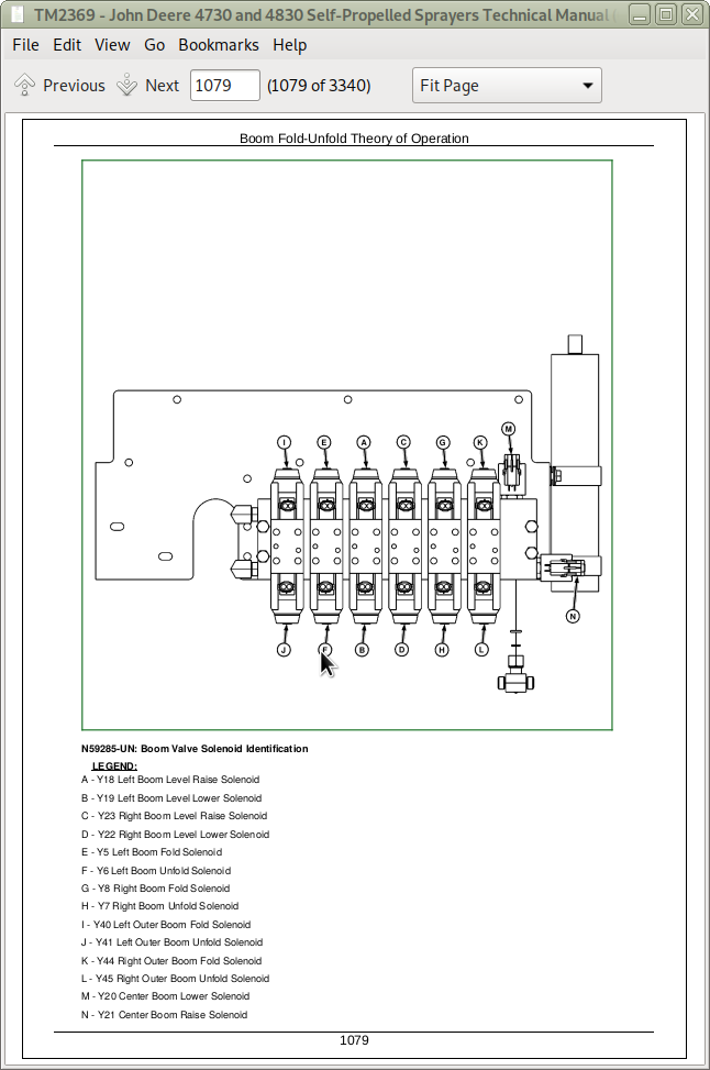
Group 15L: Boom Unfold and Fold Diagnostics
Boom Fold-Unfold Theory of Operation
Boom Electrical Schematic
Overall Boom Unfold and Fold Diagnostics
Left Boom Unfold and Fold Diagnostics
Right Boom Unfold and Fold Diagnostics
Group 15M: CAN Bus Diagnostics
CAN Bus Theory of Operation
CAN Bus Schematic
CAN Bus 1 Diagnostics
CAN Bus 2 Diagnostics
CAN Bus 3 Diagnostics
Group 15N: CAN Multifunction Control Handle Diagnostics
Multifunction Control Handle Theory of Operation
CAN Bus Schematic
CAN Multifunction Control Handle Diagnostics
Group 15O: Caution Light Diagnostics
Theory of Operation
Caution and Stop Light Schematic
Caution Light Diagnostics
Group 15P: Charging System Diagnostics
Charging System Theory of Operation
Charging System Schematic
Battery Tests
Charging System Diagnostics
Group 15Q: Controller Diagnostics - ATC (Automatic Temperature Controller)
Theory of Operation
Air Quality Schematic - Automatic Temperature Control
CAN Bus Schematic
ATC Diagnostics
Group 15R: Controller Diagnostics - BHC (Boom Hydraulics Controller)
Boom Hydraulics Controller (BHC) Theory of Operation
Boom Hydraulics Controller (BHC) Schematic
Boom Hydraulics Controller (BHC) Diagnostics
Group 15S: Controller Diagnostics - CCU-SRC (Chassis Control Unit-Spray Rate Controller)
Theory of Operation
Spray Rate Controller Schematic
CCU-SRC Power Diagnostics
Group 15T: Controller Diagnostics - ECU (Engine Control Unit)
Theory of Operation
Engine Control Unit Schematic
Engine Sensor Schematic
CAN Bus Schematic
Engine Control Unit - Overall Diagnostics
Group 15U: Controller Diagnostics - SSU (Steering System Unit)
Theory of Operation
Steering System Unit Power Schematic
Group 15V: Dome and Entry Light Diagnostics
Theory of Operation
Dome and Entry Lamp Schematic
Dome and Entry Light Diagnostics
Group 15W: Drivetrain Status
Drivetrain Status Theory of Operation
Drivetrain Status Schematic
Group 15X: Electric Fuel Pump
Engine Fuel System Theory of Operation
Electric Fuel Pump Schematic
Electric Fuel Pump Diagnostics
Group 15Y: Engine Air Filter Switch Diagnostics
Theory of Operation
Engine Sensor Schematic
Engine Air Filter Switch Diagnostics
Group 15Z: Engine and Fuel Control Diagnostics
Theory of Operation
Engine Control Unit Schematic
Engine Sensor Schematic
CAN Bus Schematic
Engine and Fuel Control Diagnostics
Group 15AA: Engine Coolant Sensor Diagnostics
Theory of Operation
Engine Sensor Schematic
Engine Coolant Sensor Diagnostics
Group 15AB: Engine Oil Pressure Switch Diagnostics
Theory of Operation
Engine Sensor Schematic
Engine Oil Pressure Switch Diagnostics
Group 15AC: Engine Speed Sensor Diagnostics
Theory of Operation
Engine Sensor Schematic
Engine Speed Sensor Diagnostics
Group 15AD: Foam Marker (Dual Drop) Diagnostics
Foam Marker (Dual Drop) Electrical Theory of Operation
Foam Marker (Dual Drop) Schematics
Foam Marker (Dual Drop) Diagnostics (S.N. —013000)
Group 15AE: Foam Marker (Single Drop) Diagnostics
Foam Marker (Single Drop) Electrical Theory of Operation
Foam Marker (Single Drop) Schematics
Foam Marker (Single Drop) Diagnostic Procedures (S.N. —013000)
Group 15AF: Fuel Level Sensor Diagnostics
Theory of Operation
Fuel Level Sensor Schematic
Fuel Level Sensor Diagnostics
Group 15AG: Glow Plug Diagnostics
Theory of Operation
Glow Plug Schematic
Engine Sensor Schematic
Glow Plug Diagnostics
Group 15AH: GPS Receiver Diagnostics (Non - Deere)
Theory of Operation
Electrical Schematic
GPS Receiver (Non-Deere) Diagnostics
Group 15AI: GreenStar AUTOTRAC Diagnostics
AutoTrac Theory of Operation
AutoTrac Schematics
AutoTrac Diagnostics
Group 15AJ: GreenStar Display 2600 Diagnostics
Theory of Operation
Greenstar Display GS2 Schematic
GREENSTAR Display Diagnostics - Type A
Group 15AK: GreenStar External Display Control Diagnostics
Theory of Operation
Greenstar Display GS2 Schematic
External Display Control Diagnostics
Group 15AL: GreenStar Documentation Diagnostics
Documentation Identification
Theory of Operation
Greenstar Display GS2 Schematic
CAN Bus Schematic
Documentation Diagnostics
Group 15AM: GreenStar Data Card Diagnostics
Theory of Operation
Schematic
Data Card Diagnostics.
Group 15AN: GreenStar Parallel Tracking
Parallel Tracking Theory of Operation
CAN Bus Schematic
Parallel Tracking Diagnostics
Group 15AO: GreenStar RTK (Real Time Kinematic) Type Identification
RTK (Real Time Kinematic) Type Identification
Group 15AP: GreenStar RTK with STARFIRE iTC Diagnostics - Type A
Theory of Operation
Electrical Schematic
Diagnostics
Group 15AQ: GreenStar RTK with STARFIRE (Original) Diagnostics - Type B
Theory of Operation
Electrical Schematic
RTK Diagnostics
Group 15AR: GreenStar STARFIRESTARFIRE is a trademark of Deere & Company Receiver Identification
Type Identification
Group 15AS: GreenStar STARFIRESTARFIRE is a trademark of Deere & Company iTC Diagnostics - Type A
Theory of Operation
Electrical Schematic
STARFIRE STARFIRE is a trademark of Deere & Company iTC Diagnostics
Group 15AT: GreenStar STARFIRESTARFIRE is a trademark of Deere & Company (Original) with TCM Diagnostics - Type C
Theory of Operation
Electrical Schematic
STARFIRE Receiver Diagnostics
Group 15AU: Horn Diagnostics
Theory of Operation
Horn Circuit Schematic
Horn Diagnostics
Group 15AV: Hydraulic Oil Temperature Sensor Diagnostics
Theory of Operation
Hydraulic Oil Temperature Schematic
Hydraulic Oil Temperature Sensor Diagnostics
Group 15AW: Hydrostatic Boost Diagnostics
Theory of Operation
Hydrostatic Boost Schematics
Hydrostatic Boost Diagnostics
Group 15AX: Ladder
Ladder Theory of Operation
Ladder Electrical Schematic
Ladder Diagnostics
Group 15AY: Lighter Diagnostics
Theory of Operation
Lighter Circuit Schematic
Lighter Diagnostics
Group 15AZ: Lighting (Standard Bulbs) Diagnostics
Theory of Operation
Lighting Circuit Operation (Standard Bulbs)
V1 - Diode Block
Warning and Turn Signal Lights Schematic
Warning and Turn Signal Lights Schematic
Road Lights Schematic - Standard Bulbs
Field 1 and Field 2 Lights Schematic - Standard Bulbs
Group 15BA: Lighting (High Intensity Discharge Bulbs) Diagnostics
Theory of Operation
Lighting Circuit Operation (HID Bulbs)
V1 - Diode Block
Warning and Turn Signal Lights Schematic
Road Lights Schematic - High Intensity Discharge Bulbs
Field 1 and Field 2 Lights Schematic - High Intensity Discharge Bulbs
Group 15BB: Load Sense Jam Valve Diagnostics
Theory of Operation
Load Sense Jam Valve Schematics
Load Sense Jam Valve Diagnostics
Group 15BC: Operator Presence Switch Diagnostics
Theory of Operation
Operator Presence Schematic
Operator Presence Switch Diagnostics
Group 15BD: Park Brake Diagnostics
Theory of Operation
Park Brake Electrical Schematic
Park Brake Diagnostics
Group 15BE: Power Diagnostics
Theory of Operation
V1- Diode Block
Power System Schematic
Remote Power Terminals Schematic
Group 15BF: Radar Sensor Diagnostics
Theory of Operation
Radar Sensor Schematic
Radar Sensor Diagnostics
Group 15BG: Radio and Clock Diagnostics
Theory of Operation
Radio and Clock Schematic
Radio and Clock Diagnostics
Group 15BH: Seat Adjust Diagnostics
Theory of Operation
Seat Adjust Schematic
Seat Adjust Diagnostics
Group 15BI: Solution Pressure Diagnostics
Theory of Operation
Solution Pressure Schematic
Solution Pressure Electrical Diagnostics
Group 15BJ: Solution Pump Diagnostics
Theory of Operation
Spray Rate Schematic
Solution Pump Electrical Diagnostics
Group 15BK: Speed Range Diagnostics
Theory of Operation
Speed Range Schematic
Speed Range Diagnostics
Group 15BL: Spray Valve Control Diagnostics
Theory of Operation
Spray Control Schematic
Spray Valve Control Overall Diagnostics
Spray Valve Control (Fence) Diagnostics
Spray Valve Control (Right) Diagnostics
Spray Valve Control (Center) Diagnostics
Spray Valve Control (Left) Diagnostics
Group 15BM: Spray Rate Diagnostics
Theory of Operation
Spray Rate Schematic
Spray Rate Diagnostics
Group 15BN: Starting System Diagnostics
Starting System Theory of Operation
Starting System Schematic
Starting System Diagnostics
Group 15BO: Stop Light Diagnostics
Theory of Operation
Caution and Stop Light Schematic
Stop Light Diagnostics
Group 15BP: Throttle Diagnostics
Theory of Operation
Throttle Schematic
Throttle Diagnostics
Group 15BQ: Traction Control Diagnostics
Theory of Operation
Traction Control Schematic
Traction Control Electrical Diagnostics
Group 15BR: Tread Adjust Diagnostics
Theory of Operation
Tread Adjust Electrical Schematic
Tread Adjust Diagnostics
Group 15BS: Wheel Speed Sensor Diagnostics
Theory of Operation
Wheel Speed Sensor Schematic
Wheel Speed Sensor Diagnostics
Group 15BT: Wiper Diagnostics
Theory of Operation
Wiper Schematic
Wiper Diagnostics
Group 20: Connector Information (end views, numbers, location photos)
Connector Number Designations
X100 - X199 Connectors
X200 - X299 Connectors
X400 - X499 Connectors
X500 - X599 Connectors
X600 - X699 Connectors
X700 - X799 Connectors
Section 250: Power Train Diagnosis and Tests
Group 05: General Information
Power Train General Information
Power Train Component Identification
Power Train Specifications
Power Train Operational Checkout
Group 10: Test Procedures and Adjustments
Adjust Hydrostatic Pump Linkage (12000 —)
Hydrostatic Pump Synchronization Procedure (S.N. -002000)
Pressure Difference Between Hydrostatic Pumps Test
Check Hydrostatic Charge Pressure
Adjust Hydrostatic Charge Pressure with Traction Control Valve
Hydrostatic Pumps Servo Piston Pressure Test
Test and Adjust Hydrostatic Pumps High Pressure Limiter with Traction Control Valve
Test Reverse Boost Engage Pressure
Test Case Drain Flow of Motors For Front Hydrostatic Pump
Test Case Drain Flow of Motors For Rear Hydrostatic Pump
Test Results Worksheet
Group 15A: Final Drive Diagnostics
Theory of Operation
Final Drive Schematic
Final Drive Diagnostics
Group 15B: Hydrostatic Drive Diagnostics
Theory of Operation
Hydrostatic Drive Schematic
Hydrostatic Drive Diagnostics
Group 15C: Hydrostatic Reverse Boost Diagnostics
Theory of Operation
Hydrostatic Reverse Boost Hydraulic Schematic
Reverse Boost Hydraulic Diagnostics
Group 15D: Traction Control Diagnostics
Theory of Operation, Traction Control
Schematic, Traction Control Hydraulics
Traction Control Diagnostics (Pump Isolation)
Group 20: Power Train Component Location
Component Identification
Section 260: Brake Systems Diagnosis and Tests
Group 05: General Information
General Information
Group 10: Test Procedures and Adjustments
Service Brake Pressure Test
Bleeding Service Brakes
Park Brake Release Pressure Test
Park Brake Wheel Hub Release Test
Group 15A: Park Brake Diagnostics
Theory of Operation
Park Brake Schematic
Park Brake Diagnostics
Group 15B: Service Brakes Diagnostics
Theory of Operation
Service Brake Schematic
Service Brake Diagnostics
Section 270: Hydraulic System Diagnosis and Tests
Group 05: General Information
General Information
Hydraulic System Component Glossary
Hydraulic Operational Checks
Group 10: Test Procedures and Adjustments
Test and Adjust Standby Pressure
Test and Adjust Compensator Pressure
Steering Valve Load Sense Relief Test
Test Proportional Valve and Solution Pump Hydraulic Flow Rate
Test Hydraulic Load Sense System
Group 15A: Basic Hydraulic System Diagnostics
Theory of Operation
Hydraulic System Schematic
Hydraulic System Basic Diagnostics
Group 15B: Boom - Left-Hand Leveling Diagnostics
Theory of Operation
Hydraulic System Schematic — Boom
Boom - Left-Hand Leveling Diagnostics
Group 15C: Boom Raise and Lower Diagnostics
Theory of Operation
Hydraulic System Schematic — Boom
Boom Raise and Lower Diagnostics
Group 15D: Boom - Right-Hand Leveling Diagnostics
Theory of Operation
Hydraulic System Schematic — Boom
Boom - Right-Hand Leveling Diagnostics
Group 15E: Boom Roll Bias Diagnostics
Theory of Operation
Hydraulic System - Boom Schematic
Roll Bias Diagnostics
Group 15G: Boom Unfold/Fold Diagnostics
Theory of Operation
Hydraulic System Schematic — Boom
Boom Unfold/Fold Diagnostics
Group 15H: Ladder Diagnostics
Ladder Theory of Operation
Ladder Hydraulic Schematic
Ladder Hydraulic Diagnostics
Group 15I: Power Washer Diagnostics
Theory of Operation
Hydraulic Schematic
Power Washer Diagnostics
Group 15J: Solution Pump Diagnostics
Theory of Operation
Hydraulic System Schematic — Boom
Solution Pump Hydraulic Diagnostics
Group 20: Component Location
Component Identification
Combination Valve Port Locations
Section 275: Suspension and Tread Adjust Diagnosis and Tests
Group 05: General Information
General Information
Tread Adjust Operation Checks
Group 10: Test Procedures and Adjustments
Test and Adjust Compensator Pressure
Tread Adjust Cylinder Leakage Test
Tread Adjust Shim Gap Tests and Adjustments
Suspension Scissors Assembly Adjustment Procedure
Group 15: Tread Adjust Diagnostics
Theory of Operation
Tread Adjust Hydraulic Schematic
Tread Adjust Diagnostics
Group 20: Component Location
Tread Adjust Component Location
Section 280: Steering System Diagnosis and Tests
Group 05: General Information
General Information
Group 10: Test Procedures and Adjustments
Steering Valve Load Sense Relief Test
Toe Control Valve Relief Test
Steering Cylinder Leak Test
Group 15: Steering Diagnostics
Steering Theory of Operation
Steering System Hydraulic Schematics
Steering System Diagnostics
Group 20: Component Location
Component Location
Section 290: Operator Station Diagnosis and Tests
Group 05: General Information
General Information
Air Conditioning System Specifications
Group 10: Test Procedures and Adjustments
A/C - Preliminary Checks
A/C - Temperature Drop Test
Air Conditioner Service Ports
A/C - System Static Pressure Test
A/C - System Pressure Test
Pressure and Leak Testing The Air Conditioning System
Group 15: Air Conditioning and Heating Diagnostics
Theory of Operation
Air Conditioning Schematic
A/C - ATC Operational Check
A/C - Manual Control Operational Check
Air Conditioning Diagnostics
Group 20: Component Location
Air Conditioning System Components
Section 300: Solution System Diagnosis and Tests
Group 05: General Information
General Information
Group 10: Test Procedures and Adjustments
Chemicals, avoid contact
Solution System Checks
Checking Dead Head Pressure
Check Flowmeter Calibration
Solution Pressure Transducer Electrical Test
Boom Shutoff Valve Mechanical Check
Group 15A: Eductor Diagnostics
Solution System Theory of Operation
Solution System Schematic
Solution System Eductor Diagnostics
Group 15B: Erratic Rate Diagnostics
Solution System Theory of Operation
Solution System Schematic
Solution System Erratic Rate Diagnostics
Group 15C: Loading Diagnostics
Solution System Theory of Operation
Solution System Schematic
Solution System Loading Diagnostics
Group 15D: Solution Pressure Diagnostics
Solution System Theory of Operation
Solution System Schematic
Solution System Pressure Diagnostics
Group 15E: Over or Under Application Diagnostics
Solution System Theory of Operation
Solution System Schematic
Solution System Over or Under Application Diagnostics
Group : Component Location
Solution System Component Location
Section 310: Foamer Diagnosis and Tests
Group 05: General Information
Foam Marker General Information
Foam Marker System Operational Checks (On Board Air Supply) (S.N. —013000)
Group 10: Test Procedures and Adjustments
Foam Marker Test Procedures and Adjustments (S.N. —013000)
Group 15A: Foam Marker Diagnostics (S.N. —013000)
Foam Marker Theory of Operation (S.N. —013000)
Foam Marker Schematics (S.N. —013000)
Foamer Diagnostic Procedure (S.N. —013000)
Group 15B: Foam Marker Diagnostics (S.N. 013001— )
Foam Marker Theory of Operation (S.N. 013001— )
Foam Marker Schematics (S.N. 013001— )
Foam Marker Diagnostic Procedure (S.N. 013001— )
Group 20: Component Location
Foamer Component Location
Section 320: Automatic Air Suspension Leveling System Diagnostics and Tests
Group 15: Automatic Air Suspension Leveling System Diagnostics
Theory of Operation
Schematic
Diagnostics
Section 325: AutoTrac RowSense and AutoTrac Vision
Group 20: Theory of Operation
AutoTrac RowSense Harness Routing Overview
AutoTrac RowSense Theory of Operation
AutoTrac Vision Theory of Operation
Row Guidance Control Unit (RG3) — Electrical — Theory of Operation
Group 30: Schematic
AutoTrac RowSense Schematic
AutoTrac Vision Schematic
Controller Area Network (CAN) Bus Path
Control Unit — Row Guidance Control Unit (RG3) — Electrical — Schematic
Group 50: Diagnostic
AutoTrac RowSense Sensor Diagnostic
AutoTrac RowSense Performance Diagnostic
AutoTrac Vision Diagnostic
Section 329: AutoTrac RowSense and Vision - Electrical Component Information
Group 40A: Electrical Assemblies
XA205 — Camera
XA208-1 — Row Guidance Control Unit (RG3)
XA208-2 — Row Guidance Control Unit (RG3)
Group 40B: Sensors
XB201 — RowSense Feeler Sensor, Right Hand
XB202 — RowSense Feeler Sensor, Left Hand
Group 40C: Fuses
XF458 — Fuse
XF459 — Fuse
Group 40D: Interconnects and Ground Points
XX682 — RowSense Harness to Feeler Extension Harness, Right Hand
XX683 — RowSense Harness to Feeler Extension Harness, Left Hand
XX684 — Feeler Extension Harness to Feeler Harness, Right Hand
XX685 — Feeler Extension Harness to Feeler Harness, Left Hand
Section 399: Service Tools
Group 05: Dealer Fabricated Tools
DFN20 Solution Pump Seal Driver
DFN21 Pump Support Fixture
DFN22 Bearing Seat Driver
DFN23 Hydrostatic Motor Seal Driver
DFNX65-A1 Eccentric Plug Adjustment Tool
DFRW130—Relay Circuit Test Lead
DFRW167 — Water Valve Test Harness
Group 10: Service Tools and Kits
38H1029 — Tee (-4 ORFS)
38H1030 — Tee (-6 ORFS)
38H1146 — -6 ORFS Plug
38H1172 — Adapter ( -6 to -10 ORFS)
38H1415 — -6 ORFS Cap
JDG10393 Support Stand
JDG10949 — Sprayer Jack
JT02046 — Charging Station
JT02050 — Recovery and Recycling Station
JT02156A — Digital Pressure and Temperature Analyzer
JT02158 — Digital Pressure and Temperature Analyzer
JT02159 — 20 ft Cable
JT02160 — 10,000 PSI Transducer
JT02161 — 500 PSI Transducer
JT02162 — 5000 PSI Transducer
JT05495 — Adapter Fitting
JT05685 — Battery Load Tester
JT05832 — Battery Load Tester
JT05845 — 2-Speed Hand Pump
JT07253 — Infrared Temperature Gun
MT1531 — Diagnostic Receptacle
XPD341 — Diagnostic Receptacle
XPD34BTX — Diagnostic Receptacle
XPD36BTL — Diagnostic Receptacle
John Deere Self-Propelled Sprayers 4730 and 4830 Diagnostic and Tests Service Manual (TM2369)
![]()