
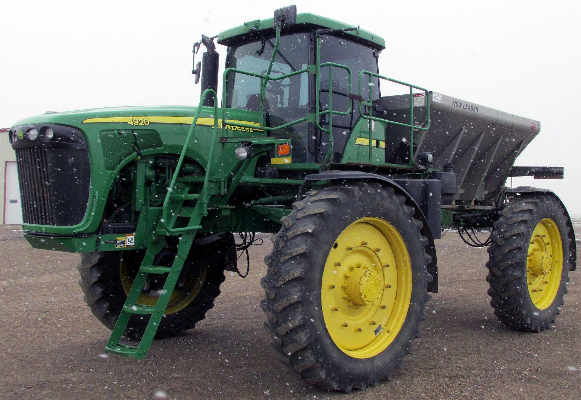
John Deere Self-Propelled Sprayers 4920 Repair Service Manual (TM2124)

Complete service repair manual for John Deere Self-Propelled Sprayers 4920, with all the shop information to maintain, diagnose, and service like professional mechanics.
John Deere Self-Propelled Sprayers 4920 workshop service repair manual includes:
* Numbered table of contents easy to use so that you can find the information you need fast.
* Detailed sub-steps expand on repair procedure information
* Numbered instructions guide you through every repair procedure step by step.
* Notes, cautions and warnings throughout each chapter pinpoint critical information.
* Bold figure number help you quickly match illustrations with instructions.
* Detailed illustrations, drawings and photos guide you through every procedure.
* Enlarged inset helps you identify and examine parts in detail.
TM2124 - John Deere 4920 Self-Propelled Sprayers Technical Manual (Repair).PDF
TM2124 - John Deere 4920 Self-Propelled Sprayers Technical Manual (Repair).epub
Total Pages: 1,112 pages
File Format: PDF/EPUB/MOBI/AZW (PC/Mac/Android/Kindle/iPhone/iPad; bookmarked, ToC, Searchable, Printable)
Language: English
MAIN SECTIONS
Foreword
General Information
Safety
General Information
Fuel and Lubricants
Engine
Component Removal and Installation
Fuel, Air Intake, and Cooling Systems
Diesel Fuel System
Engine Cooling System
Coolers and Air Conditioning Condenser
Electrical
Batteries
Connector Repair
Charging Circuit
Starting Circuit
Fuses and Relays
Spray Rate Control System
Chassis Control System
Engine Control System
Lighting
Cab Components
Wiring Harness Routing
Boom Trac Pro™ System
Power Train Repair
Remove and Install Hydrostatic Components
Hydrostatic Drive Repair
Planetary Hub Repair
Steering and Brakes
Steering Column
Steering Valve
Steering Cylinder
Brakes
AutoTrac Steering System
Suspension and Tread Adjust Repair
Suspension
Tread Adjust Valves
Tread Adjust Cylinders
Tread Adjust Shim Pads
Hydraulic System
Hydraulic Pump
Hydraulic Valves
Boom Hydraulic Cylinders
Hydraulic Reservoir
Accumulator
Solution Spray System
Nozzle Repair
Solution Tank
Solution Pump-Standard
Solution Pump-High Flow
Solution Control Valves
Rinse Tank
Eductor
Foam Marker System
Foam Marker System Repair
On Board Air System
Dry Box Conversion
Liquid System
Operator Station
Component Removal and Installation
Air Conditioning System
Heating System
Air Suspension Seat and Armrest
Cab Door and Windshield
Boom Repair
Boom Repair
Full Boom Breakaway
Dealer Fabricated Tools
tm2124 - 4920 Self-Propelled Sprayer Repair
Table of Contents
Foreword
Section 10: General Information
Group 05: Safety
Recognize Safety Information
Understand Signal Words
Perform Service Safely
Wait Before Opening High-Pressure Fuel System
Service Accumulator Systems Safely
Servicing Electronic Control Units
Welding Near Electronic Control Units
Keep Electronic Control Unit Connectors Clean
Handle Fluids Safely—Avoid Fires
Prevent Battery Explosions
Prepare for Emergencies
Protect Against High Pressure Spray
Prevent Acid Burns
Wear Protective Clothing
Handle Agricultural Chemicals Safely
Service and Operate Chemical Sprayers Safely
Avoid Contact with Agricultural Chemicals
Clean Vehicle of Hazardous Pesticides
Support Machine Properly
Service Machines Safely
Practice Safe Maintenance
Avoid Harmful Asbestos Dust
Work In Ventilated Area
Work in Clean Area
Remove Paint Before Welding or Heating
Avoid Heating Near Pressurized Fluid Lines
Avoid High-Pressure Fluids
Service Tires Safely
Service Cooling System Safely
Illuminate Work Area Safely
Replace Safety Signs
Use Proper Lifting Equipment
Use Proper Tools
Construct Dealer-Made Tools Safely
Decommissioning: Proper Recycling and Disposal of Fluids and Components
Live With Safety
Group 10: General Information
Specifications
Identification Numbers
Sealants and Adhesives Cross-Reference Chart
Face Seal Fittings Assembly and Installation—All Pressure Applications
Metric Face Seal and O-Ring Stud End Fitting Torque Chart—Standard Pressures
Metric Face Seal and O-Ring Stud End Fitting Torque Chart—High Pressure Applications
SAE Face Seal and O-Ring Stud End Fitting Torque Chart—Standard Pressures
SAE Face Seal and O-Ring Stud End Fitting Torque Chart—High Pressure Applications
Four Bolt Flange Fittings Assembly and Installation—All Pressure Applications
SAE Four Bolt Flange Cap Screw Torque Values—Standard Pressure Applications
SAE Four Bolt Flange Cap Screw Torque Values—High Pressure Applications
Metric Bolt and Screw Torque Values
Unified Inch Bolt and Screw Torque Values
Group 15: Fuel and Lubricants
Diesel Fuel
Testing Diesel Fuel
Handling and Storing Diesel Fuel
Lubricity of Diesel Fuel
Diesel Engine Coolant (engine with wet sleeve cylinder liners)
Testing Diesel Engine Coolant
Supplemental Coolant Additives
Operating in Warm Temperature Climates
Additional Information About Diesel Engine Coolants and John Deere LIQUID COOLANT CONDITIONER
Diesel Engine Break-In Oil — Non-Emissions Certified and Certified Tier 1, Tier 2, Tier 3, Stage I, Stage II, and Stage III
Diesel Engine Oil — Non-Emissions Certified and Certified Tier 1 and Stage I
Hydrostatic/Hydraulic Drive Oil
Grease
Suspension and Steering Grease
Planetary Hub Oil
Extended Diesel Engine Oil Service Intervals — Non-Emissions Certified and Certified Tier 1 and Stage I
Alternative and Synthetic Lubricants
Lubricant Storage
Section 20: Engine
Group 05: Component Removal and Installation
Engine Repair—Use CTM86 or CTM255
Essential or Recommended Tools
Other Material
Specifications
Clean Vehicle of Hazardous Pesticides
Remove and Install Engine
Hood Position for Operating Engine
Position Hood Forward
Remove and Install Hood
Remove and Install Exhaust Pipe
Remove and Install Auxiliary Drive Belt
Auxiliary Drive Belt Routing
Remove and Install Drive Shaft
Inspect Drive Coupler
Section 30: Fuel, Air Intake, and Cooling Systems
Group 05: Diesel Fuel System
Service Equipment and Tools
Other Material
Specifications
Relieve Fuel System Pressure
Replacing Fuel Filters
Bleeding the Fuel System
Remove and Install Air Cleaner Filters
Clean and Inspect Fuel Tank
Remove Fuel Tank
Remove and Install Fuel Level Sensor
Remove and Install Turbocharger
Group 10: Engine Cooling System
Essential or Recommended Tools
Specifications
Clean Vehicle of Hazardous Pesticides
Test Radiator and Coolant Tank Cap
Remove and Install Radiator/Aftercooler
Remove and Install Fan Drive Assembly
Inspect Fan Belt Tensioner
Group 15: Coolers and Air Conditioning Condenser
Essential or Recommended Tools
Specifications
Remove Air Conditioning Condenser/Fuel and Oil Cooler
Install Air Conditioning Condenser/Fuel and Oil Cooler
Leak Test Hydraulic Oil Cooler
Section 40: Electrical
Group 05: Batteries
Prevent Battery Explosions
Battery Safety
Prevent Damage to Electrical Systems
Checking Electrolyte Specific Gravity
Battery Replacement
Charging Batteries
Connecting Battery Cables
Group 10: Connector Repair
Essential or Recommended Tools
Connector Information
Connector Identification and Functions
Using High-Pressure Washers
Repair Procedure R-A
Repair Procedure R-B
Repair Procedure R-C
Repair Procedure R-D
Repair Procedure R-E
Repair Procedure R-F
Repair Procedure R-G
Repair Procedure R-I
Repair Procedure R-J
Repair Procedure R-K
Repair Procedure R-M
Repair Procedure R-N
Repair 32 and 48 Way CINCH Connectors
Group 15: Charging Circuit
Repair Alternator—Use CTM77
Disconnect Electrical Circuit
Exploded View—Alternator
Remove and Install Alternator
Group 20: Starting Circuit
Essential or Recommended Tools
Repair Starter—Use CTM77
Remove and Install Starter Motor
Replace Fusible Link
Replace Starter Circuit Relay
Group 25: Fuses and Relays
Disconnect Electrical Circuit
Load Center Fuses
Load Center Relays and Diodes
Auxiliary Load Center Fuses and Relays
Boom Relay Identification
Foam Control Box Relay Identification
Group 30: Spray Rate Control System
Other Material
Specifications
Disconnect Electrical Circuit
Replace Spray Rate Control Unit (SRC)
Replace Solution Pressure Sensor
Calibrating Pressure Sensor
Replace Boom Outer Wing Position Sensor
Replace Boom Height Sensor
Replace Boom Inner Wing Position Sensor
Boom Sensors Calibrate
Remove and Install Flowmeter Sensor
Group 31: Chassis Control System
Specifications
Replace Hydraulic Oil Temperature Sensor
Replace Chassis Computer Unit (CCU)
Replace Wheel Speed Sensor
Calibrating Wheel Speed Sensor
Replace Tread Adjust Sensor
Group 32: Engine Control System
Other Material
Specifications
Replace Engine Control Unit (ECU)
Replace Engine Crank Position Sensor
Replace Engine Oil Pressure Switch
Replace Engine Coolant Temperature Sensor
Replace Air Filter Restriction Switch
Replace Fuel Temperature Sensor
Replace Air Intake Temperature Sensor
Group 35: Lighting
Safety Rules When Replacing Halogen Bulbs
Replace and Adjust Field Lights
Hood Head Light Bulb Replacement and Adjustment
Remove and Install Headlight Assembly
Group 40: Cab Components
Side Console Switches
Replace Side Console Switches
Replace Dome Light Switch
Replace Cab Door Light Switch
Replace Starting Aid Switch
Replace Ignition Switch
Replace A/C Deicing Switch and Blower Motor Resistor
Replace Boom Fold/Level Switch
Replace Turn Signal Indicator Bulbs
Replace Steering Column Mini-Pod
Replace Three-Pin Accessory Outlets
Replace Circulation Blower Motor
Remove Air Quality (AQS) Pressurizer Blower Motor
Replace Wiper Motor
Replace Windshield Washer Pump
Remove Radio and Speakers
Remove and Install Propulsion Sensor
Remove and Install Propulsion Control Harness
Remove and Install Throttle Control
Remove and Install Throttle Sensor
Remove and Install Armrest Rocker Switches
Group 45: Wiring Harness Routing
Engine Harness Routing
Installation and Routing of Neutral Start Harness
Solution System Harness Routing
Chassis Harness Routing
CAN Terminator Locations
Group 50: Boom Trac Pro™ System
Decontaminate Spray Equipment
Remove and Install Boom Trac ProTM Breakaway Sensor
Remove and Install Boom Trac ProTM Inner Boom Sensor
Remove and Install Boom Trac ProTM Center Section Sensor
Remove and Install Boom Trac ProTM Roll Sensor
Remove and Install Boom Trac ProTM Flowmeter Sensor
Section 50: Power Train Repair
Group 05: Remove and Install Hydrostatic Components
Essential or Recommended Tools
Service Equipment and Tools
Other Material
Specifications
Emergency Tow Procedure
Start-Up Procedure After Hydrostatic Repair
Flushing Hydrostatic Drive System
Replacing Wheel Hardware
Tightening Wheel Hardware
Remove and Install Drive Tire
Remove and Install Fender
Remove and Install Hydrostatic Drive Pumps—Rear Pump Only
Remove and Install Hydrostatic Drive Pumps—Both Pumps
Remove and Install Hydrostatic Drive Motor
Remove and Install Planetary Hub
Remove and Install Filter Base on Hydrostatic Pump
Remove, Install and Adjust Hydrostatic Control Cable
Remove and Install Hydrostatic Drive Pump Control Valve
Install Control Valve Lever and Bracket
Bench Adjust Neutral Start Switch
Group 10: Hydrostatic Drive Repair
Service Equipment and Tools
Specifications
Replace Hydrostatic Drive Motor Shaft Seal
Repair Hydrostatic Drive Motor
Replace Hydrostatic Drive Pump Shaft Seal
Repair Hydrostatic Drive Pump
Flush Procedure for Failed Wheel Motor
Group 15: Planetary Hub Repair
Essential or Recommended Tools
Service Equipment and Tools
Specifications
Clean Vehicle of Hazardous Pesticides
Planetary Hub—Exploded View
Disassemble Planetary Hub
Assemble Planetary Hub
Section 60: Steering and Brakes
Group 05: Steering Column
Specifications
Repair Steering Column
Bleed Steering System
Group 10: Steering Valve
Specifications
Remove Steering Valve
Repair Steering Valve
Group 15: Steering Cylinder
Other Material
Service Parts Kit
Specifications
Remove and Install Steering Cylinder (S.N. —4000)
Remove and Install Steering Cylinder with Toe Control Valve (S.N. 4001—)
Disassemble and Assemble Steering Cylinder (S.N. —4000)
Disassemble and Assemble Steering Cylinder (S.N. 4001—)
Remove and Install Steering Arm
Check Front Axle Toe-In
Adjust Front Axle Toe-In
Group 20: Brakes
Essential or Recommended Tools
Other Material
Specifications
Inspect Service Brake System Components
Disassemble, Inspect and Assemble Service Brake Linkage
Brake Valve Fittings Adjustment
Remove and Install Service Brake Valve
Remove and Install Brake Rotor
Remove and Install Service Brake Caliper
Disassemble and Assemble Service Brake Caliper
Installation of Brake Hose Clamps
Start-Up Procedure After Brake System Repair
Group 25: AutoTrac Steering System
Specifications
Remove and Install AutoTrac Controller
Remove and Install AutoTrac Steering Control Valve
Repair AutoTrac Steering Control Valve Assembly
Section 61: Suspension and Tread Adjust Repair
Group 05: Suspension
Essential or Recommended Tools
Other Material
Specifications
Clean Vehicle of Hazardous Pesticides
Front Suspension—Exploded View
Rear Suspension—Exploded View
Remove and Install Air Spring Assembly
Replace Air Spring Assembly Valve
Remove and Install Suspension/Drive Mount Housing
Replace Suspension/Drive Mount Housing Seals and Bushings
Replace Front Axle Knee Bushings
Adjust Front and Rear Air Spring Assemblies
Remove and Install Air Spring Leveling System Control Valve
Group 10: Tread Adjust Valves
Essential or Recommended Tools
Specifications
Service Parts Kit
Tread Adjust Valve Block
Remove and Install Tread Adjust Valve
Replace Control Valve Coil(s)
Replace Tread Adjust Valve
Remove, Inspect and Install Manifold Check Valve and Pilot Piston
Group 15: Tread Adjust Cylinders
Service Parts Kit
Specifications
Remove and Install Tread Adjust Cylinders
Disassemble and Assemble Tread Adjust Cylinders
Group 20: Tread Adjust Shim Pads
Essential or Recommended Tools
Other Material
Specifications
Replace Tread Adjust Shim Pads
Adjust Tread Adjust Shims
Section 70: Hydraulic System
Group 05: Hydraulic Pump
Other Material
Specifications
Service Parts Kit
Clean Vehicle of Hazardous Pesticides
Relieve Hydraulic System Pressure
Remove and Install Hydraulic Pump Compensator
Disassemble and Assemble Hydraulic Pump Compensator
Remove and Install Hydraulic Pump
Disassemble and Assemble Hydraulic Pump
Group 10: Hydraulic Valves
Essential or Recommended Tools
Other Material
Specifications
Service Parts Kit
Boom Control Valve General Information
Boom Control Valve Solenoid Identification
Remove and Install Boom Control Valve
Disassemble, Inspect and Assemble Boom Control Valve
Remove and Install Priority Valve
Disassemble, Inspect and Assemble Priority Valve
Remove and Install Combination Valve
Repair Combination Valve
Remove and Install Ladder Valve
Remove and Install Park Brake Valve
Group 15: Boom Hydraulic Cylinders
Specifications
Boom Cylinder Orifice Locations
Remove and Install Boom Lift Cylinders
Disassemble and Assemble Boom Lift Cylinders
Remove and Install Boom Leveling Cylinders
Disassemble and Assemble Boom Leveling Cylinders
Remove and Install Boom Inner Fold Cylinders
Disassemble and Assemble Boom Inner Fold Cylinders
Adjust Boom Inner Fold Cylinder
Remove and Install Boom Outer Fold Cylinders
Disassemble and Assemble Boom Outer Fold Cylinders
Remove and Install Boom Breakaway Fold Cylinders
Disassemble and Assemble Boom Breakaway Fold Cylinders
Remove and Install Boom Roll Lock Cylinder
Disassemble and Assemble Roll Lock Cylinder
Group 20: Hydraulic Reservoir
Specifications
Remove and Install Hydraulic Reservoir
Clean Hydraulic Reservoir Strainers
Group 25: Accumulator
Service Equipment and Tools
Specifications
Service Accumulator Systems Safely
Remove and Install Accumulator
Charge Accumulator
Section 80: Solution Spray System
Group 05: Nozzle Repair
Decontaminate Spray Equipment
Clean Vehicle of Hazardous Pesticides
Cleaning SPRAY MASTER SPRAY MASTER is a trademark of Deere & Company 5-Position Nozzle Bodies
Group 10: Solution Tank
Specifications
Other Material
Decontaminate Spray Equipment
Flush Solution Tank and Spray System
Remove and Install Solution Tank
Remove and Install Agitation Nozzles
Positioning Agitation Nozzles
Group 15: Solution Pump—Standard
Service Equipment and Tools
Other Material
Specifications
Decontaminate Spray Equipment
Remove and Install Solution Pump
Solution Pump Exploded View
Repair Solution Pump
Repair Solution Pump Hydraulic Motor
Group 16: Solution Pump—High Flow
Other Material
Specifications
Decontaminate Spray Equipment
Remove and Install Solution Pump and Motor
Disassemble and Assemble High Flow Solution Pump
Disassemble and Assemble High Flow Solution Pump Motor
Group 20: Solution Control Valves
Essential or Recommended Tools
Other Material
Specifications
Decontaminate Spray Equipment
Disassemble and Assemble Fittings
Repair Check Valves and Strainers
Exploded View— Flowmeter Assembly
Replace Flowmeter
Remove and Install Boom Section Shut-Off Valves
Diagnose and Repair Boom Shut-Off Valves
Remove and Install Rinse Water Control Valve Assembly
Remove and Install Solution Control Valves
Repair Solution Control Valves
Group 25: Rinse Tank
Essential or Recommended Tools
Specifications
Remove and Install Rinse Tank Assembly
Repair Polyethylene Plastic
Group 30: Eductor
Decontaminate Spray Equipment
Eductor Assembly
Remove and Install Eductor System Venturi
Section 81: Foam Marker System
Group 05: Foam Marker System Repair
Repair Foam Marker Tubing
Repair Tank
Remove and Install Foam Tank
Repair Foam Collectors
Repair Foam Marker Quick Fill
Fittings
Remove and Install Foam Mixing Head
Disassemble, Inspect and Assemble Foam Mixing Head
Group 10: On Board Air System
Other Material
Specifications
Remove and Install On Board Air Compressor
Remove and Install On Board Air Dryer
Replace Air Dryer Desiccant Filter
Repair On Board Air Dryer
Section 82: Dry Box Conversion
Group 10: Liquid System
Introduction
Specifications
Work in Clean Area
Empty Tank and Boom Plumbing—Decontaminate Spray Equipment
Remove Liquid System
Install Liquid System
Section 90: Operator Station
Group 05: Component Removal and Installation
Essential or Recommended Tools
Specifications
Clean Vehicle of Hazardous Pesticides
Remove and Install Cab
Group 15: Air Conditioning System
Essential or Recommended Tools
Other Material
Service Parts Kits
Specifications
Hose and Tubing O-Ring Connection Torques
System Information
Diagram - Air Conditioning System
Air Conditioning System Fittings—Reference Chart
Discharge Air Conditioning System
Flush Compressor
Flush Evaporator
Flush Evaporator (Through Expansion Valve)
Flush Condenser
Purge Air Conditioning System
Evacuate Air Conditioning System
Charge Air Conditioning System
Refrigerant Oil Information
Check Refrigerant Oil Charge
Determine Correct Refrigerant Oil Charge
Add Refrigerant Oil to System
Add Oil to Pressurized System
Remove and Install Compressor
Test Volumetric Efficiency
Test Shaft Seal Leakage
Disassemble and Assemble Compressor Clutch
Check Clutch Hub Clearance
Inspect Compressor Manifold
Disassemble, Inspect and Assemble Compressor
Remove and Install Compressor Relief Valve
Remove and Install Expansion Valve
Replace Receiver-Dryer
Remove Air Quality System Module
Remove and Install Heater Core or Evaporator
Leak Test Air Quality System Module
Install Air Quality System Module
Group 20: Heating System
Remove Heater Control Valve
Leak Test Heater Control Valve
Install Heater Control Valve
Remove, Install, and Adjust Temperature Control Cable
Group 25: Air Suspension Seat and Armrest
Other Material
Remove and Install Armrest
Remove and Install Armrest Control Cover
Remove Multifunction Control Handle
Remove Seat from Suspension
Operator Seat—Exploded View
Remove Air Seat Suspension System
Operator Seat Air Suspension Assembly—Exploded View
Disassemble and Assemble Operator's Seat Air Suspension Assembly
Group 30: Cab Door and Windshield
Specifications
Remove and Install Cab Door Latch Assembly
Remove and Install Cab Door Latch Jaw Assembly
Remove and Install Cab Door Interior Release Handle
Cab Door Adjustment—Step 1
Cab Door Adjustment—Step 2
Cab Door Adjustment—Step 3
Cab Door Adjustment—Step 4
Cab Door Adjustment—Step 5
Replace Windshield Glass or Seal
Remove and Install Door Cylinder
Section 100: Boom Repair
Group 05: Boom Repair
Essential or Recommended Tools
Specifications
Inner Wing
Remove and Install Boom Shock Absorbers and Rubber Stops
Remove and Install Boom Roll Springs
Remove Boom Rear Support Bar
Remove and Install Boom Center Roll Bearing
Group 10: Full Boom Breakaway
Specifications
Relieve Full Boom Breakaway System Pressure
Remove and Install Full Boom Breakaway Cylinder
Remove Full Boom Breakaway Accumulator
Remove and Install Full Boom Breakaway Valve
Repair Full Boom Breakaway Valve
Section 199: Dealer Fabricated Tools
Group 05: Dealer Fabricated Tools
DFNXT6 Hydrostatic Pump Removal Tool
DFNXT7—Agitation Nozzle Tool
DFN20 Solution Pump Seal Driver—Standard Solution Pump
DFN21 Pump Support Fixture—Standard Solution Pump
DFRG6—Electric Fuel Priming Pump
DFRW151—Radiator Cap Adapter
John Deere Self-Propelled Sprayers 4920 Repair Service Manual (TM2124)
![]()