
John Deere Self-Propelled Sprayer 4930 Diagnosis and Test Service Manual (TM1393)
Complete Operation and Test manual with electrical wiring diagrams for John Deere 4930 Self-Propelled Sprayer, with all the shop information to maintain, diagnose, and service like professional mechanics.
John Deere Self-Propelled Sprayer 4930 workshop Diagnostics Test manual includes:
* Numbered table of contents easy to use so that you can find the information you need fast.
* Detailed sub-steps expand on repair procedure information
* Numbered instructions guide you through every repair procedure step by step.
* Troubleshooting and electrical service procedures are combined with detailed wiring diagrams for ease of use.
* Notes, cautions and warnings throughout each chapter pinpoint critical information.
* Bold figure number help you quickly match illustrations with instructions.
* Detailed illustrations, drawings and photos guide you through every procedure.
* Enlarged inset helps you identify and examine parts in detail.
TM1393 - John Deere 4930 Self-Propelled Sprayer Technical Manual (Operation and Test).pdf
TM1393 - John Deere 4930 Self-Propelled Sprayer Technical Manual (Operation and Test).epub
Total Pages: 4,021 pages
File Format: PDF (bookmarked, ToC, Searchable, Printable, high quality) & EPUB/MOBI/AZW for Kindle/iPad/iPhone/Android.
Language: English
MAIN SECTIONS
Foreword
Diagnostics Trouble Codes
CCU - Chassis Control Unit Diagnostics Codes
ECU - Control Unit (ECU) Diagnostics Trouble Codes
DRC - Dry Rate Control Unit Diagnostics Trouble Codes
FIELD DOC Basic Warning Messages
FIELD DOC Connect Warning Messages
GreenStar AutoTrac Assisted Steering System
GreenStar Display Warning Messages and Fault Codes
GreenStar Mobile Processor
KeyCard and PC Data Storage Card
LCC - Load Command Control Unit (LCC) Codes
StarFire Receiver
StarFire iTC Receiver
SRC - Spray Rate Controller (SRC) Codes
SSU - Steering System Unit (SSU) Codes
SSU - Steering System Unit (SSU) Last Exit Codes
Terrain Compensation Module
Observable Symptoms
Engine System
Air Intake and Cooling System
Electrical
Power Train
Brake Systems
Hydraulic System
Tread Adjust System
Steering System
Operator Station
Solution System
Foamer
Automatic Air Suspension Leveling
Engine System
Air Intake and Cooling System
Electrical Diagnosis and Tests
Accessing Diagnostic Codes and Addresses
Diagnostic Codes and Addresses
GreenStar Warning Messages and Fault Codes
Calibration Procedures
CAN Bus Diagnostics
CAN Multifunction Control Handle Diagnostics
Power Train Diagnosis and Tests
Brake Systems Diagnosis and Tests
Hydraulic System Diagnosis and Tests
General Information
Test Procedures and Adjustments
Basic Hydraulic System Diagnostics
Boom Fold and Unfold Diagnostics
Boom Left-Hand Leveling Diagnostics
Boom Raise and Lower Diagnostics
Boom Right Hand Leveling Diagnostics
Dry Application System Diagnostics
Full Boom Breakaway Diagnostics
Ladder Diagnostics
Load Command Diagnostics
Solution Pump Diagnostics
Component Location
Tread Adjust System
Steering System Diagnosis and Tests
Operator Station Diagnosis and Tests
Solution System Diagnosis and Tests
Foamer Diagnosis and Tests
Automatic Air Suspension Leveling System Diagnostics
Automatic Air Suspension Leveling System Diagnostics
Service Tools
Dealer Fabricated Tools
Service Tools and Kits
Table of Contents (Exploded View)
Foreword
210 - General Information
05 - Safety
Avoid Contact with Agricultural Chemicals
Avoid Harmful Asbestos Dust
Avoid Heating Near Pressurized Fluid Lines
Avoid High-Pressure Fluids
Clean Vehicle of Hazardous Pesticides
Construct Dealer-Made Tools Safely
Dispose of Waste Properly
Handle Agricultural Chemicals Safely
Handle Fluids Safely342200224Avoid Fires
Illuminate Work Area Safely
Live With Safety
Perform Service Safely
Practice Safe Maintenance
Prepare for Emergencies
Prevent Acid Burns
Prevent Battery Explosions
Protect Against High Pressure Spray
Recognize Safety Information
Remove Paint Before Welding or Heating
Replace Safety Signs
Service Accumulator Systems Safely
Service and Operate Chemical Sprayers Safely
Service Cooling System Safely
Service Machines Safely
Service Tires Safely
Support Machine Properly
Understand Signal Words
Use Proper Lifting Equipment
Use Proper Tools
Wait Before Opening High-Pressure Fuel System
Wear Protective Clothing
Work in Clean Area
Work In Ventilated Area
10 - Machine Specifications
Dimensions
Specifications
20 - Component Serial Number Location
Identification Numbers
211 - Diagnostics Trouble Codes
10 - LCC (Load Command Control Unit) Codes
LCC 000158.16 342200224 High System Voltage Warning
LCC 000158.18 342200224 Low System Voltage Warning
LCC 001745.14 342200224 Hydro Handle Out Of Park Warning
LCC 002071.09 342200224 Communication Error 342200223 CCU
LCC 002225.09 342200224 Communication Error 342200223 SRC
LCC 003509.03 342200224 5 Volt Sensor Reference Voltage is Out of Range High
LCC 003509.04 342200224 5 Volt Sensor Reference Voltage is Out of Range Low
LCC 520325.31 342200224 Nurse Tank Empty or System Not Primed
LCC 520581.14 342200224 Failed Solution Pump Select Valve 342200224 Circuit Open or Shorted
LCC 520582.14 342200224 Failed Load Command Pump Select Valve 342200223 Circuit Open or Shorted
LCC 520582.31 342200224 Failed Load Command Pump Select Valve
LCC 520591.14 342200224 Failed Poppet Valve 342200223 Circuit Open or Shorted
LCC 520592.14 342200224 Transport Limit Switch Failed
LCC 520940.31 342200224 Failed Stop Switch at Stinger or Ladder
LCC 520941.14 342200224 Stop And Enable Switch Inputs Both Active
LCC 520941.31 342200224 Failed Enable Switch At Stinger Or Ladder
LCC 520989.31 342200224 Failed Stinger Proximity 1 Sensor
LCC 520990.31 342200224 Failed Stinger Proximity 2 Sensor
LCC 520992.18 342200224 Load Command Pump Speed Sensor342200224No Reading
LCC 520992.31 342200224 Load Command Pump Speed Sensor342200224Erratic
LCC 521080.31 342200224 Tank Level Switch 2 Not Active
LCC 521081.31 342200224 Failed Tank Level Switch 1
LCC 522129.31 342200224 Evacuation Valve Not Responding
LCC 522473.04 342200224 Cavitation Sensor Out Of Range 342200223 Low
LCC 523216.04 342200224 Valve Power Failed 342200223 VP4
11 - StarFire Receiver
Warning - ID 301 342200224 StarFire Network Problem
Warning - ID 302 342200224 Receiver not receiving on alternate frequency
Warning - ID 303 342200224 GPS correction license has expired
Warning - ID 304 342200224 Corrected GPS position is not available
Warning - ID 305 342200224 GPS position is not available
Warning - ID 306 342200224 Updating GPS software
Warning - ID 308 342200224 RTK Base Station Position Moved
12 - StarFire iTC Receiver
iTC 000168.18 342200224 RTK Base Station Voltage Low
iTC 000232.02 342200224 Corrected GPS Position Not Available
iTC 000232.14 342200224 RTK Extend Lost
iTC 000841.31 342200224 Signal Interference From Satellite
iTC 000956.16 342200224 Roll Sensor Is Out Of Normal Range
iTC 002146.13 342200224 TCM Not Calibrated
iTC 002146.14 342200224 iTC Temperature Sensor Out Of Range
iTC 002854.31 342200224 RTK Rover Radio Link Lost
iTC 003141.31 342200224 GPS Corrections License has Expired
iTC 003144.13 342200224 Receiver not Receiving on Alternate Frequency
iTC 003597.18 342200224 StarFire Operating With Low Switched Voltage
iTC 522338.13 342200224 Receiver Not Receiving On Alternate Frequency
iTC 522339.31 342200224 GPS Corrections License Expired
iTC 522552.11 342200224 StarFire Network Fault
iTC 523274.02 342200224 GPS Position Not Available
iTC 523309.07 342200224 Yaw Sensor Out Of Range
iTC 523309.16 342200224 Yaw Sensor Not Responding
iTC 523310.02 342200224 Memory Fault
iTC 523319.18 342200224 Low Switched Voltage
iTC 523441.31 342200224 No StarFire Height Dimension
iTC 523442.31 342200224 No StarFire Fore357200242Aft Set
iTC 523572.31 342200224 Power Shutdown Fault
iTC 523773.03 342200224 Vehicle CAN High Line Voltage High
iTC 523773.04 342200224 Vehicle CAN High Line Voltage Low
iTC 523774.03 342200224 Vehicle CAN Low Line Voltage High
iTC 523774.04 342200224 Vehicle CAN Low Line Voltage Low
iTC 523792.18 342200224 Low Unswitched Voltage
iTC 524209.16 342200224 RTK Rover Too Far From Base Station
iTC 524210.16 342200224 RTK Base Station Not Using Visible Satellites
iTC 524257.14 342200224 RTK Base Station Position Survey In Progress
iTC 524257.16 342200224 RTK Base Station Relocation
13 - SRC (Spray Rate Controller) Codes
SCR 003133.04 342200224 Solution Pressure Sensor Voltage Low
SRC 000158.00 342200224 SRC Switched Supply Voltage High
SRC 000158.01 342200224 SRC Switched Supply Voltage Low
SRC 000628.12 342200224 SRC Programming
SRC 000629.12 342200224 SRC Control Unit Fault
SRC 000630.02 342200224 SRC Calibration Fault357200242Data Invalid
SRC 000639.14 342200224 SRC CAN Message Overflow
SRC 001079.00 342200224 SRC Sensor Supply 1 Voltage Very High
SRC 001079.01 342200224 SRC Sensor Supply 1 Voltage Very Low
SRC 001079.03 342200224 SRC Sensor Supply 1 High
SRC 001079.04 342200224 SRC Sensor Supply 1 Voltage Low
SRC 002071.09 342200224 CCU Message Missing
SRC 003133.00 342200224 Solution Pump Pressure Low
SRC 003133.01 342200224 Solution Pump Pressure Too High
SRC 003133.03 342200224 Solution Pressure Sensor Voltage High
SRC 522316.03 342200224 Boom Height Sensor Voltage High
SRC 522316.04 342200224 Boom Height Sensor Voltage Low
SRC 522316.13 342200224 Boom Height Sensor Calibration Fault
SRC 522372.03 342200224 Right Inner Boom Sensor Voltage High
SRC 522372.04 342200224 Right Inner Boom Sensor Voltage Low
SRC 522372.13 342200224 Right Inner Boom Sensor Calibration Fault
SRC 522377.03 342200224 Right Outer Boom Sensor Voltage High
SRC 522377.04 342200224 Right Outer Boom Sensor Voltage Low
SRC 522377.13 342200224 Right Outer Boom Sensor Calibration Fault
SRC 522378.03 342200224 Left Inner Boom Sensor Voltage High
SRC 522378.04 342200224 Left Inner Boom Sensor Voltage Low
SRC 522378.13 342200224 Left Inner Boom Sensor Calibration Fault
SRC 522380.03 342200224 Left Outer Boom Sensor Voltage High
SRC 522380.04 342200224 Left Outer Boom Sensor Voltage Low
SRC 522380.13 342200224 Left Outer Boom Sensor Calibration Fault
SRC 523372.05 342200224 Left 3 Spray Section Circuit Open
SRC 523372.06 342200224 Left 3 Spray Section Circuit Grounded
SRC 523372.07 342200224 Left 3 Valve Not Responding
SRC 523373.03 342200224 System Ground 6 Sensor Voltage High
SRC 523374.03 342200224 System Ground 5 Sensor Voltage High
SRC 523375.03 342200224 System Ground 4 Sensor Voltage High
SRC 523376.03 342200224 System Ground 3 Sensor Voltage High
SRC 523377.03 342200224 System Ground 2 Sensor Voltage High
SRC 523378.03 342200224 System Ground 1 Sensor Voltage High
SRC 523379.03 342200224 System Ground 7 Sensor Voltage High
SRC 523381.07 342200224 Eductor _ Bypass Valve Not responding
SRC 523382.07 342200224 Agitation _ Rinse Valve Not Responding
SRC 523383.07 342200224 Rinse Tank Valve Not Responding
SRC 523384.07 342200224 Center Spray Valve Not Responding
SRC 523385.05 342200224 Right 3 Spray Section Circuit Open
SRC 523385.06 342200224 Right 3 Spray Section Circuit Grounded
SRC 523385.07 342200224 Right 3 Spray Valve Not Responding
SRC 523386.05 342200224 Right 2 Spray Section Circuit Grounded
SRC 523386.05 342200224 Right 2 Spray Section Circuit Open
SRC 523386.07 342200224 Right 2 Spray Valve Not Responding
SRC 523387.05 342200224 Right 1 Spray Section Circuit Open
SRC 523387.06 342200224 Right 1 Spray Section Circuit Grounded
SRC 523387.07 342200224 Right Spray Valve Not Responding
SRC 523388.05 342200224 Right Fence Spray Valve Circuit Open
SRC 523388.06 342200224 Right Fence Spray Valve Circuit Grounded
SRC 523389.05 342200224 Left Fence Spray Valve Circuit Open
SRC 523389.06 342200224 Left Fence Spray Valve Circuit Grounded
SRC 523390.05 342200224 Left 2 Spray Section Circuit Open
SRC 523390.06 342200224 Left 2 Spray Section Circuit Grounded
SRC 523390.07 342200224 Left 2 Spray Valve Not Responding
SRC 523391.05 342200224 Left 1 Spray Section Circuit Open
SRC 523391.06 342200224 Left 1 Spray Section Circuit Grounded
SRC 523391.07 342200224 Left 1 Spray Valve Not Responding
SRC 523393.02 342200224 Flow Meter 2 Fault
SRC 523394.02 342200224 Flow Meter 1 Fault
SRC 523440.00 342200224 SRC Unswitched Sensor Supply Voltage High
SRC 523440.01 342200224 SRC Unswitched Sensor Supply Voltage Low
SRC 523859.03 342200224 Solution Pressure Sensor Voltage High
SRC 523859.04 342200224 Solution Pressure Sensor Voltage Low
14 - SSU (Steerign System Unit) Codes
SSU 000084.09 342200224 Ground Speed CAN Bus Message Not Available
SSU 000162.09 342200224 Transmission Messages Missing
SSU 000168.03 342200224 SSU Unswitched Supply Voltage High
SSU 000168.04 342200224 SSU Unswitched Supply Voltage Low
SSU 000237.31 342200224 VIN Security Messages Missing
SSU 000517.09 342200224 GPS Speed Fault
SSU 000628.02 342200224 SSU EOL Data Fault
SSU 000628.12 342200224 SSU Programming
SSU 000629.12 342200224 SSU Control Unit Fault
SSU 000630.13 342200224 SSU Calibration Fault _ Not Calibrated
SSU 001079.03 342200224 SSU Sensor Supply Voltage High
SSU 001079.04 342200224 SSU Sensor Supply Voltage Low
SSU 001504.09 342200224 Operator Presence Message Missing
SSU 001504.14 342200224 Operator Not Seated While AutoTrac Active
SSU 001638.09 342200224 Oil Temperature Fault
SSU 001807.02 342200224 Steering Wheel Position Sensor 1 Conflict
SSU 001807.03 342200224 Steering Wheel Position Sensor 1 Circuit Voltage High
SSU 001807.04 342200224 Steering Wheel Position Sensor 1 Circuit Voltage Low
SSU 001807.05 342200224 Steering Wheel Position Sensor 1 Circuit Current Low
SSU 001807.06 342200224 Steering Wheel Position Sensor 1 Circuit Current High
SSU 001807.10 342200224 Steering Wheel Position Sensor 1 Signal Mismatch
SSU 001807.14 342200224 Steering Wheel Position Sensor 1 Signal Fault
SSU 522273.00 342200224 SSU Steering Valve Control Circuit Command High
SSU 522273.01 342200224 SSU Steering Valve Control Circuit Command Low
SSU 522387.07 342200224 AutoTrac Wheel Angle Sensor or Steering Valve Fault
SSU 522394.09 342200224 TCM Message Missing
SSU 523651.02 342200224 Control Unit Fault
SSU 523698.09 342200224 AMS Display Message Missing or GreenStar Display Message Missing
SSU 523766.02 342200224 AutoTrac Activation Code Invalid
SSU 523767.09 342200224 Resume Switch Message Missing
SSU 523795.02 342200224 AutoTrac Steering Valve Workport Connection Backwards
SSU 523795.12 342200224 AutoTrac Steering Valve Fault
SSU 523795.13 342200224 SSU Calibration Fault _ Steering Valve
SSU 523810.00 342200224 SSU Steering Valve Supply Voltage High
SSU 523810.01 342200224 SSU Steering Valve Supply Voltage Low
SSU 523821.02 342200224 Vehicle Mismatch
SSU 523823.00 342200224 Speed Too Fast For AutoTrac
SSU 523824.03 342200224 Steering Wheel Position Sensor 2 Circuit Voltage High
SSU 523824.04 342200224 Steering Wheel Position Sensor 2 Circuit Voltage Low
SSU 523824.05 342200224 Steering Wheel Position Sensor 2 Circuit Current Low
SSU 523824.06 342200224 Steering Wheel Position Sensor 2 Circuit Current High
SSU 523824.10 342200224 Steering Wheel Position Sensor 2 Signal Mismatch
SSU 523824.14 342200224 Steering Wheel Position Sensor 2 Signal Fault
SSU 523826.00 342200224 SSU Fault WAS High
SSU 523826.01 342200224 SSU Fault WAS Low
SSU 523826.02 342200224 SSU Fault WAS Inverted
SSU 523826.07 342200224 SSU Fault SSU WAS Range
SSU 523826.10 342200224 SSU - Wheel motion detected with no SID motion (WAS)
SSU 523826.14 342200224 SSU Fault WAS Low Motion
SSU 524221.09 342200224 Vehicle Yaw Rate Message Missing
15 - SSU (Steerign System Unit) Last Exit Codes
Exit Code 10 342200224 Parallel Tracking Disabled (Serial Number 004001342200224 )
Exit Code 11 342200224 KeyCard Missing (Serial Number 004001342200224 )
Exit Code 12 342200224 Heading Error Too Large (Serial Number 004001342200224 )
Exit Code 13 342200224 Lateral Error Too Large (Serial Number 004001342200224 )
Exit Code 14 342200224 Operator Presence Not Detected (Serial Number 004001342200224 )
Exit Code 15 342200224 Oil Temperature Too Low (Serial Number 004001342200224 )
Exit Code 16 342200224 TCM Not Present or Inactive (Serial Number 004001342200224 )
Exit Code 17 342200224 Invalid Activation Code (Serial Number 004001342200224 )
Exit Code 18 342200224 SSU in Diagnostic Mode (Serial Number 004001342200224 )
Exit Code 1 342200224 Steering Wheel Position Changed (Serial Number 004001342200224 )
Exit Code 21 342200224 System Voltage Not Stable (Serial Number 004001342200224 )
Exit Code 22 342200224 Reverse Timeout (Serial Number 004001342200224 )
Exit Code 23 342200224 Active At Low Speed Too Long (Serial Number 004001342200224 )
Exit Code 26 342200224 Shut down In Progress (Serial Number 004001342200224 )
Exit Code 27 342200224 Gear Data Error (Serial Number 004001342200224 )
Exit Code 28 342200224 Resume Switch Error (Serial Number 004001342200224 )
Exit Code 3 342200224 Wheel Speed Too Fast (Serial Number 004001342200224 )
Exit Code 4 342200224 Invalid Gear Selected (Serial Number 004001342200224 )
Exit Code 5 342200224 Track Number Changed (Serial Number 004001342200224 )
Exit Code 6 342200224 GPS Differential Corrections Not Available (Serial Number 004001342200224 )
Exit Code 7 342200224 Active DTC Present (Serial Number 004001342200224 )
Exit Code 8 342200224 Last Transition Was OK (Serial Number 004001342200224 )
Exit Code 9 342200224 GSD Message Missing (Serial Number 004001342200224 )
SSU.1504.14 342200224 Last Exit Code No Operator or Out of Seat (Serial Number 342200224004000)
SSU 342200224 Last Exit Code Act Code or Invalid SSU Activation Code (Serial Number 342200224004000)
SSU 342200224 Last Exit Code Diagnostics or SSU in Diagnostic Mode (Serial Number 342200224004000)
SSU 342200224 Last Exit Code Heading Error or Heading Error Too Large (Serial Number 342200224004000)
SSU 342200224 Last Exit Code Lateral Error or Off-Tracking Error Too Large (Serial Number 342200224004000)
SSU 342200224 Last Exit Code Low Oil Temp or Oil Temp Too Cold (Serial Number 342200224004000)
SSU 342200224 Last Exit Code No GSD or Invalid Display Messages (Serial Number 342200224004000)
SSU 342200224 Last Exit Code No KeyCard or No AutoTrac Activation (Serial Number 342200224004000)
SSU 342200224 Last Exit Code None (Serial Number 342200224004000)
SSU 342200224 Last Exit Code No TCM or No TCM Corrections (Serial Number 342200224004000)
SSU 342200224 Last Exit Code Not Dual GPS or Invalid GPS Signal (Serial Number 342200224004000)
SSU 342200224 Last Exit Code OK (Serial Number 342200224004000)
SSU 342200224 Last Exit Code PT Turned Off or Invalid Display Settings (Serial Number 342200224004000)
SSU 342200224 Last Exit Code Reverse Timeout (Serial Number 342200224004000)
SSU 342200224 Last Exit Code Road Sw or Road Mode (Serial Number 342200224004000)
SSU 342200224 Last Exit Code SSU Error or SSU Fault (Serial Number 342200224004000)
SSU 342200224 Last Exit Code Steering Wheel or Steering Wheel Moved (Serial Number 342200224004000)
SSU 342200224 Last Exit Code Too Fast or Speed Too Fast (Serial Number 342200224004000)
SSU 342200224 Last Exit Code Too Slow or Speed Too Slow (Serial Number 342200224004000)
SSU 342200224 Last Exit Code - Track Changed or Track Number Changed (Serial Number 342200224004000)
16 - TCM (Terrain Compensation Module)
Caution 342200224 A TCM memory error has occurred
Caution 342200224 StarFire Fore _ Aft not set. Please go to SETUP TCM
Caution 342200224 StarFire height is not set. Please go to SETUP TCM
Caution 342200224 TCM is not calibrated. Go to SETUP TCM to calibrate
Caution 342200224 TCM settings not saved last shutdown. Check voltage
TCM 000956.16 342200224 Roll sensor out of range
TCM 002028.12 342200224 No StarFire Communication
TCM 002146.13 342200224 Terrain Compensation Module not calibrated
TCM 002146.14 342200224 Temperature sensor out of range
TCM 523309.16 342200224 Yaw sensor out of range
TCM 523309.7 342200224 Yaw sensor not responding
TCM 523310.2 342200224 Memory read357200242write Error
TCM 523319.18 342200224 Low switched voltage
TCM 523441.31 342200224 No StarFire Height setting
TCM 523442.31 342200224 No StarFire Fore _ Aft setting
TCM 523572.31 342200224 Unsafe Shutdown - parameters not stored
TCM 523773.03 342200224 StarFire CAN Hi voltage out of range
TCM 523773.04 342200224 StarFire CAN Hi voltage out of range
TCM 523774.03 342200224 StarFire CAN Lo voltage out of range
TCM 523774.04 342200224 StarFire CAN Lo voltage out of range
TCM 523792.01 342200224 No unswitched voltage
TCM 523792.18 342200224 Low unswitched voltage
Warning - TCM 000956.16 Roll Sensor 342200224 The Roll Sensor is out of normal operating range. Position is not being corrected
Warning - TCM 002028.12 StarFire Communication 342200224 The StarFire is not communicating with the TCM
Warning - TCM 002146.14 Temperature Sensor 342200224 The TCM Temperature Sensor is out of normal operating range. Position is not being corrected
Warning - TCM 523309.16 Yaw Sensor 342200224 The Yaw Sensor is out of normal operating range. Vehicle course is not being corrected
Warning - TCM 523309.7 Yaw Sensor 342200224 The Yaw Sensor is not responding. Vehicle course is not being corrected
Warning - TCM 523319.18 System Voltage 342200224 The TCM is operating with low switched voltage. Check wiring
Warning - TCM 523792.18 System Voltage 342200224 The TCM is operating with low unswitched voltage. Check wiring
Warning - TCM 523792.1 System Voltage 342200224 The TCM is operating with no unswitched voltage. IMU settings will not be saved. Check wiring
1 - CCU (Chassis Control Unit) DTC357200250
CCU 000070.02 342200224 Park Brake Switch Fault
CCU 000091.03 342200224 Throttle Sensor Circuit Voltage High
CCU 000091.04 342200224 Throttle Sensor Circuit Voltage Low
CCU 000096.01 342200224 Fuel Level Low
CCU 000096.05 342200224 Fuel Sensor Circuit Open
CCU 000096.06 342200224 Fuel Sensor Circuit Grounded
CCU 000158.00 342200224 CCU Switched Supply Voltage High
CCU 000158.01 342200224 CCU Switched Supply Voltage Low
CCU 000628.12 342200224 CCU Programming
CCU 000629.12 342200224 CCU Control Unit Fault
CCU 000630.02 342200224 CCU Calibration Fault357200242Data Invalid
CCU 000639.14 342200224 CAN 1 Limit Exceeded
CCU 000697.06 342200224 Left Front Wheel Motor Output Circuit
CCU 000698.06 342200224 Right Front Wheel Motor Output Circuit Fault
CCU 000699.06 342200224 Left Rear Wheel Motor Output Circuit Fault
CCU 000700.06 342200224 Right Rear Wheel Motor Output Circuit Fault
CCU 000767.02 342200224 Reverse Multifunction Control Handle Switch Fault
CCU 000903.02 342200224 Forward Multifunction Control Handle Switch Fault
CCU 001044.05 342200224 Forward or Reverse Pump Output Circuit Open
CCU 001044.06 342200224 Forward or Reverse Pump Output Circuit Short
CCU 001079.00 342200224 CCU Sensor Supply 1 Voltage Very High
CCU 001079.01 342200224 CCU Sensor Supply 1 Voltage Very Low
CCU 001079.03 342200224 CCU Sensor Supply 1 Voltage High
CCU 001079.04 342200224 CCU Sensor Supply 1 Voltage Low
CCU 001231.14 342200224 CAN 2 Error Limit Exceeded
CCU 001504.02 342200224 Operator Seat Switch Fault
CCU 001592.02 342200224 Left Front Wheel Speed Sensor Frequency Invalid
CCU 001593.02 342200224 Right Front Wheel speed Sensor Frequency Invalid
CCU 001594.02 342200224 Left Rear Wheel Speed Sensor Frequency Invalid
CCU 001595.02 342200224 Right Rear Wheel Speed Sensor Frequency Invalid
CCU 002000.09 342200224 ECU Message Missing
CCU 002225.09 342200224 SRC Message Missing
CCU 002246.09 342200224 Multifunction Control Handle Message Missing
CCU 522345.03 342200224 Propulsion Control 2 Circuit Open
CCU 522345.04 342200224 Propulsion Control 2 Circuit Short
CCU 523380.31 342200224 Drivetrain Derate
CCU 523440.00 342200224 CCU Unswitched Voltage High
CCU 523440.01 342200224 CCU Unswitched Voltage Low
CCU 523953.03 342200224 Propulsion Control Circuit Open
CCU 523953.04 342200224 Propulsion Control Circuit Open
CCU 523953.13 342200224 Propulsion Control Circuit Out of Calibration
2 - ECU (Engine Control Unit) DTC
ECU 000091.09 342200224 Throttle Position Signal Missing
ECU 000094.03 342200224 Fuel Transfer Pump Pressure Input Voltage High
ECU 000094.04 342200224 Fuel Transfer Pump Pressure Input Voltage Low
ECU 000094.10 342200224 Fuel Rail Pressure Lost Detected
ECU 000094.17 342200224 Fuel Transfer Pump Pressure Low Least Severe
ECU 000097.03 342200224 Water In Fuel Signal Voltage High
ECU 000097.04 342200224 Water In Fuel Signal Voltage Low
ECU 000097.16 342200224 Water In Fuel Detected
ECU 000100.01 342200224 Engine Oil Pressure Extremely Low
ECU 000100.04 342200224 Engine Oil Pressure Input Voltage Low
ECU 000100.18 342200224 Engine Oil Pressure Low
ECU 000100.31 342200224 Oil Pressure Detected at Zero Engine Speed
ECU 000102.02 342200224 Boost Pressure Model _ Measurement Mismatch
ECU 000102.03 342200224 Boost Pressure Voltage High
ECU 000102.04 342200224 Boost Pressure Voltage Low
ECU 000103.00 342200224 Turbo Speed Very High
ECU 000103.02 342200224 Turbo Speed Signal Invalid
ECU 000103.05 342200224 Turbocharger Signal Missing - Open Circuit
ECU 000103.06 342200224 Turbo Speed Diagnostics
ECU 000103.08 342200224 Turbo Speed Invalid
ECU 000103.31 342200224 Turbo Speed Missing
ECU 000105.00 342200224 Manifold Air Temperature Very High
ECU 000105.03 342200224 Exhaust Gas Recirculation (EGR) Mixed Air Temperature Input Voltage High
ECU 000105.04 342200224 Exhaust Gas Recirculation (EGR) Mixed Air Temperature Input Voltage Low
ECU 000105.15 342200224 Manifold Air Temperature High
ECU 000105.16 342200224 Exhaust Gas Recirculation (EGR) Mixed Air Temperature Moderately High
ECU 000107.00 342200224 Air Filter Differential Pressure
ECU 000108.02 342200224 Barometric Pressure Invalid
ECU 000110.00 342200224 Engine Coolant Temperature Extremely High
ECU 000110.03 342200224 Engine Coolant Temperature Input Voltage High
ECU 000110.04 342200224 Engine Coolant Temperature Input Voltage Low
ECU 000110.15 342200224 Engine Coolant Temperature High
ECU 000110.16 342200224 Engine Coolant Temperature High
ECU 000110.17 342200224 Engine Coolant Temperature Low
ECU 000157.03 342200224 Rail Pressure Voltage High
ECU 000157.04 342200224 Rail Pressure Voltage Low
ECU 000157.10 342200224 Rail Pressure Drops Too Fast
ECU 000157.17 342200224 Rail Pressure Not Developed During Cranking
ECU 000158.17 342200224 ECU Power Down Error
ECU 000174.00 342200224 Fuel Temperature Very High
ECU 000174.03 342200224 Fuel Temperature Input Voltage High
ECU 000174.04 342200224 Fuel Temperature Input Voltage Low
ECU 000174.16 342200224 Fuel Temperature High Moderately Severe
ECU 000189.00 342200224 Condition Exists That Causes Engine to Derate
ECU 000190.00 342200224 Engine Overspeed Extreme
ECU 000412.00 342200224 EGR Temperature Very High
ECU 000412.03 342200224 EGR Temperature Voltage High
ECU 000412.04 342200224 EGR Temperature Voltage Low
ECU 000412.16 342200224 EGR Temperature High
ECU 000611.03 342200224 Electronic Injector Wiring Shorted to Power Source
ECU 000611.04 342200224 Electronic Injector Wiring Shorted to Ground
ECU 000627.01 342200224 Electronic Injector Supply Voltage Problem
ECU 000627.18 342200224 Battery Voltage Low
ECU 000629.12 342200224 EEPROM Memory Error
ECU 000636.02 342200224 Pump Position Sensor Input Noise
ECU 000636.05 342200224 Pump Position Sensor (Camshaft) Current Below Normal or Open Circuit
ECU 000636.06 342200224 Pump Position Sensor (Camshaft) Current Above Normal or Grounded Circuit
ECU 000636.08 342200224 Pump Position Sensor (Camshaft) Signal Missing
ECU 000636.10 342200224 Pump Position Input Pattern Error
ECU 000637.02 342200224 Crank Position Input Noise
ECU 000637.05 342200224 Timing Sensor Current Below Normal or Open Circuit
ECU 000637.06 342200224 Timing Sensor Current Above Normal or Grounded Circuit
ECU 000637.07 342200224 ECU _ Pump Timing Moderately Out of Sync
ECU 000637.08 342200224 Crank Position Input Missing
ECU 000637.10 342200224 Crank Position Input Pattern Error
ECU 000641.04 342200224 VGT Actuator Disabled
ECU 000641.12 342200224 VGT Actuator Not Communicating With ECU
ECU 000641.13 342200224 VGT Learn Error
ECU 000641.16 342200224 VGT Temperature High
ECU 000651.02 342200224 Injector #1 Part Number is Invalid
ECU 000651.05 342200224 Cylinder #1 Electronic Injector Circuit Open
ECU 000651.06 342200224 Cylinder #1 Electronic Injector Circuit Shorted
ECU 000651.07 342200224 Cylinder #1 Electronic Injector Mechanical Failure
ECU 000651.13 342200224 Injector part number is correct, but the injector data is not as expected
ECU 000652.02 342200224 Injector #2 Part Number is Invalid
ECU 000652.05 342200224 Cylinder #2 Electronic Injector Circuit Open
ECU 000652.06 342200224 Cylinder #2 Electronic Injector Circuit Shorted
ECU 000652.07 342200224 Cylinder #2 Electronic Injector Mechanical Failure
ECU 000652.13 342200224 Injector part number is correct, but the injector data is not as expected
ECU 000653.02 342200224 Injector #3 Part Number is Invalid
ECU 000653.05 342200224 Cylinder #3 Electronic Injector Circuit Open
ECU 000653.06 342200224 Cylinder #3 Electronic Injector Circuit Shorted
ECU 000653.07 342200224 Cylinder #3 Electronic Injector Mechanical Failure
ECU 000653.13 342200224 Injector Number 3 Calibration Fault
ECU 000654.02 342200224 Injector #4 Part Number is Invalid
ECU 000654.05 342200224 Cylinder #4 Electronic Injector Circuit Open
ECU 000654.06 342200224 Cylinder #4 Electronic Injector Circuit Shorted
ECU 000654.07 342200224 Cylinder #4 Electronic Injector Mechanical Failure
ECU 000654.13 342200224 Injector Number 4 Calibration Fault
ECU 000655.02 342200224 Injector #5 Part Number is Invalid
ECU 000655.05 342200224 Cylinder #5 Electronic Injector Circuit Open
ECU 000655.06 342200224 Cylinder #5 Electronic Injector Circuit Shorted
ECU 000655.07 342200224 Cylinder #5 Electronic Injector Mechanical Failure
ECU 000655.13 342200224 Injector Number 5 Calibration Fault
ECU 000656.02 342200224 Injector #6 Part Number is Invalid
ECU 000656.05 342200224 Injector Number 6 Circuit Has High Resistance
ECU 000656.06 342200224 Injector Number 6 Circuit Has Low Resistance
ECU 000656.07 342200224 Injector Number 6 Not Responding
ECU 000656.13 342200224 Injector Number 6 Calibration Fault
ECU 001075.05 342200224 Current Below Normal or Open Circuit
ECU 001075.12 342200224 Electric Lift Pump Failure
ECU 001136.00 342200224 ECU Temperature Very High
ECU 001136.16 342200224 ECU Temperature High
ECU 001172.03 342200224 Compressor Inlet Sensor Voltage High
ECU 001172.04 342200224 Compressor Inlet Sensor Voltage Low
ECU 001180.00 342200224 Turbine Inlet Temperature Very High
ECU 001180.16 342200224 Turbine Inlet Temperature High
ECU 001347.03 342200224 High Pressure Fuel Pump Control Valve Signal Out of Range High
ECU 001347.05 342200224 High Pressure Fuel Pump Solenoid Number 1 Circuit Has High Resistance
ECU 001347.07 342200224 High Pressure Fuel Pump Not Able to Meet Required Rail Pressure
ECU 001569.31 342200224 Engine in Derate Condition
ECU 001638.00 342200224 Hydraulic Oil Temperature Very High
ECU 001638.03 342200224 Hydraulic Oil Temperature Sensor Voltage High
ECU 001638.04 342200224 Hydraulic Oil Temperature Sensor Voltage Low
ECU 001638.16 342200224 Hydraulic Oil Temperature High
ECU 002630.00 342200224 Charge Air Cooler Temperature Very High
ECU 002630.03 342200224 Charge Air Cooler Sensor Voltage High
ECU 002630.04 342200224 Charge Air Cooler Sensor Voltage Low
ECU 002630.15 342200224 Charge Air Cooler Temperature High
ECU 002630.16 342200224 Charge Air Cooler Temperature Very High
ECU 002659.02 342200224 EGR Mass Flow Rate Data Invalid
ECU 002659.15 342200224 EGR Mass Flow Rate Data Slightly High
ECU 002659.17 342200224 EGR Flow Lower Than Expected
ECU 002790.16 342200224 Compressor Outlet Temperature Very High
ECU 002791.02 342200224 EGR Valve Position Signal Invalid
ECU 002791.03 342200224 EGR Valve Sensor Voltage High
ECU 002791.04 342200224 EGR Valve Sensor Voltage Low
ECU 002791.07 342200224 EGR Valve Position Error
ECU 002791.13 342200224 EGR Valve Out of Calibration
ECU 002791.14 342200224 EGR Actuator High Current
ECU 002791.31 342200224 EGR Valve Calibration Change over a Long Time
ECU 002795.07 342200224 VGT Actuator Not Reaching Expected Position
ECU 003509.03 342200224 Sensor Supply Number 1 Voltage Out of Range High
ECU 003509.04 342200224 Sensor Supply Number 1 Voltage Out of Range Low
ECU 003510.03 342200224 Sensor Supply Number 2 Voltage Out of Range High
ECU 003510.04 342200224 Sensor Supply Number 2 Voltage Out of Range Low
ECU 003511.03 342200224 Sensor Supply Number 3 Voltage Out of Range High
ECU 003511.04 342200224 Sensor Supply Number 3 Voltage Out of Range Low
ECU 003512.03 342200224 Sensor Supply Number 4 Voltage Out of Range High
ECU 003512.04 342200224 Sensor Supply Number 4 Voltage Out of Range Low
ECU 003513.03 342200224 Sensor Supply Number 5 Voltage Out of Range High
ECU 003513.04 342200224 Sensor Supply Number 5 Voltage Out of Range Low
ECU 523926.03 342200224 Rear Drive Pump Pressure Sensor Voltage High
ECU 523926.04 342200224 Rear Drive Pump Pressure Sensor Voltage Low
ECU 523927.03 342200224 Forward Drive Pump Pressure Sensor Voltage High
ECU 523927.04 342200224 Forward Drive Pump Pressure Sensor Voltage Low
3 - DRC (Dry Rate Control) DTC
DRC 000158.00 342200224 DRC System Voltage High
DRC 000158.01 342200224 DRC System Voltage Low
DRC 000630.02 342200224 EEROM Check Sum Error
DRC 001079.00 342200224 DRC Sensor Voltage High
DRC 001079.01 342200224 DRC Sensor Voltage Low
DRC 001079.03 342200224 DRC Sensor Voltage Short
DRC 001079.04 342200224 DRC Sensor Voltage Short
DRC 002071.09 342200224 CCU Message Missing
DRC 395000.03 342200224 Belt Conveyor 2 Speed Sensor Failure Warning
DRC 523393.02 342200224 Belt 1 Speed Problem
DRC 523394.02 342200224 Spinner Speed Problem
4 - FILEDID DOC Basic Warning Messages
ID 200 342200224 GPS communications failure
ID 201 342200224 No GPS position information
ID 202 342200224 No GPS differential correction
ID 245 342200224 Data card has file left open
ID 246 342200224 Data card full error
5 - FILEDID DOC Connect Warning Messages
ID 550 342200224 No Controller
ID 551 342200224 Rawson Selected Warning
ID 552 342200224 Multiple Seeding Operations
ID 553 342200224 Incorrect Model Selected
ID 554 342200224 Recording Not Allowed
ID 555 342200224 Target Rate Change Warning
ID 556 342200224 Lime and Pesticide Warning
ID 557 342200224 Raven no Actual Warning
6 - GreenStar342204242 AutoTrac Assisted Steering System
050 342200224 No SSU Communication
060 342200224 Flash Erase Failed
061 342200224 Flash Write Failed
227 342200224 Automatic Steering Problem
236 342200224 AutoTrac The operator is responsible for collision avoidance
GreenStar342204242 AutoTrac Assisted Steering System
7 - GreenStar Display Warning Messages and DTC
020 342200224 Disconnected mon _ cntlr
021 342200224 Display Conflict
022 342200224 Language Selection Problem
030 342200224 Too many mon _ cntlrs
031 342200224 Display Comm. Overload
033 342200224 Display Memory Failure
040 342200224 No GPS Communication
041 342200224 No GPS Differential
044 342200224 No KeyCard
045 342200224 No GPS
046 342200224 No GPS
110 342200224 Check Wiring (CAN Bus)
111 342200224 Check Wiring (CCD)
Caution 342200224 2D GPS in use - Tracking Inaccurate
Caution 342200224 AutoTrac Disabled - Key is invalid in this region
Caution 342200224 AutoTrac Disabled - Software not Compatible
Caution 342200224 Faultcode 110 - Check Wiring
Caution 342200224 Faultcode 111 - Check Wiring
Caution 342200224 Faultcode 112 - Select Standard Run Page Layout
Caution 342200224 Faultcode 113 - Incompatible mon _ cntlr
Caution 342200224 GPS Updates are 1 Hz - Tracking Inaccurate
Caution 342200224 GSD and Mobile Processor software not compatible
Caution 342200224 # hour service is due
Caution 342200224 No Differential - Tracking Disabled
Caution 342200224 No GPS - Tracking Disabled
Caution 342200224 SFire1 in use - Tracking Inaccurate
Caution 342200224 Using wheel speed instead of radar
Caution 342200224 WAAS in use - Tracking Inaccurate
Warning - ID 200 342200224 CAN Bus Problem
Warning - ID 201 342200224 CAN Bus Problem
Warning - ID 211 342200224 CAN Bus Problem
Warning - ID 213 342200224 Internal Error
Warning - ID 220 342200224 Parallel Tracking Problem
Warning - ID 221 342200224 Parallel Tracking Problem
Warning - ID 224 342200224 Parallel Tracking Problem
Warning - ID 225 342200224 Parallel Tracking Problem
Warning - ID 226 342200224 Parallel Tracking Problem
Warning - ID 227 342200224 Automatic Steering Problem
Warning - ID 230 342200224 Display Address Change
Warning - ID 231 342200224 CAN Bus Problem
Warning - ID 232 342200224 CAN Bus Problem
Warning - ID 234 342200224 CAN Bus Problem
Warning - ID 235 342200224 CAN Bus Problem
8 - GreenStar Mobile Processor
ID 280 342200224 Mobile Processor switched voltage failure
ID 281 342200224 Mobile processor unswitched voltage failure
ID 282 342200224 Mobile Processor internal voltage failure
9 - KeyCard and PC Data Storage Card
Warning - ID 100 342200224 Pc card failure
Warning - ID 150 342200224 Data card missing
Warning - ID 151 342200224 JDOffice setup files missing
Warning - ID 152 342200224 Data card full
Warning - ID 155 342200224 Keycard missing
Warning - ID 156 342200224 Keycard files missing
Warning - ID 157 342200224 Keycard Invalid
Warning - ID 158 342200224 Too many Keycards
212 - Observable Symptoms
220 - Engine System
Engine Diagnostic
Section 220 Common Links
230 - Air Intake and Cooling
Air Intake System
Engine Cooling System
240 - Electrical
Agitation System
Air Quality Diagnostics - Automatic Temperature Control
Air Quality - Manual Air Conditioning
Auxiliary Power Strip
Boom Fold-Unfold
Boom Leveling
Boom Raise Lower
CAN Bus
Caution Lamp
Charging
Chassis Controller (CCU) Unit Power
Dome Lights
Drivetrain Status
Dry Spreader
Electric Fuel Pump
Engine and Fuel Control
Engine Control Unit - Overall
Foam Marker (Dual Drop)
Foam Marker (Single Drop)
Fuel Level Sensor
GreenStar, AMS Component CAN Network
GreenStar AutoTrac
GreenStar Display
GreenStar Field Doc
GreenStar KeyCard and PC Data Storage Card
GreenStar Mobile Processor
GreenStar Parallel Tracking
GreenStar - RTK with STARFIRE iTC
GreenStar StarFire iTC
Ground System
Horn
Hydraulic Oil Temp Sensor
Hydrostatic Ground Drive Control
Ladder
Lighter
Lighting - Field Lights Halogen (Optional)
Lighting - Field Lights HID-Xenon Package
Lighting - Warning and Turn Signal Lights
Load Command Control Unit (LCC) Power
Load Command
Load Sense Jam Relay
Operator Presence Switch
Park Brake
Power Distribution - Auxiliary Power
Power Distribution - Cab
Power Distribution
Radar Sensor
Radio and Clock
Seat Adjust
Section 240 Common Links
Solution Control System
Solution Pressure
Solution Pump
Spray Control
Spray Rate Controller Power
Spray Rate
Start Aid
Starting System
Stop Lamp
Tank Level Switch
Thread Adjust
Throttle
Traction Control
Warning - Engine Air Filter Plugged
Warning - Engine Oil Pressure
Warning - Engine Speed
Warning - Engine Temperature
Wheel Speed Sensor
Wiper
250 - Power Train
Final Drive Diagnostics
Hydrostatic Drive Diagnostic
Section 250 Common Links
260 - Brake Systems
Park Brake Diagnostics
Section 260 Common Links
Service Brakes Diagnostics
270 - Hydraulic System
Basic Hydraulic System Diagnostics
Boom Fold and Unfold Diagnostics
Boom Left Hand Leveling Diagnostics
Boom Raise and Lower Diagnostics
Boom Right Hand Leveling Diagnostics
Dry Application System Diagnostics
Full Boom Breakaway Diagnostics
Ladder Diagnostics
Section 270 Common Links
Solution Pump Diagnostics
275 - Tread Adjust System
Section 275 Common Links
Tread Adjust Diagnostics
280 - Steering System
Section 280 Common Links
Steering Diagnostics
290 - Operator Station
Air Conditioning and Heating Diagnostics
Section 290 Common Links
300 - Solution System
Load Command Diagnostics
Section 300 Common Links
Solution System Diagnostics
310 - Foamer
Foam Marker Diagnostics
Section 310 Common Links
320 - Automatic Air Suspension Leveling
Automatic Air Suspension leveling System Diagnostics
320 - Automatic Air Suspension Leveling System
Diagnostics
Schematic
Theory of Operation
220 - Engine System
05 - General Information
General Information
10 - Test Procedures and Adjustments
Test Procedures and Adjustments
15 - Engine Diagnostics
Engine Diagnostics
Schematics
Theory of Operation
20 - Component Identification and Location
Component Identification and Location
230 - Air Intake and Cooling System
Component Identification and Location
General Information
Test Procedures and Adjustments
Theory of Operation
240 - Electrical Diagnosis and Tests
05 - General Information
How to Use the Electrical Diagnostic Section
Intermittent Fault Diagnostics
Programming Control Units
10A - Accessing Original GREENSTAR Display Diagnostic Trouble Codes
Accessing GREENSTAR 2 Diagnostic Addresses
Accessing GREENSTAR 2 Diagnostic Trouble Codes
Accessing Original GREENSTAR Display Diagnostic Trouble Codes
GREENSTAR 2 Screen Capture
10B - Diagnostic Trouble Codes and Addresses
ATC Controller Addresses
ATC Diagnostic Trouble Codes
CCU, ECU, and SRC Addresses
Chassis Control Unit (CCU) Codes
DRC Addresses
DRC Diagnostic Trouble Codes
Engine Control Unit (ECU) Codes
GreenStar Display (GSD) Codes
Load Command Control Unit (LCC) Addresses
Load Command Control Unit (LCC) Codes
Spray Rate Controller (SRC) Codes
SSU - Last Exit Codes
StarFire iTC Diagnostic Trouble Codes
Steering System Unit (SSU) Codes and Addresses
Terrain Compensation Module Diagnostics Trouble Codes
10C - GreenStar Warning Messages and Codes
FIELD DOC Basic Warning Messages
GreenStar Display
GreenStar - KeyCard and PC Data Storage Card
GreenStar - Mobile Processor
StarFire Position Receiver Warning Messages
10D - Calibration Procedure
ATC calibration procedure performed using Service ADVISOR342204242 with live connection to machine
AutoTrac Calibration with GS2 (Serial Number 004001- )
Auto Valve Calibration
Calibrate Boom Heights Sensors
Calibrate Boom Level Position
Calibrate Boom Return To Height
Calibrate Boom Sensors
Calibrate Load Command Pump
Calibrate Pressure Sensor
Calibrate Product CFR
Calibrate Solution Pump
Calibrating Radar Sensor (Optional)
Calibrating Wheel Speed Sensor
Drive Train Calibration Procedure
Spinner Calibration
Steering System Check and Calibration Procedure (Serial Number -004000)
Tread Adjust Calibration
Wheel Angle Sensor (WAS) Bias Adjustment (Serial Number -004000)
Wheel Angle Sensor (WAS) Bias Adjustment (Serial Number 004001- )
10E - Component Tests (ATC)
ATC - Air Flow Mode Motor Circuit Test
ATC - Ambient Temperature Sensor Circuit Test
ATC - Automatic Temperature Control Unit System Power and Ground Circuit Test
ATC - Beep Mode Test
ATC - Blower Motor Driver Circuit Test
ATC - Cab Temperature Sensor Circuit Test
ATC - Circulation Blower Motor Circuit Test
ATC - Evaporator Temperature Sensor Circuit Test
ATC - Outlet Air Temperature Sensor Circuit Test
ATC - Pressurizer Blower Motor Circuit Test
ATC - Refrigerant Pressure Sensor Circuit Test
ATC - Water Valve Motor Circuit Test
10F - Component Tests (Other)
Conveyor Actuator Test
Conveyor Speed Sensor Test
Dry Spreader Bin Level Sensor Test
Electric Solution Control Valve Test Procedures
Greenstar AutoTrac Diagnostic Address Tests
Greenstar AutoTrac EH Valve Test (Serial Number -004000)
Greenstar AutoTrac EH Valve Test (Serial Number 004001- )
Hydrostatic Drive Wheel Motor Electrical Test
Nozzle Flow Check Test
Spinner Speed Sensor Test
15A - Agitation System Diagnostics
Agitation System Diagnostics
Agitation System Schematic
Theory of Operation
15AA - GreenStar Display Diagnostics
Electrical Schematic
GreenStar Display Diagnostics
Theory of Operation
15AB - GreenStar GS2 Display Diagnostics
GREENSTAR Display Diagnostics - Type A
GreenStar GS2 Display Schematic
Theory of Operation
15AC - GreenStar Field Doc Diagnostics
Field Doc342204242 Diagnostics
Schematics
Theory of Operation
15AD - GreenStar KeyCard and PC Data Storage Card Diagnostics
GreenStar342204242 KeyCard and PC Data Storage Card Diagnostics
Schematic
Theory of Operation
15AE - GreenStar Mobile Processor Diagnostics
GreenStar342204242 Mobile Processor Diagnostics
Schematic
Theory of Operation
15AF - GreenStar Parallel Tracking Diagnostics
Parallel Tracking Diagnostics
Schematic
Theory of Operation
15AG - GreenStar RTK Type Identification
RTK with StarFire iTC Diagnostics - Type A
RTK with StarFire (Original) Diagnostics - Type B
15AH - GreenStar RTK with StarFire iTC Diagnostics - Type A
RTK with StarFire iTC Diagnostics - Type A
Schematics
Theory of Operation
15AI - GreenStar RTK with StarFire (Original) Diagnostics - Type B
RTK with StarFire (Original) Diagnostics - Type B
Schematics
Theory of Operation
15AJ - GreenStar StarFire Receiver Identification
StarFire iTC Diagnostics - Type A
StarFire (Original) Diagnostics - Type B
StarFire (Original) with TCM Diagnostics - Type C
15AK - GreenStar StarFire iTC Diagnostics - Type A
Electrical Schematic
StarFire342204242 iTC Diagnostics - Type A
Theory of Operation
15AL - GreenStar StarFire (Original) Diagnostics - Type B
Schematics
StarFire342204242 (Original) Diagnostics - Type B
Theory of Operation
15AM - GreenStar StarFire (Original) with TCM Diagnostics - Type C
Electrical Schematic - Type C
StarFire (Original) with TCM Diagnostics - Type C
Theory of Operation - Type C
15AN - Ground System Diagnostics
Schematic
15AO - Horn Diagnostics
Horn Diagnostics
Schematic
Theory of Operation
15AP - Hydraulic Oil Temp Sensor Diagnostics
Hydraulic Oil Temperature Theory of Operation
Hydraulic Oil Temp Sensor Diagnostics
Schematic
15AQ - Hydrostatic Ground Drive Control Diagnostics
Hydrostatic Ground Drive Control Diagnostic Schematic
Hydrostatic Ground Drive Control Diagnostics
Hydrostatic Ground Drive Control Theory of Operation
15AR - Ladder Diagnostics
Ladder Diagnostics
Schematic
Theory of Operation
15AS - Lighter Diagnostics
Lighter Diagnostics
Schematic
Theory of Operation
15AT - Field Lights Halogen Diagnostics
Field Lights Halogen Schematic
Theory of Operation
15AU - Field Lights HID-Xenon Diagnostics
Field Lights HID-Xenon Schematic
Theory of Operation
15AV - Warning and Turn Signal Lights Diagnostics
Theory of Operation
Warning and Turn Signal Lights Schematic
15AW - LCC Power Diagnostics
LCC Electrical Power Schematic
LCC Power Diagnostics
LCC Power Theory of Operation
15AX - Load Command Electrical Diagnostics
Load Command Electrical Diagnostics
Load Command Electrical Schematic
Load Command Electrical Theory of Operation
15AY - Load Sense Jam Relay Diagnostics
Load Sense Jam Relay Diagnostics
Load Sense Schematic
Theory of Operation
15AZ - Operator Presence Switch Diagnostics
Operator Presence Switch Diagnostics
Schematic
Theory of Operation
15B - Air Quality Diagnostics
Air Quality Diagnostics
Air Quality Schematics - Manual
Theory of Operation
15BA - Park Brake Diagnostics
Park Brake Diagnostics
Schematic
Theory of Operation
15BB - Power Distribution Auxiliary Power Diagnostics
Power Distribution Auxiliary Power Schematic
Theory of Operation
15BC - Power Distribution Cab Diagnostics
Power Distribution Cab Schematic (S.N. 342200224004000)
Power Distribution Cab Schematic (S.N. 004001342200224008000)
Power Distribution Cab Schematic (S.N. 008001342200224 )
Theory of Operation
15BD - Power Distribution Diagnostics
Power Distribution Schematic
Theory of Operation
15BE - Radar Sensor Diagnostics
Radar Sensor Diagnostics
Radar Sensor Schematic
Theory of Operation
15BF - Radio Diagnostics
Radio Diagnostics
Radio Schematic
Theory of Operation
15BG - Seat Adjust Diagnostics
Schematic
Seat Adjust Diagnostics
Theory of Operation
15BH - Solution Control System Diagnostics
Solution Control System Diagnostics
Solution Control System Schematic
Theory of Operation
15BI - Solution Pressure Diagnostics
Solution Pressure Diagnostics
Solution Pressure Schematic
Theory of Operation
15BJ - Solution Pump System Diagnostics
Solution Pump System Diagnostics
Solution Pump System Schematic
Theory of Operation
15BK - Spray Control Diagnostics
Spray Control Diagnostics (S.N. 342200224004000)
Spray Control Diagnostics (S.N. 004001342200224 )
Spray Control Schematic (Serial Number -004000)
Spray Control Schematic (Serial Number 004001342200224 )
Theory of Operation
15BL - Spray Rate Diagnostics
Spray Rate Diagnostics
Spray Rate Schematic
Theory of Operation
15BM - Spray Rate Controller Power Diagnostics
Spray Rate Controller Power Diagnostics
Spray Rate Controller Power Schematic
Theory of Operation
15BN - Start Aid Diagnostics
Electrical Schematics
Start Aid Diagnostics
Theory of Operation
15BO - Starting System Diagnostics
Electrical Schematics
Starting System Diagnostics
Theory of Operation
15BP - SSU Power Diagnostics
SSU Power Diagnostics
SSU Power Schematic S.N. ( 342200224004000)
SSU Power Schematic S.N. (004001342200224 )
SSU Power Theory of Operation
15BQ - Stop Lamp Diagnostics
Stop Lamp Schematic
Stop Light Diagnostics
Theory of Operation
15BR - Tank Level Switch Diagnostics
Tank Level Switch Diagnostics
Tank Level Switch Schematic
Theory of Operation
15BS - Throttle Diagnostics
Theory of Operation
Throttle Diagnostics
Throttle Schematic
15BT - Traction Control Diagnostics
Theory of Operation
Traction Control Schematic
15BU - Tread Adjust Diagnostics
Theory of Operation
Tread Adjust Diagnostics
Tread Adjust Schematic
15BV - Warning - Engine Air Filter Plugged Diagnostics
Air Filter Restriction Indicator Electrical Schematics
Theory of Operation
Warning - Engine Air Filter Plugged Diagnostics
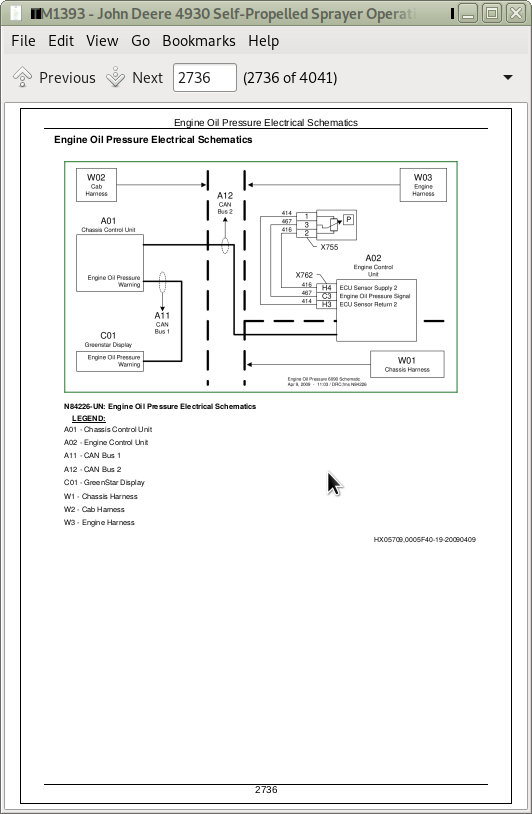
15BW - Warning - Engine Oil Pressure Diagnostics
Engine Oil Pressure Electrical Schematics
Theory of Operation
Warning - Engine Oil Pressure Diagnostics
15BX - Warning - Engine Speed Diagnostics
Engine Speed Electrical Schematics
Theory of Operation
Warning - Engine Speed Diagnostics
15BY - Warning - Engine Temperature Diagnostics
Electrical Schematics
Theory of Operation
Warning - Engine Temperature Diagnostics
15BZ - Wheel Speed Sensor Diagnostics
Theory of Operation
Wheel Speed Sensor Diagnostics
Wheel Speed Sensor Schematic (Serial Number -004000)
Wheel Speed Sensor Schematic (Serial Number 004001- )
15C - Air Quality Diagnostics - Automatic Temperature Control
Air Quality Schematic - Automatic Temperature Control
Automatic Temperature Control (ATC) Diagnostics
15CA - Wiper Diagnostics
Theory of Operation
Wiper Diagnostics
Wiper Schematic
15D - Auxiliary Power Strip Diagnostics
Auxiliary Power Strip Diagnostics
Auxiliary Power Strip Schematic
Theory of Operation
15E - Backup Alarm
Backup Alarm Schematic
15F - Boom Fold357200242Unfold Diagnostics
Boom Fold342200224Unfold Diagnostics
Boom Fold342200224Unfold Schematic (Serial Number 342200223004000)
Boom Fold342200224Unfold Schematic (Serial Number 004001- )
Theory of Operation
15G - Boom Leveling Diagnostics
Auto Boom Leveling Schematic (Serial Number -004000)
Auto Boom Leveling Schematic (Serial Number 004001- )
Boom Leveling Diagnostics
Boom Leveling Schematic
Boom Leveling Theory of Operation
15H - Boom Raise-Lower Diagnostics
Boom Raise-Lower Diagnostics
Boom Raise Lower Schematic (Serial Number -004000)
Boom Raise Lower Schematic (Serial Number 004001- )
Boom Raise-Lower Theory of Operation
15I - BoomTrac Pro Auto Boom Leveling Diagnostics
Auto Boom Leveling Schematic (Serial Number -004000)
Auto Boom Leveling Schematic (Serial Number 004001- )
Boom Leveling Diagnostics
Boom Raise-Lower Diagnostics
Boom Raise Lower Schematic (Serial Number -004000)
Boom Raise Lower Schematic (Serial Number 004001- )
Boom Raise-Lower Theory of Operation
BoomTrac Pro Leveling System Electrical Diagnostics
BoomTrac Pro Theory of Operation
15J - CAN Bus Diagnostics
CAN Bus 1 Diagnostics (Serial Number -004000)
CAN Bus 1 Diagnostics (Serial Number 004001- )
CAN Bus 2 Diagnostics (Serial Number -004000)
CAN Bus 2 Diagnostics (Serial Number 004001- )
CAN Bus 3 Diagnostics (Serial Number -004000)
CAN Bus 3 Diagnostics (Serial Number 004001- )
CAN Bus Schematic (Serial Number -004000)
CAN Bus Schematic (Serial Number 004001- )
Theory of Operation
15K - CAN Multifunction Control Handle Diagnostics
CAN Multifunction Control Handle Diagnostics
Multifunction Control Handle Schematic
Multifunction Control Handle Theory of Operation
15L - Caution Lamp Diagnostics
Caution Lamp Diagnostics
Caution Lamp Schematic
Theory of Operation
15M - Charging System Diagnostics
Charging System Diagnostics
Charging System Schematic
Temperature Correction Chart
Theory of Operation
15N - Chassis Controller (CCU) Unit Power Diagnostics
Chassis Controller (CCU) Unit Power Diagnostics
Chassis Controller (CCU) Unit Power Schematic
Theory of Operation
15O - Dome Lights Diagnostics
Dome Lights Diagnostics
Dome Lights Schematic
Theory of Operation
15P - Drivetrain Status Diagnostics
Drivetrain Status Diagnostics
Drivetrain Status Schematic
Theory of Operation
15Q - Dry Spreader Electrical Diagnostics
Dry Spreader Control Schematic (John Deere Control Unit)
Dry Spreader Control Schematic (New Leader Control Unit)
Dry Spreader Electrical Diagnostics (John Deere Control Unit)
Dry Spreader Electrical Diagnostics (New Leader Control Unit)
Dry Spreader Theory of Operation (John Deere Control Unit)
Dry Spreader Theory of Operation (New Leader Control Unit)
15R - Dry Rate Control Unit Power Diagnostics
Dry Rate Control Unit (DRC) Theory of Operation
Dry Rate Control Unit Power Diagnostics
Dry Rate Control Unit Power Schematic
15S - Electric Fuel Pump Diagnostics
Electrical Schematic
Electric Fuel Pump Diagnostics
Theory of Operation
15T - Engine Control Unit - Overall Diagnostics
ECU Electrical Schematic
Engine Control Unit - Overall Diagnostics
Theory of Operation
15U - Engine and Fuel Control Diagnostics
Engine and Fuel Control Diagnostics
Engine and Fuel Control Electrical Schematics
Engine and Fuel Control Theory of Operation
15V - Foam Marker (Dual Drop) Diagnostics
Foam Marker (Dual Drop) Diagnostics (S.N. 342200224013000)
Foam Marker (Dual Drop) Diagnostics (S.N. 013001342200224 )
Foam Marker (Dual Drop) Electrical Theory of Operation
Foam Marker (Dual Drop) Schematic
15W - Foam Marker (Single Drop) Diagnostics
Foam Marker (Single Drop) Diagnostics (S.N. 342200224013000)
Foam Marker (Single Drop) Diagnostics (S.N. 013001342200224 )
Foam Marker (Single Drop) Electrical Theory of Operation
Foam Marker (Single Drop) Schematic
15X - Fuel Level Sensor Diagnostics
Fuel Level Sensor Diagnostics
Schematic
Theory of Operation
15Y - CAN Bus Diagnostics-AMS Applications
CAN Bus Diagnostics-AMS Applications
CAN Bus Schematic
Theory of Operation
15Z - GreenStar AutoTrac Diagnostics
AutoTrac Diagnostics (Serial Number -004000)
AutoTrac Diagnostics (Serial Number 004001- )
AutoTrac Schematics (Serial Number ( -004000)
AutoTrac Schematics (Serial Number 004001- )
AutoTrac Theory of Operation (Serial Number -004000)
AutoTrac Theory of Operation (Serial Number 004001- )
20 - Connector Information
Connector Number Designations
X100 - X199 342200224 Connector Number Information
X200 - X299 342200224 Connector Number Information
X400 - X499 342200224 Connector Number Information
X500 - X599 342200224 Connector Number Information
X600 - X699 342200224 Connector Number Information
X700 - X799 342200224 Connector Number Information
250 - Power Train Diagnosis and Tests
05 - General Information
General Information
Hydrostatic Drive Specifications
Hydrostatic System Component Glossary
Power Train Operational Checkout
10 - Test Procedures
Adjust Charge Pressure Relief Valve on Front Pump
Adjust Hydrostatic Forward High Pressure
Hydrostatic Pumps Pressure Difference Test
Hydrostatic Pump Stall Test
Independent Front and Rear Charge Pump Test
Independent Front and Rear Hydrostatic Main Pump Test
Servo Valve Pressure Test
Test - Case Drain Flow of FRONT Motors For Hydrostatic Pumps
Test - Case Drain Flow of REAR Motors For Hydrostatic Pumps
Test Charge Pressure Relief Valve
Test - Forward and Reverse Charge Pressure
Test Hydrostatic System with All Wheel Motor Solenoids Unplugged
Test Hydrostatic Wheel Motor with One Motor Electrically Connected
15A - Final Drive Diagnostics
Final Drive Diagnostics
Final Drive Schematic
Theory of Operation
15B - Hydrostatic Drive Diagnostics
Hydrostatic Drive Diagnostics
Hydrostatic Schematic
Theory of Operation
20 - Component Location
Component Location
260 - Brake System Diagnosis and Tests
05 - General Information
General Information
10 - Brake System Tests
Bleeding Service Brakes
Park Brake Release Pressure Test
Park Brake Wheel Hub Release Test
Service Brake Pressure Test - Using Pressure Gauge
15A - Park Brake Diagnostics
Park Brake Diagnostics
Park Brake Schematic
Theory of Operation
15B - Service Brake Diagnostics
Service Brake Diagnostics
Service Brake Schematic
Theory of Operation
20 - Component Location
Component Location
270 - Hydraulic System Diagnosis and Tests
05 - General Information
General Information
Hydraulic Operational Checks
Hydraulic System Component Glossary
Hydraulic System Specifications
10 - Test Procedures and Adjustments
Adjust Conveyor Valve Flow
Boom Cycle Times
Hydraulic Pump Auxiliary Flow Test
Test and Adjust Compensator Pressure
Test and Adjust Standby Pressure
Test Full Boom Breakaway System Pressure
Test Hydraulic Load Sense System
Test Proportional Valve and Solution Pump Hydraulic Flow Rate
15A - Hydraulic System Basic Diagnostics
Basic Hydraulic System Schematic
Hydraulic System Basic Diagnostics
Theory of Operation
15B - Boom Fold and Unfold Diagnostics
Boom Fold and Unfold Diagnostics
Boom Fold and Unfold Schematic
Theory of Operation
15C - Boom Left-Hand Leveling Diagnostics
Boom Left-Hand Leveling Diagnostics
Boom Leveling Hydraulic Schematic
Boom Leveling Theory of Operation
15D - Boom Raise and Lower Diagnostics
Boom Raise and Lower Diagnostics
Boom Raise and Lower Hydraulic Schematic
Theory of Operation
15E - Boom Right-Hand Leveling Diagnostics
Boom Leveling Hydraulic Schematic
Boom Leveling Theory of Operation
Boom Right-Hand Leveling Diagnostics
15F - Dry Application System Checkout
Dry Application System Checkout
Dry Spreader Hydraulic Theory of Operation
15G - Full Boom Breakaway Hydraulic Diagnostics
Full Boom Breakaway Hydraulic Diagnostics
Full Boom Breakaway Schematic
Theory of Operation
15H - Ladder Diagnostics
Ladder Diagnostics
Ladder Schematic
Theory of Operation
15I - Load Command Hydraulic Diagnostics
Load Command Hydraulic Diagnostics
Load Command Hydraulic Schematic
Load Command Hydraulic Theory of Operation
15J - Solution Pump Hydraulic Diagnostics
Solution Pump Hydraulic Diagnostics
Solution Pump Motor Hydraulic Schematic
Theory of Operation
20 - Combination Valve Port Locations
Combination Valve Port Locations
Hydraulic Components Location
275 - Tread Adjust System
05 - General Information
General Information
Tread Adjust Operation Checks
Tread Adjust System Component Identification
10 - Test Procedures and Adjustments
Adjust Tread Adjust Shims
Tread Adjust Cylinder Leakage Test
15 - Tread Adjust Diagnostics
Theory of Operation
Tread Adjust Diagnostics
Tread Adjust Hydraulic Schematic
Tread Adjust Valve Block
20 - Component Location
Tread Adjust Hydraulic Component Location
280 - Steering System Diagnosis and Tests
05 - General Information
General Information
Steering System Component Identification
Steering System Operation Checks
Steering System Specifications
10 - Steering Test Procedure and Adjustment
Adjust Front Axle Toe-In
Adjust Load Sense Pressure Relief on AUTO - TRAC Steering Valve
Check Front Axle Toe-In
Steering Cylinder Leak Test
Steering Valve Load Sense Relief Test
Steering Valve Pressure Test
Toe Control Valve Relief Test
15 - Steering System Diagnostics
Steering Hydraulic Schematic
Steering System Diagnostics
Theory of Operation
20 - Component Location
Steering System Component Location
290 - Operator Station Diagnosis and Tests
05 - General Information
Air Conditioning System Specifications
General Information
10 - Test Procedure and Adjustment
AC - System Pressure Test
AC - System Static Pressure Test
AC - Temperature Drop Test
Air Conditioning - Preliminary Checks
Pressure and Leak Testing The Air Conditioning System
15 - Air Conditioning and Heating System Diagnostics
AC - Manual Control Operational Check
Air Conditioning 342200224 ATC Operational Check
Air Conditioning Diagnostics
Air Conditioning Schematic
Theory of Operation
20 - System Components
Air Conditioning System Components
300 - Solution System Diagnosis and Tests
05 - General Information
General Information
10 - Test Procedures and Adjustments
Check Flowmeter Calibration
Checking Solution Pump Dead Head Pressure
Chemicals, avoid contact
Load Command Operation Test
Solution System Checks
Solution System Valve Mechanical Check
15A - Solution System Diagnostics
Solution System Eductor Diagnostics
Solution System Erratic Rate Diagnostics
Solution System Loading Diagnostics
Solution System Overall Diagnostics
Solution System Over or Under Application Diagnostics
Solution System Pressure Diagnostics
Solution System Rinse Diagnostics
Solution System Schematic
Theory of Operation
15B - Load Command Diagnostics
Load Command Diagnostics
Load Command Schematic
Load Command Theory of Operation
20 - Component Location
Solution System Component Location
310 - Foamer Diagnosis and Tests
05 - General Information
Foam Marker General Information
Foam Marker System Operational Checks (On Board Air Supply) (S.N. 342200224013000)
10 - Test Procedures and Adjustments
Foam Marker Test Procedures and Adjustments (S.N. 342200224013000)
15A - Foam Marker Diagnostic Procedure (S.N. 342200224013000)
Foam Marker Diagnostic Procedure (S.N. 342200224013000)
Foam Marker Schematics (S.N. 342200224013000)
Foam Marker Theory of Operation (S.N. 342200224013000)
15B - Foam Marker Diagnostic Procedure (S.N. 013001342200224 )
Foam Marker Diagnostic Procedure (S.N. 013001342200224 )
Foam Marker Schematics (S.N. 013001342200224 )
Foam Marker Theory of Operation (S.N. 013001342200224 )
399 - Service Tools
38H1146 342200224 -6 ORFS Plug
38H1415 342200224 -6 ORFS Cap
DFRW130342200224Relay Circuit Test Lead
DFRW167 342200224 Water Valve Test Harness
JDG10393 Support Stand
JDG10477 342200224 Wheel Motor Test Harness
JDG10949 342200224 Sprayer Jack
JT02156A 342200224 Digital Pressure and Temperature Analyzer
JT02158 342200224 Digital Pressure and Temperature Analyzer
JT02159 342200224 20 ft Cable
JT02160 342200224 10,000 PSI Transducer
JT02161 342200224 3500 kPa (350 bar) (500 psi) Transducer
JT02162 342200224 5000 PSI Transducer
JT03413 342200224 Supplemental Flow Test Kit
JT05418 342200224 Industrial Flow Test Kit
JT05690 342200224 Straight Fitting (1 1 _ 16-12 M 37302260 x 1 3 _ 16-12 F ORFS)
JT05709 342200224 Reflective Tape
JT05719 342200224 Hand Held Digital Tachometer
JT05845 342200224 2-Speed Hand Pump
JT07148342200224Digital Hydraulic Tester
JT07253 342200224 Infrared Temperature Gun
JT07260 342200224 ORFS Adapter Hydraulic Test Kit
John Deere Self-Propelled Sprayer 4930 Diagnosis and Test Service Manual (TM1393)
![]()