
John Deere 4940 Self-Propelled Sprayers Diagnosis and Tests Service Manual (TM113519)
Complete Diagnosis and Test manual with Electrical Wiring Diagrams for John Deere 4940 Self-Propelled Sprayers (PIN Prefix N0 or 1N0), with all the workshop information to maintain, diagnose, and rebuild like professional mechanics.
John Deere 4940 Self-Propelled Sprayers workshop Diagnostics and Test manual includes:
* Numbered table of contents easy to use so that you can find the information you need fast.
* Detailed sub-steps expand on repair procedure information
* Numbered instructions guide you through every repair procedure step by step.
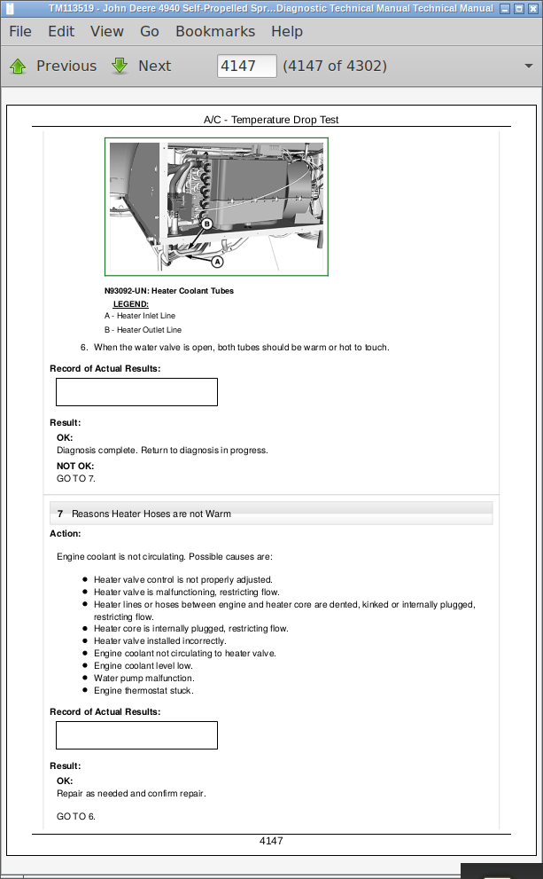
* Troubleshooting and electrical service procedures are combined with detailed wiring diagrams for ease of use.
* Notes, cautions and warnings throughout each chapter pinpoint critical information.
* Bold figure number help you quickly match illustrations with instructions.
* Detailed illustrations, drawings and photos guide you through every procedure.
* Enlarged inset helps you identify and examine parts in detail.
TM113519 - John Deere 4940 Self-Propelled Sprayers Technical Manual (Operation and Test).PDF
TM113519 - John Deere 4940 Self-Propelled Sprayers Technical Manual (Operation and Test).epub
Total Pages: 5,012 pages
File Format: PDF/EPUB/MOBI/AZW (PC/Mac/Android/Kindle/iPhone/iPad; bookmarked, ToC, Searchable, Printable)
Language: English
MAIN SECTIONS
Diagnostic Trouble Codes (DTC)
Boom Hydraulic Control Unit (BHC)
Chassis Control Unit (CCU)
Dry Rate Control Unit (DRC)
Engine Control Unit (ECU) - iT4 Engine
Engine Control Unit (ECU) - Tier 2 Engine
Load Command Control Unit (LCC)
Spray Rate Control Unit (SRC)
Steering System Control Unit (XMC)
Steering System Control Unit (XSC)
Observable Symptoms and System Diagnostics
Engine
Fuel and Air Intake
Electrical
Control Units
Power Train
Steering and Brakes
Hydraulic and Suspension
Solution System
Dry Application System
Operator Station
Engine
Engine Component Location
Fuel and Air Intake
Fuel and Air Intake Component Location
Electrical
General Information
Theory of Operation
- Starting, Charging, and Power Distribution
- Lighting
- Cab Electrical
- Application System
- GreenStar
- Engine Electrical
- Power Train Electrical
- Hydraulic Electrical
- Display
- CAN Bus
Starting, Charging, and Power Distribution Schematics
Lighting Schematics
Cab Electrical Schematics
Application System Schematics
GreenStar Schematics
Engine Electrical Schematics
Power Train Electrical Schematics
Hydraulic Electrical Schematics
Display Schematics
CAN Bus Schematics
Starting, Charging, and Power Distribution Diagnostics
Lighting Diagnostics
Cab Electrical Diagnostics
Application System Diagnostics and Tests
GreenStar Diagnostics and Tests
Engine Electrical Diagnostics and Tests
Power Train Electrical Diagnostics and Tests
Hydraulic Electrical Diagnostics and Tests
Display Diagnostics and Tests
CAN Bus Diagnostics and Tests
Control Units
Electrical Connector Location
Power Train
Power Train Component Location
Steering and Brakes
Hydraulic, Suspension, and Pneumatics
Hydraulic, Suspension, and Pneumatics Component Location
Application System
Application System Component Location
Operator Station
Operator Station Component Location
Special Tools
tm113519 - 4940 Self-Propelled Sprayer Diagnostic Technical Manual
Table of Contents
Foreword
Section 210: General Information
Group 5: Safety
Recognize Safety Information
Understand Signal Words
Follow Safety Instructions
Replace Safety Signs
Prepare for Emergencies
Wear Protective Clothing
Protect Against Noise
Practice Safe Maintenance
Park Machine Safely
Work in Clean Area
Avoid High-Pressure Fluids
Handle Electronic Components and Brackets Safely
Avoid Heating Near Pressurized Fluid Lines
Decommissioning — Proper Recycling and Disposal of Fluids and Components
Use Proper Tools
Work In Ventilated Area
Handle Agricultural Chemicals Safely
Handle Agricultural Chemicals Safely
Group 10: Machine Specifications
Machine Specifications
Group 15: Machine Dimensions
Machine Dimensions
Group 20: Component Serial Number Locations
Identification Numbers
Section 211: Diagnostic Trouble Codes (DTC)
Group 10A: Automatic Temperature Control Unit (ATC)
ATC 000170.03 - Cab Temperature Sensor Circuit Voltage High
ATC 000170.04 - Cab Temperature Sensor Circuit Voltage Low
ATC 000628.12 - ATC Programming
ATC 000639.14 - ATC CAN Error Limit Exceeded
ATC 000871.03 - Refrigerant Pressure Sensor Circuit Voltage High
ATC 000871.04 - Refrigerant Pressure Sensor Circuit Voltage Low
ATC 000923.03 - Circulation Blower Motor Circuit Voltage High
ATC 000923.04 - Circulation Blower Motor Circuit Voltage Low
ATC 000923.12 - Circulation Blower Motor Driver Circuit Fault
ATC 001546.03 - Water Valve Position Sensor Circuit Voltage High
ATC 001546.04 - Water Valve Position Sensor Circuit Voltage Low
ATC 001547.03 - Evaporator Temperature Sensor Circuit High Voltage
ATC 001547.04 - Evaporator Temperature Sensor Circuit Voltage Low
ATC 001548.03 - Outlet Air Temperature Sensor Circuit High Voltage
ATC 001548.04 - Outlet Air Temperature Sensor Circuit Voltage Low
ATC 001549.03 - Water Valve Motor Circuit Voltage High
ATC 001549.04 - Water Valve Motor Circuit Voltage Low
ATC 001549.07 - Heater Valve Fault
ATC 001549.13 - Water Valve Motor Not Calibrated
ATC 001551.03 - Pressurizer Blower Control Relay Driver Circuit High
ATC 001551.04 - Pressurizer Blower Control Relay Driver Circuit Low
ATC 002000.09 - ECU Message Missing
ATC 003509.03 - ATC Sensor Supply Voltage High
ATC 003509.04 - ATC Sensor Supply Low
ATC 003509.06 - ATC Sensor Supply Voltage Low
ATC 520870.02 - ATC Calibration Fault/Data Invalid
ATC 520871.02 - ATC Calibration Fault/Data Invalid
ATC 520872.02 - ATC Calibration Fault/Data Invalid
ATC 523848.03 - Air Flow Mode Motor Circuit Voltage High
ATC 523848.04 - Air Flow Mode Motor Circuit Voltage Low
ATC 523848.05 - Air Flow Mode Motor Circuit Current Low
ATC 523848.06 - Air Flow Mode Motor Circuit Current High
ATC 523848.07 - Adjusting Motor for Air Distribution Fault
ATC 523848.13 - Air Flow Mode Motor Not Calibrated
ATC 524202.03 - Ambient Temperature Sensor Circuit Voltage High
ATC 524202.04 - Ambient Temperature Sensor Circuit Voltage Low
Group 10B: Boom Hydraulic Control Unit (BHC)
BHC 000158.00 - Boom Hydraulics Control Unit Supply Voltage High
BHC 000158.01 - Boom Hydraulics Control Unit Supply Voltage Low
BHC 000630.02 - Boom Hydraulics Controller Calibration Fault
BHC 522316.00 - BoomTrac Pro Sensor C Height Value High
BHC 522316.01 - BoomTrac Pro Sensor C Height Value Low
BHC 522316.12 - BoomTrac Pro Sensor C Communication Fault
BHC 522316.13 - Boom Return to Height Sensor Calibration Fault
BHC 522372.00 - BoomTrac Pro Sensor R1 Height Value High
BHC 522372.01 - BoomTrac Pro Sensor R1 Height Value Low
BHC 522372.12 - BoomTrac Pro Sensor R1 Communication Fault
BHC 522372.13 - Right Inner Boom Fold Sensor Calibration Fault
BHC 522377.00 - BoomTrac Pro Sensor R2 Height Value High
BHC 522377.01 - BoomTrac Pro Sensor R2 Height Value Low
BHC 522377.12 - BoomTrac Pro Sensor R2 Fault
BHC 522377.13 - Right Outer Boom Fold Sensor Calibration Fault
BHC 522378.00 - BoomTrac Pro Sensor L1 Height Value High
BHC 522378.01 - BoomTrac Pro Sensor L1 Height Value Low
BHC 522378.12 - BoomTrac Pro Sensor L1 Communication Fault
BHC 522378.13 - Left Inner Boom Fold Sensor Calibration Fault
BHC 522380.00 - BoomTrac Pro Sensor L2 Height Value High
BHC 522380.01 - BoomTrac Pro Sensor L2 Height Value Low
BHC 522380.12 - BoomTrac Pro Sensor L2 Communication Fault
BHC 522380.13 - Left Outer Boom Fold Sensor Calibration Fault
BHC 523461.03 - Boom Roll Sensor Circuit Fault
BHC 523467.14 - Left Boom Fold Sensor in Folded Position While BoomTrac Pro Active
BHC 523470.14 - Right Boom Fold Sensor in Folded Position While BoomTrac Pro Active
BHC 523477.01 - Boom Center Frame Lower Valve Circuit Fault
BHC 523477.06 - Boom Center Frame Lower Valve Circuit Fault
BHC 523478.05 - Boom Center Frame Raise Valve Circuit Fault
BHC 523478.06 - Boom Center Frame Raise Valve Circuit Fault
BHC 523479.05 - Left Boom Tilt Down Valve Circuit Fault
BHC 523479.06 - Left Boom Tilt Down Valve Circuit Fault
BHC 523480.05 - Right Boom Tilt Down Valve Circuit Fault
BHC 523480.06 - Right Boom Tilt Down Valve Circuit Fault
BHC 523481.05 - Left Boom Tilt Up Valve Circuit Fault
BHC 523481.06 - Left Boom Tilt Up Valve Circuit Fault
BHC 523482.05 - Right Boom Tilt Up Valve Circuit Fault
BHC 523482.06 - Right Boom Tilt Up Valve Circuit Fault
BHC 523612.12 - BoomTrac Pro Resume Switch Communication Fault
Group 10C: Chassis Control Unit (CCU)
CCU 000091.03 - Throttle Sensor Circuit Out of Range High
CCU 000091.04 - Throttle Sensor Circuit Out of Range Low
CCU 000096.01 - Fuel Level Low
CCU 000096.05 - Fuel Level Sensor Circuit Out Of Range Open
CCU 000096.06 - Fuel Level Sensor Circuit Out Of Range Low
CCU 000158.00 - Chassis Control Unit Supply Voltage High
CCU 000158.01 - Chassis Control Unit Supply Voltage Low
CCU 000630.02 - CCU EEPROM Checksum Failure
CCU 000767.02 - Multi-function Lever Reverse Switch Fault
CCU 000903.02 - Multi-function Lever Forward Switch Fault
CCU 001592.02 - Left Front Wheel Speed Fault
CCU 001593.02 - Right Front Wheel Speed Fault
CCU 001594.02 - Left Rear Wheel Speed Fault
CCU 001595.02 - Right Rear Wheel Speed Fault
CCU 001745.14 - Multi-function Lever Not In Park
CCU 002000.09 - Communication Fault
CCU 002225.09 - Communication Fault
CCU 002246.09 - Communication Fault
CCU 002602.01 - Hydraulic Oil Level Low
CCU 003695.05 - Exhaust Aftertreatment Switch Circuit Fault
CCU 003696.03 - Exhaust Aftertreatment Switch Circuit Fault
CCU 522345.03 - Multi-function Lever Propulsion Sensor 1 Circuit Fault
CCU 522345.04 - Multi-function Lever Propulsion Sensor 1 Fault
CCU 523953.13 - Multi-function Lever Propulsion Sensor Calibration Fault
CCU 524279.31 - Operator Out of Seat
Group 10D: Dry Rate Control Unit (DRC)
DRC 000158.00 - Dry Rate Controller Supply Voltage High
DRC 000158.10 - Dry Rate Controller Supply Voltage Low
DRC 000630.20 - Dry Rate Controller Calibration Fault
DRC 002071.09 - Communication Fault
DRC 003509.00 - Sensor Voltage High
DRC 003509.01 - Sensor Voltage Low
DRC 003509.04 - Sensor Voltage Open
DRC 520247.02 - Fertilizer Product Belt Not Operating Correctly
DRC 523394.02 - Spinners Not Operating Correctly
Group 10E: Engine Control Unit (ECU) — iT4 Engine
ECU 000027.03 - EGR Valve Position Voltage OOR High
ECU 000027.04 - EGR Valve Position Voltage OOR Low
ECU 000027.07 - EGR Valve Not Responding or Out of Adjustment
ECU 000051.14 - Sensed Position of EGR is Open and Air Throttle is Closed at Power-up
ECU 000051.03 - Air Throttle Valve Position Voltage OOR High
ECU 000051.04 - Air Throttle Valve Position Voltage OOR Low
ECU 000051.07 - Air Throttle Not Responding or Out of Adjustment
ECU 000091.04 - Throttle Message Missing or Invalid
ECU 000094.03 - Low Pressure Fuel Pressure Signal Out of Range High
ECU 000094.04 - Low Pressure Fuel Signal Out of Range Low
ECU 000094.16 - Fuel Pressure High Moderately Severe Level
ECU 000094.17 - Low Pressure Fuel Signal Slightly Low
ECU 000094.18 - Fuel Pressure Low Moderately Severe Level -20kPa for Greater than 5 seconds
ECU 000096.03 - Fuel Level Sensor OORH
ECU 000096.04 - Fuel Level Sensor OORL
ECU 000097.16 - Water-in-Fuel Detected
ECU 000097.03 - Water-in-Fuel Signal Out of Range High
ECU 000097.04 - Water-in-Fuel Signal Out of Range Low
ECU 000100.01 - Engine Oil Pressure Signal Extremely Low
ECU 000100.02 - Oil Pressure Detected at Zero Engine Speed
ECU 000100.03 - Engine Oil Pressure Input Voltage High
ECU 000100.04 - Engine Oil Pressure Signal Out of Range Low
ECU 000100.18 - Engine Oil Pressure Signal Moderately Low
ECU 000102.03 - Intake Manifold Pressure Signal Out of Range High
ECU 000102.04 - Intake Manifold Pressure Signal Out of Range Low
ECU 000102.07 - Manifold Air Pressure Sensor Reading does not Match Engine Conditions
ECU 000103.00 - Turbo Speed Signal Extremely High
ECU 000103.02 - Turbo Speed Data Incorrect
ECU 000103.05 - Turbo Speed Sensor Circuit has High Resistance
ECU 000105.00 - Intake Manifold Air Temperature Signal Extremely High
ECU 000105.03 - Intake Manifold Air Temperature Signal Out of Range High
ECU 000105.04 - Intake Manifold Air Temperature Signal Out of Range Low
ECU 000105.15 - Intake Manifold Air Temperature Signal Slightly High
ECU 000105.16 - Intake Manifold Air Temperature Signal Moderately High
ECU 000107.00 - Air Filter Pressure Differential Extremely High
ECU 000107.15 - Engine Air Filter is Restricted
ECU 000107.16 - Engine Air Filter is Restricted
ECU 000108.02 - Barometric Pressure Signal Invalid
ECU 000108.07 - Barometric Pressure Sensor Fault
ECU 000109.01 - Coolant Pressure is Low
ECU 000109.03 - Coolant Pressure Voltage OOR High
ECU 000109.01 - Coolant Pressure Voltage OOR Low
ECU 000109.17 - Low Coolant Pressure for One Extended Run Period
ECU 000109.18 - Low Coolant Pressure
ECU 000109.31 - Low Coolant Pressure
ECU 000110.00 - Engine Coolant Temperature Signal Extremely High
ECU 000110.03 - Engine Coolant Temperature Signal Out of Range High
ECU 000110.04 - Engine Coolant Temperature Signal Out of Range Low
ECU 000110.15 - Engine Coolant Temperature Signal Slightly High
ECU 000110.16 - Engine Coolant Temperature Signal Moderately High
ECU 000110.17 - Engine Coolant Temperature Signal Slightly Low
ECU 000111.01 - Engine Coolant Level Extremely Low
ECU 000111.07 - Switches Indicate that Coolant Level is Below the Loss Switch but not Below the Service Switch
ECU 000111.17 - Coolant Level Below the Service Switch
ECU 000111.18 - Coolant Level-is too Low
ECU 000152.12 - Unexpected Reset in Bootblock
ECU 000152.14 - Unexpected Reset in Watchdog
ECU 000152.16 - Unexpected Reset
ECU 000157.01 - Fuel Rail Pressure Signal Extremely Low
ECU 000157.03 - Fuel Rail Pressure Signal Out of Range High
ECU 000157.04 - Fuel Rail Pressure Signal Out of Range Low
ECU 000157.10 - Fuel Rail Pressure Rate of Change Abnormal
ECU 000157.16 - Fuel Rail Pressure Signal Moderately High
ECU 000157.17 - Fuel Rail Pressure Not Developed
ECU 000157.18 - Fuel Rail Pressure Signal Moderately Low
ECU 000157.12 - ECU Cannot Power Down
ECU 000168.01 - Supply Voltage OOR too Low. Most Severe Level.
ECU 000168.16 - Battery Voltage Above Normal Operating Level
ECU 000168.18 - Battery Voltage Below Normal Operating Level
ECU 000174.00 - Fuel Temperature Signal Extremely High
ECU 000174.03 - Fuel Temperature Signal Out of Range High
ECU 000174.04 - Fuel Temperature Signal Out of Range Low
ECU 000174.16 - Fuel Temperature Signal Moderately High
ECU 000189.31 - A Condition Exists Which is Causing the Engine to Derate
ECU 000190.00 - Engine Speed Extremely High
ECU 000237.02 - VIN Security Data Invalid
ECU 000237.13 - VIN Option Code Security Data Conflict
ECU 000237.31 - VIN Security Data Missing
ECU 000412.00 - EGR Temperature Signal Extremely High
ECU 000412.16 - EGR Temperature Signal Moderately High
ECU 000412.03 - EGR Temperature Signal Out of Range High
ECU 000412.04 - EGR Temperature Signal Out of Range Low
ECU 000412.15 - EGR Temperature Signal Slightly High
ECU 000611.03 - Injector Shorted to Power
ECU 000611.04 - Injector Shorted to Ground
ECU 000612.03 - Short to Battery on the Injector Lines
ECU 000612.04 - Short to Ground on the Injector Lines
ECU 000623.12 - ECU EEPROM Error
ECU 000623.13 - ECU Boot Block Error
ECU 000629.11 - Too High Current Draw on Binary Chip, Over Temp
ECU 000636.02 - Camshaft Sensor Signal Invalid
ECU 000636.05 - Camshaft Sensor Circuit has High Resistance
ECU 000636.06 - Camshaft Sensor Circuit has Low Resistance
ECU 000636.08 - Camshaft Sensor Signal Missing
ECU 000636.10 - Camshaft Signal Rate of Change Abnormal
ECU 000637.02 - Crankshaft Position Sensor Signal Invalid
ECU 000637.05 - Engine Position Sensor Circuit has High Resistance
ECU 000637.06 - Engine Position Sensor Circuit has Low Resistance
ECU 000637.07 - Crankshaft Position and Position Signals Out of Sync
ECU 000637.08 - Crankshaft Position Timing Sensor Signal Missing
ECU 000637.10 - Crankshaft Position Signal Rate of Change Abnormal
ECU 000641.05 - The VTG Actuator Power Driver is Open Circuit
ECU 000641.06 - VGT Mappable Output Short Circuit
ECU 000641.07 - VTG SRA Learn Failure
ECU 000641.13 - VGT Actuator Learn Error
ECU 000641.15 - VTG Fully Open Position Error
ECU 000641.17 - VTG Fully Closed Position Error
ECU 000647.05 - Engine Fan Drive Circuit has High Resistance
ECU 000647.07 - Engine Fan Drive not Responding
ECU 000651.02 - Injector #1 Part # Data Invalid
ECU 000651.05 - Injector #1 Circuit has High Resistance
ECU 000651.06 - Injector #1 Circuit has Low Resistance
ECU 000651.13 - Injector #1 Calibration Fault
ECU 000651.18 - The Injector Fuel Flow at Cylinder #1 is Low
ECU 000652.02 - Injector #2 Part # Data Invalid
ECU 000652.05 - Injector #2 Circuit has High Resistance
ECU 000652.06 - Injector #2 Circuit has Low Resistance
ECU 000652.13 - Injector #2 Calibration Fault
ECU 000652.18 - The Injector Fuel Flow at Cylinder #2 is Low
ECU 000653.02 - Injector #3 Part # Data Invalid
ECU 000653.05 - Injector #3 Circuit has High Resistance
ECU 000653.06 - Injector #3 Circuit has Low Resistance
ECU 000653.13 - Injector #3 Calibration Fault
ECU 000653.18 - The Injector Fuel Flow at Cylinder #3 is Low
ECU 000654.02 - Injector #4 Part # Data Invalid
ECU 000654.05 - Injector #4 Circuit has High Resistance
ECU 000654.06 - Injector #4 Circuit has Low Resistance
ECU 000654.13 - Injector #4 Calibration Fault
ECU 000654.18 - The Injector Fuel Flow at Cylinder #4 is Low
ECU 000655.02 - Injector #5 Part # Data Invalid
ECU 000655.05 - Injector #5 Circuit has High Resistance
ECU 000655.06 - Injector #5 Circuit has Low Resistance
ECU 000655.13 - Injector #5 Calibration Fault
ECU 000655.18 - The Injector Fuel Flow at Cylinder #5 is Low
ECU 000656.02 - Injector #6 Part # Data Invalid
ECU 000656.05 - Injector #6 Circuit has High Resistance
ECU 000656.06 - Injector #6 Circuit has Low Resistance
ECU 000656.13 - Injector #6 Calibration Fault
ECU 000656.18 - The Injector Fuel Flow at Cylinder #6 is Low
ECU 001075.02 - Data Received from Pump Indicates Loss of Communication to ECU
ECU 001075.04 - Electric Lift Pump for Engine Fuel Supply Circuit - Voltage Below Normal, or Shorted to Low Source
ECU 001075.06 - Razor Fuel Pump Current Above Normal or Grounded Circuit
ECU 001075.09 - No CAN Communication from Pump
ECU 001075.15 - Data Received from Pump Exceeds 130C for Greater than 55 seconds
ECU 001110.31 - Engine Protection Shutdown
ECU 001136.00 - ECU Temperature Signal Extremely High
ECU 001136.02 - ECU Temperature Invalid
ECU 001136.16 - ECU Temperature Signal Moderately High
ECU 001172.12 - Turbocharger Inlet Temperature Sensor Circuit Fault
ECU 001176.07 - Turbocharger Inlet Pressure Sensor Circuit Fault
ECU 001176.12 - Turbocharger Inlet Pressure Sensor Circuit Fault
ECU 001180.00 - Turbine Inlet Temperature Signal Extremely High
ECU 001180.16 - Turbine Inlet Temperature Signal Moderately High
ECU 001209.03 - Exhaust Pressure Sensor Circuit Voltage Above Normal, or Shorted to High Source
ECU 001209.04 - Exhaust Pressure Sensor Circuit Voltage Below Normal, or Shorted to Low Source
ECU 001209.07 - Exhaust Pressure Sensor Fault
ECU 001347.01 - Fuel Rail Pressure Very Low
ECU 001347.05 - High Pressure Fuel Pump Solenoid Circuit Has High Resistance
ECU 001347.06 - The Current to the High Pressure Pump SCV is Higher than Expected
ECU 001347.16 - Fuel Rail Pressure High
ECU 001347.18 - Fuel Rail Pressure Low
ECU 001550.05 - Air Conditioner Compressor Clutch Under-Current
ECU 001550.06 - Air Conditioner Compressor Clutch Over-Current
ECU 001568.02 - Torque Curve Selection Error
ECU 001569.31 - Engine Power Derate Condition Exists
ECU 001638.00 - Hydraulic Oil Temperature Exceeds 104C
ECU 001638.03 - Hydraulic Oil Temperature Sensor OORH
ECU 001638.04 - Hydraulic Oil Temperature Sensor OORL
ECU 001638.16 - Hydraulic Oil Temperature Exceeds 93C
ECU 001639.01 - Fan Speed Signal Extremely Low
ECU 001639.16 - Fan Speed Signal Moderately High
ECU 001639.18 - Fan Speed Signal Moderately Low
ECU 002602.03 - Hydraulic Oil Level Sensor OORH
ECU 002629.03 - Sensor Voltage OOR High
ECU 002629.04 - Sensor Voltage OOR Low
ECU 002630.00 - Charge Air Cooler Outlet Temperature Signal Extremely High
ECU 002630.03 - Charge Air Cooler Outlet Temperature Signal Out of Range High
ECU 002630.04 - Charge Air Cooler Outlet Temperature Signal Out of Range Low
ECU 002630.15 - Charge Air Cooler Outlet Temperature Signal Slightly High
ECU 002630.16 - Charge Air Cooler Outlet Temperature Signal Moderately High
ECU 002659.02 - Mismatch between Delta T and Delta P EGR Flow Models
ECU 002659.03 - EGR Delta Pressure Sensor Voltage OORH
ECU 002659.04 - EGR Delta Pressure Sensor Voltage OORL
ECU 002659.14 - EGR Flow Rate Error Indicator
ECU 002659.15 - EGR Mass Flow Rate Data Slightly High
ECU 002659.17 - EGR Mass Flow Rate Data Slightly Low
ECU 002790.16 - Calculated Compressor Outlet Temperature Moderately High
ECU 002791.05 - EGR valve circuit Current Below Normal or Open Circuit
ECU 002791.06 - EGR Valve Circuit Current Above Normal or Grounded Circuit
ECU 002791.07 - EGR Valve not Reaching Expected Position
ECU 002791.13 - EGR Valve Calibration Change Error
ECU 002795.02 - VGT Calibration Version Invalid
ECU 002795.03 - VGT Vane Position Signal Out of Range High
ECU 002795.04 - VGT Vane Position Signal Out of Range Low
ECU 002795.07 - VGT Actuator not Reaching Expected Position
ECU 002795.10 - VGT Position Actuator Fault
ECU 002795.13 - VGT Calibration Error
ECU 002797.03 - Injector High Voltage Supply #1 Out of Range High
ECU 002797.05 - Injector High Voltage Supply #1 Circuit High Resistance
ECU 002797.06 - Injector High Voltage Supply #1 Circuit Low Resistance
ECU 002798.03 - Injector High Voltage Supply #2 Out of Range High
ECU 002798.05 - Injector High Voltage Supply #2 Circuit High Resistance
ECU 002798.06 - Injector High Voltage Supply #2 Circuit Low Resistance
ECU 003246.00 - Very High DPF Outlet Temperature
ECU 003246.12 - DPF Outlet Temperature Error
ECU 003251.00 - DPF Differential Pressure Signal not Responding
ECU 003251.02 - DPF Differential Pressure Signal Invalid
ECU 003251.03 - DPF Differential Pressure Signal Out of Range High
ECU 003251.04 - DPF Differential Pressure Signal Out of Range Low
ECU 003353.31 - Alternator Without Function. Check for Broken Drive Belt.
ECU 003464.05 - The Current to the Air Throttle Valve is Less than Expected
ECU 003464.06 - The Current to the Air Throttle Valve is Higher than Expected
ECU 003464.07 - Air Throttle not Responding or Out of Adjustment
ECU 003464.13 - Air Throttle Out of Calibration
ECU 003471.03 - Fuel Dosing Shutoff Valve Circuit is Shorted to the Battery
ECU 003471.04 - Fuel Dosing Control Valve Circuit is Shorted to Ground
ECU 003471.05 - The Current to the Fuel Dosing Control Valve is Less than Expected
ECU 003471.07 - Dosing Outlet Pressure Mismatch
ECU 003471.11 - Pulse Duration is not as Long as Expected
ECU 003480.01 - Fuel Dosing Inlet Pressure Signal Extremely Low
ECU 003480.03 - Fuel Dosing Inlet Pressure Voltage OOR High
ECU 003480.04 - Fuel Dosing Inlet Pressure Voltage OOR Low
ECU 003480.07 - Measured Pressure is Mismatch from Desired for an Amount of Time
ECU 003480.18 - Fuel Dosing Inlet Pressure Lower than Expected
ECU 003482.03 - Fuel Dosing Shutoff Valve Circuit is Shorted to Battery
ECU 003482.04 - Fuel Dosing Shutoff Valve Circuit is Shorted to Ground
ECU 003482.05 - The Current to the Fuel Dosing Shutoff Valve is Less than Expected
ECU 003482.16 - Inlet Pressure Stays High After Commanding Shutoff Valve Closed
ECU 003509.03 - Sensor Supply #1 Voltage Out of Range High
ECU 003509.04 - Sensor Supply #1 Voltage Out of Range Low
ECU 003510.03 - Sensor Supply #2 Voltage Out of Range High
ECU 003510.04 - Sensor Supply #2 Voltage Out of Range Low
ECU 003511.03 - Sensor Supply #3 Voltage Out of Range High
ECU 003511.04 - Sensor Supply #3 Voltage Out of Range Low
ECU 003512.03 - Sensor Supply #4 Voltage Out of Range High
ECU 003512.04 - Sensor Supply #4 Voltage Out of Range Low
ECU 003513.03 - Sensor Supply #5 Voltage Out of Range High
ECU 003513.04 - Sensor Supply #5 Voltage Out of Range Low
ECU 003514.03 - Sensor Supply #6 Voltage Out of Range High
ECU 003514.04 - Sensor Supply #6 Voltage Out of Range Low
ECU 003556.16 - Nozzle Pressure Abnormally High During Dosing
ECU 003556.18 - Nozzle Pressure Abnormally Low During Dosing
ECU 003597.01 - Engine Control Unit High Voltage Fault
ECU 003695.14 - DPF Regeneration Required but Inhibit Switch OFF
ECU 003711.14 - Exhaust Filter Inlet Temperature not Reached. Active Exhaust Filter Cleaning Unavailable.
ECU 003711.31 - DOC Inlet Temperature Target not Reached During ETM
ECU 003719.00 - Soot at the Service Only Level
ECU 003719.10 - Soot Loading Rate too High
ECU 003719.13 - Exceeding the Number of Allowed Exhaust Filter Recovery
ECU 003719.14 - Exhaust Filter Restricted. Engine Power Limited. Initiate Service Cleaning.
ECU 003719.15 - DPF Soot Loading is in the High State
ECU 003719.16 - Soot at the Very High Level
ECU 003720.15 - Ash Load in Exhaust Filter is High
ECU 003720.16 - Ash Load in Exhaust Filter is High
ECU 003936.00 - Calculated Unintended Combustibles in DPF Extremely High
ECU 003936.15 - Calculated Unintended Combustibles in DPF Slightly High
ECU 003936.16 - Calculated Unintended Combustibles in DPF Moderately High
ECU 004077.03 - Fuel Dosing Outlet Pressure Voltage OOR High
ECU 004077.04 - Fuel Dosing Outlet Pressure Voltage OOR Low
ECU 004077.07 - Mismatch Between the Supply and Outlet Dosing Pressure Sensors
ECU 004490.12 - Turbocharger Compressor Inlet Sensor Fault
ECU 004765.00 - DOC Inlet Temperature Higher than Expected
ECU 004765.12 - DOC Inlet Temperature Error
ECU 004766.12 - DOC Outlet Temperature Sensor Fault
ECU 004766.15 - DOC Outlet Temperature Higher than Expected
ECU 004766.16 - DOC Outlet Temperature Moderately High
ECU 004766.17 - DOC Outlet Temperature Slightly Low
ECU 004766.18 - DOC Outlet Temperature Moderately Low
ECU 004795.13 - Exhaust Filter Calibration Fault
ECU 004795.31 - DPF Missing
ECU 005018.00 - Calculated Unintended Combustibles in DOC Extremely High
ECU 005018.15 - Calculated Unintended Combustibles in DOC Slightly High
ECU 005018.16 - Calculated Unintended Combustibles in DOC Moderately High
ECU 005125.03 - Sensor Supply #7 Voltage Out of Range High
ECU 005125.04 - Sensor Supply #7 Voltage Out of Range Low
ECU 005126.03 - Sensor Supply #8 Voltage Out of Range High
ECU 005126.04 - Sensor Supply #8 Voltage Out of Range Low
ECU 005127.03 - Sensor Supply #9 Voltage Out of Range High
ECU 005127.04 - Sensor Supply #9 Voltage Out of Range Low
ECU 005298.01 - DOC Efficiency Extremely Low
ECU 005298.18 - DOC Efficiency Moderately Low
ECU 005456.00 - Fuel Dosing Inlet Temperature Signal Extremely High
ECU 005456.01 - Fuel Dosing Inlet Temperature Signal Extremely Low
ECU 005456.03 - Fuel Dosing Inlet Temperature Signal Out of Range High
ECU 005456.04 - Fuel Dosing Inlet Temperature Signal Out of Range Low
ECU 522458.02 - Fuel Dosing Pump Data Erratic
ECU 522458.03 - Fuel Dosing Pump Supply Voltage High
ECU 522458.04 - Fuel Dosing Pump Supply Voltage Low
ECU 522458.06 - Fuel Dosing Pump Circuit has Low Resistance
ECU 522458.07 - Fuel Dosing Pump Measured Speed is 50% Different from Desired
ECU 522458.09 - Fuel Dosing Pump Loss of Communication
ECU 522458.15 - Fuel Dosing Pump Temperature Slightly High
ECU 522494.09 - Intake Air Sensor Communication Error
ECU 522495.09 - Exhaust Filter Temperature Module Communication Fault
ECU 523744.09 - Air Conditioning Clutch Status Message not Received
ECU 523927.03 - Forward Drive Pump Pressure OORH
ECU 523927.04 - Forward Drive Pump Pressure OORL
ECU 524225.31 - Bypass Start Condition Detected
Group 10F: Engine Control Unit (ECU) — Tier 2 Engine
ECU 000091.09 - Primary Analog Throttle Signal Erratic
ECU 000094.10 - Fuel Rail Pressure Loss Detected
ECU 000094.17 - Low Pressure Fuel Signal Slightly Low
ECU 000094.30 - Low Pressure Fuel Signal Out Of Range High
ECU 000094.40 - Low Pressure Fuel Signal Out Of Range Low
ECU 000097.03 - Water-in-Fuel Signal Out Of Range High
ECU 000097.04 - Water-in-Fuel Signal Out Of Range Low
ECU 000097.16 - Water-in-Fuel Detected
ECU 000100.01 - Engine Oil Pressure Signal Extremely Low
ECU 000100.04 - Engine Oil Pressure Signal Out Of Range Low
ECU 000100.18 - Engine Oil Pressure Signal Moderately Low
ECU 000100.31 - Oil Pressure Is Not Zero With Engine Stopped
ECU 000102.02 - Intake Manifold Pressure Signal Invalid
ECU 000102.03 - Intake Manifold Pressure Signal Out Of Range High
ECU 000102.04 - Intake Manifold Pressure Signal Out Of Range Low
ECU 000103.00 - Turbo Speed Signal Extremely High
ECU 000103.02 - Turbo Speed Signal Invalid
ECU 000103.05 - Turbo Speed Sensor Circuit Has High Resistance
ECU 000103.06 - Turbo Speed Sensor Circuit Has Low Resistance
ECU 000103.08 - Turbo Speed Signal Incorrect
ECU 000103.31 - Turbo Speed Signal Missing
ECU 000105.00 - Intake Manifold Air Temperature Signal Extremely High
ECU 000105.03 - Intake Manifold Air Temperature Signal Out Of Range High
ECU 000105.04 - Intake Manifold Air Temperature Signal Out Of Range Low
ECU 000105.15 - Intake Manifold Air Temperature Signal Slightly High
ECU 000105.16 - Intake Manifold Air Temperature Signal Moderately High
ECU 000107.00 - Air Filter Pressure Differential Extremely High
ECU 000108.02 - Barometric Pressure Signal Invalid
ECU 000110.00 - Engine Coolant Temperature Signal Extremely High
ECU 000110.03 - Engine Coolant Temperature Signal Out Of Range High
ECU 000110.04 - Engine Coolant Temperature Signal Out Of Range Low
ECU 000110.15 - Engine Coolant Temperature Signal Slightly High
ECU 000110.16 - Engine Coolant Temperature Signal Moderately High
ECU 000110.17 - Engine Coolant Temperature Signal Slightly Low
ECU 000157.03 - Fuel Rail Pressure Signal Out Of Range High
ECU 000157.04 - Fuel Rail Pressure Signal Out Of Range Low
ECU 000157.10 - Fuel Rail Pressure Rate Of Change Abnormal
ECU 000157.17 - Fuel Rail Pressure Not Developed
ECU 000158.17 - ECU Power Down Error
ECU 000174.00 - Fuel Temperature Signal Extremely High
ECU 000174.03 - Fuel Temperature Signal Out Of Range High
ECU 000174.04 - Fuel Temperature Signal Out Of Range Low
ECU 000174.16 - Fuel Temperature Signal Moderately High
ECU 000189.00 - Engine Speed Derate Condition Exists
ECU 000190.00 - Engine Speed Extremely High
ECU 000412.00 - EGR Temperature Signal Extremely High
ECU 000412.03 - EGR Temperature Signal Out Of Range High
ECU 000412.04 - EGR Temperature Signal Out Of Range Low
ECU 000412.16 - EGR Temperature Signal Moderately High
ECU 000412.18 - EGR Temperature Lower Than Expected
ECU 000627.01 - All Electronic Injector Circuits Have High Resistance
ECU 000627.18 - Battery Voltage Moderately Low
ECU 000629.12 - ECU EEPROM Error
ECU 000636.02 - Camshaft Sensor Signal Invalid
ECU 000636.05 - Camshaft Sensor Circuit Has High Resistance
ECU 000636.06 - Camshaft Sensor Circuit Has Low Resistance
ECU 000636.08 - Camshaft Sensor Signal Missing
ECU 000636.10 - Camshaft Signal Rate of Change Abnormal
ECU 000637.02 - Crankshaft Position Sensor Signal Invalid
ECU 000637.05 - Crankshaft Position Sensor Circuit Has High Resistance
ECU 000637.06 - Crankshaft Position Sensor Circuit Has Low Resistance
ECU 000637.07 - Crankshaft Position and Position Signals Out Of Sync
ECU 000637.08 - Crankshaft Position Timing Sensor Signal Missing
ECU 000637.10 - Crankshaft Position Signal Rate Of Change Abnormal
ECU 000641.04 - VGT Actuator Supply Voltage Out of Range Low
ECU 000641.05 - VTG Actuator Power Driver Is Open Circuit
ECU 000641.12 - VGT Actuator Communication Error
ECU 000641.13 - VGT Actuator Learn Error
ECU 000641.16 - Turbo Actuator Temperature Moderately High
ECU 000651.02 - Injector #1 Part Number Data Invalid
ECU 000652.02 - Injector #2 Part Number Data Invalid
ECU 000651.05 - Injector #1 Circuit Has High Resistance
ECU 000651.06 - Injector #1 Circuit Has Low Resistance
ECU 000651.07 - Injector #1 Not Responding
ECU 000651.13 - Injector #1 Calibration Fault
ECU 000652.05 - Injector #2 Circuit Has High Resistance
ECU 000652.06 - Injector #2 Circuit Has Low Resistance
ECU 000652.07 - Injector #2 Not Responding
ECU 000652.13 - Injector #2 Calibration Fault
ECU 000653.02 - Injector #3 Part Number Data Invalid
ECU 000653.05 - Injector #3 Circuit Has High Resistance
ECU 000653.06 - Injector #3 Circuit Has Low Resistance
ECU 000653.07 - Injector #3 Not Responding
ECU 000653.13 - Injector #3 Calibration Fault
ECU 000654.02 - Injector #4 Part Number Data Invalid
ECU 000654.05 - Injector #4 Circuit Has High Resistance
ECU 000654.06 - Injector #4 Circuit Has Low Resistance
ECU 000654.07 - Injector #4 Not Responding
ECU 000654.13 - Injector #4 Calibration Fault
ECU 000655.02 - Injector #5 Part Number Data Invalid
ECU 000655.05 - Injector #5 Circuit Has High Resistance
ECU 000655.06 - Injector #5 Circuit Has Low Resistance
ECU 000655.07 - Injector #5 Not Responding
ECU 000655.13 - Injector #5 Calibration Fault
ECU 000656.02 - Injector #6 Part Number Data Invalid
ECU 000656.05 - Injector #6 Circuit Has High Resistance
ECU 000656.06 - Injector #6 Circuit Has Low Resistance
ECU 000656.07 - Injector #6 Not Responding
ECU 000656.13 - Injector #6 Calibration Fault
ECU 001075.05 - Low Pressure Fuel Pump Circuit Has High Resistance
ECU 001075.12 - Low Pressure Fuel Pump Status Error
ECU 001136.00 - ECU Temperature signal Extremely High
ECU 001136.16 - ECU Temperature Signal Moderately High
ECU 001172.03 - Compressor Inlet Temperature Signal Out Of Range High
ECU 001172.04 - Compressor Inlet Temperature Signal Out Of Range Low
ECU 001180.00 - Turbine Inlet Temperature Signal Extremely High
ECU 001180.16 - Turbine Inlet Temperature Signal Moderately High
ECU 001347.03 - High Pressure Fuel Pump Control Valve Signal Out Of Range High
ECU 001347.05 - High Pressure Fuel Pump Solenoid Circuit Has High Resistance
ECU 001347.07 - High Pressure Fuel Pump Not Able To Meet Required Rail Pressure
ECU 001569.31 - Engine Power Derate Condition Exists
ECU 001638.00 - Hydraulic Oil Temperature is above 104 degrees C (220 degrees F). Oil is very hot.
ECU 001638.03 - Hydraulic Oil Temperature Sensor Voltage Above Normal Or Shorted To High Source
ECU 001638.16 - Oil Is Hot (200 degrees F)
ECU 001638.04 - Hydraulic Oil Temperature Sensor Voltage Below Normal Or Shorted To Low Source
ECU 002630.00 - Charge Air Cooler Outlet Temperature Signal Extremely High
ECU 002630.03 - Charge Air Cooler Outlet Temperature Signal Out Of Range High
ECU 002630.04 - Charge Air Cooler Outlet Temperature Signal Out Of Range Low
ECU 002630.15 - Charge Air Cooler Outlet Temperature Signal Slightly High
ECU 002630.16 - Charge Air Cooler Outlet Temperature Signal Moderately High
ECU 002659.02 - EGR Mass Flow Rate Data Invalid
ECU 002659.15 - EGR Mass Flow Rate Data Slightly High
ECU 002659.17 - EGR Mass Flow Rate Data Slightly Low
ECU 002790.16 - Calculated Compressor Outlet Temperature Moderately High
ECU 002791.02 - EGR Valve Position Signal Invalid
ECU 002791.03 - EGR Valve Position Signal Out Of Range High
ECU 002791.04 - EGR Valve Position Signal Out Of Range Low
ECU 002791.07 - EGR Valve Not Reaching Expected Position
ECU 002791.13 - EGR Valve Calibration Change Error
ECU 002791.14 - EGR Actuator High Current
ECU 002791.31 - EGR Valve Calibration Change Over A Long Time
ECU 002795.07 - VGT Actuator Not Reaching Expected Position
ECU 003509.03 - Sensor Supply #1 Voltage Out Of Range High
ECU 003509.04 - Sensor Supply #1 Voltage Out Of Range Low
ECU 003510.03 - Sensor Supply #2 Voltage Out Of Range High
ECU 003510.04 - Sensor Supply #2 Voltage Out Of Range Low
ECU 003511.03 - Sensor Supply #3 Voltage Out Of Range High
ECU 003511.04 - Sensor Supply #3 Voltage Out Of Range Low
ECU 003512.03 - Sensor Supply #4 Voltage Out Of Range High
ECU 003512.04 - Sensor Supply #4 Voltage Out Of Range Low
ECU 003513.03 - Sensor Supply #5 Voltage Out Of Range High
ECU 003513.04 - Sensor Supply #5 Voltage Out Of Range Low
ECU 523926.03 - Reverse Pump Pressure Sensor #1 Signal Out Of Range High
ECU 523926.04 - Reverse Pump Pressure Sensor #1 Signal Out Of Range Low
ECU 523927.03 - Forward Pump Pressure Sensor #2 Signal Out Of Range High
ECU 523927.04 - Forward Pump Pressure Sensor #2 Signal Out Of Range Low
Group 10G: Load Command Control Unit (LCC)
LCC 000158.16 - Load Command Controller Supply Voltage High
LCC 000158.18 - Load Command Controller Supply Voltage Low
LCC 003509.03 - Load Command Controller Sensor Reference Voltage Fault
LCC 003509.04 - Load Command Controller Sensor Reference Voltage Fault
LCC 520325.18 - Restriction in Load Command Circuit or Valve Closed
LCC 520325.31 - Nurse Tank Empty, System Not Primed, or Restriction in Load Command Circuit
LCC 520581.14 - Solution Pump Select Valve Circuit Fault
LCC 520582.14 - Load Command Pump Select Valve Circuit Fault
LCC 520582.31 - Load Command Pump Select Valve Fault
LCC 520591.14 - Poppet Valve Circuit Fault
LCC 520592.14 - Transport Limit Switch Fault
LCC 520941.14 - Stop and Enable Switch Inputs Not Operating Correctly
LCC 520941.31 - Enable Switch (Stinger or Ladder) Fault
LCC 520943.14 - Load Command Cab Disable Switch Active
LCC 520989.31 - Stinger Proximity 1 Sensor Fault
LCC 520990.31 - Stinger Proximity 2 Sensor Fault
LCC 520992.18 - Load Command Pump Speed Fault
LCC 520992.31 - Load Command Pump Speed Fault
LCC 521080.31 - Tank Level Switch 2 Fault or Empty Supply Tank
LCC 521081.31 - Tank Level Switch 1 Fault
LCC 522129.31 - Evacuation Valve Not Operating Correctly
LCC 522473.04 - Cavitation Conditioning Module Circuit Fault
LCC 522473.31 - Restriction in Load Command Circuit or Excessive Cavitation
LCC 523216.04 - Load Command Controller VP4 Valve Power Fault
Group 10H: Spray Rate Control Unit (SRC)
SRC 000158.00 - Solution Rate Controller Supply Voltage High
SRC 000158.01 - Solution Rate Controller Supply Voltage Low
SRC 000630.02 - Solution Rate Controller Calibration Fault
SRC 002046.09 - Communication Fault
SRC 002071.09 - Communication Fault
SRC 003133.00 - Solution Pressure High
SRC 003133.01 - Solution Pressure Low
SRC 003133.03 - Solution Pressure Sensor Circuit Fault
SRC 003133.04 - Solution Pressure Sensor Circuit Fault
SRC 523372.07 - L3 Section Valve Not Operating Correctly
SRC 523373.02 - Spray Rate Controller System Ground 7 Circuit Fault
SRC 523373.03 - Spray Rate Controller System Ground 6 Circuit Fault
SRC 523374.03 - Spray Rate Controller System Ground 5 Circuit Fault
SRC 523375.03 - Spray Rate Controller System Ground 4 Circuit Fault
SRC 523376.03 - Spray Rate Controller System Ground 3 Circuit Fault
SRC 523377.03 - Spray Rate Controller System Ground 2 Circuit Fault
SRC 523378.03 - Spray Rate Controller System Ground 1 Circuit Fault
SRC 523379.03 - Spray Rate Controller System Ground 7 Circuit Fault
SRC 523381.07 - Eductor/Bypass Valve Not Operating Correctly
SRC 523382.07 - Agitation/Rinse Valve Not Operating Correctly
SRC 523383.07 - Rinse Water Supply Valve Not Operating Correctly
SRC 523384.07 - Center Section Valve Not Operating Correctly
SRC 523385.07 - R3 Section Valve Not Operating Correctly
SRC 523386.07 - R2 Section Valve Not Operating Correctly
SRC 523387.07 - R1 Section Valve Not Operating Correctly
SRC 523390.07 - L2 Section Valve Not Operating Correctly
SRC 523391.07 - L1 Section Valve Not Operating Correctly
SRC 523430.07 - R5 Section Valve Not Operating Correctly
SRC 523432.07 - R4 Section Valve Not Operating Correctly
SRC 523448.07 - L5 Section Valve Not Operating Correctly
SRC 523450.07 - L4 Section Valve Not Operating Correctly
Group 10I: Steering System Control Unit (XMC)
XMC 000162.09 - Transmission Requested Range Message Missing
XMC 000168.01 - Steering System Control Unit Supply Voltage Low
XMC 000609.12 - Incorrect Software
XMC 000628.12 - Steering System Control Units Programming
XMC 000629.02 - Steering System Control Unit Fault
XMC 000629.12 - Steering System Control Unit Fault
XMC 000639.08 - Vehicle CAN Bus Fault
XMC 000701.02 - Incompatible Harness on Steering System Control Unit
XMC 000704.09 - System Start-up Checks Failed
XMC 000708.10 - Steering System Control Unit Fault
XMC 000708.16 - Steering System Control Unit Fault
XMC 000708.18 - Steering System Control Unit Fault
XMC 000708.20 - Steering System Control Unit Fault
XMC 000708.21 - Steering System Control Unit Fault
XMC 000709.10 - Steering System Control Unit Fault
XMC 000709.16 - Steering System Control Unit Fault
XMC 000709.18 - Steering System Control Unit Fault
XMC 000709.20 - Steering System Control Unit Fault
XMC 000709.21 - Steering System Control Unit Fault
XMC 001231.08 - Steering System Control Unit Fault
XMC 001231.12 - Steering System Control Unit Fault
XMC 001231.14 - Steering System Control Unit Fault
XMC 001504.09 - Seat Switch Message Missing
XMC 002000.09 - ECU Messages Missing
XMC 002019.09 - Steering System Control Unit Fault
XMC 002071.09 - CCU Messages Missing
XMC 003841.00 - Steering System Control Unit Fault
XMC 003841.01 - Steering System Control Unit Fault
XMC 003841.02 - Steering System Control Unit Fault
XMC 003842.00 - Steering System Control Unit Fault
XMC 003842.01 - Steering System Control Unit Fault
XMC 522269.07 - Steer Right Valve Stuck Open
XMC 522270.07 - Steer Left Valve Stuck Open
XMC 522372.09 - Sprayer Boom Position Sensor Message Missing
XMC 522777.02 - Steering Wheel Sensors Disagree
XMC 522845.16 - Steer Right Solenoid Current High
XMC 522845.18 - Steer Right Solenoid Current Low
XMC 522846.03 - Steer Right Solenoid Short To Voltage Source
XMC 522846.05 - Steer Right Solenoid Open Circuit
XMC 522846.06 - Steer Right Solenoid Short To Ground
XMC 522846.16 - Steer Right Solenoid Current High
XMC 522846.18 - Steer Right Solenoid Current Low
XMC 522847.16 - Steer Left Solenoid Current High
XMC 522847.18 - Steer Left Solenoid Current Low
XMC 522848.03 - Steer Left Solenoid Short To Voltage Source
XMC 522848.05 - Steer Left Solenoid Open Circuit
XMC 522848.06 - Steer Left Solenoid Short To Ground
XMC 522848.16 - Steer Left Solenoid Current High
XMC 522848.18 - Steer Left Solenoid Current Low
XMC 522920.09 - XMC Timed Out Waiting for XSC at Startup
XMC 522976.12 - Steering System Control Unit Fault
XMC 523137.14 - Steering System Fault
XMC 523767.09 - AutoTrac Resume Switch Message Missing
XMC 523789.13 - Wheel Angle Sensor Not Calibrated
XMC 523795.13 - Steering Valve Not Calibrated
XMC 524055.02 - Steering System Control Unit Fault
XMC 524055.12 - Steering System Control Unit Fault
Group 10J: Steering System Control Unit (XSC)
XSC 000162.09 - Transmission Requested Range Message Missing
XSC 000609.12 - Incorrect Software
XSC 000611.09 - Start-up Checks Timed Out
XSC 000628.12 - Steering System Control Units Programming
XSC 000629.02 - Steering System Control Unit Fault
XSC 000629.12 - Steering System Control Unit Fault
XSC 000639.08 - Vehicle CAN Bus Fault
XSC 000701.02 - Incompatible Harness on Steering System Control Unit
XSC 000704.09 - System Start-up Checks Failed
XSC 000708.10 - Steering System Control Unit Fault
XSC 000708.16 - Steering System Control Unit Fault
XSC 000708.18 - Steering System Control Unit Fault
XSC 000708.20 - Steering System Control Unit Fault
XSC 000708.21 - Steering System Control Unit Fault
XSC 000709.10 - Steering System Control Unit Fault
XSC 000709.16 - Steering System Control Unit Fault
XSC 000709.18 - Steering System Control Unit Fault
XSC 000709.20 - Steering System Control Unit Fault
XSC 000709.21 - Steering System Control Unit Fault
XSC 001231.08 - Steering System Control Unit Fault
XSC 001231.12 - Steering System Control Unit Fault
XSC 001231.14 - Steering System Control Unit Fault
XSC 001504.09 - Seat Switch Message Missing
XSC 001504.14 - Operator Out of Seat While AutoTrac™ is Active
XSC 001504.31 - Operator Out of Seat While AutoTrac™ is Active
XSC 001807.10 - Steering Wheel Position Sensor 1 Delta High
XSC 001807.16 - Steering Wheel Position Sensor 1 Frequency High
XSC 001807.18 - Steering Wheel Position Sensor 1 Frequency High
XSC 001807.20 - Steering Wheel Position Sensor 1 Duty Cycle High
XSC 001807.21 - Steering Wheel Position Sensor 1 Duty Cycle High
XSC 001807.31 - Movement Detected from Wheel Angle Sensor
XSC 002000.09 - ECU Messages Missing
XSC 002028.09 - StarFire™ Receiver Messages Missing
XSC 002042.09 - GreenStar™ Display Messages Missing
XSC 002071.09 - CCU Messages Missing
XSC 002198.09 - Steering System Control Unit Fault
XSC 003511.03 - Sensor Supply 3 Voltage High
XSC 003511.04 - Sensor Supply 3 Voltage Low
XSC 003512.03 - Sensor Supply 4 Voltage High
XSC 003512.04 - Sensor Supply 4 Voltage Low
XSC 003541.00 - Steering System Control Unit Fault
XSC 003541.01 - Steering System Control Unit Fault
XSC 003541.02 - Steering System Control Unit Fault
XSC 003542.00 - Steering System Control Unit Fault
XSC 003542.01 - Steering System Control Unit Fault
XSC 003884.01 - Steering System Control Unit Fault
XSC 003886.00 - Steering System Control Unit Fault
XSC 003887.00 - Steering System Control Unit Fault
XSC 522372.09 - Steering System Control Unit Fault
XSC 522387.07 - No Movement Detected From Wheel Angle Sensor
XSC 522390.09 - External Guidance Messages Missing
XSC 522451.00 - Wheel Angle Sensor (Secondary) Voltage High
XSC 522451.01 - Wheel Angle Sensor (Secondary) Voltage Low
XSC 522451.02 - Wheel Angle Sensors Disagree
XSC 522767.05 - Steering System Control Unit Valve Ground 2 Open Circuit
XSC 522768.05 - Steering System Control Unit Valve Ground 1 Open Circuit
XSC 522777.02 - Steering Wheel Sensors Disagree
XSC 522777.05 - Steering Wheel Sensor Disconnected
XSC 522976.12 - Steering System Control Unit Fault
XSC 523137.14 - Steering System Fault
XSC 523218.04 - Steering System Control Unit Valve Power 2 Unswitched Voltage Low
XSC 523219.04 - Steering System Control Unit Valve Power 1 Unswitched Voltage Low
XSC 523767.09 - AutoTrac Resume Switch Message Missing
XSC 523789.05 - Wheel Angle Sensor Disconnected
XSC 523789.13 - Wheel Angle Sensors Not Calibrated
XSC 523795.07 - Steer Enable Valve Stuck Open
XSC 523795.13 - Steering Valve Not Calibrated
XSC 523815.03 - Steer Enable Solenoid Voltage High
XSC 523815.04 - Steer Enable Solenoid Voltage Low
XSC 523815.05 - Steer Enable Solenoid Current Low
XSC 523815.06 - Steer Enable Solenoid Current High
XSC 523821.02 - Incompatible Harness on Steering System Control Unit
XSC 523824.10 - Steering Wheel Position Sensor 1 Delta High
XSC 523824.16 - Steering Wheel Position Sensor 1 Frequency High
XSC 523824.18 - Steering Wheel Position Sensor 1 Frequency High
XSC 523824.20 - Steering Wheel Position Sensor 1 Duty Cycle High
XSC 523824.21 - Steering Wheel Position Sensor 1 Duty Cycle High
XSC 523826.00 - Wheel Angle Sensor (Primary) Voltage High
XSC 523826.01 - Wheel Angle Sensor (Primary) Voltage Low
XSC 523826.14 - Wheel Angle Sensor Movement Not Detected
XSC 523925.09 - Steering System Control Unit Fault
XSC 524055.02 - Steering System Control Unit Fault
XSC 524055.12 - Steering System Control Unit Fault
Group 10K: Row Guidance Controller (RG3)
RG3 000158.03 - Key Switch Battery Voltage Above Normal, or Shorted to High Source
RG3 000158.04 - Keyswitch Battery Voltage Below Normal, or Shorted to Low Source
RG3 000168.03 - Power Input Voltage Above Normal, or Shorted to High Source
RG3 000168.04 - Battery Voltage Below Normal, or Shorted to Low Source
RG3 000629.12 - Controller, Bad Intelligent Device, or Component
RG3 000629.14 - Controller, Special Instructions
RG3 516148.02 - Camera System State. Data Erratic, Intermittent or Incorrect
RG3 516148.03 - Camera System State, Voltage Above Normal, or Shorted to High Source
RG3 516148.06 - Camera System State, Current Above Normal or Grounded Circuit
RG3 516148.09 - Camera System State, Abnormal Update Rate
RG3 516148.11 - Camera System State, Root Cause Not Known
RG3 516148.12 - Camera System State, Bad Intelligent Device, or Component
RG3 516148.13 - Camera System State, Out of Calibration
RG3 516148.14 - Camera System State, Special Instructions
RG3 516148.31 - Camera System State, Not Available or Condition Exists
RG3 520870.02 - Non-Volatile Memory Zone 1, Data Erratic, Intermittent or Incorrect
RG3 523674.03 - Row Guidance Sensors, Voltage Above Normal, or Shorted to High Source
RG3 523674.05 - Row Guidance Sensors, Current Below Normal or Open Circuit
RG3 523674.06 - Row Guidance Sensors, Current Above Normal or Grounded Circuit
RG3 523675.03 - Row Guidance Right Sensor, Voltage Above Normal, or Shorted to High Source
RG3 523675.04 - Row Guidance Right Sensor, Voltage Below Normal, or Shorted to Low Source
RG3 523675.18 - Row Guidance Right Sensor, Data Valid but Below Normal Operating Range - Moderately Severe Level
RG3 523676.03 - Row Guidance Left Sensor, Voltage Above Normal, or Shorted to High Source
RG3 523676.04 - Row Guidance Left Sensor, Voltage Below Normal, or Shorted to Low Source
RG3 523676.18 - Row Guidance Left Sensor, Data Valid but Below Normal Operating Range - Moderately Severe Level
Section 212: Observable Symptoms and System Diagnostics
Group 50A: Engine
Engine Diagnostics
Group 50B: Fuel and Air Intake
Fuel and Air Intake Diagnostics
Group 50C: Electrical
Charging System Diagnostics
Starting System Diagnostic
Power Distribution Diagnostics
Ground System Diagnostics
Starting Aid Diagnostics
Road Lights Diagnostics
Warning and Turn Signal Lights Diagnostics
Field Lights Diagnostics
Dome Lights Diagnostics
Exit Light Diagnostics
Operator Presence Diagnostics
Seat Adjust Diagnostics
Horn Diagnostics
Wiper Diagnostics
ATC Air Conditioning Diagnostics
Manual Air Conditioning Diagnostics
Auxiliary Power Diagnostics
Radio Diagnostics
Agitation System Diagnostics
Spray Rate and Pressure Diagnostics
Spray Valve Control Diagnostics
Load Command Electrical Diagnostics
Eductor Electrical Diagnostic
Solution Load System Electrical Diagnostics
Rinse System Electrical Diagnostics
Solution Tank Level Diagnostics
Dry Applicator Electrical Diagnostics
Foam Marker (Single Drop) Electrical Diagnostics
Foam Marker (Dual Drop) Electrical Diagnostics
GPS Receiver Diagnostics
AutoTrac Diagnostics
Radar Sensor Diagnostics
JDLink Diagnostic
Service ADVISOR Diagnostic
Aftertreatment System Electrical Diagnostics
Cooling System Monitoring Electrical Diagnostics
Engine and Fuel Control System Electrical Diagnostics
Engine Oil Pressure Electrical Diagnostics
Engine Speed Electrical Diagnostics
Fuel Level Electrical Diagnostic
Throttle Controls Electrical Diagnostics
Variable Speed Fan Drive Electrical Diagnostics
Power Train Electrical Diagnostics
Multi-function Lever Position Diagnostics
Park Brake Electrical Diagnostics
Backup Alarm Diagnostics
Boom Fold/Unfold Electrical Diagnostics
Boom Leveling Electrical Diagnostics
Boom Raise/Lower Electrical Diagnostics
BoomTrac Pro Electrical Diagnostics
Tread Adjust Electrical Diagnostic
Ladder Electrical Diagnostics
Load Sense Jam Valve Electrical Diagnostics
Hydraulic Oil Temperature Electrical Diagnostics
GS3 Display Diagnostics
Corner Post Display Diagnostics
CAN Bus Diagnostics
Group 50D: Control Units
ATC Diagnostics
BHC Diagnostics
CCU Diagnostics
DRC Diagnostics
ECU Diagnostics
SRC Diagnostics
SSU Diagnostics
Group 50E: Power Train
Final Drive Diagnostics
Hydrostatic Drive Diagnostics
Group 50F: Steering and Brakes
Service Brake Diagnostics
Secondary Brake Diagnostics
Group 50G: Hydraulic and Suspension
Hydraulic System Diagnostics
Boom Fold/Unfold Hydraulic Diagnostics
Boom Leveling Hydraulic Diagnostic
Boom Raise/Lower Hydraulic Diagnostics
Full Boom Breakaway Diagnostics
Ladder Hydraulic Diagnostics
Solution Pump Motor Hydraulic Diagnostics
Load Command Hydraulic Diagnostics
Dry Spreader Hydraulic Diagnostics
Tread Adjust Hydraulic Diagnostics
Air Suspension Diagnostics
Group 50H: Solution System
Solution System - Overall Diagnostics
Solution System Eductor Diagnostics
Solution System Loading Diagnostics
Solution System - Rinse Diagnostics
Solution System — Spraying Diagnostics
Foam Marker Diagnostics
Load Command Diagnostics
Group 50I: Dry Application System
Dry Applicator Diagnostics
Group 50J: Operator Station
Air Conditioning Diagnostics
Section 220: Engine
Group 5: General Information
Engine General Information
Group 20: Theory of Operation
Engine Theory of Operation Summary of References
Cooling System Theory of Operation — iT4 Engine
Cooling System Theory of Operation — Tier 2 Engine
Lubrication System Theory of Operation — iT4 Engine
Lubrication System Theory of Operation — Tier 2 Engine
Group 30: Schematics
Engine Schematics Summary of References
Engine Schematics — iT4 Engine
Engine Schematics — Tier 2 Engine
Group 50: Diagnostics
Engine Diagnostics — iT4 Engine
Engine Diagnostics — Tier 2 Engine
Section 229: Engine Component Location
Group 40: Component Location
B7 — Oil Pressure Sensor
B5101 — Engine Oil Pressure Sensor
B5208 — Engine Coolant Temperature Sensor
B5301 — Crankshaft Position Sensor
B5302 — Camshaft Position Sensor
H100 — Radiator
H201 — Engine Oil Cooler
P205 — Coolant Pump
R106 — Coolant Overflow Reservoir
V200 — Thermostat
Section 230: Fuel and Air Intake
Group 5: General Information
Fuel and Air Intake General Information
Group 20: Theory of Operation
Fuel and Air Intake Theory of Operation Summary of References
Low-Pressure Fuel System Theory of Operation — iT4 Engine
High-Pressure Fuel System Theory of Operation — iT4 Engine
Air Intake and Exhaust System Theory of Operation — iT4 Engine
Aftertreatment System Theory of Operation — iT4 Engine
Starting Aid Theory of Operation — iT4 Engine
Fuel and Air Intake Theory of Operation — Tier 2 Engine
Group 30: Schematics
Fuel and Air Intake Schematics Summary of References
Low-Pressure Fuel System Schematic — iT4 Engine
High-Pressure Fuel System Schematic — iT4 Engine
Air Intake and Exhaust System Schematic — iT4 Engine
Aftertreatment System Schematic — iT4 Engine
Starting Aid Schematic — iT4 Engine
Fuel and Air Intake Schematics — Tier 2 Engine
Group 50: Diagnostics
Fuel and Air Intake Diagnostics — iT4 Engine
Fuel and Air Intake Diagnostics — Tier 2 Engine
Section 239: Fuel and Air Intake Component Location
Group 40: Component Location
B5000 — Fuel Dosing Inlet Sensor
B5100 — Fuel Rail Pressure Sensor
B5102 — Exhaust Manifold Pressure Sensor
B5103 — Exhaust Gas Recirculator Flow Sensor
B5104 — Manifold Air Pressure Sensor
B5106 — Fuel Dosing Outlet Pressure Sensor
B5107 — Low Pressure Fuel Pressure Sensor
B5109 — Diesel Particulate Filter Differential Pressure Senso
B5200 — Fixed Turbocharger Compressor Outlet Temperature Sensor
B5204 — Exhaust Filter Temperature Module
B5205 — Charge Air Cooler Outlet Temperature Sensor
B5206 — MAT Sensor
B5207 — EGR Temperature Sensor
B5209 — Fuel Temperature Sensor
B5300 — Turbocharger Speed Sensor
B5400 — Variable Geometery Turbocharger Vane Position Sensor
B5500 — Intake Air Sensor
B5600 — Water-In-Fuel Sensor
F200 — Primary Fuel Filter
F201 — Secondary Fuel Filter
F202 — Engine Air Filter
F203 — Diesel Oxidation Catalyst
F204 — Diesel Particulate Filter
H101 — Aftercooler
H102 — Fuel Cooler
H200 — Exhaust Gas Recirculation Cooler
O200 — Starting Aid Nozzle
P200 — iT4 Fixed Turbocharger
P201 — iT4 Variable Geometry Turbocharger
P203 — T2 Turbocharger
P204 — High Pressure Fuel Pump
Y200 — Starting Aid Solenoid
Y5000 — Fuel Dosing Shutoff Valve
Y5001 — Fuel Dosing Control Valve
Y5002 — Suction Control Valve
Y5003 — VGT Actuator
Y5401 — Air Throttle Actuator
Y5400 — EGR Valve
Y5501 — Low Pressure Fuel Pump
Y5502 — Fuel Dosing Pump
Section 240: Electrical
Group 5: General Information
Electrical System General Information
Intermittent Fault Diagnostics
Electrical Component Identification
Group 20A: Starting, Charging, and Power Distribution Theory of Operation
Starting and Charging Circuit Theory of Operation Summary of References
Charging System Theory of Operation
Starting System Theory of Operation
Power Distribution Theory of Operation
Ground System Theory of Operation
Starting Aid Theory of Operation
Group 20B: Lighting Theory of Operation
Lighting Theory of Operation Summary of References
Road Lights Theory of Operation
Warning, Turn Signal, and Brake Lights Theory of Operation
Field Lights Theory of Operation
Dome Lights Theory of Operation
Exit Light Theory Of Operation
Group 20C: Cab Electrical Theory of Operation
Cab Electrical Theory of Operation Summary of References
Operator Presence Theory of Operation
Seat Adjust Electrical Theory of Operation
Horn Theory of Operation
Wiper Theory of Operation
ATC Air Conditioning Theory of Operation
Manual Air Conditioning Theory of Operation
Auxiliary Power Theory of Operation
Radio Theory of Operation
Group 20D: Application System Theory of Operation
Application System Theory of Operation Summary of References
Agitation Electrical Theory of Operation
Spray Rate and Pressure Theory of Operation
Spray Valve Control Electrical Theory of Operation
Load Command Electrical Theory of Operation
Eductor Electrical Theory of Operation
Solution Load Electrical Theory of Operation
Rinse Electrical Theory of Operation
Solution Tank Level Theory of Operation
Dry Spreader Electrical Theory of Operation
Foam Marker (Dual Drop) Theory of Operation
Foam Marker (Single Drop) Theory of Operation
Group 20E: GreenStar Theory of Operation
GreenStar Theory of Operation Summary of References
GPS Receiver Theory of Operation
AutoTrac Theory of Operation
Radar Sensor Theory of Operation
JDLink Theory of Operation
Service ADVISOR Theory of Operation
Group 20F: Engine Electrical Theory of Operation
Engine Electrical Theory of Operation Summary of References
Aftertreatment System Electrical Theory of Operation — iT4 Engine
Cooling System Monitoring Electrical Theory of Operation — iT4 Engine
Cooling System Monitoring Electrical Theory of Operation — Tier 2 Engine
Engine and Fuel Control System Electrical Theory of Operation — iT4 Engine
Engine and Fuel Control System Electrical Theory of Operation — Tier 2 Engine
Engine Oil Pressure Electrical Theory of Operation — iT4 and Tier 2 Engine
Engine Speed Electrical Theory of Operation — iT4 and Tier 2 Engine
Fuel Level Electrical Theory of Operation
Throttle Controls Electrical Theory of Operation
Variable Speed Fan Drive Electrical Theory of Operation — iT4 Engine
Group 20G: Power Train Electrical Theory of Operation
Power Train Electrical Theory of Operation Summary of References
Hydrostatic Ground Drive Control Theory of Operation
Traction Control Electrical Theory of Operation
Multi-function Lever Position Theory of Operation
Park Brake Electrical Theory of Operation
Backup Alarm Theory of Operation
Group 20H: Hydraulic Electrical Theory of Operation
Hydraulic Electrical Theory of Operation Summary of References
Boom Fold/Unfold Electrical Theory of Operation
Boom Leveling Electrical Theory of Operation
Boom Raise/Lower Electrical Theory of Operation
BoomTrac Pro Electrical Theory of Operation
Tread Adjust Electrical Theory of Operation
Ladder Electrical Theory of Operation
Load Sense Jam Valve Electrical Theory of Operation
Hydraulic Oil Temperature Electrical Theory of Operation
Group 20I: Display Theory of Operation
Display Theory of Operation Summary of References
GS3 Display Theory of Operation
Corner Post Display Theory of Operation
Group 20J: CAN Bus Theory of Operation
CAN Bus Theory of Operation Summary of References
CAN Bus Theory of Operation
Group 30A: Starting, Charging, and Power Distribution Schematics
Starting, Charging, and Power Circuit Schematics Summary of References
Starting and Charging System Schematic
Chassis Power Distribution Schematic
Cab Power Distribution Schematic
Ground System Schematic
Starting Aid Schematic
Group 30B: Lighting Schematics
Lighting Schematics Summary of References
Road Lights Schematics
Field Lights Schematics
Dome Light Schematic
Exit Light Schematic
Warning and Turn Signal Lights Schematics
Group 30C: Cab Electrical Schematics
Cab Electrical Schematics Summary of References
Operator Presence Schematic
Seat Adjust Electrical Schematic
Horn Schematic
Wiper Schematic
ATC Air Conditioning Schematic
Manual Air Conditioning Schematic
Auxiliary Power Schematic
Radio Schematic
Group 30D: Application System Schematics
Application System Schematics Summary of References
Agitation System Schematic
Solution Rate and Pressure Schematic
Spray Valve Control Schematic
Load Command Electrical Schematic
Eductor Electrical Schematic
Solution Load System Electrical Schematic
Rinse System Electrical Schematic
Solution Tank Level Schematic
Dry Applicator Electrical Schematic
Foam Marker (Single Drop) Electrical Schematic
Foam Marker (Dual Drop) Electrical Schematic
Group 30E: GreenStar Schematics
GreenStar Schematics Summary of References
GPS Receiver Schematic
AutoTrac Electrical Schematic
Radar Sensor and Wheel Speed Schematic
JDLink Schematic
Service ADVISOR Schematic
Group 30F: Engine Electrical Schematics
Engine Electrical Schematics Summary of References
Aftertreatment System Electrical Schematic — iT4 Engine
Cooling System Monitoring Electrical Schematic — iT4 Engine
Cooling System Monitoring Electrical Schematic — Tier 2 Engine
Engine and Fuel Control System Electrical Schematic — iT4 Engine
Engine and Fuel Control System Electrical Schematic — Tier 2 Engine
Engine Oil Pressure Electrical Schematic — iT4 Engine
Engine Oil Pressure Electrical Schematic — Tier 2 Engine
Engine Speed Electrical Schematic — iT4 Engine
Engine Speed Electrical Schematic — Tier 2 Engine
Fuel Level Electrical Schematic
Throttle Controls Electrical Schematic
Variable Speed Fan Drive Electrical Schematic — iT4 Engine
Group 30G: Power Train Electrical Schematics
Power Train Electrical Schematics Summary of References
Hydrostatic Ground Drive Control Schematic
Traction Control Electrical Schematic
Multi-function Lever Position Schematic
Park Brake Electrical Schematic
Backup Alarm Schematic
Group 30H: Hydraulic Electrical Schematics
Hydraulic Electrical Schematics Summary of References
Boom Fold/Unfold Electrical Schematic
Boom Leveling Electrical Schematic
Boom Raise/Lower Electrical Schematic
BoomTrac Pro Electrical Schematic
Tread Adjust Electrical Schematic
Ladder Electrical Schematic
Load Sense Jam Valve Electrical Schematic
Hydraulic Oil Temperature and Level Electrical Schematic
Group 30I: Display Schematics
Display Schematics Summary of References
GS3 Display Schematic
Cornerpost Display Schematic
Group 30J: CAN Bus Schematics
CAN Bus Schematics Summary of References
CAN Bus Schematics
Group 50A: Starting, Charging, and Power Distribution Diagnostics
Starting and Charging Circuit Diagnostics Summary of References
Charging System Diagnostics
Starting System Diagnostics
Power Distribution Diagnostics
Starting Aid Diagnostics
Group 50B: Lighting Diagnostics
Lighting Diagnostics Summary of References
Road Lights Diagnostics
Field Lights Diagnostics
Dome Light Diagnostics
Exit Light Diagnostics
Warning and Turn Signal Lights Diagnostics
Group 50C: Cab Electrical Diagnostics
Cab Electrical Diagnostics and Tests Summary of References
ATC - Air Conditioning Diagnostics
Auxiliary Power Diagnostics - North American
Auxiliary Power Diagnostics - European
Horn Diagnostics
Manual Air Conditioning Diagnostics
Operator Presence Diagnostics
Radio Diagnostics
Seat Adjust Diagnostics
Wiper Diagnostics
Automatic Temperature Control Unit (ATC) Calibration
ATC - Automatic Temperature Control Unit System Power and Ground Circuit Test
ATC - Air Flow Mode Motor Circuit Test
ATC - Ambient Temperature Sensor Circuit Test
ATC - Beep Mode Test
ATC - Blower Motor Driver Circuit Test
ATC - Cab Temperature Sensor Circuit Test
ATC - Circulation Blower Motor Circuit Test
ATC - Evaporator Temperature Sensor Circuit Test
ATC - Outlet Air Temperature Sensor Circuit Test
ATC - Pressurizer Blower Motor Circuit Test
ATC - Refrigerant Pressure Sensor Circuit Test
ATC - Water Valve Motor Circuit Test
Group 50D: Application System Diagnostics and Tests
Application System Diagnostics and Tests Summary of References
Agitation System Diagnostics
Solution Control System Diagnostics
Solution Pump System Electrical Diagnostics
Spray Rate Diagnostics
Solution Pressure Electrical Diagnostics
Spray Valve Control Diagnostics
Load Command Electrical Diagnostics
Eductor Electrical Diagnostics
Solution Load Electrical Diagnostics
Rinse System Electrical Diagnostics
Solution Tank Level Diagnostics
Dry Spreader Diagnostics
Foam Marker (Dual Drop) Diagnostics
Foam Marker (Single Drop) Diagnostics
Conveyor Actuator Test
Conveyor Speed Sensor Test
Dry Spreader Bin Level Sensor Test
Electric Solution Control Valve Test Procedures
Spinner Speed Sensor Test
Group 50E: GreenStar Diagnostics and Tests
GreenStar™ Diagnostics Summary of References
GreenStar™ GPS Receiver Diagnostics
Service Advisor Diagnostics
AutoTrac Electrical Diagnostics
JDLink Diagnostics
Radar Sensor Diagnostics
Wheel Speed Sensor Diagnostics
Group 50F: Engine Electrical Diagnostics and Tests
Engine Electrical Diagnostics Summary of References
Aftertreatment System Electrical Diagnostics — iT4 Engine
Cooling System Monitoring Electrical Diagnostics — iT4 Engine
Cooling System Monitoring Electrical Diagnostics — Tier 2 Engine
Engine and Fuel Control System Electrical Diagnostics — iT4 Engine
Engine and Fuel Control System Electrical Diagnostics — Tier 2 Engine
Engine Oil Pressure Electrical Diagnostics — iT4 Engine
Engine Oil Pressure Electrical Diagnostics — Tier 2 Engine
Engine Speed Electrical Diagnostics — iT4 Engine
Engine Speed Electrical Diagnostics — Tier 2 Engine
Fuel Level Electrical Diagnostics
Throttle Controls Electrical Diagnostics
Variable Speed Fan Drive Electrical Diagnostics — iT4 Engine
Group 50G: Power Train Electrical Diagnostics and Tests
Power Train Electrical Diagnostics and Tests Summary of References
Backup Alarm Diagnostics
Hydrostatic Ground Drive Control Diagnostics
Multi-function Lever Position Diagnostics
Park Brake Diagnostics
Hydrostatic Drive Wheel Motor Electrical Test
Group 50H: Hydraulic Electrical Diagnostics and Tests
Hydraulic Electrical Diagnostics and Tests Summary of References
Boom Fold/Unfold Electrical — Preliminary Diagnostics
Boom Fold/Unfold Electrical Diagnostics — Left-Hand Boom
Boom Fold/Unfold Electrical Diagnostics — Right-Hand Boom
Boom Leveling Electrical Diagnostics
Boom Raise/Lower Electrical Diagnostics
BoomTrac Pro Electrical Diagnostics
Hydraulic Oil Temperature Sensor Electrical Diagnostics
Ladder Electrical Diagnostics
Load Sense Jam Valve Electrical Diagnostics
Tread Adjust Electrical Diagnostics
Group 50I: Display Diagnostics and Tests
Display Diagnostics Summary of References
GS3 Display Diagnostics
Cornerpost Display Diagnostics
Group 50J: CAN Bus Diagnostics and Tests
CAN Bus Diagnostics Summary of References
CAN Bus 1 Diagnostics
CAN Bus 2 Diagnostics
CAN Bus 3 Diagnostics
Section 245: Control Units
Group 05: General Information
Control Unit General Information
Group 20: Theory of Operation
Control Unit Power Theory of Operation Summary of References
ATC Power Theory of Operation
BHC Power Theory of Operation
CCU Power Theory of Operation
DRC Power Theory of Operation
ECU Power Theory of Operation
LCC Power Theory of Operation
SRC Power Theory of Operation
SSU Power Theory of Operation
Group 30: Schematics
ATC Power Schematic
BHC Power Schematic
CCU Power Schematic
DRC Power Schematic
ECU Power Schematic
LCC Power Schematic
SRC Power Schematic
SSU Power Schematic
Group 50A: Diagnostics and Tests
Control Unit Beep Mode Test
Accessing Diagnostic Trouble Codes and Addresses
Intermittent Fault Diagnostics
Programming Control Units
Group 50B: ATC Addresses
ATC Addresses
Group 50C: BHC Addresses
BHC — Summary of References
BHC — Summary of Addresses
BHC 000 — Device Identification Address
BHC 001 — Control Unit Stored Codes
BHC 002 — System Beep Mode
BHC 003 — BHC Switched Voltage
BHC 004 — BHC Sensor Supply Voltage
BHC 005 — BHC Unswitched Voltage
BHC 006 — BHC Module ID Voltage
BHC 007 — Not Used
BHC 008 — Not Used
BHC 009 — Not Used
BHC 010 — Left Inner Boom Fold Sensor
BHC 011 — Right Outer Boom Fold Sensor
BHC 012 — Valve Power 4
BHC 013 — Left Outer Boom Fold Sensor
BHC 014 — Right Inner Boom Fold Sensor
BHC 015 — Not Used
BHC 016 — Center Frame Position Sensor
BHC 018 — Valve Power 1
BHC 019 — Left Tilt Up Valve Current Sense
BHC 020 — Valve Power 2
BHC 021 — Left Tilt Down Valve Current Sense
BHC 022 — Valve Power 3
BHC 024 — Roll Bias Sensor Voltage
BHC 026 — Boom Raise Valve Current Sense
BHC 027 — Right Tilt Down Valve Current Sense
BHC 029 — Boom Lower Valve Current Sense
BHC 031 — Right Tilt Up Valve Current Sense
BHC 035 — Boom Raise Valve Command
BHC 036 — Boom Lower Valve Command
BHC 037 — Left Tilt Up Valve Command
BHC 038 — Left Tilt Down Valve Command
BHC 039 — Not Used
BHC 040 — Right Tilt Down Valve Command
BHC 041 — Right Tilt Up Valve Command
BHC 044 — Not Used
BHC 045 — Not Used
BHC 051 — Left Inner Fold Valve Command
BHC 052 — Left Inner Unfold Valve Command
BHC 053 — Right Breakaway Fold Valve Command
BHC 054 — Left Outer Fold Valve Command
BHC 055 — Right Outer Unfold Valve Command
BHC 056 — Right Outer Fold Valve Command
BHC 057 — Right Inner Fold Valve Command
BHC 058 — Right Inner Unfold Valve Command
BHC 059 — Left Breakaway Fold Command
BHC 060 — BoomTrac Sensor Power
BHC 061 — Right Breakaway Unfold Command
BHC 062 — Left Outer Unfold Valve Command
BHC 063 — Roll Bias Lockout Output Command
BHC 064 — Left Breakaway Unfold Command
BHC 070 — Not Used
BHC 075 — Not Used
BHC 080 — Not Used
BHC 081 — Not Used
BHC 087 — Not Used
BHC 089 — Not Used
BHC 090 — Not Used
BHC 098 — Not Used
BHC 100 — Not Used
BHC 101 — Not Used
BHC 102 — Not Used
BHC 103 — Not Used
BHC 104 — Not Used
BHC 105 — Not Used
BHC 106 — Valve Power Status
BHC 111 — VP5 Input
BHC 112 — Module ID Output
BHC 113 — Sensor Reference Power Output
BHC 119 — Roll Bias On-Off
BHC 120 — Boom Return to Height Enable
BHC 123 — Boom Height Sensor Minimum Calibration Value
BHC 124 — Boom Height Sensor Maximum Calibration Value
BHC 125 — Boom Return to Height Set Point
BHC 131 — Roll Bias Level Calibration
BHC 160 — Boom Size
BHC 190 — BoomTrac Sensor Canopy Height 1
BHC 191 — BoomTrac Sensor Canopy Height 2
BHC 192 — BoomTrac Sensor Canopy Height 3
BHC 193 — BoomTrac Sensor Canopy Height 4
BHC 194 — BoomTrac Sensor Canopy Height 5
BHC 200 — Not Used
BHC 201 — Not Used
Group 50D: CCU Addresses
CCU Addresses Summary of References
CCU — Summary of Addresses
CCU 3 — CCU Switched Voltage
CCU 4 — CCU Unswitched Voltage
CCU 5 — CCU Sensor Supply Voltage
CCU 7 — Throttle Sensor Voltage
CCU 8 — Not Used
CCU 9 — Not Used
CCU 10 — Propulsion Control 1 Voltage
CCU 11 — Propulsion Control 2 Voltage
CCU 12 — Forward Switch Input Status
CCU 13 — Reverse Switch Input Status
CCU 19 — Radar Speed Frequency Input Status
CCU 20 — Left Front Wheel Speed Frequency Input Status
CCU 21 — Right Front Wheel Speed Frequency Input Status
CCU 22 — Left Rear Wheel Speed Frequency Input Status
CCU 23 — Right Rear Wheel Speed Frequency Input Status
CCU 24 — Operator Seat Switch
CCU 25 — Boom Floor Select Switch
CCU 26 — Agitation Switch
CCU 27 — Ladder Down Switch
CCU 28 — Ignition Key Switch
CCU 30 — Rate 1 Switch
CCU 31 — Rate 2 Switch
CCU 32 — Rate 3 Switch
CCU 33 — Rate 4 Switch
CCU 34 — Left Fence Switch
CCU 42 — Right Fence Valve Switch
CCU 43 — Solution Pump Switch
CCU 44 — All Tread Out Switch
CCU 45 — All Tread In Switch
CCU 46 — Left Front Tread Sensor Input Status
CCU 47 — Right Front Tread Sensor Input Status
CCU 48 — Left Rear Tread Sensor Input Status
CCU 49 — Right Rear Tread Sensor Input Status
CCU 50 — Park Brake Switch
CCU 51 — Emergency Brake Switch
CCU 52 — Interval Wiper Switch
CCU 53 — Left Turn Signal Input Status
CCU 54 — Right Turn Signal Input Status
CCU 55 — Hazard Lights Switch
CCU 56 — Service Brake Status
CCU 57 — Ladder Up Switch
CCU 58 — AC Compressor Switch
CCU 60 — Right Front Wheel Slip Count
CCU 61 — Left Front Wheel Slip Count
CCU 62 — Right Rear Wheel Slip Count
CCU 63 — Left Rear Wheel Slip Count
CCU 65 — Wheel Speed Calibration Value
CCU 66 — Radar Speed Calibration Value
CCU 76 — Foam Marker Mode
CCU 90 — Control Unit Hours
CCU 91 — 50 Hour Service Due Value
CCU 92 — 100 Hour Service Due Value
CCU 93 — 250 Hour Service Due Value
CCU 94 — 500 Hour Service Due Value
CCU 95 — Wheel Motor Calibration State
CCU 96 — Wheel Motor Left Front and Right Front Offset
CCU 97 — Wheel Motor Left Rear and Right Rear Offset
CCU 100 — Red Stop Lamp Relay Output Status
CCU 101 — Yellow Warning Lamp Relay Output Status
CCU 102 — Tail Light Relay Output Status
CCU 103 — Left Foam Marker Relay Output Status
CCU 104 — Left Turn Signal Relay Output Status
CCU 105 — Right Turn Signal Relay Output Status
CCU 106 — Interval Wiper Relay Output Status
CCU 107 — Right Foam Marker Relay Output Status
CCU 109 — Ladder Raise Relay Output Status
CCU 111 — Left Rear Tread Out Relay Output Status
CCU 112 — Right Front Tread Out Relay Output Status
CCU 113 — Left Front Tread Out Relay Output Status
CCU 114 — Park Brake Release Output Status
CCU 115 — ELX Power Relay Output Status
CCU 116 — Load Sense Jam Relay Output Status
CCU 117 — Right Rear Tread Out Relay Output Status
CCU 118 — Dry Box Enable Relay Output Status
CCU 119 — All Tread In Relay Output Status
CCU 121 — Hydrostatic Forward Pump PWM Output Status
CCU 122 — Hydrostatic Reverse Pump PWM Output Status
CCU 123 — Left Front Wheel Motor PWM Output Status
CCU 124 — Right Front Wheel Motor PWM Output Status
CCU 125 — Left Rear Wheel Motor PWM Output Status
CCU 126 — Right Rear Wheel Motor PWM Output Status
CCU 127 — Air Conditioning Clutch Relay High Side Output Status
CCU 150 — Multi-function Lever Master Spray Switch
CCU 151 — Multi-function Lever Speed Increase Switch
CCU 152 — Multi-function Lever Decrease Switch
CCU 153 — Multi-function Lever Right Boom Up Switch
CCU 154 — Multi-function Lever Right Boom Down Switch
CCU 155 — Multi-function Lever Left Boom Up Switch
CCU 156 — Multi-function Lever Left Boom Down Switch
CCU 157 — Multi-function Lever Center Boom Up Switch
CCU 158 — Multi-function Lever Center Boom Down Switch
CCU 159 — Multi-function Lever IBS Left Switch
CCU 160 — Multi-function Lever IBS Reset Switch
CCU 161 — Multi-function Lever IBS Right Switch
CCU 162 — Multi-function Lever Left Foam Marker Switch
CCU 163 — Multi-function Lever Right Foam Marker Switch
CCU 164 — Multi-function Lever AutoTrac Resume Switch
CCU 165 — Multi-function Lever BoomTrac Pro Resume Switch
CCU 166 — Hydraulic Oil Reservoir Temperature
CCU 167 — Soot Level Override for Park Regeneration
CCU 168 — Auto Engine Shut Down in Park Regeneration
Group 50E: DRC Addresses
DRC — Summary of Addresses
Group 50F: ECU Addresses
ECU Addresses
Group 50G: LCC Addresses
LCC Addresses
Group 50H: SRC Addresses
SRC — Summary of Addresses
Group 50I: SSU Addresses
SSU Addresses
Section 249: Electrical Connector Location
Group 40A: X001—X099 Connector Location
X1 - Business Radio Circuit Connector
X2 - Auxiliary Plug (Right Hand Console Rear Plug)
X3 - Auxiliary Power Strip
X4 - Field Office Connector
X5 - Auxiliary Power Posts
X6 - Modular Telematics Gateway Harness
X7 - Direct Injection Pumps Logic
X8 - Service ADVISOR Connector
X10 - Cab Fuse Panel
X11 - Cab Relay and Diode Panel
X12 - Front Chassis Fuse and Relay Panel
X13 - Rear Chassis Load Center Fuse and Relay Panel 1
X14 - Rear Chassis Load Center Fuse and Relay Panel 2
X15 - Battery Box Fuse Panel
X16 - Battery Box Ground Bus Bar
X17 - Rear External Load Center Ground Bus Bar
X18 - Chassis Power Bus Bar
X20 - Positive Cable Battery 1 Terminal
X21 - Positive Cable Battery 2 Terminal
X22 - Positive Cable Fuse Terminal
X23 - Positive Cable Fuse Bus Terminal
X24 - Positive Cable Starter Terminal
X25 - Rear Fuse Panel Cable Fuse Terminal
X26 - Positive Alternator Cable Fuse Terminal
X27 - Rear Fuse Panel Cable Panel Terminal
X28 - Cab Power Cable Fuse Terminal
X29 - Cab Power Cable Cab Terminal
X30 - Positive Alternator Cable Alternator Terminal
X31 - Cab Roof Unswitched Power
X50 - Negative Battery Cable Battery 1 Terminal
X51 - Negative Battery Cable Battery 2 Terminal
X52 - Negative Battery Cable Disconnect Terminal
X53 - Disconnect Ground Cable Switch Terminal
X54 - Disconnect Ground Cable Ground Bus Terminal
X55 - Disconnect Ground Cable Starter Terminal
X56 - Ground Cable Battery Box Ground Bus Terminal
X57 - Ground Cable Cab Terminal
X58 - Ground Cable Rear Load Center Ground Bus Terminal
X59 - Ground Cable Starter Ground Terminal
X60 - Ground Cable Alternator Ground Terminal
Group 40B: X100—X199 Connector Location
X100 - Cab-Chassis Harness Connector - 29 Pin
X101 - Cab-Chassis Harness Connector - 47 Pin
X102 - Engine Harness
X104 - Engine Exhaust Filter Harness (3 Pin)
X105 - Engine Exhaust Filter Harness (4 Pin)
X106 - Load Command Harness
X107 - Solution Harness (23 Pin)
X108 - Solution Harness (9 Pin)
X110 - Chassis Ground Block
X111 - Chassis Ground Block
X112 - Auxiliary Power Negative Terminal
X113 - Auxiliary Power Positive Terminal
X114 - Rear Chassis Fuse Panel 1 Ground
X115 - Rear Chassis Fuse Panel 2 Ground
X116 - Front Chassis Fuse Panel Ground
X117 - Cab Roof Ground
X120 - Start Relay Harness Relay End
X121 - Start Relay Harness Fuse End
X122 - Chassis Power Block
X123 - Chassis Power Terminal
X124 - Chassis Power Terminal
X125 - Chassis Power Terminal
X130 - Left Front Wheel Motor Harness
X131 - Right Front Wheel Motor Harness
X132 - Left Rear Wheel Motor Harness
X133 - Right Rear Wheel Motor Harness
X134 - Right Front Wheel Motor Solenoid Valve
X135 - Right Front Wheel Speed Sensor
X136 - Right Rear Wheel Motor Solenoid Valve
X137 - Right Rear Wheel Speed Sensor
X138 - Left Front Wheel Motor Solenoid Valve
X139 - Left Front Wheel Speed Sensor
X140 - Left Rear Wheel Motor Solenoid Valve
X141 - Left Rear Wheel Speed Sensor
X142 - Radar
X143 - AutoTrac Steering Wheel Angle Sensor
X150 - Hood Lights Harness
X151 - Left-hand Front Lights Harness
X152 - Right-hand Front Lights Harness
X175 - Hydrostatic Pump Forward Pressure Sensor
X177 - Boom Functions Relay
X178 - Boom Functions Relay Switched Terminal
X179 - SRC/DRC BHC CAN3 Relay
X180 - SRC/DRC BHC CAN3 Relay Switched Terminal
X181 - Direct Injection Pumps Relay
X183 - Fuel Level Sensor
X184 - Backup Alarm
X185 - Park Brake Valve Solenoid
X186 - Low Threshold Solenoid Valve
X187 - Solution Pump Proportional Valve Solenoid
X188 - Load Sense Jam Valve
X189 - Hydraulic Oil Temperature Sensor
X190 - Hydraulic Reservoir Oil Level Switch 1
X192 - Hydrostatic Pump Neutral Start Switch
X193 - EH Steering Off Solenoid Valve
X194 - EH Steering Left Solenoid Valve
X195 - EH Steering Right Solenoid Valve
X196 - Ladder Valve Solenoid
X197 - Washer Pump Motor
X198 - Horn
Group 40C: X200—X299 Connector Location
X201 - Left Low Beam Headlight
X202 - Right Low Beam Headlight
X203 - Left High Beam Headlight
X204 - Right High Beam Headlight
X205 - Left Inner Hood Work Light
X206 - Right Inner Hood Work Light
X207 - Left Outer Hood Work Light
X208 - Right Outer Hood Work Light
X209 - Left Chassis Work Light Harness
X210 - Left Chassis Work Light (Dual 1)
X211 - Left Chassis Work Light (Dual 2)
X212 - Right Chassis Work Light (Single)
X213 - Right Chassis Work Light (Dual 1)
X214 - Right Chassis Work Light (Dual 2)
X215 - Beacon Light Power
X216 - Beacon Light Ground
X218 - EU Left Front Warning and Marker Light
X219 - EU Right Front Work Light
X220 - EU Right Front Warning and Marker Light
X221 - ISO Left Stop/Turn/Tail Light
X222 - ISO Right Stop/Turn/Tail Light
X223 - Left Front Chassis Work Light
X224 - Right Front Chassis Work Light
X225 - Left Front Turn Light
X226 - Right Front Turn Light
X227 - Left Rear Turn Light
X228 - Right Rear Turn Light
X229 - Right Turn/Stop/Tail Light (Without Platform)
X230 - Left Turn/Stop/Tail Light (Without Platform)
X231 - License Plate Light
X232 - NA Left Stop/Turn Light
X233 - NA Right Stop/Turn Light
X234 - Left Tail Lights (Dry Applicator)
X235 - Left Turn Lights (Dry Applicator)
X236 - Right Tail Lights (Dry Applicator)
X237 - Right Turn Lights (Dry Applicator)
X238 - Left Turn / Stop / Tail Light
X239 - Right Turn / Stop / Tail Light
X240 - Fill Station Light
X241 - Left-hand Roof Flood Light 1
X242 - Not Used
X243 - Right-hand Roof Flood Light 1
X244 - Not Used
X245 - Entry Light
X246 - Cab Beacon Light Power
X247 - Cab Beacon Light Ground
X250 - LF Tread Position Sensor
X251 - RF Tread Position Sensor
X252 - LR Tread Position Sensor
X253 - RR Tread Position Sensor
X254 - Y47 and Y52 Tread Adjust Solenoid Valve
X255 - Y45 and Y50 Tread Adjust Solenoid Valve
X256 - Y48 and Y51 Tread Adjust Solenoid Valve
X257 - Y46 and Y49 Tread Adjust Solenoid Valve
Group 40D: X300—X399 Connector Location
X300 - Right-Hand Stop and Tail Light Harness
X301 - Left-Hand Stop and Tail Light Harness
X302 - Foam Marker Jumper Harness
X303 - Center Boom Harness
X304 - Beacon Light Harness
X305 - ISO Left-Hand Solution Warning Light Harness
X306 - ISO Right-hand Solution Warning Light Harness
X307 - Dry Applicator Left Tail Lights Harness
X308 - Dry Applicator Right Tail Lights Harness
X309 - Load Command Coupler Harness
X310 - Load Command Tank Switch Harness
X311 - Solution Harness Ground 1
X312 - Solution Harness Ground 2
X313 - Solution Harness Ground 3
X314 - Solution Harness Ground 4
X315 - Solution Harness Ground 5
X316 - Solution Harness Ground 6
X317 - Solution Harness Ground 7
X320 - Rinse Water Valve
X321 - Tank Transport Level Switch
X322 - Solution Pump Speed Sensor
X323 - Agitation-Rinse Valve
X324 - Bypass-Eductor Valve
X325 - Solution Tank Air Valve Solenoid
X326 - Boom Height Sensor (Center)
X327 - Eductor Switch Terminal 1
X328 - Eductor Switch Terminal 2
X329 - Rinse Switch (Stop - Terminal 4)
X330 - Rinse (Terminal 5)
X331 - Rinse Switch (Start - Terminal 6)
X332 - Agitation Switch Terminal 1
X333 - Agitation Switch Terminal 2
X334 - Load Switch (Terminal 2)
X335 - Load Switch (with Nurse Pump - Terminal 3)
X336 - Load Switch (Terminal 5)
X337 - Load Switch (with Sprayer Pump - Terminal 6)
X350 - Foam Marker Box Harness
X351 - Dual Foam Marker Extension Harness
X352 - Foam Marker Dual Switch Harness
X353 - Left-hand Foam Marker Position Switch
X354 - Right-hand Foam Marker Position Switch
X355 - Foam Marker Diode Module
X356 - Foam Marker Air Relay
X357 - Foam Marker Left Position Relay
X358 - Foam Marker Right Position Relay
X359 - Foam Marker Liquid Pump Motor
X360 - Foam Marker Air Supply Solenoid Valve
X361 - Foam Marker Air Left-Right Solenoid Valve
X362 - Foam Marker Liquid Left-Right Solenoid Valve
X363 - Foam Marker Left Inner Position Relay
X364 - Foam Marker Right Inner Position Relay
X365 - Foam Marker Left Air Position
X366 - Foam Marker Left Liquid Position
X367 - Foam Marker Right Air Position
X368 - Foam Marker Right Liquid Position
Group 40E: X400—X499 Connector Location
X400 - Left-Hand Boom Section Harness
X401 - Right-Hand Boom Section Harness
X402 - Left-hand Fence Row Extension Harness
X403 - Right-hand Fence Row Extension Harness
X404 - Pump Knock Sensor Harness
X407 - Dry Applicator Adapter Harness (23 Pin)
X408 - Dry Applicator Adapter Harness (9 Pin)
X420 - Y31, Y34, Y36 Boom Solenoid Valve
X421 - Y33, Y35, Y37 Boom Solenoid Valve
X422 - Y27, Y30, Y38 Boom Solenoid Valve
X423 - Y28, Y29, Y39 Boom Solenoid Valve
X424 - Y21, Y23, Y25 Boom Solenoid Valve
X425 - Y22, Y24, Y26 Boom Solenoid Valve
X426 - Roll Lock Solenoid Valve
X427 - Boom Roll Position Sensor
X428 - Flowmeter 1
X429 - Flowmeter 2
X430 - Solution Pressure Sensor
X431 - Left Inner Boom Position Sensor
X432 - Right Inner Boom Position Sensor
X433 - Left Outer Boom Position Sensor
X434 - Right Outer Boom Position Sensor
X435 - Left-hand Fence Spray Valve
X436 - L4 and L5 Spray Valve
X437 - L3 Spray Valve
X438 - L1 and L2 Spray Valve
X439 - Center Spray Valve
X440 - R1 and R2 Spray Valve
X441 - R3 Spray Valve
X442 - R4 and R5 Spray Valve
X443 - Right-hand Fence Spray Valve
X450 - Dry Applicator Enable Solenoid Valve
X453 - Conveyor 1 Speed Sensor (200 cu ft box)
X454 - Conveyor 1 Speed Sensor (300 cu ft box)
X455 - Conveyor 1 Valve
X456 - Conveyor 2 Speed Sensor
X457 - Conveyor 2 Valve
X458 - Spinner Speed Sensor
X459 - Spinner Proportional Solenoid Valve
X460 - Bin 1 Level Sensor
X461 - Bin 2 Level Sensor
X473 - Load Pump Speed Sensor
X474 - Knock Sensor Module
X476 - Air Seal Valve
X477 - Spray Motor Solenoid Valve
X478 - Load Motor Solenoid Valve
X479 - Coupler Solenoid Valve
X481 - Knock Sensor
X482 - Load Command Ladder Switch
X483 - Load Command Coupler Switch
X484 - Coupler Proximity Switch 1
X485 - Coupler Proximity Switch 2
X486 - Evacuation Valve
X487 - Tank Level Switch 1 (1150)
X488 - Tank Level Switch 2 (1200)
X489 - Knock Sensor Ground
Group 40F: X500—X599 Connector Location
X500 - Key Switch
X501 - Boom Switch
X502 - Start Aid Switch
X503 - Service Brake Switch
X504 - Display Harness
X505 - Steering Input Device
X506 - Steering Column Module
X507 - Fuse Panel Power
X508 - Relay Panel Power Junction Block
X509 - Cigar Lighter
X510 - Field Office Outlet 1
X511 - Field Office Outlet 2
X512 - Radio Ground
X513 - HVAC Harness - 7 Pin
X514 - HVAC Harness - 6 Pin
X515 - Armrest Harness Connector
X516 - Roof Harness - 24 Pin
X517 - Roof Harness - 6 Pin
X518 - Blower Ground
X519 - Foam Marker Harness - 1 Pin
X520 - Rate Selection Switch
X521 - Pressurizer Blower
X522 - Seat
X523 - Load Command Stop
X524 - Wiper Switch
X525 - Light Switch
X526 - Hazard Light Switch
X527 - Exhaust Filter Switch
X528 - Secondary Brake Jumper
X529 - Secondary Brake Control
X530 - Dome Light
X531 - Dome Light Switch
X532 - Door Switch
X533 - Console Light
X534 - Beacon Light Switch
X535 - Beacon Indicator Light
X536 - Radio (Tan)
X537 - Radio (Gray)
X538 - Left Front Speaker
X539 - Right Front Speaker
X540 - Left Rear Speaker
X541 - Right Rear Speaker
X543 - Wiper Motor
X544 - Wiper Motor Ground
X586 - Ladder Switch
X587 - Throttle Potentiometer
X588 - Multi-function Lever Position Harness
X589 - Multi-function Lever Position Sensors
X590 - Multifunction Control Handle Harness
X591 - Solution Pump Switch
X592 - Right Hand Fence Switch
X593 - Left Hand Fence Switch
X596 - Agitation Switch
X598 - Multifunction Control Handle Ground Ring Terminal
Group 40G: X600—X699 Connector Location
X600 - Tread Adjust Switch
X602 - User Interface Module
X603 - Field Office Plug Harness
X604 - Field Office Plug Harness EU
X605 - Field Office Plug Harness NA
X606 - Convenience Outlet EU
X607 - Convinience Outlet NA
X610 - Cab Ground
X611 - Cab Ground
X612 - Cab Ground
X613 - Roof Ground
X614 - Roof Ground
X615 - Roof Ground
X616 - Power Strip Orange
X617 - Power Strip Switched
X618 - Power Strip Red
X619 - Power Strip Unswitched
X620 - Power Strip Black
X621 - Power Strip Ground
X622 - Rear Power Outlet Switched
X623 - Rear Power Outlet Ground
X624 - Rear Power Outlet Unswitched
X665 - Purge Relay
X666 - AC Dual Pressure Switch
X667 - Air Conditioning De-icing Switch
X668 - Blower Resistor Network
X669 - Backlighting
X670 - Air Conditioning Switch
X671 - Blower Switch
X673 - Blower Motor Driver
X674 - Circulator Blower Motor
X675 - Blower Motor Ground
X676 - Water Valve Motor
X677 - Cab Temperature Sensor
X678 - Evaporator Temperature Sensor
X679 - Duct and Case Temperature
X680 - Air Conditioner Pressure Sensor
X681 - HVAC Mode Actuator
X682 - Ambient Temperature Sensor
X683 - Air Conditioning Compressor Clutch
X684 - Air Conditioning Compressor Clutch Ground
Group 40H: X700—X799 Connector Location
X700 - Engine Fuel Supply Harness
X701 - Fuel Injection Harness
X702 - Start Aid Solenoid
X703 - Starter Relay
X704 - Starter Relay Switched Power
X705 - Starter Solenoid
X709 - Alternator D+ Connector
X710 - Engine Harness Ground
X711 - Fuel Injector 1 Solenoid
X712 - Fuel Injector 2 Solenoid
X713 - Fuel Injector 3 Solenoid
X714 - Fuel Injector 4 Solenoid
X715 - Fuel Injector 5 Solenoid
X716 - Fuel Injector 6 Solenoid
X720 - Coolant Loss Switch (Lower)
X721 - Coolant Loss Switch (Upper)
X722 - Fan Speed Sensor
X723 - Engine Fan Speed Decrease Solenoid Valve
X724 - Engine Fan Speed Increase Solenoid Valve
X725 - Fuel Dosing Inlet Sensor
X726 - Fuel Rail Pressure Sensor
X727 - Engine Oil Pressure Sensor
X728 - Exhaust Manifold Pressure Sensor
X729 - Exhaust Gas Recirculator Flow Sensor
X730 - Manifold Air Pressure Sensor
X731 - Fuel Dosing Outlet Pressure Sensor
X732 - Low Pressure Fuel Pressure Sensor
X733 - Coolant Pressure Sensor
X734 - Diesel Particulate Filter Differential Pressure Sensor
X735 - Fixed Turbocharger Compressor Outlet Temperature Sensor
X736 - Exhaust Filter Temperature Thermocouples (3)
X737 - Charge Air Cooler Outlet Temperature Sensor
X738 - Manifold Air Temperature Sensor
X739 - EGR Temperature Sensor
X740 - Engine Coolant Temperature Sensor
X741 - Fuel Temperature Sensor
X742 - Turbocharger Speed Sensor
X743 - Crankshaft Position Sensor
X744 - Camshaft Position Sensor
X745 - Variable Geometry Turbocharger Vane Position Sensor
X746 - Intake Air Sensor
X747 - Water-In-Fuel Sensor
X748 - Fuel Dosing Shutoff Solenoid Valve
X749 - Fuel Dosing Control Solenoid Valve
X750 - Suction Control Solenoid Valve
X751 - Variable Geometry Turbocharger Actuator Solenoid Valve
X753 - Exhaust Gas Recirculation Solenoid Valve
X754 - Air Throttle Actuator Solenoid Valve
X755 - Low Pressure Fuel Pump Solenoid Valve
X756 - Fuel Dosing Pump Solenoid Valve
X760 Engine Harness Ground
X761 Fuel Injection Harness
X762 Low Pressure Fuel Pressure Sensor
X763 Crankshaft Position Sensor
X764 Camshaft Position Sensor
X765 Low Pressure Fuel Pump Solenoid Valve
X766 Fuel Rail Pressure Sensor
X767 Water-In-Fuel Sensor
X768 - Engine Oil Pressure Sensor
X769 Suction Control Solenoid Valve
X770 Engine Coolant Temperature Sensor
X771 Fuel Temperature Sensor
X772 Manifold Air Temperature Sensor
Group 40I: X900—X999 Connector Location
X900 - Active CAN Bus 1 Terminator
X901 - Passive CAN Bus 1 Terminator
X902 - CCU Logic 1
X903 - CCU Logic 2
X904 - CCU Driver, 30 pin
X905 - CCU Driver, 18 pin
X906 - ECU, J1
X907 - ECU, J2
X908 - ECU J3
X909 - BHC, J1
X910 - BHC, J2
X911 - BHC, J3
X912 - SSU, J1
X913 - SSU, J2
X914 - GS3 Display Harness
X915 - Cornerpost Display
X916 - GSD Connector (Not Used)
X917 - ATC Control Unit
X918 - ATC Harness
X919 - User Interface Module
X920 - Active CAN Bus 2 Terminator
X921 - Passive CAN Bus 2 Terminator
X922 - Solution Harness CAN Bus (6 Pin)
X923 - CAN Bus 2 Breakout 1
X924 - CAN Bus 2 Breakout 2
X925 - Left-hand BoomTrac Extension Harness
X926 - Right-hand BoomTrac Extension Harness
X927 - Load Command to Chassis CAN Bus
X928 - Load Command to Solution CAN Bus
X929 - Chassis Harness CAN Bus
X930 - CAN Bus 3 Active Terminator
X931 - CAN Bus 3 Passive Terminator
X932 - L2 BoomTrac Height Sensor
X933 - L1 BoomTrac Height Sensor
X934 - Center BoomTrac Sensor
X935 - R1 BoomTrac Height Sensor BoomTrac Height Sensor
X936 - R2 BoomTrac Height Sensor
X940 - SRC Logic 1
X941 - SRC Logic 2
X942 - SRC Driver 1
X943 - SRC Driver 2
X944 - LCC J1 (Brown 32 Pin)
X945 - LCC J2 (Brown 48 Pin)
X946 - LCC J3 (Blue 32 Pin)
X947 - DRC Logic (30 Pin)
X948 - DRC Driver (30 Pin)
X949 - DRC Driver (9 Pin)
X950 - GPS Receiver
X951 - Modular Telematics Gateway
X956 - ECU, 01
X957 - ECU, 02
Section 250: Power Train
Group 5: General Information
Power Train General Information
Power Train Component Identification
Group 20: Theory of Operation
Final Drive Theory of Operation
Hydrostatic Drive Theory of Operation
Group 30: Schematic
Hydrostatic Drive Schematic
Group 50: Diagnostics and Tests
Hydrostatic Diagnostics and Tests Summary of References
Hydrostatic Drive Diagnostics
Hydrostatic Charge Pressure Test
Hydrostatic Pumps Pressure Difference Test
Hydrostatic Pumps High Pressure Test
Hydrostatic Pump Flow Test
Hydrostatic Motor Case Drain Flow Test
Hydrostatic Drive Wheel Motor Solenoid Mechanical Test
Adjust Hydrostatic Charge Pressure
Adjust Hydrostatic Pumps Forward High Pressure
Adjust Hydrostatic Pumps Reverse High Pressure
Section 259: Power Train Component Location
Group 40: Component Location
C27 — Front Hydrostatic Pump Servo Piston
C28 — Rear Hydrostatic Pump Servo Piston
C29 — Left Front Wheel Motor Swashplate Piston
C30 — Right Front Wheel Motor Swashplate Piston
C31 — Left Front Wheel Motor Swashplate Piston
C32 — Right Rear Wheel Motor Swashplate Piston
F2 — Hydrostatic Charge Oil Filter
F4 — Front Charge Pump Suction Screen
F5 — Rear Charge Pump Suction Screen
G1 — Left Front Final Drive
G2 — Right Front Final Drive
G3 — Left Rear Final Drive
G4 — Right Rear Final Drive
G14 — Front Hydrostatic Pump Assembly
G15 — Rear Hydrostatic Pump Assembly
H1 — Hydraulic Oil Cooler
M1 — Left Front Wheel Motor
M2 — Right Front Wheel Motor
M3 — Left Rear Wheel Motor
M4 — Right Rear Wheel Motor
O23 — Hydrostatic Pumps Reverse Equalizer Orifice
O24 — Hydrostatic Pumps Forward Equalizer Orifice
P1 —Front Hydrostatic Charge Pump
P2 — Front Hydrostatic Pump
P3 — Rear Hydrostatic Charge Pump
P4 — Rear Hydrostatic Pump
V1 — Forward Multi-function Valve, Front Hydro Pump
V2 — Reverse Multi-function Valve, Front Hydro Pump
V3 — Forward Multi-function Valve, Rear Hydro Pump
V4 — Reverse Multi-function Valve, Rear Hydro Pump
V5 — Front Pump Control Valve
V6 — Rear Pump Control Valve
V7 — Front Pump Charge Valve
V8 — Rear Pump Charge Valve
V9 — Left Front Wheel Motor Directional Valve
V10 — Left Front Wheel Motor Flush Valve
V11 — Right Front Wheel Motor Directional Valve
V12 — Right Front Wheel Motor Flush Valve
V13 — Hydrostatic Oil Cooler Thermal Bypass Valve
V14 — Rear Wheel Motor Flush Valve
X4 — Charge Pressure DR
Y13 — Left Rear Wheel Motor Solenoid
Y14 — Right Rear Wheel Motor Solenoid
Y19 — Left Front Wheel Motor Solenoid
Y20 — Right Front Wheel Motor Solenoid
Section 260: Steering and Brakes
Group 5: General Information
General Information
Group 20A: Brakes Theory of Operation
Service Brake Theory of Operation
Secondary Brake Theory Of Operation
Group 20B: Steering Theory of Operation
Steering Theory of Operation
Group 30: Schematics
Service Brake Schematic
Secondary Brake Schematic
Steering Schematic
Group 50: Diagnostics and Tests
Steering and Brakes Diagnostics Summary of References
Service Brake Pressure Test
Park Brake Release Pressure Test
Load Sense Pressure Relief Valve Test
Steering Cylinder Leak Test
Toe Control Valve Relief Test
Steering Valve Pressure Test
Section 270: Hydraulic, Suspension, and Pneumatics
Group 5: General Information
Hydraulic General Information
Hydraulic Component Information
Group 20: Theory of Operation
Hydraulic Theory of Operation Summary of References
Overall Hydraulic System Theory of Operation
Boom Fold/Unfold Hydraulic Theory of Operation
Boom Leveling Hydraulic Theory of Operation
Boom Raise/Lower Hydraulic Theory of Operation
Full Boom Breakaway Theory of Operation
Ladder Hydraulic Theory of Operation
Solution Pump Motor Hydraulic Theory of Operation
Load Command Hydraulic Theory of Operation
Dry Spreader Hydraulic Theory of Operation
Tread Adjust Hydraulic Theory of Operation
Air Suspension Theory of Operation
Group 30: Schematic
Hydraulic Schematics Summary of References
Overall Hydraulic System Schematic
Boom Fold/Unfold Hydraulic Schematic
Boom Leveling Hydraulic Schematic
Boom Raise/Lower Hydraulic Schematic
Full Boom Breakaway Schematic
Ladder Hydraulic Schematic
Solution Pump Motor Hydraulic Schematic
Load Command Hydraulic Schematic
Dry Spreader Hydraulic Schematic
Tread Adjust Hydraulic Schematic
Air Suspension System Schematic
Group 50: Diagnostics and Tests
Hydraulic Diagnostics Summary of References
Overall Hydraulic System Diagnostics
Left-Hand Boom Wing Fold/Unfold Hydraulic Diagnostics
Right-Hand Boom Wing Fold/Unfold Hydraulic Diagnostics
Boom Leveling Hydraulic Diagnostics
Boom Raise/Lower Hydraulic Diagnostics
Full Boom Breakaway Diagnostics
Ladder Hydraulic Diagnostics
Load Command Hydraulic Diagnostics
Solution Pump Motor Hydraulic Diagnostics
Tread Adjust Hydraulic Diagnostics
Air Suspension System Diagnostics
Boom Cycle Times Test
Hydraulic Pump Margin Pressure Test
Hydraulic Pump Stall Pressure Test
Proportional Valve Flow Test
Hydraulic Pump Flow Test
Load Sense Isolation Test
Full Boom Breakaway Pressure Test
Tread Adjust Cylinder Leakage Test
Conveyor Valve Flow Adjustment
Section 279: Hydraulic, Suspension, and Pneumatics Component Location
Group 40A: Component Location — A
A1 — Boom Lift Accumulator
A2 — Accumulator Full Boom Breakaway (FBB)
Group 40B: Component Location — C
C1 — Left Hand Steering Cylinder
C2 — Right Hand Steering Cylinder
C3 — Left Front Tread Adjust Cylinder
C4 — Right Front Tread Adjust Cylinder
C5 — Left Rear Tread Adjust Cylinder
C6 — Right Rear Tread Adjust Cylinder
C7 — Left Hand Boom Leveling Cylinder
C8 — Right Hand Boom Leveling Cylinder
C9 — Left Hand Inner Boom Fold/Unfold Cylinder
C10 — Right Hand Inner Boom Fold/Unfold Cylinder
C11 — Left Boom Lift Cylinder
C12 — Right Boom Lift Cylinder
C13 — Left Hand Outer Boom Fold/Unfold Cylinder
C14 — Right Hand Outer Boom Fold/Unfold Cylinder
C15 — Left Hand Breakaway Cylinder
C16 — Right Hand Breakaway Cylinder
C17 — Full Boom Breakaway Cylinder
C18 — Roll Lock Cylinder
C19 — Ladder Cylinder
C20 — Load Command Poppet Cylinder
C21 — Left Service Brake Calipers
C22 — Right Service Brake Calipers
C23 — Left Front Park Brake
C24 — Right Front Park Brake
C25 — Left Rear Park Brake
C26 — Right Rear Park Brake
C101 — Left Front Air Bag
C102 — Right Front Air Bag
C103 — Left Rear Air Bag
C104 — Right Rear Air Bag
Group 40C: Component Location — D
D1 — Left Boom Breakaway Fold Check Valve
D2 — Left Outer Wing Fold Check Valve
D3 — Left Inner Wing Fold Check Valve
D4 — Left Boom Level Up Check Valve
D5 — Right Boom Level Up Check Valve
D6 — Right Inner Boom Fold Check Valve
D7 — Right Outer Boom Fold Check Valve
D8 — Right Boom Breakaway Fold Check Valve
D9 — Boom Raise Check Valve
D10 — Right Boom Breakaway Unfold Check Valve
D11 — Right Outer Boom Unfold Check Valve
D12 — Right Inner Boom Unfold Check Valve
D13 — Right Boom Level Down Check Valve
D14 — Left Boom Level Down Check Valve
D15 — Left Inner Wing Unfold Check Valve
D16 — Left Outer Wing Unfold Check Valve
D17 — Left Boom Breakaway Unfold Check Valve
D18 — Right Rear Tread Adjust In Check Valve
D19 — Left Rear Tread Adjust Out Check Valve
D20 — Right Front Tread Adjust In Check Valve
D21 — Left Front Tread Adjust Out Check Valve
D22 — Right Rear Tread Adjust Out Check Valve
D23 — Left Rear Tread Adjust In Check Valve
D24 — Right Front Tread Adjust Out Check Valve
D25 — Left Front Tread Adjust In Check Valve
D26 — Right Rear Tread Adjust Relief Check Valve
D27 — Left Rear Tread Adjust Relief Check Valve
D28 — Right Front Tread Adjust Relief Check Valve
D29 — Left Front Tread Adjust Relief Check Valve
D30 — Full Boom Breakaway Check Valve 1
D31 — Full Boom Breakaway Check Valve 2
D32 — Return Check Valve
D33 — Roll Lock Check Valve
Group 40D: Component Location — F
F1 — Hydraulic Oil Filter
F3 — Hydraulic Pump Suction Screen
F6 — Load Sense Orifice Screen
F106 — Air Dryer
Group 40E: Component Location — G
G5 — Combination Valve Assembly
G6 — AutoTrac Valve Assembly
G7 — 90 ft and 100 ft Boom Valve Assembly
G8 — 120 ft Boom Valve Assembly
G9 — Tread Adjust Valve Assembly
G10 — Load Command Directional Valve Block
G11 — Toe Control Valve Assembly
G12 — Full BoomBreakaway Valve Assembly
G13 — Dry Spreader Valve Assembly
Group 40F: Component Location — M
M5 — Solution System Pump Motor
M6 — Load Command Pump Motor
M7 — Dry Spreader Primary Conveyor Motor
M8 — Dry Spreader MULTAPPLIER Conveyor Motor
M9 — Dry Spreader Spinner 1 Motor
M10 — Dry Spreader Spinner 2 Motor
Group 40G: Component Location — O
O1 — Boom Orifice
O2 — Load Sense Bleed Orifice
O3 — Left-hand Breakaway Orifice, Base End
O4 — Left-hand Breakaway Orifice, Rod End
O5 — Left-hand Outer Fold Orifice, Base End
O6 — Left-hand Outer Fold Orifice, Rod End
O7 — Left-hand Inner Fold Orifice, Rod End
O8 — Left-hand Inner Fold Orifice, Base End
O9 — Left-hand Leveling Orifice
O10 — Right-hand Leveling Orifice
O11 — Left-hand Inner Fold Orifice, Base End
O12 — Left-hand Inner Fold Orifice, Rod End
O13 — Right-hand Outer Fold Orifice, Rod End
O14 — Right-hand Outer Fold Orifice, Base End
O15 — Right-hand Breakaway Orifice, Rod End
O16 — Right-hand Breakaway Orifice, Base End
O17 — Roll Lock-Out Orifice
O18 — Breakaway Accumulator Orifice
O19 — Left Front Tread Adjust Orifice
O20 — Right Front Tread Adjust Orifice
O21 — Left Rear Tread Adjust Orifice
O22 — Right Rear Tread Adjust Orifice
O25 — Priority Valve Orifice
O26 — Full Boom Breakaway Orifice
Group 40H: Component Location — P
P5 — Auxiliary Hydraulic Oil Pump
P103 — Air Compressor
Group 40I: Component Location — R
R1 — Hydraulic Reservoir
R105 — Air Reservoir
Group 40J: Component Location — V
V15 — Hydraulic Pump Margn Pressure Valve
V16 — Hydraulic Pump Pressure Limiter Valve
V17 — Priority Valve
V18 — Steering Load Sense Relief Valve
V19 — Solution Pump Compensator Valve
V20 — Load Sense Shuttle Valve
V21 — Manual Steering Valve
V22 — AutoTrac Enable Pilot Valve
V23 — AutoTrac Pressure Reducing Valve
V24 — AutoTrac Right Turn Valve
V25 — AutoTrac Left Turn Valve
V26 — AutoTrac Load Sense Valve
V27 — Service Brake Valve
V28 — Left Steering Cylinder Toe Control Valve
V29 — Left Steering Cylinder Pressure Relief Valve
V30 — Right Steering Cylinder Toe Control Valve
V31 — Right Steering Cylinder Pressure Relief Valve
V32 — Left Boom Level Pressure Reducing Valve
V33 — Right Boom Level Pressure Reducing Valve
V34 — Full Boom Breakaway Pressure Compensator Valve
V35 — Full Boom Breakaway Unloading Pilot Valve
V36 — Full Boom Breakaway Adjustable Pressure Relief Valve
V37 — Full Boom Breakaway Accumulator Drain Valve
V38 — Tread Adjust Pressure Relief Valve
V39 — Load Command Coupler Cylinder Lock Valve
V42 — Dry Spreader Primary Conveyor Control Valve
V43 — Dry Spreader MULTAPPLIER Conveyor Control Valve
V44 — Dry Spreader Spinner Flow Divider Valve
V45 — Dry Spreader Primary Conveyor Relief Valve
V120 — Left Front Air Suspension Valve
V121 — Right Front Air Suspension Valve
V122 — Left Rear Air Suspension Valve
V123 — Right Rear Air Suspension Valve
V124 — Unload Valve
Group 40K: Component Location — X
X1 — Priority Valve Diagnostic Receptacle
X2 — Combo Valve Diagnostic Receptacle “M DR”
X3 — Combo Valve Diagnostic Receptacle "LS DR"
X5 — Left Steering Cylinder Diagnostic Receptacle
X6 — Right Steering Cylinder Diagnostic Receptacle
X7 — Oil Cooler Diagnostic Receptacle
Group 40L: Component Location — Y
Y2 — Park Brake Valve Solenoid
Y3 — Ladder Valve Solenoid
Y15 — Low Threshold Solenoid Valve
Y17 — Load Sense Jam Valve
Y21 — Left Boom Breakaway Solenoid
Y23 — Left Boom Outer Fold Solenoid
Y25 — Left Boom Inner Solenoid
Y27 — Left Boom Solenoid
Y29 — Right Boom Solenoid
Y31 — Boom Raise Solenoid (Center)
Y32 — Solution Pump Proportional Valve Solenoid
Y33 — Boom Lower Solenoid (Center)
Y34 — Right Boom Breakaway Solenoid
Y36 — Right Boom Outer Solenoid
Y38 — Right Boom Inner Fold Solenoid
Y40 — Roll Lock Valve Solenoid
Y40 — Roll Lock Valve Solenoid (90' R 100' Boom)
Y42 — EH Steering Off Solenoid Valve
Y43 — EH Steering Left Solenoid Pilot Valve
Y44 — EH Steering Right Solenoid Pilot Valve
Y45 — Left Front Solenoid Valve
Y46 — Right Front Solenoid Valve
Y47 — Left Rear Solenoid Valve
Y48 — Right Rear Solenoid Valve
Y60 — Dry Box Enable Valve
Y61 — Spinner Proportional Valve
Y64 — Load Pump Select Solenoid Valve
Y65 — Load Command Poppet Valve
Y67 — Load Command Air Seal Solenoid Valve
Section 280: Application System
Group 5: General Information
Application System General Information
Application System Component Identification
Group 20: Theory of Operation
Solution System — Overall Theory of Operation
Solution System — Eductor Theory of Operation
Solution System — Loading Theory of Operation
Solution System — Rinse Theory of Operation
Solution System — Spraying Theory of Operation
Foam Marker Theory of Operation
Load Command Theory of Operation
Dry Applicator Theory of Operation
Group 30: Schematics
Solution System — Overall Schematic
Solution System — Eductor Schematic
Solution System — Loading Schematics
Solution System — Rinse Schematic
Solution System — Spraying Schematic
Load Command Schematic
Foam Marker Schematic
Dry Applicator Schematic
Group 50: Diagnostics and Tests
Application System Diagnostics Summary of References
Solution System — Overall Diagnostics
Solution System — Eductor Diagnostics
Solution System — Loading Diagnostics
Solution System — Rinse Diagnostics
Solution System — Spraying Diagnostics
Foam Marker Diagnostics
Load Command Diagnostics
Dry Applicator Diagnostics
Solution Pump Dead Head Pressure Test
Flowmeter Calibration Test
Load Command Operation Test
Solution System Valve Mechanical Check
Section 289: Application System Component Location
Group 40: Component Location
B1 — Solution Pressure Sensor
B2 — Flowmeter 1
B3 — Flowmeter 2
B49 — Solution Pump Knock Sensor
B100 — Foam Marker Air Pressure Gauge
C105 — Solution Tank Sump Valve Cylinder
D100 — Rinse Tank Check Valve
D101 — Boom Line Bleed Check Valve
D104 — Foam Concentrate Check Valve
D105 — Foam Marker Water Check Valve
F100 — Suction Strainer
F101 — Pressure Strainer
F102 — Left-Hand Boom Strainer
F104 — Center Boom Strainer
F105 — Right-Hand Boom Strainer
F107 — Foam Concentrate Strainer
F108 — Foam Marker Water Strainer
M2 — L3 Spray Valve
M5 — L2 Spray Valve
M9 — L1 Spray Valve
M10 — Center Spray Valve
M11 — R1 Spray Valve
M12 — R2 Spray Valve
M13 — R3 Spray Valve
M14 — Right-hand Fence Spray Valve
M15 — Bypass-Eductor Valve
M16 — Agitation-Rinse Valve
M17 — Rinse Water Valve
M18 — Left-hand Fence Spray Valve
M26 — L4 Spray Valve
M27 — L5 Spray Valve
M28 — R4 Spray Valve
M29 — R5 Spray Valve
M30 — Evacuation Valve
M31 — Foam Marker Pump Motor
O100 — Eductor Venturi
P100 — Solution Pump
P101 — Load Command Pump
R100 — Solution Tank
R101 — Rinse Tank
R102 — Eductor Tank
R103 — Clean Wash Water Tank
R104 — Foam Concentrate Reservoir
V100 — Rinse Tank Fill Valve
V101 — Solution Tank Fill Valve
V102 — Tank Sump Valve
V103 — Agitation Manual Rate Adjusting Valve
V104 — Flow Meter Shut-off Valve
V105 — High Flow Shut-off Valve
V106 — Orifice Valve
V107 — Eductor Rinse Valve
V108 — Eductor Suction Valve
V109 — Evacuation Valve
V110 — Rinse Tank Valve
V111 — Agitation/Rinse Valve
V112 — Bypass/Eductor Valve
V113 — Eductor Jug Rinse Valve
V114 — Foam Concentrate Regulator Valve
V115 — Water Regulator Valve
V116 — Foam Marker Air Pressure Regulator
V117 — Foam Marker Bleed Valve
V125 — Left Fence Row Solution Valve
V126 — L5 Solution Valve
V127 — L4 Solution Valve
V128 — L3 Solution Valve
V129 — L2 Solution Valve
V130 — L1 Solution Valve
V131 — Center Solution Valve
V132 — R1 Solution Valve
V133 — R2 Solution Valve
V134 — R3 Solution Valve
V135 — R4 Solution Valve
V136 — R4 Solution Valve
V137 — Right Fence Row Solution Valve
X100 — Load Command Coupler
Y53 — Foam Marker Left Air Inner Solenoid Valve
Y54 — Foam Marker Right Air Inner Solenoid Valve
Y56 — Foam Marker Air Supply Solenoid Valve
Y58 — Foam Marker Left Liquid Inner Solenoid Valve
Y59 — Foam Marker Right Liquid Inner Solenoid Valve
Y62 — Foam Marker Air Left-Right Solenoid Valve
Y63 — Foam Marker Liquid Left-Right Solenoid Valve
Section 290: Operator Station
Group 5: General Information
General Information
Air Conditioning System Specifications
Group 20: Theory of Operation
Theory Of Operation
Air Conditioning System Cycle
Compressor
Condenser
Receiver-Dryer
Expansion Valve
Temperature Control Knob
Compressor On/Off Switch
High and Low Pressure Switches
Deicing Switch
Evaporator
Group 30: Schematics
HVAC Schematic
Group 50: Diagnostics and Tests
Air Conditioning - Preliminary Checks
Automatic Temperature Control Unit System Power and Ground Circuit Test
A/C - Temperature Drop Test
A/C - System Static Pressure Test
A/C - System Pressure Test
Pressure and Leak Testing The Air Conditioning System
Air Conditioning — ATC Operational Check
A/C - Manual Control Operational Check
Air Conditioning Diagnostics
Section 299: Operator Station Component Location
Group 40: Component Location
B101 — Cab Air Pressure Indicator
B102 — De-Icing Switch Temperature Sensing Bulb
F109 — Cab Fresh Air Filter
F110 — Cab Recirculation Filter
H103 — Condensor
H104 — Evaporator
H105 — Heater Core
P102 — Air Conditioning Compressor
S9 — Air Conditioning Deicing Switch
S10 — Air Conditioning Dual Pressure Switch
V118 — Expansion Valve
Section 300: Special Tools
Group 5: Dealer Fabricated Tools
DFRW130—Relay Circuit Test Lead
DFRW167 — Water Valve Test Harness
Group 10: Service Tools and Kits
38H1004 — 90° Elbow (-6 ORFS M x -6 ORB M)
38H1029 — Tee (-4 ORFS)
38H1030 — Tee (-6 ORFS)
38H1097 — 90° Elbow (-12 ORFS Sw)
38H1145 — Plug ( -4 ORFS)
38H1146 — -6 ORFS Plug
38H1147 — Plug ( -8 ORFS)
38H1148 — Plug ( -10 ORFS)
38H1149 — -12 ORFS Plug
38H1414 — Cap ( -4 ORFS)
38H1415 — -6 ORFS Cap
38H1416 — Cap (-8 ORFS)
38H1417 — Cap ( -10 ORFS)
38H1418 — -12 ORFS Cap
38H5225 — 90° Elbow (-12 ORFS)
D05330ST — Supplemental Accessory Kit
JDG1478 — Digital Multimeter
JDG11226 — Diagnostic Test Box
JDG10477 — Wheel Motor Test Harness
JT01767 — Supplemental Lawn and Grounds Care Products Hydraulic Fitting Kit
JT02156A — Digital Pressure and Temperature Analyzer
JT02158 — Digital Pressure and Temperature Analyzer
JT02159 — 20 ft Cable
JT02160 — 10,000 PSI Transducer
JT02161 — 3500 kPa (350 bar) (500 psi) Transducer
JT02162 — 5000 PSI Transducer
JT05412 — Industrial Universal Pressure Test Kit
JT05470 — Universal Pressure Test Kit
JT05480 — Diagnostic Receptacle (M14 x 1.5M ORB x 1/2 Quick Coupler)
JT05497 — Hose Assembly, 3048 mm (120 in.) Long
JT05709 — Reflective Tape
JT05719 — Hand Held Digital Tachometer
JT05845 — 2-Speed Hand Pump
JT07115 — Master Hydraulic Test Kit
JT07117 — Three-Gauge Manifold
JT07148 - Digital Hydraulic Flow Tester
JT07253 — Infrared Temperature Gun
MT1531 — Diagnostic Receptacle ( -6 ORFS)
OTC 4510 — Hose Clamp Pliers
RE12187 — Diagnostic Receptacle (14 mm)
RE60700 — Diagnostic Receptacle (-6 ORFS)
RE190805 — Diagnostic Receptacle (14 mm)
X3JC82-12-12 — Hose Fitting (-12 F ORFS x 3/4 in. (19.05 mm) M Hose Barb)
XPD34BTX — Diagnostic Receptacle ( -4, 37° Flare)
XPD36BTL — Diagnostic Receptacle ( -6 ORFS)
XPD361 — Diagnostic Receptacle ( -6 ORB M)
Section 325: AutoTrac RowSense and AutoTrac Vision
Group 20: Theory of Operation
AutoTrac RowSense Harness Routing Overview
AutoTrac RowSense Theory of Operation
AutoTrac Vision Theory of Operation
Row Guidance Control Unit (RG3) — Electrical — Theory of Operation
Group 30: Schematic
AutoTrac RowSense Schematic
AutoTrac Vision Schematic
Controller Area Network (CAN) Bus Path
Control Unit — Row Guidance Control Unit (RG3) — Electrical — Schematic
Group 50: Diagnostic
AutoTrac RowSense Sensor Diagnostic
AutoTrac RowSense Performance Diagnostic
AutoTrac Vision Diagnostic
Section 329: AutoTrac RowSense and Vision - Electrical Component Information
Group 40A: Electrical Assemblies
XA205 — Camera
XA208-1 — Row Guidance Control Unit (RG3)
XA208-2 — Row Guidance Control Unit (RG3)
Group 40B: Sensors
XB201 — RowSense Feeler Sensor, Right Hand
XB202 — RowSense Feeler Sensor, Left Hand
Group 40C: Fuses
XF458 — Fuse
XF459 — Fuse
Group 40D: Interconnects and Ground Points
XX685 — RowSense Harness to Feeler Extension Harness, Right Hand
XX686 — RowSense Harness to Feeler Extension Harness, Left Hand
XX687 — Feeler Extension Harness to Feeler Harness, Right Hand
XX688 — Feeler Extension Harness to Feeler Harness, Left Hand
John Deere 4940 Self-Propelled Sprayers Diagnosis and Tests Service Manual (TM113519)
![]()