
John Deere Demountable Self-Propelled Crop Sprayers 5430i Diagnosis and Tests Service Manual (TM402319)

Complete Diagnosis and Tests manual with Electrical Wiring Diagrams for John Deere Demountable Self-Propelled Crop Sprayers 5430i (PIN Prefix WZ & 1WZ), with all the shop information to maintain, diagnose, and rebuild like professional mechanics.
John Deere Demountable Self-Propelled Crop Sprayers 5430i workshop Diagnosis and Tests manual includes:
* Numbered table of contents easy to use so that you can find the information you need fast.
* Detailed sub-steps expand on repair procedure information
* Numbered instructions guide you through every repair procedure step by step.
* Troubleshooting and electrical service procedures are combined with detailed wiring diagrams for ease of use.
* Notes, cautions and warnings throughout each chapter pinpoint critical information.
* Bold figure number help you quickly match illustrations with instructions.
* Detailed illustrations, drawings and photos guide you through every procedure.
* Enlarged inset helps you identify and examine parts in detail.
TM402319 - John Deere 5430i Demountable Self-Propelled Crop Sprayer Technical Manual (Operation and Test).PDF
TM402319 - John Deere 5430i Demountable Self-Propelled Crop Sprayer Technical Manual (Operation and Test).epub
Total Pages: 2,842 pages
File Format: PDF (bookmarked, ToC, Searchable, Printable, high quality)
Language: English
MAIN SECTIONS
Diagnostic Trouble Codes (DTC)
Observable Symptoms
Engine
Air Intake and Cooling
Electrical System
Power Train
Brakes
Hydraulics
Tread Adjust
Steering
Cab - Air Conditioning and Heating
Pneumatic System
Engine
Air Intake and Cooling Systems
Electrical System
Electrical Schematics Overview
Accessing Diagnostic Codes and Addresses
Diagnostic Addresses
GS2 Display Diagnostic Information
Air Seat
Air Conditioning and Heating
Air Filter Restriction
Auxiliary Power
Boom Fold/Unfold
Boom Raise and Lower
Boom Return to Height
Boom Tilt
BoomTrac - Automatic Boom Leveling
Boom Variable Geometry
CAN Bus
Charging
Dome Light
Electric Fuel Pump
Engine and Fuel Control
Engine Sensors
Fuel Level Sensor
GreenStar Display
GreenStar GPS Receiver
Horn
Hydraulic Oil Cooler Fan
Hydraulic Oil Temperature
Hydrostatic Boost
Ladder Electrical
Lights
Multi-Function Lever
Multi-Function Lever Position
Operator Presence Switch
Park (Secondary) Brake
Power Supply
Power Mirror
Radio
Slip Control
Solution Control System
Solution Pressure System
Solution Pump Oil Level
Solution Pump Speed
Solution Quick Fill System
Solution Tank Level
Solution Transfer System
Speed Range
Spray Valve Control
Starting Aid (Glow Plugs)
Starting System
AutoTrac Steering
Steering - Four-Wheel Steering
Steering - Secondary
Throttle
Trailer Brake
Tread Adjust
Wheel Speed Sensor
Wiper
Connector Information
Power Train
Brakes
Hydraulic System
Boom Fold Hydraulic System
Boom Raise Hydraulic System
Boom Tilt Hydraulic System
Boom Variable Geometry Hydraulic System
Diaphragm Solution Pump Hydraulic System
Ladder Hydraulic System
Pressure Washer Hydraulic
Quick Fill Pump Motor Hydraulic System
Tread Adjust System
Steering System
Operator`s Cab
Solution System
Pneumatic System
Service Tools
TABLE OF CONTENTS...1
Section 210: General Information...59
Group 05: Safety...59
Recognize Safety Information...62
Understand Signal Words...63
Perform Service Safely...64
Wait Before Opening High-Pressure Fuel System...65
Service Accumulator Systems Safely...66
Handle Fluids Safely—Avoid Fires...67
Prevent Battery Explosions...68
Prepare for Emergencies...69
Protect Against High Pressure Spray...70
Prevent Acid Burns...71
Wear Protective Clothing...73
Handle Agricultural Chemicals Safely...74
Service and Operate Chemical Sprayers Safely...76
Avoid Contact with Agricultural Chemicals...78
Clean Vehicle of Hazardous Pesticides...80
Support Machine Properly...81
Service Machines Safely...82
Practice Safe Maintenance...83
Avoid Harmful Asbestos Dust...85
Work In Ventilated Area...86
Work in Clean Area...87
Remove Paint Before Welding or Heating...88
Avoid Heating Near Pressurized Fluid Lines...89
Avoid High-Pressure Fluids...90
Service Tires Safely...91
Service Cooling System Safely...718
Illuminate Work Area Safely...93
Replace Safety Signs...94
Use Proper Lifting Equipment...95
Use Proper Tools...96
Construct Dealer-Made Tools Safely...97
Decommissioning — Proper Recycling and Disposal of Fluids and Components...719
Live With Safety...99
Group 10: General References...60
General Information - Inch Bolt and Cap Screws, Torque Values...102
General Information - Metric Bolt and Cap Screws, Torque Values...104
General Information - Hydraulic System Inch Fittings, Torque Values...106
General Information - Hydraulic System Metric Fittings, Torque Values...107
General Information - Electrical System, Component Identification Table...109
General Information - Electrical System, How to Read a Diagnostic Schematic...111
General Information - Electrical System, Symbols in Schematic, Wiring and Harness Diagrams...113
General Information - Electrical System, Troubleshooting Unsolved Problems...115
General Information - Electrical System, Worksheet for Circuit/Harness Test...116
General Information - Electrical System, Visual Check...118
General Information - Electrical System, Electrical Circuit Malfunctions...119
General Information - Electrical System, Seven-Step Test Procedure...124
General Information - Hydraulic System, Symbols in Circuit Diagrams...126
Section 211: Diagnostic Trouble Codes (DTC)...132
Group 5A: ECU - Control Unit...132
ECU 000091.09 - Accelerator Pedal Position...132
ECU 000094.03 - Engine Fuel Delivery Pressure...132
ECU 000094.04 - Engine Fuel Delivery Pressure...132
ECU 000094.10 - Engine Fuel Delivery Pressure...132
ECU 000094.17 - Engine Fuel Delivery Pressure...132
ECU 000097.03 - Water-in-Fuel Sensor Signal Voltage Too High...132
ECU 000097.04 - Water-in-Fuel Sensor Signal Voltage Too Low...132
ECU 000097.16 - Water In Fuel Detected...132
ECU 000100.01 - Engine Oil Pressure Extremely Low...132
ECU 000100.04 - Engine Oil Pressure...132
ECU 000105.03 - Engine Intake Manifold 1 Temperature...132
ECU 000105.04 - Engine Intake Manifold 1 Temperature...132
ECU 000105.16 - Engine Intake Manifold 1 Temperature...132
ECU 000107.00 - Air Cleaner Restriction...132
ECU 000110.00 - Engine Coolant Temperature Extremely High...132
ECU 000110.03 - Engine Coolant Temperature Sensor Input Voltage Too High...132
ECU 000110.04 - Engine Coolant Temperature Sensor Input Voltage Too Low...132
ECU 000110.15 - Engine Coolant Temperature Slightly High...132
ECU 000110.16 - Engine Coolant Temperature Moderately High...132
ECU 000157.03 - Fuel Rail Pressure Sensor Input Voltage Too High...132
ECU 000158.17 - Key Switch Battery Potential...132
ECU 000174.03 - Fuel Temperature Sensor Input Voltage Too High...132
ECU 000174.04 - Fuel Temperature Sensor Input Voltage Too Low...132
ECU 000174.16 - Fuel Temperature Moderately High...132
ECU 000190.00 - Engine Overspeed Extreme...132
ECU 000611.03 - Electronic Injector Wiring Shorted To Power Source...132
ECU 000611.04 - Electronic Injector Wiring Shorted To Ground...132
ECU 000620.03 - 5 Volts DC Supply (obsolete)...132
ECU 000620.04 - 5 Volts DC Supply (obsolete)...132
ECU 000627.01 - Power Supply (Obsolete)...132
ECU 000636.02 - Pump Position Sensor Input Noise...132
ECU 000636.08 - Pump Position Sensor Input Missing...133
ECU 000636.10 - Pump Position Sensor Input Pattern Error...133
ECU 000637.02 - Crank Sensor Input Noise...133
ECU 000637.07 - Crank Position/Pump Position Timing Moderately Out of Sync...133
ECU 000637.08 - Crank Sensor Signal Input Missing...133
ECU 000637.10 - Crank Sensor Input Pattern Error...133
ECU 000651.02 - Cylinder No.1 Electronic Injector Part Number Invalid...133
ECU 000651.05 - Cylinder No.1 Electronic Injector Circuit Open...133
ECU 000651.06 - Cylinder No.1 Electronic Injector Circuit Shorted...133
ECU 000651.07 - Cylinder No.1 Electronic Injector Mechanical Failure...133
ECU 000652.02 - Cylinder No.2 Electronic Injector Part Number Invalid...133
ECU 000652.05 - Cylinder No.2 Electronic Injector Circuit Open...133
ECU 000652.06 - Cylinder No.2 Electronic Injector Circuit Shorted...133
ECU 000652.07 - Cylinder No.2 Electronic Injector Mechanical Failure...133
ECU 000653.05 - Cylinder No.3 Electronic Injector Circuit Open...133
ECU 000653.06 - Cylinder No.3 Electronic Injector Circuit Shorted...133
ECU 000653.07 - Cylinder No.3 Electronic Injector Mechanical Failure...133
ECU 000654.05 - Cylinder No.4 Electronic Injector Circuit Open...133
ECU 000654.06 - Cylinder No.4 Electronic Injector Circuit Shorted...133
ECU 000654.07 - Cylinder No.4 Electronic Injector Mechanical Failure...133
ECU 000654.13 - Cylinder No.4 Electronic Injector QR Code Invalid...133
ECU 000655.05 - Cylinder No.5 Electronic Injector Circuit Open...133
ECU 000655.06 - Cylinder No.5 Electronic Injector Circuit Shorted...133
ECU 000655.07 - Cylinder No.5 Electronic Injector Mechanical Failure...133
ECU 000656.05 - Cylinder No.6 Electronic Injector Circuit Open...133
ECU 000656.06 - Cylinder No.6 Electronic Injector Circuit Shorted...133
ECU 000656.07 - Engine Injector Cylinder #06...133
ECU 001080.03 - (Obsolete) Sensor Supply Voltage 2 (+5V DC)...133
ECU 001080.04 - (Obsolete) Sensor Supply Voltage 2 (+5V DC)...133
ECU 001347.05 - Suction Control Valve Current Mismatch...133
ECU 001347.07 - Fuel Rail Pressure Control Error...133
ECU 001347.10 - Engine Fuel Pump Pressurizing Assembly...133
ECU 001348.05 - Engine Fuel Pump Pressurizing Assembly #2...133
ECU 001348.10 - Engine Fuel Pump Pressurizing Assembly #2...134
ECU 001569.31 - Fuel Derate...134
ECU 001638.00 - Hydraulic Temperature...134
ECU 001638.03 - Hydraulic Temperature...134
ECU 001638.04 - Hydraulic Temperature...134
ECU 001638.16 - Hydraulic Temperature...134
ECU 002580.03 - Hydraulic Brake Pressure Circuit...134
ECU 002580.04 - Hydraulic Brake Pressure Circuit...134
ECU 523319.18 - ECU Power Supply Voltage - Switched...134
Group 5B: BHC - Boom Hydraulic Control Unit...134
BHC 000158.00 - System Voltage High...134
BHC 000158.01 - System Voltage Low...134
BHC 000237.02 - Vehicle Identification Number Mismatch...134
BHC 000237.14 - Vehicle Identification Number Disabled...134
BHC 000237.31 - Vehicle Identification Number Not Available...134
BHC 000630.02 - Calibration Memory Data Incorrect...134
BHC 002071.09 - CCU Message Missing...134
BHC 002170.09 - BHC Sensor Missing...134
BHC 320501.13 - Boom Slide Level Sensor Faults...134
BHC 320502.05 - Roll Lock-Out Hold Valve Failure...134
BHC 320502.06 - Roll Lock-Out Hold Valve Failure...134
BHC 520300.02 - BoomTrac Sensing Left...134
BHC 520301.02 - BoomTrac Sensing Right...134
BHC 522316.03 - Boom Height Sensor Out Of Range High...134
BHC 522316.04 - Boom Height Sensor Out Of Range Low...134
BHC 522316.13 - Boom Height Sensor Out Of Calibration...134
BHC 522372.03 - Right Inner Sensor Out Of Range High...134
BHC 522372.04 - Right Inner Sensor Out Of Range Low...134
BHC 522372.13 - Right Inner Sensor Out Of Calibration...134
BHC 522378.03 - Left Inner Sensor Out Of Range High...134
BHC 522378.04 - Left Inner Sensor Out Of Range Low...134
BHC 522378.13 - Left Inner Sensor Out Of Calibration...134
BHC 523460.03 - Roll Lock Sensor Out Of Range High...134
BHC 523460.04 - Roll Lock Sensor Out Of Range Low...135
BHC 523460.13 - Roll Lock Sensor Out Of Calibration...135
BHC 523461.03 - Roll Bias Sensor Out Of Range High...135
BHC 523461.04 - Roll Bias Sensor Out Of Range Low...135
BHC 523461.13 - Roll Bias Sensor Out Of Calibration...135
BHC 523463.05 - Roll Bias Left Current Below Normal...135
BHC 523463.06 - Roll Bias Left Current Above Normal...135
BHC 523464.05 - Roll Bias Right Current Below Normal...135
BHC 523464.06 - Roll Bias Right Current Above Normal...135
BHC 523465.14 - Boom Unfold Left Outer...135
BHC 523466.14 - Boom Fold Left Outer...135
BHC 523467.14 - Boom Fold Left Inner...135
BHC 523468.14 - Boom Unfold Left Inner...135
BHC 523469.14 - Boom Unfold Right Inner...135
BHC 523470.14 - Boom Fold Right Inner...135
BHC 523471.14 - Boom Fold Right Outer...135
BHC 523472.14 - Boom Unfold Right Outer...135
BHC 523477.05 - Center Frame Lower Current Below Normal...135
BHC 523477.06 - Center Frame Lower Current Above Normal...135
BHC 523478.05 - Center Frame Raise Current Below Normal...135
BHC 523478.06 - Center Frame Raise Mode Short to Power...135
BHC 523479.05 - Left Variable Geometry Down Current Below Normal...135
BHC 523479.06 - Left Variable Geometry Down Current Above Normal...135
BHC 523480.05 - Right Variable Geometry Down Current Below Normal...135
BHC 523480.06 - Right Variable Geometry Down Current Above Normal...135
BHC 523481.05 - Left Variable Geometry Up Current Below Normal...135
BHC 523481.06 - Left Variable Geometry Up Current Above Normal...135
BHC 523482.05 - Right Variable Geometry Up Current Below Normal...135
BHC 523482.06 - Right Variable Geometry Up Current Above Normal...135
Group 5C: CLC - Control Unit...135
CLC 000158.00 - High System Voltage...135
CLC 000158.01 - Low System Voltage...135
CLC 000158.17 - Low System Voltage...135
CLC 000158.18 - Key Switch Battery Potential...136
CLC 000628.02 - Program Memory...136
CLC 000628.12 - Program Memory...136
CLC 000629.11 - Control Unit...136
CLC 000629.12 - Control Unit...136
CLC 000630.02 - Calibration Memory...136
CLC 000639.12 - J1939 Network #1, Primary Vehicle Network (previously SAE J1939 Data Link)...136
CLC 000639.14 - J1939 Network #1, Primary Vehicle Network (previously SAE J1939 Data Link)...136
CLC 001231.12 - J1939 Network #2...136
CLC 001231.14 - J1939 Network #2...136
CLC 002050.06 - Total Box Current Exceeded...136
CLC 002348.05 - High Beam Head Light Data...136
CLC 002348.06 - High Beam Head Light Data...136
CLC 002350.05 - Low Beam Head Light Data...136
CLC 002350.06 - Low Beam Head Light Data...136
CLC 002354.05 - Sprayer Front Low Mounted Work Lights...136
CLC 002354.06 - Sprayer Front Low Mounted Work Lights...136
CLC 002355.05 - Sprayer Front High Mounted Work Lights Command...136
CLC 002355.06 - Sprayer Front High Mounted Work Lights Command...136
CLC 002356.05 - Sprayer Front High Mounted Work Lights...136
CLC 002356.06 - Sprayer Front High Mounted Work Lights...136
CLC 002358.05 - Sprayer Low Mounted Work Lights...136
CLC 002358.06 - Sprayer Low Mounted Work Lights...136
CLC 002360.05 - Chassis Flood Light Current Too Low...136
CLC 002360.06 - Chassis Flood Light Current Too High...136
CLC 002362.05 - Rear Cab Flood Lights Current Too Low...136
CLC 002362.06 - Rear Cab Flood Lights Current Too High...136
CLC 002364.05 - Sprayer Side Low Mounted Work Lights...136
CLC 002364.06 - Sprayer Side Low Mounted Work Lights...136
CLC 002365.05 - Sprayer Side High Mounted Work Lights Command...136
CLC 002365.06 - Sprayer Side High Mounted Work Lights Command...136
CLC 002366.05 - Sprayer Side High Mounted Work Lights Data...136
CLC 002366.06 - Sprayer Side High Mounted Work Lights Data...136
CLC 002368.05 - Left Turn Signal Current Too Low...137
CLC 002368.06 - Left Turn Signal Current Too High...137
CLC 002370.05 - Right Turn Signal Current Too Low...137
CLC 002370.06 - Right Turn Signal Current Too High...137
CLC 002372.05 - Left Stop Light...137
CLC 002372.06 - Left Stop Light...137
CLC 002378.05 - Position Light Current Too Low...137
CLC 002378.06 - Position Light Current Too High...137
CLC 002386.05 - Beacon Light Current Too Low...137
CLC 002386.06 - Beacon Light Current Too High...137
CLC 002394.05 - Implement Rear Work Light...137
CLC 002394.06 - Implement Rear Work Light...137
CLC 002863.02 - Front Wiper Switch...137
CLC 002865.02 - Rear Wiper Switch...137
CLC 002872.02 - Main Light Switch...137
CLC 003509.03 - Sensor Supply Voltage...137
CLC 003509.04 - Sensor Supply Voltage...137
CLC 348000.06 - Left Trailer Turn Light Failure...137
CLC 348001.05 - Left Trailer Turn Light Failure...137
CLC 348002.05 - Right Trailer Turn Light Failure...137
CLC 348002.06 - Right Trailer Turn Light Failure...137
CLC 520447.05 - Hood Corner Light...137
CLC 520447.06 - Hood Corner Light...137
CLC 520917.05 - Trailer Left Turn Signal Lights...137
CLC 520917.06 - Trailer Left Turn Signal Lights...137
CLC 520918.05 - Trailer Right Turn Signal Lights...137
CLC 520918.06 - Trailer Right Turn Signal Lights...137
CLC 522310.05 - Key Switch - ELX Driver...137
CLC 522310.06 - Key Switch - ELX Driver...137
CLC 522312.05 - Front Washer Pump...137
CLC 522312.06 - Front Washer Pump...137
CLC 522433.05 - Rear Wiper - Low Speed...137
CLC 522433.06 - Rear Wiper - Low Speed...137
CLC 522434.05 - Front Wiper - Low Speed...138
CLC 522434.06 - Front Wiper - Low Speed...138
CLC 522435.05 - Front Wiper - High Speed...138
CLC 522435.06 - Front Wiper - High Speed...138
CLC 522550.14 - Implement Bus Network...138
CLC 523652.02 - Harness Connector...138
CLC 523841.03 - Hand Brake Position Sensor...138
CLC 523841.04 - Hand Brake Position Sensor...138
CLC 523841.11 - Hand Brake Position Sensor...138
CLC 523907.02 - PTO Remote Enable Switch...138
CLC 524016.06 - (Obsolete) Battery Potential #2 (Voltage), Switched...138
CLC 524035.02 - Transmission Mode Command Switch...138
CLC 524037.02 - Front Wheel Drive Mode Selection Sensor...138
CLC 524259.00 - Control Board Temperature...138
CLC 524259.15 - Control Board Temperature...138
CLC 524259.16 - Control Board Temperature...138
CLC 600006.31 - Default Parameter for DTCs...138
Group 5D: CCU - Control Unit...138
CCU 000096.03 - Fuel Level...138
CCU 000096.17 - Fuel Level...138
CCU 000097.17 - Fuel Level...138
CCU 000158.00 - System Voltage High...138
CCU 000158.01 - System Voltage Low Most Severe...138
CCU 000158.17 - System Voltage Low Least Severe...138
CCU 000158.18 - System Voltage Low Moderately Severe...138
CCU 000237.02 - Vehicle Identification Number...138
CCU 000237.31 - Vehicle Identification Number...138
CCU 000597.07 - Brake Switch...138
CCU 000619.05 - Park Brake Actuator...138
CCU 000619.06 - Park Brake Actuator...138
CCU 000628.02 - Program Memory...138
CCU 000628.12 - Program Memory...138
CCU 000629.11 - Control Unit...138
CCU 000629.12 - Control Unit...139
CCU 000630.02 - Calibration Memory...139
CCU 000697.05 - Front Left Motor Current Below Normal...139
CCU 000697.06 - Front Left Motor Current Above Normal...139
CCU 000698.05 - Front Right Motor Current Below Normal...139
CCU 000698.06 - Front Right Motor Current Above Normal...139
CCU 000699.05 - Left Rear Wheel Motor Failure...139
CCU 000699.06 - Left Rear Wheel Motor Failure...139
CCU 000700.05 - Rear Right Motor Current Below Normal...139
CCU 000700.06 - Rear Right Motor Current Above Normal...139
CCU 001086.18 - Air Brake Pressure Too Low...139
CCU 001238.05 - Traction Control Override Switch...139
CCU 001238.06 - Traction Control Override Switch...139
CCU 001238.14 - Traction Control Override Switch...139
CCU 001550.05 - AC Compressor Output Current Low...139
CCU 001550.06 - AC Compressor Output Current High...139
CCU 001638.00 - Hydraulic Oil Temp Too Hot...139
CCU 001638.03 - Hydraulic Oil Sensor Open Circuit...139
CCU 001638.04 - Hydraulic Oil Sensor Shorted...139
CCU 001638.16 - Hydraulic Oil Temp Too Hot...139
CCU 002030.06 - Vehicle Load Center Circuit Current High...139
CCU 002050.09 - Source Address 50...139
CCU 002348.05 - Right Front Road Light High Beam Current Too Low...139
CCU 002348.06 - Right Front Road Light High Beam Current Too High...139
CCU 002350.05 - Front Road Light Low Beam Current Too Low...139
CCU 002350.06 - Front Road Light Low Beam Current Too High...139
CCU 002354.05 - Sprayer Front Low Mounted Work Lights Current Too Low...139
CCU 002354.06 - Sprayer Front Low Mounted Work Lights Current Too High...139
CCU 002354.05 - Right Hood Work Light Current Too Low...139
CCU 002354.06 - Right Hood Work Light Current Too High...139
CCU 002354.05 - Hood Spot Light Current Too Low...139
CCU 002354.06 - Hood Spot Light Current Too High...139
CCU 002354.05 - Left Hood High Beam Light Current Too Low...139
CCU 002354.06 - Left Hood High Beam Light Current Too High...140
CCU 002354.05 - Right Hood High Beam Light Current Too Low...140
CCU 002354.06 - Right Hood High Beam Light Current Too High...140
CCU 002356.05 - Sprayer Front High Mounted Work Lights...140
CCU 002356.06 - Sprayer Front High Mounted Work Lights...140
CCU 002372.05 - Brake Light Current Too Low...140
CCU 002372.06 - Brake Light Current Too High...140
CCU 002388.05 - Sprayer Front Fog Lights...140
CCU 002388.06 - Sprayer Front Fog Lights...140
CCU 002602.01 - Oil Level Too Low...140
CCU 002602.02 - Hydraulic Oil Level...140
CCU 002602.12 - Hydraulic Oil Level...140
CCU 002602.18 - Hydraulic Oil Level...140
CCU 002614.00 - Emergency Steering Active...140
CCU 002614.03 - Hydraulic oil Pressure Too High...140
CCU 002614.04 - Hydraulic oil Pressure Too Low...140
CCU 003509.03 - Sensor Supply Voltage...140
CCU 003509.04 - Sensor Supply Voltage...140
CCU 003598.04 - ECU Power Output Supply Voltage #2...140
CCU 347003.31 - Front Wheel Angle Sensor Fault...140
CCU 347005.07 - Re-Center Rear Wheel Warning...140
CCU 347006.07 - Re-Phase Rear Wheel Warning...140
CCU 347012.05 - Rear Steer Center 1 Drive Output Failure...140
CCU 347012.06 - Rear Steer Center 1 Drive Output Failure...140
CCU 347013.05 - Left Rear Steer Valve failure...140
CCU 347013.06 - Left Rear Steer Valve failure...140
CCU 347014.05 - Right Rear Steer Valve failure...140
CCU 347014.06 - Right Rear Steer Valve failure...140
CCU 520432.05 - Ladder Position Driver...140
CCU 520432.06 - Ladder Position Driver...140
CCU 520432.14 - Ladder Position Driver...140
CCU 520444.05 - Hydraulic Reverse Boost Valve Actuator Driver...140
CCU 520444.06 - Hydraulic Reverse Boost Valve Actuator Driver...140
CCU 520444.14 - Hydraulic Reverse Boost Valve Actuator Driver...141
CCU 520802.02 - Left Rear Wheel Angle Sensor Out Of Calibration...141
CCU 520802.03 - Left Rear Wheel Angle...141
CCU 520802.04 - Left Rear Wheel Angle...141
CCU 520802.07 - Left Rear Wheel Angle...141
CCU 520802.13 - Left Rear Wheel Angle...141
CCU 520802.14 - Left Rear Wheel Angle...141
CCU 502802.31 - Left Rear Wheel Angle...141
CCU 520803.02 - Right Rear Wheel Angle Sensor Out Of Calibration...141
CCU 520803.03 - Right Rear Wheel Angle...141
CCU 520803.04 - Right Rear Wheel Angle...141
CCU 520803.13 - Right Rear Wheel Angle...141
CCU 520803.31 - Right Rear Wheel Angle...141
CCU 521681.13 - 4-Wheel Steer Alignment...141
CCU 522260.02 - Wheel Speed Sensors - Primary or Secondary...141
CCU 522311.05 - Rear Washer Pump...141
CCU 522311.06 - Rear Washer Pump...141
CCU 522312.05 - Front Washer Pump...141
CCU 522312.06 - Front Washer Pump...141
CCU 522620.05 - Vehicle Horn...141
CCU 522620.06 - Vehicle Horn...141
CCU 522310.06 - ELX Output Current High...141
CCU 522792.05 - Steering Control Valve Spool - Right Side...141
CCU 522792.06 - Steering Control Valve Spool - Right Side...141
CCU 522793.05 - Steering Control Valve Spool - Left Side...141
CCU 522793.06 - Steering Control Valve Spool - Left Side...141
CCU 523417.05 - Load Sense Control Valve Driver...141
CCU 523417.06 - Load Sense Control Valve Driver...141
CCU 523777.05 - Secondary Steering Driver...141
CCU 523777.06 - Secondary Steering Pump Relay Current Too High...141
CCU 523789.31 - Wheel Angle Sensor System...141
CCU 600006.31 - Default Parameter for DTCs...141
Group 5E: SRC - Control Unit...141
SRC 000158.00 - Key Switch Battery Potential...142
SRC 000158.01 - Key Switch Battery Potential...142
SRC 000158.17 - Key Switch Battery Potential...142
SRC 000158.18 - Key Switch Battery Potential...142
SRC 000628.02 - Program Memory...142
SRC 000630.02 - Calibration Memory...142
SRC 001079.03 - (Obsolete) Sensor Supply Voltage (+5V DC)...142
SRC 001079.04 - (Obsolete) Sensor Supply Voltage (+5V DC)...142
SRC 003133.00 - Dry Pump/Solution Pressure Warning High...142
SRC 003133.01 - Dry Pump/Solution Pressure Warning Low...142
SRC 003509.03 - Sensor Supply Voltage...142
SRC 003509.04 - Sensor Supply Voltage...142
SRC 325005.18 - Solution Pump Speed Sensor Failure...142
SRC 325006.00 - Solution Pump Oil Level High...142
SRC 325006.01 - Solution Pump Oil Level Low...142
SRC 520237.03 - Product Tank Level Sensor...142
SRC 520237.04 - Product Tank Level Sensor...142
SRC 520237.13 - Product Tank Level Sensor...142
SRC 520433.14 - Right Outer Tip Spray Nozzle Actuator...142
SRC 520434.14 - Left Outer Tip Spray Nozzle Actuator...142
SRC 520436.14 - Eductor Valve Actuator Driver...142
SRC 520442.14 - Bypass Valve Actuator Driver...142
SRC 520443.14 - Wash Brush Valve Actuator Driver...142
SRC 520445.05 - Product Tank Sump Valve #2...142
SRC 520445.06 - Product Tank Sump Valve #2...142
SRC 520448.14 - Product Tank Sump Valve...142
SRC 520449.05 - Agitation Valve Position...142
SRC 520449.06 - Agitation Valve Position...142
SRC 520581.05 - Product System Pump Actuator...142
SRC 520581.06 - Product System Pump Actuator...142
SRC 520582.05 - Product System Load Pump Actuator...142
SRC 520582.06 - Product System Load Pump Actuator...142
SRC 520671.14 - Section #1 Spray State...142
SRC 520672.14 - Section #2 Spray State...143
SRC 520673.14 - Section #3 Spray State...143
SRC 520674.14 - Section #4 Spray State...143
SRC 520675.14 - Section #5 Spray State...143
SRC 520676.14 - Section #6 Spray State...143
SRC 520677.14 - Section #7 Spray State...143
SRC 520704.00 - Product System Pump Oil Level...143
SRC 520704.01 - Product System Pump Oil Level...143
SRC522939.09 - Product Pump Speed...143
SRC 523382.14 - Agitation/Rinse Valve Position...143
SRC 523383.14 - Rinse Water Supply Valve Position...143
SRC 523405.14 - Product Tank Fill Valve Mode...143
SRC 523423.14 - Right Fence/Edge Spray Section Mode...143
SRC 523443.14 - Left Fence/Edge Spray Section Mode...143
Group 5F: ACU - Armrest Control Unit...143
ACU 000237.02 - Vehicle Identification Number...143
ACU 000237.14 - Vehicle Identification Number...143
ACU 000237.31 - Vehicle Identification Number...143
ACU 000629.12 - Control Unit...143
ACU 000639.12 - Primary Vehicle Network #1...143
ACU 000639.14 - Primary Vehicle Network #1...143
ACU 000974.02 - Intermittent or Incorrect Voltage...143
ACU 000974.03 - Hand Throttle Over Voltage...143
ACU 000974.04 - Hand Throttle Under voltage...143
ACU 001079.03 - Sensor Reference 1 Supply Error Warning High...143
ACU 001079.04 - Sensor Reference 1 Supply Error Warning Low...143
ACU 001080.03 - Sensor Supply Over Voltage...143
ACU 001080.04 - Sensor Supply Under Voltage...143
ACU 001231.12 - Device or Component Incorrect information...143
ACU 001231.14 - Special Instructions...143
ACU 002000.09 - Engine Message Missing Warning...143
ACU 305001.02 - Ladder Switch Error...143
ACU 305002.02 - Tread Adjust Switch Error...143
ACU 305003.02 - Four-Wheel Steer Switches Invalid...144
ACU 523953.02 - Multi-Function Lever Position Invalid...144
Group 5G: ITC - StarFire...144
ITC 523319.18 - ECU Power Supply Voltage - Switched...144
Group 5H: SSU - AutoTrac Control Unit...144
SSU 000084.09 - Wheel-Based Vehicle Speed...144
SSU 000162.09 - SSU Transmission Requested Range...144
SSU 000168.03 - Battery Potential/Power Input 1...144
SSU 000168.04 - Battery Potential/Power Input 1...144
SSU 000237.31 - Vehicle Identification Number...144
SSU 000517.09 - Navigation-Based Vehicle Speed...144
SSU 000628.02 - Program Memory...144
SSU 000628.12 - Program Memory...144
SSU 000629.12 - Control Unit...144
SSU 000630.13 - Calibration Memory...144
SSU 001079.03 - (Obsolete) Sensor Supply Voltage (+5V DC)...144
SSU 001079.04 - (Obsolete) Sensor Supply Voltage (+5V DC)...144
SSU 001504.07 - Operator Seat Switch...144
SSU 001504.09 - Operator Seat Switch...144
SSU 001504.14 - Operator Seat Switch...144
SSU 001638.09 - Hydraulic Temperature...144
SSU 001807.02 - Steering Wheel Angle...144
SSU 001807.03 - Steering Wheel Angle...144
SSU 001807.04 - Steering Wheel Angle...144
SSU 001807.05 - Steering Wheel Angle...144
SSU 001807.06 - Steering Wheel Angle...144
SSU 001807.10 - Steering Wheel Angle...144
SSU 001807.14 - Steering Wheel Angle...144
SSU 522273.00 - SSU/EH Valve Interface Circuit...144
SSU 522273.01 - SSU/EH Valve Interface Circuit...144
SSU 522387.07 - Automatic Steering System...144
SSU 522394.09 - Terrain Compensation Mode...144
SSU 523651.02 - Memory Stack Overflow...144
SSU 523698.09 - GreenStar communications...145
SSU 523766.02 - AutoTrac First Activation Code...145
SSU 523795.02 - Steering Control Valve...145
SSU 523795.12 - Steering Control Valve...145
SSU 523795.13 - Steering Control Valve...145
SSU 523810.01 - Steering Control Valve Driver...145
SSU 523821.02 - Vehicle or System Mismatch...145
SSU 523823.00 - Exceeding Cruise Control Set Speed...145
SSU 523824.03 - Steering Wheel Angle #2...145
SSU 523824.04 - Steering Wheel Angle #2...145
SSU 523824.05 - Steering Wheel Angle #2...145
SSU 523824.06 - Steering Wheel Angle #2...145
SSU 523824.10 - Steering Wheel Angle #2...145
SSU 523824.14 - Steering Wheel Angle #2...145
SSU 523826.00 - Wheel Angle...145
SSU 523826.01 - Wheel Angle...145
Section 212: Observable Symptoms...600
Group 220: Engine...600
Engine...600
Group 230: Air Intake and Cooling...600
Air Intake System...600
Hydraulic Oil Cooling System...600
Engine Cooling System...600
Group 240: Electrical System...600
Air Conditioning...600
Air Seat...600
Air Filter Restriction...600
Auxiliary Power...600
Boom Fold/Unfold...600
Boom Raise and Lower...600
Boom Return to Height...600
Boom Tilt...600
BoomTrac - Automatic Boom Leveling...600
Boom Variable Geometry...600
CAN Bus...600
Charging System...600
Control Module Power - CLC...600
Control Unit Power - SCS-LC...600
Control Unit Power - SV-LC...600
Control Unit Power - TA-LC...600
Control Unit Power - ACU...600
Control Unit Power - BHC...600
Control Unit Power - CCU...600
Control Unit Power - ECU...600
Control Unit Power - SRC...600
Control Unit Power - SSU...600
Dome Light...600
Fuel Pump...600
Engine and Fuel Control...601
Engine Sensors...601
Fuel Level...601
GreenStar Display...601
GreenStar GPS Receiver...601
Horn...601
Hydraulic Oil Cooler Fan...601
Hydraulic Oil Temperature...601
Hydrostatic Boost...601
Ladder...601
Lights - Alert (Caution and Stop)...601
Lights - Beacon...601
Lights - Delay (Egress)...601
Lights - Field Lights...601
Lights - Park...601
Lights - Road...601
Lights - Trailer...601
Lights - Warning and Turn Signal...601
Multi-Function Lever...810
Multi-Function Lever Position...601
Operator Presence...601
Park Brake...601
Power Supply...601
Power Mirror...601
Radio...601
Slip Control...601
Solution Control System...601
Solution Pressure System...601
Solution Pump Oil Level...601
Solution Pump Speed...601
Solution Quick Fill System...601
Solution Tank Level...601
Solution Transfer System...601
Speed Range...602
Spray Valve Control...602
Starting Aid (Glow Plugs)...602
Starting System...602
Steering — AutoTrac...602
Steering — Four-Wheel Steering...602
Steering — Secondary...602
Throttle...602
Trailer Brake...602
Tread Adjust...602
Wheel Speed Sensor...602
Wiper...602
Group 250: Power Train...602
Hydrostatic Drive...602
Hydrostatic Pump Boost...602
Slip Control...602
Final Drive...602
Group 260: Brakes...602
Service Brake...602
Secondary Brake...602
Trailer Brake...602
Group 270: Hydraulics...602
Basic Hydraulic System...602
Boom Fold Hydraulic System...602
Boom Raise Hydraulic System...602
Boom Tilt Hydraulic System...602
Boom Variable Geometry Hydraulic System...602
Diaphragm Solution Pump Hydraulic System...602
Ladder Hydraulic System...602
Pressure Washer Hydraulic System...602
Quick Fill Pump Motor Hydraulic System...602
Group 275: Tread Adjust...602
Tread Adjust...602
Group 280: Steering...603
Steering...603
Secondary Steering...603
Group 290: Cab — Air Conditioning and Heating...603
Air Conditioning System...603
Group 300: Solution System...603
Solution System Problem...603
Group 320: Pneumatic System...603
Air System...603
Section 220: Engine...710
Group 05: General Information...710
General Information — Engine...712
Engine Diagnostic Specifications...713
Group 15: Engine Diagnostics...715
Engine Diagnostics...715
Section 230: Air Intake and Cooling Systems...716
Group 05: General Information...716
Service Cooling System Safely...718
Decommissioning — Proper Recycling and Disposal of Fluids and Components...719
Group 15A: Air Intake System...716
Air Intake Theory of Operation...722
Air Intake System Diagnostics...724
Group 15B: Intercooler and Hydraulic Oil Cooling System...716
Intercooler and Hydraulic Oil Cooling System Theory of Operation...729
Group 15C: Engine Cooling System...716
Engine Cooling System Theory of Operation...734
Engine Cooling System Diagnostics...735
Group 20: Component Location...716
Air Intake and Cooling Component Location...738
Section 240: Electrical System...740
Group 05A: Electrical Schematics Overview...740
Electrical Schematics Overview Summary of References...762
Armrest Control Unit — (ACU)...763
Chassis Control Unit — (CCU)...766
Tread Adjust Load Center — (TA LC)...771
Boom Control (CAN Bus 3 Terminators)...773
Dome Light and Radio...774
Blower Motor, Air Conditioning — (A/C)...776
Horn and Turn Signals...778
Vehicle and ISOBUS CAN Terminators...780
Spray Rate Control Unit — (SRC)...782
Power — Starting — Charging...787
Accessories, Mirrors and Seat...789
Cab Load Center — (CLC)...791
Solution Command System — (SCS)...795
Steering System Unit — (SSU)...797
Spray Valve Load Center...799
Engine Control Unit — (ECU)...801
Boom Hydraulic Control Unit — (BHC)...804
BoomTrac Pro™ Ultrasonic Height Sensors...809
Multi-Function Lever...810
Off-Center Nozzle Option...812
Group 05B: Component Identification...740
Electrical Component Identification Legend...822
Group 10A: Accessing Diagnostic Codes and Addresses...740
Accessing GREENSTAR 2 Diagnostic Trouble Codes...832
Accessing GREENSTAR 2 Diagnostic Addresses...834
Technician Mode Procedure...836
GreenStar Display Screen Capture and Debug Files...837
Group 10B: Diagnostic Addresses...740
ACU Addresses...845
BHC Addresses...852
CCU Addresses...859
CLC Addresses...866
SRC Addresses...870
SSU Addresses...875
Group 10C: GS2 Display Diagnostic Information...741
GS2 Display Readings Tab — Armrest...884
GS2 Display Readings Tab — Boom Hydraulics...890
GS2 Display Readings Tab — Cab...902
GS2 Display Readings Tab — Multi-Function Lever...915
GS2 Display Readings Tab — Drive Train...921
GS2 Display Readings Tab — Engine...923
GS2 Display Readings Tab — Vehicle...926
GS2 Display Readings Tab — Spray Valves...938
GS2 Display Readings Tab — Solution System...944
GS2 Display Readings Tab — Tread Adjust...950
GS2 Display Readings Tab — Solution Command System...955
GS2 Display Readings Tab — BoomTrac...965
GS2 Display Tests Tab...968
GS2 Display Recent Problems Tab...971
GS2 Display Controller Diagnostics Tab...973
Group 15A: Air Seat...741
Air Seat Theory of Operation...975
Air Seat Schematic...976
Group 15B: Air Conditioning and Heating...741
HVAC Electrical System Theory of Operation...979
HVAC Electrical Schematic...981
Group 15C: Air Filter Restriction...741
Air Filter Restriction Theory of Operation...984
Air Filter Restriction Schematic...985
Group 15D: Auxiliary Power...741
Auxiliary Power Theory of Operation...987
Auxiliary Power Schematic...988
Group 15E: Boom Fold/Unfold...742
Boom Fold/Unfold Theory of Operation...993
Boom Fold/Unfold Electrical Schematic — 24/12 M, 27/15 M, 28/15 M, 30/15 M, 32/18 M, 33/18 M, 36/18 M...997
Boom Fold/Unfold Electrical Schematic — 36/24/18 M...999
Group 15F: Boom Raise and Lower...742
Boom Raise and Lower Theory of Operation...1002
Boom Raise and Lower Schematic...1003
Group 15G: Boom Return to Height...742
Boom Return to Height Electrical Theory of Operation...1006
Boom Return to Height Electrical Schematics...1007
Group 15H: Boom Tilt...742
Boom Tilt Electrical Theory of Operation...1010
Boom Tilt Electrical Schematic...1011
Group 15I: BoomTrac — Automatic Boom Leveling...742
BoomTrac Theory of Operation...1014
BoomTrac Electrical Schematic...1015
Group 15J: Boom Variable Geometry...742
Boom Variable Geometry Electrical Theory of Operation...1018
Boom Variable Geometry Schematic...1019
Group 15K: CAN Bus...742
CAN Bus Theory of Operation...1022
CAN Bus 1 Schematic...1023
CAN Bus 2 Schematic...1025
CAN Bus 3 Schematic...1027
Group 15L: Charging...742
Charging Theory of Operation...1030
Charging System Schematic...1031
Group 15M: Control Module Power — CLC...742
Cab Load Center Module Power Theory of Operation...1034
Cab Load Center Module Power Schematic...1035
Group 15N: Control Module Power — SCS-LC...742
Solution Control System Load Center Module Power Theory of Operation...1038
Solution Control System Load Center Module Power Schematic...1039
Group 15O: Control Module Power — SV-LC...743
Spray Valve Load Center Module Power Theory of Operation...1042
Spray Valve Load Center Module Schematic...1043
Group 15P: Control Module Power — TA-LC...743
Tread Adjust Load Center Theory of Operation...1045
Tread Adjust Load Center Module Power Schematic...1046
Group 15Q: Control Unit Power — ACU...743
Armrest Control Unit (ACU) Theory Of Operation...1048
Armrest Control Unit (ACU) Schematic...1049
Group 15R: Control Unit Power — BHC...743
Boom Hydraulic Control Unit (BHC) Theory of Operation...1052
Boom Hydraulic Control Unit (BHC) Schematic...1054
Group 15S: Control Unit Power — CCU...743
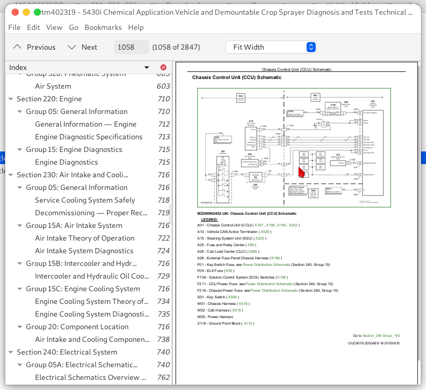
Chassis Control Unit (CCU) Theory of Operation...1057
Chassis Control Unit (CCU) Schematic...1058
Group 15T: Control Unit Power — ECU...743
Engine Control Unit (ECU) Theory Of Operation...1061
Engine Control Unit (ECU) Schematic...1063
Group 15U: Control Unit Power — SRC...743
Spray Rate Control Unit (SRC) Theory of Operation...1065
Spray Rate Control Unit (SRC) Schematic...1066
Group 15V: Control Unit Power — SSU...743
Steering System Control Unit (SSU) Theory of Operation...1069
Steering System Unit (SSU) Schematic...1070
Group 15W: Dome Light...743
Dome Light Theory of Operation...1072
Dome Light Schematic...1073
Group 15X: Electric Fuel Pump...1075
Electric Fuel Pump...1075
Electric Fuel Pump Schematic...1076
Group 15Y: Engine and Fuel Control...744
Engine and Fuel Control Theory of Operation...1080
Engine and Fuel Control Schematic...1082
Group 15Z: Engine Sensors...744
Engine Coolant Sensor Theory of Operation...1085
Engine Oil Pressure Sensor Theory of Operation...1087
Engine Speed Sensor Theory of Operation...1088
Engine Sensor Schematic...1089
Group 15AA: Fuel Level Sensor...744
Fuel Level Sensor Theory of Operation...1092
Fuel Level Sensor Schematic...1093
Group 15AB: GreenStar Display...744
GreenStar Display Theory of Operation...1095
GreenStar Display Schematic...1096
Group 15AC: GreenStar GPS Receiver...744
GPS Receiver Theory of Operation...1099
GPS Receiver Schematic...1100
Group 15AD: Horn...744
Horn Theory of Operation...1104
Horn Schematic...1105
Group 15AE: Hydraulic Oil Cooler Fan...744
Hydraulic Oil Cooler Fan Theory of Operation...1107
Hydraulic Oil Cooler Fan Schematic...1108
Group 15AF: Hydraulic Oil Temperature...744
Hydraulic Oil Temperature Theory of Operation...1111
Hydraulic Oil Temperature Schematic...1113
Group 15AG: Hydrostatic Boost...744
Hydrostatic Boost Theory of Operation...1116
Hydrostatic Boost Schematic...1117
Group 15AH: Ladder Electrical...744
Ladder Electrical Theory of Operation...1120
Ladder Electrical Schematic...1121
Group 15AI: Lights - Alert (Caution and Stop)...745
Alert Lights (Caution and Stop) Theory of Operation...1124
Alert Lights (Caution and Stop) Schematic...1125
Group 15AJ: Lights - Beacon...745
Beacon Lights Theory of Operation...1127
Beacon Lights Schematic...1128
Group 15AK: Lights - Delay (Egress)...745
Lights - Delay Theory Of Operation...1131
Lights - Delay Schematic...1132
Group 15AL: Lights - Field Lights...745
Field Lights 1 and 2 Theory of Operation...1135
Field Lights 1 and 2 Schematic...1136
Group 15AM: Lights - Park Lights...745
Park Lights Theory of Operation...1139
Park Lights Schematic...1140
Group 15AN: Lights - Road...745
Lights - Road Theory of Operation...1143
Lights - Road Schematic...1144
Group 15AO: Lights - Trailer...745
Trailer Lights Theory of Operation...1147
Trailer Lights Schematic...1148
Group 15AP: Lights - Warning and Turn Signal...745
Warning and Turn Signal Lights Theory of Operation...1152
Warning and Turn Signal Lights Schematic...1154
Group 15AQ: Multi-Function Lever...810
Multi-Function Lever Theory of Operation...1157
Multi-Function Lever Schematic...1159
Group 15AR: Multi-Function Lever Position...745
Multi-Function Lever Position Theory of Operation...1161
Multi-Function Lever Position Schematic...1162
Group 15AS: Operator Presence Switch...745
Operator Presence Switch Theory of Operation...1165
Operator Presence Switch Schematic...1166
Group 15AT: Park (Secondary) Brake...746
Secondary Brake Electrical Theory of Operation...1169
Secondary Brake Electrical Schematic...1171
Group 15AU: Power Supply...746
Electrical Power Theory of Operation...1179
Electrical Power Schematic...1185
Group 15AV: Power Mirror...746
Power Mirror Theory of Operation...1189
Power Mirror Schematic...1190
Group 15AW: Radio...746
Radio Theory of Operation...1193
Radio Schematic...1194
Group 15AX: Slip Control...746
Slip Control Theory of Operation...2178
Slip Control Schematic...1200
Group 15AY: Solution Control System...746
Solution Control System Theory of Operation...1210
Solution Control System Schematic...1219
Group 15AZ: Solution Pressure System...746
Solution Pressure Theory of Operation...1222
Solution Pressure Schematic...1223
Group 15BA: Solution Pump Oil Level...746
Solution Pump Oil Level Theory of Operation...1226
Solution Pump Oil Level Schematic...1227
Section 250: Power Train...2103
Group 05A: General Information...2103
Power Train General Information...2107
Power Train Operational Checkout...2108
Group 05B: Component Identification...2103
Power Train Component Identification...2115
Group 10: Test Procedures and Adjustments...2103
Hydrostatic System Test Specifications...2118
Hydrostatic Charge Pressure Test...2119
Adjust Hydrostatic Charge Pressure...2121
Hydrostatic Pump Servo Piston Pressure Test...2126
Hydrostatic Pump High Pressure Test...2129
Hydrostatic Pump Flow Test...2141
Front Hydrostatic Motor Case Drain Flow Test...2147
Rear Hydrostatic Motor Case Drain Flow Test...2149
Reverse Boost Engage Pressure Test...2151
Group 15A: Final Drive...2103
Final Drive Theory of Operation...2155
Group 15B: Hydrostatic Drive...2103
Hydrostatic Drive Theory of Operation...2162
Hydrostatic Drive Schematic...2167
Group 15C: Hydrostatic Pump Boost...2103
Hydrostatic Pump Boost Hydraulic Theory of Operation...2172
Hydrostatic Pump Boost Hydraulic Schematic...2175
Group 15D: Slip Control...2103
Slip Control Theory of Operation...2178
Slip Control Hydraulic Schematic...2179
Group 20: Power Train Components Location...2103
B05 — Charge Pressure Diagnostic Receptacle...2182
C23 — Front Hydrostatic Pump Servo Piston...2183
C24 — Rear Hydrostatic Pump Servo Piston...2184
D05 — Front Pump Reverse Circuit Make-Up Oil Piston...2185
D06 — Front Pump Forward Circuit Make-Up Oil Piston...2186
D07 — Rear Pump Reverse Circuit Make-Up Oil Piston...2187
D08 — Rear Pump Forward Circuit Make-Up Oil Piston...2188
F02 — Front Hydrostatic Charge Oil Filter...2189
F03 — Rear Hydrostatic Charge Oil Filter...2190
F04 — Front Hydrostatic Pump Suction Screen...2191
F05 — Rear Hydrostatic Pump Suction Screen...2192
G07 — Front Final Drive...2193
G08 — Rear Final Drive...2194
G09 — Slip Control Valve Block...2195
M05 — Left Front Wheel Motor...2196
M06 — Right Front Wheel Motor...2197
M07 — Left Rear Wheel Motor...2198
M08 — Right Rear Wheel Motor...2199
O8 — Left Rear Hydrostatic Motor Flush Orifice...2200
O9 — Right Rear Hydrostatic Motor Flush Orifice...2201
O10 — Hydrostatic Pump Equalizing Orifice...2202
O11 — Slip Control Orifice (plugged)...2203
O12 — Slip Control Left Front Wheel Motor Flow Restrictor...2204
O13 — Slip Control Right Front Wheel Motor Flow Restrictor...2205
P06 — Charge Pump, Front Hydrostatic Pump...2206
P07 — Front Hydrostatic Pump...2207
P08 — Charge Pump, Rear Hydrostatic Pump...2208
P09 — Rear Hydrostatic Pump...2209
V40 — Left Front Wheel Motor Directional Valve...2210
V41 — Right Front Wheel Motor Directional Valve...2211
V42 — Left Rear Wheel Motor Directional Valve...2212
V43 — Right Rear Wheel Motor Directional Valve...2213
V44 — Left Front Flush Relief Valve...2214
V45 — Right Front Flush Relief Valve...2215
V46 — Front Hydrostatic Pump Control Valve...2216
V47 — Front Hydrostatic Pump Charge Relief Valve...2217
V48 — Front Hydrostatic Pump Reverse Multi-Function Valve...2218
V49 — Front Hydrostatic Pump Forward Multi-Function Valve...2219
V50 — Rear Hydrostatic Pump Reverse Multi-Function Valve...2220
V51 — Rear Hydrostatic Pump Forward Multi-Function Valve...2221
V52 — Rear Hydrostatic Pump Charge Relief Valve...2222
V53 — Front Hydrostatic Pump Reverse Pressure Limiter Piston...2223
V54 — Front Hydrostatic Pump Reverse Pressure Relief Piston...2224
V55 — Front Hydrostatic Pump Forward Pressure Limiter Piston...2225
V56 — Front Hydrostatic Pump Forward Pressure Relief Piston...2226
V57 — Rear Hydrostatic Pump Reverse Pressure Limiter Piston...2227
V58 — Rear Hydrostatic Pump Reverse Pressure Relief Piston...2228
V59 — Rear Hydrostatic Pump Forward Pressure Limiter Piston...2229
V60 — Rear Hydrostatic Pump Forward Pressure Relief Piston...2230
V61 — Slip Control Bypass Spool...2231
Y01 — Left Front Wheel Motor Shift Solenoid Valve...2232
Y03 — Traction Control Valve...2233
Y04 — Left Rear Wheel Motor Shift Solenoid Valve...2234
Y14 — Right Front Wheel Motor Shift Solenoid Valve...2235
Y15 — Right Rear Wheel Motor Shift Solenoid Valve...2236
Section 260: Brakes...2237
Group 05A: General Information...2237
Steering and Brake Systems General Information...2239
Brake System Component Identification...2240
Group 05B: Component Identification...2237
Brake Component Identification...2242
Group 10: Tests...2237
Brake Test Specifications...2244
Park Brake Release Pressure Test...2245
Service Brake Pressure Test...2247
Bleeding Service Brakes...2249
Group 15A: Secondary Brake...2237
Secondary Brake Theory of Operation...2251
Secondary Brake Schematic...2252
Group 15B: Service Brake...2237
Service Brake Theory of Operation...2255
Service Brake Schematic...2256
Group 15C: Trailer Brake...2237
Trailer Brake Theory of Operation...2259
Trailer Brake Schematic...2260
Section 270: Hydraulic System...2262
Group 05A: General Information...2262
Hydraulic System General Information...2269
Group 05B: Component Identification...2262
Hydraulic Component Identification...2274
Group 10: Test Procedures...2262
Hydraulic System Specifications...2279
Hydraulic Pump Pressure Test and Adjustment...2280
Hydraulic Load Sense Pressure Test...2282
Hydraulic Pump Flow Test...2284
Diaphragm Pump Proportional Valve Hydraulic Flow Test...2286
Quick Fill Pump Proportional Valve Hydraulic Flow Test...2289
Group 15A: Basic Hydraulic System...2262
Basic Hydraulic System Theory of Operation...2294
Basic Hydraulic System Schematic...2296
Group 15B: Boom Fold Hydraulic System...2262
Boom Fold Hydraulic Theory of Operation...2300
Boom Fold Hydraulic Schematic — 24/12 M, 27/15 M, 28/15 M, 30/15 M, 32/18 M, 33/18 M, 36/18 M...2301
Boom Fold Hydraulic Schematic — 36/24/18 M...2304
Group 15C: Boom Raise Hydraulic System...2262
Boom Raise Hydraulic Theory of Operation...2308
Boom Raise Hydraulic Schematic...2309
Group 15D: Boom Tilt Hydraulic System...2262
Boom Tilt Hydraulic Theory of Operation...2312
Boom Tilt Hydraulic Schematic...2313
Group 15E: Boom Variable Geometry Hydraulic System...2262
Variable Geometry Hydraulic Theory of Operation...2316
Variable Geometry Hydraulic Schematic...2317
Group 15F: Diaphragm Solution Pump Hydraulic System...2262
Diaphragm Solution Pump Motor Hydraulic Theory of Operation...2320
Diaphragm Solution Pump Motor Hydraulic Schematic...2321
Group 15G: Ladder Hydraulic System...2262
Ladder Hydraulic Theory of Operation...2324
Ladder Hydraulic Schematic...2325
Group 15H: Pressure Washer Hydraulic...2263
Pressure Washer Hydraulic Theory of Operation...2327
Pressure Washer Hydraulic Schematic...2328
Group 15I: Quick Fill Pump Motor Hydraulic System...2263
Quick Fill Pump Motor Hydraulic Theory of Operation...2330
Quick Fill Pump Motor Hydraulic Schematic...2331
Group 20: Hydraulic Components Location...2263
AutoTrac Steering Valve Port Location...2334
Combination Valve Port Location...2335
Four-Wheel Steering Valve Port Location...2339
A01 — Hydraulic Attenuator...2341
A02 — Boom Accumulator...2342
B01 — Four-Wheel Steer Valve Diagnostic Receptacle...2343
B02 — Load Sense Diagnostic Receptacle...2344
B03 — Hydraulic Pump Pressure Diagnostic Receptacle...2345
C01 — Front Left Steering Cylinder...2346
C02 — Front Right Steering Cylinder...2347
C03 — Rear Left Steering Cylinder...2348
C04 — Rear Right Steering Cylinder...2349
C05 — Left Front Tread Adjust Cylinder...2350
C06 — Right Front Tread Adjust Cylinder...2351
C07 — Left Rear Tread Adjust Cylinder...2352
C08 — Right Rear Tread Adjust Cylinder...2353
C09 — Pendulum Lock Cylinder...2354
C10 — Boom Tilt Cylinder...2355
C11 — Left Variable Geometry Cylinder...2356
C12 — Right Variable Geometry Cylinder...2357
C13 — Left Inner Fold Cylinder...2358
C14 — Right Inner Fold Cylinder...2359
C15 — Left Outer Fold Cylinder...2360
C16 — Right Outer Fold Cylinder...2361
C17 — Boom Lift Cylinders...2362
C18 — Left Service Brake Calipers...2363
C19 — Ladder Cylinder...2364
C20 — Left Park Brake...2365
C21 — Right Service Brake Calipers...2366
C22 — Right Park Brake...2367
C25 — Left Outer 2 Fold Cylinder...2368
C26 — Right Outer 2 Fold Cylinder...2369
D09 — Pendulum Lock Check Valve...2370
D10 — Left Outer Fold Check Valve...2371
D11 — Left Inner Fold Check Valve...2372
D12 — Left Variable Geometry Up Check Valve...2373
D13 — Right Variable Geometry Up Check Valve...2374
D14 — Right Inner Fold Check Valve...2375
D15 — Right Outer Unfold Check Valve...2376
D16 — Tilt Right Check Valve...2377
D17 — Boom Lower Check Valve...2378
D18 — Tilt Left Check Valve...2379
D19 — Right Outer Fold Check Valve...2380
D20 — Right Inner Unfold Check Valve...2381
D21 — Right Variable Geometry Down Check Valve...2382
D22 — Left Variable Geometry Down Check Valve...2383
D23 — Left Inner Unfold Check Valve...2384
D24 — Left Outer Unfold Check Valve...2385
D25 — Pendulum Float Check Valve...2386
D26 — Outer 2 (24 M) Unfold Check Valve...2387
D27 — Outer 2 (24 M) Fold Check Valve...2388
D28 — Left Front Tread IN Check Valve...2389
D29 — Left Front Tread OUT Check Valve...2390
D30 — Right Front Tread IN Check Valve...2391
D31 — Right Front Tread OUT Check Valve...2392
D32 — Left Rear Tread IN Check Valve...2393
D33 — Left Rear Tread OUT Check Valve...2394
D34 — Right Rear Tread IN Check Valve...2395
D35 — Right Rear Tread OUT Check Valve...2396
F01 — Hydraulic System Filter...2397
F06 — Hydraulic Pump Suction Screen...2398
G01 — Combination Valve Block with Quick Fill...2399
G02 — Combination Valve Block without Quick Fill...2400
G03 — Pneumatic System...2401
G04 — Tread Adjust Valve Block...2402
G05 — AutoTrac Valve Block...2403
G06 — Four-Wheel Steer Valve Block...2404
G10 — Boom Hydraulic Valve Block...2405
H01 — Auxiliary Hydraulic Oil Cooler...2406
H02 — Hydraulic Oil Heat Exchanger...2407
M01 — Hydraulic Motor, Quick Fill Pump...2408
M03 — Hydraulic Motor, Solution Pump...2409
M04 — Hydraulic Motor, Pressure Washer (Optional)...2410
O1 — Boom Lift Orifice...2411
O2 — Boom Lower Orifice...2412
O3 — Left Outer Fold Cylinder Orifice...2413
O4 — Left Inner Fold Cylinder Orifice...2414
O5 — Tilt Cylinder Orifice...2415
O6 — Pendulum Lock Cylinder Orifice...2416
O7 — Combination Valve Load Sense Orifice...2417
O14 — Left Outer Unfold Cylinder Orifice...2418
O15 — Right Inner Fold Cylinder Orifice...2419
O16 — Right Outer Unfold Cylinder Orifice...2420
O17 — Right Outer Fold Cylinder Orifice...2421
O18 — Left Outer 2 Fold Cylinder Orifice...2422
O19 — Left Outer 2 Unfold Cylinder Orifice...2423
O20 — Right Outer 2 Unfold Cylinder Orifice...2424
O21 — Right Outer 2 Fold Cylinder Orifice...2425
O22 — Left Variable Geometry Up Orifice...2426
O23 — Left Variable Geometry Down Orifice...2427
O24 — Right Variable Geometry Up Orifice...2428
O25 — Right Variable Geometry Down Orifice...2429
O26 — Left Front Tread Adjust Orifice...2430
O27 — Right Front Tread Adjust Orifice...2431
O28 — Left Rear Tread Adjust Orifice...2432
O29 — Right Rear Tread Adjust Orifice...2433
P01 — Auxiliary Hydraulic Pump...2434
P05 — Secondary Steering Pump...2435
R01 — Hydraulic Reservoir...2436
V01 — Priority Valve...2437
V02 — Manual Steering Valve...2438
V03 — AutoTrac Proportional Steering Valve...2439
V04 — Right Outer Fold Cylinder Valve...2440
V05 — Left Outer Fold Cylinder Valve...2441
V06 — Trailer Brake Valve...2442
V08 — Shuttle Valve, Load Sense...2443
V09 — Pressure Washer Valve (Optional)...2444
V10 — Right Inner Fold Cylinder Valve...2445
V11 — Left Inner Fold Cylinder Valve...2446
V12 — Ladder Valve...2447
V13 — Shuttle Valve, AutoTrac...2448
V14 — Shuttle Valve, Trailer Brakes...2449
V15 — Reverse Boost Valve...2450
V16 — Load Sense Jam Valve...2451
V17 — Solution Pump Compensator Valve...2452
V18 — Solution Pump Proportional Valve...2453
V19 — Auxiliary Fill Compensator Valve...2454
V20 — Auxiliary Fill Proportional Valve...2455
V21 — Park Brake Proportional Valve...2456
V22 — Service Brake Valve...2457
V23 — Pendulum Lock Cylinder Valve...2458
V24 — Pendulum Lock Hold Cylinder Valve...2459
V25 — Tilt Cylinder Valve...2460
V26 — Left Variable Geometry Cylinder Valve...2461
V27 — Right Variable Geometry Cylinder Valve...2462
V28 — Boom Lift Valve...2463
V30 — Boom Lower Valve...2464
V31 — Right Front Steering Cylinder Toe Control Valve...2465
V32 — Trailer Park Brake Proportional Valve...2466
V33 — Trailer Service Brake Proportional Valve...2467
V34 — AutoTrac Relief Valve...2468
V35 — AutoTrac Relief Valve...2469
V36 — Left Front Steering Cylinder Toe Control Valve...2470
V37 — Four-Wheel Steer Relief Valve...2471
V38 — Four-Wheel Steer Proportional Valve...2472
V39 — Oil Cooler Bypass Valve...2473
V62 — Left Rear Toe Control Valve...2474
V63 — Right Rear Toe Control Valve...2475
V64 — Outer 2 (24 M) Fold Valve...2476
V65 — Left Front Tread Adjust Valve...2477
V66 — Right Front Tread Adjust Valve...2478
V67 — Left Rear Tread Adjust Valve...2479
V68 — Right Rear Tread Adjust Valve...2480
X01 — Trailer Brake Supply (Red Line)...2481
X02 — Trailer Brake Sense (Yellow Line)...2482
Group 50: Diagnostic Tests and Adjustments...2267
Hydrostatic System...2501
Section 275: Tread Adjust System...2519
Group 05A: General Information...2519
Tread Adjust Hydraulic System General Information...2521
Group 05B: Component Identification...2519
Tread Adjust Hydraulic Component Identification...2524
Group 15: Hydraulic Tread Adjust...2519
Tread Adjust Hydraulic Theory of Operation...2528
Tread Adjust Hydraulic Schematic...2530
Group 20: Component Location...2519
Tread Adjust Component Location...2533
Section 280: Steering System...2534
Group 05A: General Information...2534
Steering System General Information...2536
Group 05B: Component Identification...2534
Steering Component Identification...2538
Group 15A: Steering Hydraulic System...2534
Steering Hydraulic Theory of Operation...2543
Steering Hydraulic Schematic...2547
Group 15B: Secondary Steering System...2534
Secondary Steering Hydraulic Theory of Operation...2550
Secondary Steering Hydraulic Schematic...2551
Group 20: Component Location...2534
Steering Component Location...2554
Section 290: Operator's Cab...2555
Group 10: Operational Checks...2555
Air-Conditioning System Heater and Seat - Summary of References...2558
Air Conditioning System and Heater - Test Sequence...2559
Air Comfort Seat - Test Sequence...2565
Group 15: Tests and Adjustments...2555
Operator's Cab - Tests and Adjustments - Summary of References...2568
Air Conditioning — Special Tools...2569
Air Conditioning System - Specifications...2570
Air Conditioning System - Safety at Work...2571
Air-Conditioning System - Storage of Refrigerant Containers...2573
Air Conditioning - Important...2574
Service Work on Air Conditioning System...2575
Air Conditioning System - Preventive Maintenance...2578
Fill with Refrigerant Oil...2579
Air Conditioning - Test with Air Conditioning Service Unit...2581
Air Conditioning - System Test...2582
Air Conditioning System - Pressure Deviations...2594
Group 20A: Heating and Ventilation...2555
Heating and Ventilation — Summary of References...2597
Heating and Ventilation — Temperature Control — Theory of Operation...2598
Heating and Ventilation — Theory of Operation...2599
Group 20B: Air Conditioning System...2555
Air Conditioning System — Summary of References...2602
Air Conditioning System — R134a Refrigerant...2603
Air Conditioning System — Principle of Heat Exchange...2604
Air Conditioning System — Theory of Operation...2605
Air Conditioning System — Refrigerant Circuit Layout...2607
Air Conditioning System — Compressor, Component Information...2609
Air Conditioning System — Condenser, Component Information...2610
Air Conditioning System — Receiver-Drier, Component Information...2611
Air Conditioning System — Expansion Valve, Component Information...2612
Air Conditioning System — Thermostat Switch, Component Information...2614
Air Conditioning System — Evaporator, Component Information...2615
Air Conditioning System — High/Low Pressure Switch, Component Information...2616
Air Conditioning System — Temperature Control...2617
Section 300: Solution System...2618
Group 05: General Information...2618
Solution System Component Identification...2623
Group 15A: Solution System — Overall Description...2618
Solution System Theory of Operation...2631
Solution System Schematics...2637
Group 15B: Solution System — Spraying...2618
Solution Spray Theory of Operation...2649
Solution Spray Schematic...2655
Group 15C: Solution System — Agitation...2618
Solution Agitation Theory of Operation...2660
Solution Agitation Schematic...2661
Group 15D: Solution System — Rinse...2618
Solution Rinse Theory of Operation...2664
Solution Rinse Schematic...2665
Group 15E: Solution System — Eductor...2618
Solution Eductor Theory of Operation...2670
Solution Eductor Schematic...2673
Group 15F: Solution System — Load with Diaphragm Pump...2618
Solution Load with Diaphragm Pump Theory of Operation...2676
Solution Load with Diaphragm Pump Schematic...2677
Group 15G: Solution System — Load with Quick Fill Pump...2618
Solution Load with Quick Fill Pump Theory of Operation...2682
Solution Load with Quick Fill Pump Schematic...2685
Group 20: Component Location...2618
D100 — Rinse Tank Check Valve...2689
D101 — Eductor Rinse Check Valve...2690
D102 — Closed Chemical Transfer Connection...2691
D103 — Closed Chemical Transfer Rinse Connection...2692
D104 — Solution Tank Fill Check Valve...2693
D105 — Quick Fill Check Valve...2694
F100 — Suction Screen...2695
F101 — Pressure Screen...2696
F102 — Quick Fill Screen...2697
O100 — Eductor Venturi...2698
P100 — Solution Pump 1...2699
P101 — Solution Pump 2...2700
P102 — Quick Fill Pump...2701
P103 — Pressure Washer Pump...2702
R100 — Solution Tank...2703
R101 — Rinse Tank...2704
R102 — Eductor Tank...2705
R104 — Clean Wash Water Tank...2706
V100 — Tank Sump 1 Valve...2707
V101 — Tank Sump 2 Valve...2708
V102 — Rinse Tank Fill Valve...2709
V103 — Rinse Tank Valve...2710
V104 — Solution Tank Fill Valve...2711
V105 — Agitation/Tank Rinse Valve...2712
V106 — Eductor/Eductor Rinse Valve...2713
V107 — Tank/Pump Valve...2714
V108 — Bypass Valve...2715
V109 — Spray Rate Regulator Valve...2716
V110 — Transfer Valve...2717
V111 — Eductor Tank Sump Valve...2718
V112 — Eductor Jug Valve...2719
V113 — Eductor Flush Valve...2720
V114 — Hand Nozzle Valve...2721
V115 — Pressure Regulator Valve...2722
V116 — Pressure Relief Valve 1...2723
V117 — Pressure Relief Valve 2...2724
V118 — Pressure Recirculation Valve...2725
V121 — D Spray Valve...2726
V122 — AK Spray Valve...2727
V123 — C Spray Valve...2728
V124 — B Spray Valve...2729
V125 — A Spray Valve...2730
V126 — AJ Spray Valve...2731
V127 — Left Off-Center Spray Valve...2732
V131 — AE Spray Valve...2733
V132 — AF Spray Valve...2734
V133 — E Spray Valve...2735
V134 — H Spray Valve...2736
V135 — J Spray Valve...2737
V136 — AG Spray Valve...2738
V137 — Right Off-Center Spray Valve...2739
Y61 — D Spray Valve Solenoid...2740
Y62 — AK Spray Valve Solenoid...2741
Y63 — C Spray Valve Solenoid...2742
Y64 — B Spray Valve Solenoid...2743
Y65 — A Spray Valve Solenoid...2744
Y66 — AJ Spray Valve Solenoid...2745
Y67 — Left Edge Inner Valve Solenoid...2746
Y68 — Left Edge Outer Valve Solenoid...2747
Y71 — AE Spray Valve Solenoid...2748
Y72 — AF Spray Valve Solenoid...2749
Y73 — E Spray Valve Solenoid...2750
Y74 — H Spray Valve Solenoid...2751
Y75 — J Spray Valve Solenoid...2752
Y76 — AG Spray Valve Solenoid...2753
Y77 — Right Edge Inner Valve Solenoid...2754
Y78 — Right Edge Outer Valve Solenoid...2755
Section 320: Pneumatic System...2756
Group 05: General Information...2756
Air Suspension System General Information...2758
Group 15A: Air System...2756
Basic Air System...2760
Group 15B: Air Suspension Diagnostics...621
Air Suspension Theory of Operation...2763
Air Suspension Schematic...2765
Group 15C: Boom Air Controls...2756
Spray Valve Solenoids...2768
Group 20: Air Suspension Component Location...2756
C101 — Left Front Air Bag...2770
C102 — Right Front Air Bag...2771
C103 — Left Rear Air Bag...2772
C104 — Right Rear Air Bag...2773
F104 — Air Dryer – Regulator...2774
P104 — Air Compressor...2776
R103 — Air Reservoir...2777
V140 — Left Front Air Suspension Valve...2778
V141 — Right Front Air Suspension Valve...2779
V142 — Left Rear Air Suspension Valve...2780
V143 — Right Rear Air Suspension Valve...2781
V144 — Unload Valve...2782
V145 — Priority Valve...2783
Section 399: Service Tools...2784
Group 10: Service Tools and Kits...2784
38H1029 — Tee (-4 ORFS)...2787
38H1030 — Tee (-6 ORFS)...2788
38H1098 — 90° Elbow (-16 ORFS Sw)...2789
38H1145 — Plug ( -4 ORFS)...2790
38H1146 — Plug ( -6 ORFS)...2791
38H1147 — Plug ( -8 ORFS)...2792
38H1148 — Plug ( -10 ORFS)...2793
38H1149 — Plug ( -12 ORFS)...2794
38H1150 — Plug ( -16 ORFS)...2795
38H1172 — Adapter ( -6 to -10 ORFS)...2796
38H1414 — Cap ( -4 ORFS)...2797
38H1415 — Cap ( -6 ORFS)...2798
38H1416 — Cap (-8 ORFS)...2799
38H1417 — Cap ( -10 ORFS)...2800
38H1418 — Cap ( -12 ORFS)...2801
38H1419 — Cap ( -16 ORFS)...2802
38H1427 — Straight Fitting (-10 (m) ORB x -16 (m) ORFS)...2803
38H1482 — Reducer (-12 (Sw) ORFS x -10 (m) ORFS)...2804
38H1597 — 90° Elbow (-10 (m) ORB x -10 (Sw) ORFS)...2805
38H1611 — Reducer (-12 (Sw) ORFS x -08 (m) ORFS)...2806
FKM10409 — Battery Load Tester...2807
FKM10444 — Leak detector...2808
FKM10470 — Pressure Measuring System (stage 1)...2809
FKM10471 — Pressure measuring system (stage 2)...2810
FKM10472-4 — Temperature sensor...2811
FKM10474 — Fill and Check Device...2812
JDG820 — Flywheel Turning Tool...2813
JDG10974EU — Air Conditioning Service Unit...2814
JT02156A — Digital Pressure and Temperature Analyzer...2815
JT02158 — Digital Pressure and Temperature Analyzer...2816
JT02159 — 20 ft Cable...2817
JT02160 — 10,000 PSI Transducer...2818
JT02161 — 3500 kPa (350 bar) (500 psi) Transducer...2819
JT02162 — 5000 PSI Transducer...2820
JT05495 — Adapter Fitting...2821
JT05709 — Reflective Tape...2822
JT05719 — Hand Held Digital Tachometer...2823
JT05791A — Multimeter...2824
JT07148 — Digital Hydraulic Flow Tester...2825
JT07253 — Infrared Temperature Gun...2826
KJD10529 — Cutting Tool...2827
KJD10530 — Pliers...2828
KJD10570 — Safety Equipment (Air Conditioning Service)...2829
KJD10571 — Protective Cover for Air Conditioning Service Unit...2830
KJD10572 — Standard Flushing Kit (Air Conditioning Service)...2831
KJD10573 — UV Contrast Agent (Air Conditioning Service)...2832
KJD10574 — Hose Extensions (2.5 m) (Air Conditioning Service)...2833
KJD10575 — PAG Oil (Air Conditioning Service)...2834
KJD10576UV — Lamp and Safety Goggles (Air Conditioning Service)...2835
KJD10577 — Filter/Receiver-Drier Cartridge for Air Conditioning Service Unit...2836
X3JC82-12-12 — Hose Fitting (-12 F ORFS x 3/4 in. (19.05 mm) M Hose Barb)...2837
XPD34BTX — Diagnostic Receptacle ( -4, 37° Flare)...2838
XPD34BTL — Diagnostic Receptacle ( -4 ORFS)...2839
XPD36BTL — Diagnostic Receptacle ( -6 ORFS)...2840
John Deere Demountable Self-Propelled Crop Sprayers 5430i Diagnosis and Tests Service Manual (TM402319)
![]()