
John Deere Residential Mowers Z625, Z645, Z655, and Z665 EZtrak Diagnostic and Repair Technical Manual (TM113119)
Complete service manual with electrical wiring diagrams for John Deere Residential Mowers Z625, Z645, Z655, and Z665 EZtrak, with workshop information to maintain, diagnose repair, and service like professional mechanics.
John Deere Residential Mowers Z625, Z645, Z655, and Z665 EZtrak workshop service & repair manual includes:
* Numbered table of contents easy to use so that you can find the information you need fast.
* Detailed sub-steps expand on repair procedure information
* Numbered instructions guide you through every repair procedure step by step.
* Troubleshooting and electrical service procedures are combined with detailed wiring diagrams for ease of use.
* Notes, cautions and warnings throughout each chapter pinpoint critical information.
* Bold figure number help you quickly match illustrations with instructions.
* Detailed illustrations, drawings and photos guide you through every procedure.
* Enlarged inset helps you identify and examine parts in detail.
TM113119 - John Deere Residential Mowers Z625, Z645, Z655, and Z665 EZtrak Technical Manual (Diagnostics and Repair).PDF
TM113119 - John Deere Residential Mowers Z625, Z645, Z655, and Z665 EZtrak Technical Manual (Diagnostics and Repair).EPUB
Total Pages: 965 pages
File Format: PDF (bookmarked, ToC, Searchable, Printable, high quality) & EPUB/MOBI/AZW for Kindle/iPad/iPhone/Android.
Language: English
MAIN SECTIONS
Foreword
General Information
Safety
General Specifications
Fuel and Lubricants
Machine Specifications
Engine Repair B&S
Repair Engine Twin Cylinder
Engine Repair Kawasaki
Engine Repair
Starting Motor Repair
Electrical Repair
Component Location
Wiring Harness
Power Train Repair
Component Location (S.N. -130000)
Component Location (S.N. 130001- )
Repair (S.N. -130000)
Repair (S.N. 130001- )
Attachments Repair
Component Location
Repair
Miscellaneous Repair
Component Location
Repair
Engine Diagnosis, Tests, and Adjustments B&S
Diagnosis
Tests and Adjustments
Engine Diagnosis, Tests, and Adjustments Kawasaki
Component Location
General Information
Theory of Operation
Diagnosis
Tests and Adjustments
Electrical Diagnosis, Tests, and Adjustments
Theory of Operation
Diagnosis
Tests and Adjustments
Wiring Schematics
Connector Information
Power Train Diagnosis, Tests, and Adjustments
Theory of Operation (S.N. -130000)
Theory of Operation (S.N. 130001- )
Diagnosis (S.N. -130000)
Diagnosis (S.N. 130001- )
Tests and Adjustments (S.N. -130000)
Tests and Adjustments (S.N. 130001- )
Attachments Diagnosis, Tests, and Adjustments
Diagnosis
Tests and Adjustments
Miscellaneous Tests and Adjustments
Tests and Adjustments
Service Tools and Kits
Service Tools
tm113119 - Z625, Z645, Z655, and Z665 EZtrak™ Mower
Table of Contents
Foreword
Section 10: General Information
Group 05: Safety
Recognize Safety Information
Understand Signal Words
Follow Safety Instructions
Practice Safe Maintenance
Use Proper Tools
Handle Fluids Safely—Avoid Fires
Drain Gasoline When Storing Machine
Prevent Acid Burns
Prevent Battery Explosions
Handling Batteries Safely
Prepare for Emergencies
Park Machine Safely
Support Machine Properly
Wear Protective Clothing
Work in Clean Area
Service Machines Safely
Work In Ventilated Area
Illuminate Work Area Safely
Replace Safety Signs
Use Proper Lifting Equipment
Service Tires Safely
Decommissioning — Proper Recycling and Disposal of Fluids and Components
Protect Against High Pressure Spray
Live With Safety
Group 10: General Specifications
Service Recommendations for O-Ring Boss Fittings
Service Recommendations For Flat Face O-Ring Seal Fittings
Metric Cap Screw Torque Values—Grade 7
Metric Bolt and Screw Torque Values
Unified Inch Bolt and Screw Torque Values
Group 15: Fuel and Lubricants
Gasoline Engine Oil
Oil Filters
Gasoline Fuel for 4-Cycle Engines
Transmission and Hydraulic Oil
Grease
Mixing of Lubricants
Alternative and Synthetic Lubricants
Lubricant Storage
Gasoline and Engine Storage
Carburetor Cleaning
Carburetor Cleaning Methods
Group 20: Machine Specifications
Machine Specifications (S.N. -130000)
Machine Specifications (S.N. 130001-150000 )
Machine Specifications (S.N. 150001-170000)
Machine Specifications (S.N. 170001- )
Product Identification Number Location
Section 20: Engine Repair B&S
Group 10: Repair Engine Twin Cylinder
Summary of References
Essential or Recommended Tools
Service Equipment and Tools
Specifications
Remove and Install Blower Housing
Remove and Install Air Cleaner
Remove Two Barrel Carburetor
Install Two Barrel Carburetor
Repair Two Barrel Carburetor
Assemble Two Barrel Carburetor
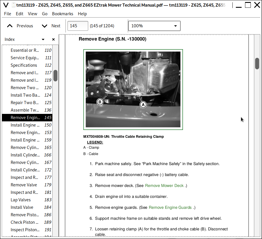
Remove Engine (S.N. -130000)
Install Engine (S.N. -130000)
Remove Engine (S.N. 130001-)
Install Engine (S.N. 130001-)
Remove Cylinder Air Guides
Install Cylinder Air Guides
Remove Cylinder Head
Install Cylinder Head
Inspect and Repair Cylinder Head
Remove Valve
Inspect and Repair Valve
Lap Valves
Install Valve
Remove Piston, Rings and Rod
Check Piston Ring End Gap
Inspect Piston and Rod
Assemble Piston and Rod
Install Piston and Rod
Inspect Cylinder Bore
Hone Cylinder Bore
Clean Cylinder Bore
Resize Cylinder Bore
Remove Flywheel
Install Flywheel
Remove and Install Stator
Remove and Inspect Crankshaft and Camshaft
Crankshaft and Camshaft Component Location
Install Crankshaft and Camshaft
Inspect Magneto Bearing
Inspect PTO and Cam Bearing
Service Breather Valve
Remove Oil Pump
Install Oil Pump
Inertia Starting Motor Components
Remove and Install Starting Motor
Disassemble Inertia Starting Motor
Assemble Inertia Starting Motor
Replace Inertia Pinion Gear
Section 25: Engine Repair Kawasaki
Group 10: Engine Repair
Summary of References
Specifications
Replace Fuel Filter, FS730V
Remove and Install Fuel Pump, FS730V
Remove and Install Muffler, FS730V
Remove Engine, FS730V
Install Engine, FS730V
Remove and Install Carburetor, FS730V
Disassemble and Assemble Carburetor, FS730V
Remove and Install Intake Manifold, FS730V
Remove and Install Crankcase Breather, FS730V
Remove and Install Blower Housing, FS730V
Remove and Install Ignition Coil, FS730V
Remove and Install Flywheel, FS730V
Remove and Install Stator, FS730V
Remove and Install Rocker Arm Cover, FS730V
Remove and Install Rocker Arm and Push Rod, FS730V
Inspect Rocker Arm and Push Rod, FS730V
Remove Cylinder Head, FS730V
Disassemble and Assemble Cylinder Head, FS730V
Install Cylinder Head, FS730V
Inspect Cylinder Head and Valves, FS730V
Analyze Valves, FS730V
Recondition Valve Seats, FS730V
Lap Valve, FS730V
Remove and Install Crankcase Cover, FS730V
Crankcase Cover Disassemble, Inspect, and Assemble, FS730V
Disassemble and Assemble Governor, FS730V
Remove and Install Camshaft and Tappets, FS730V
Inspect Camshaft and Tappets, FS730V
Remove Piston and Connecting Rod, FS730V
Disassemble Piston and Connecting Rod, FS730V
Inspect Piston and Connecting Rod, FS730V
Check Piston Ring End Gap, FS730V
Assemble and Install Piston and Connecting Rod, FS730V
Analyze Piston Ring Wear, FS730V
Analyze Piston Wear, FS730V
Remove and Install Crankshaft, FS730V
Crankshaft Inspection, FS730V
Check Connecting Rod-to-Crankshaft Clearance, FS730V
Inspect Crankshaft and Connecting Rod Wear, FS730V
Replace Oil Seal, FS730V
Deglaze Cylinder Bore, FS730V
Resize Cylinder Bore, FS730V
Group 20: Starting Motor Repair
Summary of References
Remove and Install Starting Motor
Disassemble and Assemble Starting Motor
Inspect Starting Motor
Section 30: Electrical Repair
Group 10: Component Location
Electrical Component Location
Group 20: Wiring Harness
Summary of References
Wiring Harness Legend (S.N. -120000)
W1 Main Wiring Harness (S.N. -120000)
W1 Main Wiring Harness Color Codes (S.N. -120000)
Wiring Harness Legend (S.N. 120001- )
W1 Main Wiring Harness (S.N. 120001-150000)
W1 Main Wiring Harness Color Codes (S.N. 120001-150000)
W1 Main Wiring Harness (S.N. 150001- )
W1 Main Wiring Harness Color Codes (S.N. 150001- )
W2 Engine Wiring Harness
W3 Lighting Kit Wiring Harness
Section 40: Power Train Repair
Group 10: Component Location (S.N. -130000)
Summary of References
Control Linkage Components (S.N. -130000)
Hydraulic System Components (S.N. -130000)
Hydrostatic Pump Components (S.N. -130000)
Hydrostatic Pump Components Legend (S.N. -130000)
Hydraulic Reservoir Components (S.N. -130000)
Group 15: Component Location (S.N. 130001- )
Summary of References
Control Linkage Components (S.N. 130001- )
Transmission Serviceable Components (S.N. 130001- )
Group 20: Repair (S.N. -130000)
Summary of References
Other Material
Specifications
Replace Transmission Drive Belt (S.N. -130000)
Change Hydraulic Oil and Filter (S.N. -130000)
Remove and Install Wheel Motor (S.N. -130000)
Remove Hydrostatic Pump (S.N. -130000)
Install Hydrostatic Pump (S.N. -130000)
Disassemble Hydrostatic Pump (S.N. -130000)
Assemble Hydrostatic Pump (S.N. -130000)
Group 25: Repair (S.N. 130001- )
Summary of References
Other Material
Drain and Replace Transaxle Oil (S.N. 130001- )
Remove and Install Transaxle (S.N. 130001- )
Remove and Install Traction Drive Belt (S.N. 130001- )
Replace Input Shaft Seal (S.N. 130001- )
Replace Bypass Seal (S.N. 130001- )
Replace Axle Seal (S.N. 130001- )
Replace Control Shaft Seal (S.N. 130001- )
Replace Brake Lever Seal (S.N. 130001- )
Remove and Install Transaxle Case Plug (S.N. 130001- )
Section 50: Attachments Repair
Group 10: Component Location
Summary of References
Deck and Lift Assembly
Deck Lift Control and Linkage
Deck 48HC Legend
Deck 48HC
Deck Shields—48HC Deck
Deck 54HC Legend
Deck 54HC
Deck Shields—54HC
Deck 60HC Legend
Deck 60HC
Deck Shields—60HC Deck
Spindle Section
Group 20: Repair
Summary of References
Specifications
Remove Mower Blades
Install Mower Blades
Remove Mower Deck
Install Mower Deck
Replace Mower Drive Belt (48HC and 54HC)
Replace Mower Drive Belt (60HC)
Remove and Install Deck Lift Assist Spring
Sharpen Mower Blades
Balance Mower Blades
Disassemble Mower Deck Spindle
Assemble Mower Deck Spindle
Repair Mower Deck Idlers
Section 60: Miscellaneous Repair
Group 10: Component Location
Summary of References
Park Brake Components (S.N. -130000)
Park Brake Components (S.N. 130001- )
Seat and Pan Components
Fuel Tank and Line Components (S.N. -130000)
Fuel Tank and Line Components (S.N. 130001- )
Muffler and Heat Shield—Z645, Z655 (S.N. -120000)
Muffler and Heat Shield—Z645, Z655 (S.N. 120001- )
Muffler and Heat Shield—Z665 (S.N. -150000)
Muffler and Heat Shield—Z665 (S.N. 150001-)
Group 20: Repair
Summary of References
Specifications
Remove Engine Guards
Remove and Install Control Console
Remove and Install Seat
Remove and Install Seat Platform
Remove and Install Control Panel
Remove and Install Foot Plate
Front Caster Wheels
Repair Park Brake (S.N. 130001- )
Section 220: Engine Diagnosis, Tests, and Adjustments B&S
Group 10: Diagnosis
B&S V-Twin, Diagnose Engine Starting
B&S V-Twin, Diagnose Carburetor, Air and Fuel
B&S V-Twin, Engine Will Not Crank
B&S V-Twin, Engine Cranks But Will Not Start
B&S V-Twin, Engine Runs Erratically
B&S V-Twin, Engine Runs Then Dies
B&S V-Twin, Engine Backfires or Misses
B&S V-Twin, Engine Overheats
B&S V-Twin, Engine Has Loss of Power
Group 20: Tests and Adjustments
Summary of References
Specifications
Service Equipment and Tools
Adjust Throttle and Choke Cable, V-Twin
Adjust Governor - Static, V-Twin
Adjust Governor - Dynamic, V-Twin
Test Crankcase Vacuum, V-Twin
Test Cylinder Leakdown, V-Twin
Test Cylinder Balance, V-Twin
Adjust Armature Air Gap, V-Twin
Adjust Valve Clearance, V-Twin
Test Engine Oil Pressure, V-Twin
Section 225: Engine Diagnosis, Tests, and Adjustments Kawasaki
Group 10: Component Location
Engine Block
Valves and Governor
Intake and Carburetor Components
Group 20: General Information
Cleaning Carburetors
Cleaning Methods
Fuel
Group 30: Theory of Operation
Engine Oil Flow Chart
Lubrication System Operation
Governor Operation
Crankcase Breather Operation
Automatic Compression Release (ACR) Operation
Cooling System Operation
Ignition System Operation
Carburetor Operation
Group 40: Diagnosis
Kawasaki, Diagnose Carburetor Air and Fuel
Kawasaki, Diagnose Carburetor
Kawasaki, Diagnose Starting
Kawasaki, Diagnose Starting Motor
Group 50: Tests and Adjustments
Summary of References
Specifications
Check and Adjust Choke, FS730V
Check and Adjust Throttle Cable, FS730V
Adjust Governor Static, FS730V
Adjust Low Idle, FS730V
Adjust High Idle, FS730V
Cylinder Compression Test, FS730V
Cylinder Leak-Down Test, FS730V
Check and Adjust Valve Clearance, FS730V
Fan Screen Check and Adjust, FS730V
Ignition Coil Air Gap Check and Adjust, FS730V
Test Spark, FS730V
Spark Plug Gap Adjust, FS730V
Test Engine Oil Pressure, FS730V
Test Fuel Pump, FS730V
Test Crankcase Vacuum, FS730V
Section 230: Electrical Diagnosis, Tests, and Adjustments
Group 10: Theory of Operation
Summary of References
Power Circuit Operation (S.N. -120000)
Cranking Circuit Operation (S.N. -120000)
Ignition Interlock Circuit Operation (S.N. -120000)
Fuel Shutoff Circuit Operation (S.N. -120000)
Charging Circuit Operation (S.N. -120000)
PTO Circuit Operation (S.N. -120000)
Hour Meter Circuit Operation (S.N. -120000)
Headlight Circuit Operation (option) (S.N. -120000)
Power Circuit Operation (S.N. 120001-150000)
Cranking Circuit Operation (S.N. 120001-150000)
PTO Circuit Operation (S.N. 120001-150000)
Hour Meter Circuit Operation (S.N. 120001-150000)
Interlock Circuit Operation (S.N. 120001-150000)
Charging Circuit Operation (S.N. 120001-150000)
Fuel Shutoff Circuit Operation (S.N. 120001-150000)
Headlight Circuit Operation (option) (S.N. 120001-150000)
Power Circuit Operation (S.N. 150001- )
Cranking Circuit Operation (S.N. 150001- )
PTO Circuit Operation (S.N. 150001- )
Hour Meter Circuit Operation (S.N. 150001- )
Interlock Circuit Operation (S.N. 150001- )
Charging Circuit Operation (S.N. 150001- )
Fuel Shutoff Circuit Operation (S.N. 150001- )
Headlight Circuit Operation (option) (S.N. 150001- )
Group 20: Diagnosis
Diagnose Power Circuit (S.N. -120000)
Diagnose Ignition Interlock Circuit (S.N. -120000)
Diagnose Fuel Shutoff Circuit (S.N. -120000)
Diagnose Cranking Circuit (S.N. -120000)
Diagnose PTO Circuit (S.N. -120000)
Diagnose Charging Circuit (S.N. -120000)
Diagnose Hour Meter Circuit (S.N. -120000)
Diagnose Headlight Circuit (S.N. -120000)
Diagnose Power Circuit (S.N. 120001-150000)
Diagnose Ignition Interlock Circuit (S.N. 120001-150000)
Diagnose Fuel Shutoff Circuit (S.N. 120001-150000)
Diagnose Cranking Circuit (S.N. 120001-150000)
Diagnose PTO Circuit (S.N. 120001-150000)
Diagnose Charging Circuit (S.N. 120001-150000)
Diagnose Hour Meter Circuit (S.N. 120001-150000)
Diagnose Headlight Circuit (S.N. 120001-150000)
Diagnose Power Circuit (S.N. 150001- )
Diagnose Ignition Interlock Circuit (S.N. 150001- )
Diagnose Fuel Shutoff Circuit (S.N. 150001- )
Diagnose Cranking Circuit (S.N. 150001- )
Diagnose PTO Circuit (S.N. 150001- )
Diagnose Charging Circuit (S.N. 150001- )
Diagnose Hour Meter Circuit (S.N. 150001- )
Diagnose Headlight Circuit (S.N. 150001- )
Group 30: Tests and Adjustments
Summary of References
Essential or Recommended Tools
Service Equipment and Tools
Specifications
Ground Circuit Test
Battery Voltage and Specific Gravity Tests
Battery Charge
Battery Load Test
Spark Test
Regulated Voltage Test
Regulated Amperage Test
Voltage Regulator/Rectifier Test, Kawasaki
Starting Motor Amperage Draw Test: Loaded, B&S
Starting Motor Amperage Draw Test: No Load, B&S
Starting Motor Amperage Draw Test: Loaded, Kawasaki
Starting Motor Amperage Draw Test: No-Load, Kawasaki
Test Starting Solenoid, Kawasaki
Stator Output Test, B&S
Stator Output Test, Kawasaki
Flywheel Stator Magnets Test
Flywheel Ignition Magnet Test
Diode Test
PTO Switch Test
Electric PTO Clutch Test
Key Switch Test
Start Relay Test
Relay Test
Fuel Shutoff Solenoid Test, B&S
Fuel Shutoff Solenoid Test, Kawasaki
Seat Switch Test
Headlight Switch Test
Park Brake and Neutral Switch Test
Group 40: Wiring Schematics
Summary of References
Schematic Legend
Main Electrical Schematic (S.N. -120000)
Main Electrical Schematic (S.N. 120001-150000)
Main Electrical Schematic (S.N. 150001- )
Group 50: Connector Information
Summary of References
Load Center (S.N. -120000)
Load Center (S.N. 120001-150000)
Load Center (S.N. 150001- )
Hour Meter Connector
Key Switch Connector
Left Handle Neutral Switch Connector
Right Handle Neutral Switch Connector
Park Brake Switch Connector
Seat Switch Connector
PTO Switch Connector
Light Switch Connector
Headlight Connector
Engine Connector
PTO Clutch Connector
Start Relay Connectors
Regulator/Rectifier Connectors
Section 240: Power Train Diagnosis, Tests, and Adjustments
Group 10: Theory of Operation (S.N. -130000)
Summary of References
Power Train Operation (S.N. -130000)
Hydraulic Schematic (S.N. -130000)
Group 15: Theory of Operation (S.N. 130001- )
Summary of References
Drive Operation (S.N. 130001- )
Transaxle Operation (S.N. 130001- )
Group 20: Diagnosis (S.N. -130000)
Diagnose System Fails to Build Pressure (S.N. -130000)
Diagnose Machine Will Not Drive Straight (S.N. -130000)
Diagnose Machine Will Not Reach Maximum Speed (S.N. -130000)
Diagnose Machine Will Not Move When Controls Are Engaged (S.N. -130000)
Diagnose Jerky or Erractic Operation (S.N. -130000)
Diagnose Sluggish Operation Under Load (S.N. -130000)
Group 25: Diagnosis (S.N. 130001- )
Transaxle Checks (S.N. 130001- )
Machine Does Not Achieve Full Speed (S.N. 130001- )
Machine Will Not Move (S.N. 130001- )
Noisy Operation (S.N. 130001- )
Wheel Will Not Rotate (S.N. 130001- )
Wheel Rotates One Direction Only (S.N. 130001- )
Group 30: Tests and Adjustments (S.N. -130000)
Summary of References
Service Equipment and Tools
Specifications
Check and Adjust Speed Control Lever Neutral Position (S.N. -130000)
Adjust Motion Control Levers (S.N. -130000)
Adjust Tracking (S.N. -130000)
Using the Bypass Valves (S.N. -130000)
Bleed Hydraulic System (S.N. -130000)
Removing Hydraulic Lock (S.N. -130000)
Test Hydraulic Pump Flow (S.N. -130000)
Group 35: Tests and Adjustments (S.N. 130001- )
Summary of References
Adjust Tracking (S.N. 130001- )
Adjust Neutral Creep (S.N. 130001- )
Adjust Motion Control Levers (S.N. 130001- )
Section 250: Attachments Diagnosis, Tests, and Adjustments
Group 10: Diagnosis
Mower Blade Does Not Rotate
Mower Deck Vibrates
Mower Deck Cuts Unevenly or with Striping
Mower Belt Slips or Jumps Off Sheaves
Group 20: Tests and Adjustments
Summary of References
Specifications
Adjust Mower Wheels
Adjust Mower Level
Mower Drive Belt Tension
Section 260: Miscellaneous Tests and Adjustments
Group 10: Tests and Adjustments
Summary of References
Specifications
Adjust Park Brake (S.N. -130000)
Adjust Park Brake (S.N. 130001- )
Section 299: Service Tools and Kits
Group 10: Service Tools
Essential or Recommended Tools
Service Equipment and Tools
![]()